JP4824739B2 - Component mounting apparatus and component mounting method - Google Patents
Component mounting apparatus and component mounting method Download PDFInfo
- Publication number
- JP4824739B2 JP4824739B2 JP2008309442A JP2008309442A JP4824739B2 JP 4824739 B2 JP4824739 B2 JP 4824739B2 JP 2008309442 A JP2008309442 A JP 2008309442A JP 2008309442 A JP2008309442 A JP 2008309442A JP 4824739 B2 JP4824739 B2 JP 4824739B2
- Authority
- JP
- Japan
- Prior art keywords
- mounting
- component
- substrate
- error
- head
- Prior art date
- Legal status (The legal status is an assumption and is not a legal conclusion. Google has not performed a legal analysis and makes no representation as to the accuracy of the status listed.)
- Active
Links
Images


Description
本発明は、電子部品を基板上に実装する部品実装装置および部品実装方法に関するものである。 The present invention relates to a component mounting apparatus and a component mounting method for mounting an electronic component on a substrate.
従来から、部品実装用のヘッドと基板(プリント配線板(PWB;Printed wiring board))とを相対的に移動させながら、前記ヘッドにより部品供給部から電子部品を取り出して前記基板上に実装する部品実装装置が知られている。 Conventionally, a component is mounted on a substrate by taking out an electronic component from a component supply unit by the head while relatively moving a component mounting head and a substrate (printed wiring board (PWB)). A mounting device is known.
この種の部品実装装置では、ヘッドと基板とを相対移動させるための駆動機構部分の経年劣化等に起因して経時的に駆動誤差が生じることが経験的に知られている。実装精度の高い電子部品実装基板(プリント回路板(PCB;Printed Circuit Board))を長期的に安定して製造するには、かかる駆動(移動)誤差を定期的に調べて部品の実装動作制御に反映させることが必要であり、この点に鑑みた発明が特許文献1に開示されている。
In this type of component mounting apparatus, it is empirically known that a drive error occurs over time due to aged deterioration of a drive mechanism portion for moving the head and the substrate relative to each other. In order to stably manufacture electronic component mounting boards (PCBs) with high mounting accuracy over a long period of time, such drive (movement) errors are periodically checked for component mounting operation control. It is necessary to reflect this, and an invention in view of this point is disclosed in
この文献1には、複数のマークがマトリクス状に記された基準基板を実装作業位置に配置し、この基準基板の各マーク上に実際に部品を搭載した上で各搭載部品を画像認識して各部品とマークとの誤差、つまり、ヘッドの移動誤差に因る部品の搭載誤差(ずれ)を演算し、基板生産時に、この搭載誤差データに基づき前記ヘッドによる部品の搭載位置を補正する方法(部品実装装置)が開示されている。
しかしながら、特許文献1の方法では、専用の基準基板を実装作業位置に配置した状態で上記のプログラム、つまり部品の搭載、搭載部品の画像認識および搭載誤差の演算(データ取得動作という)を実行する必要があるため、当該搭載誤差データの取得は、必然的にオフライン作業となり、基板の生産中に実施することは困難である。
However, in the method of
従って、抜き取り検査等で部品の搭載不良が見つかった場合でも、基板の生産中であると、データ取得動作を実行して不良原因の検証を行ったり、又その結果を進行中の基板の生産に反映させるといったことは不可能であった。他方、緊急に搭載誤差データを取得する必要がある場合には、一旦装置をオフラインにする必要があり、これによって生産性が阻害されるといった不都合があった。 Therefore, even if a component mounting failure is found by sampling inspection etc., if a board is being produced, the cause of the defect can be verified by executing a data acquisition operation, or the result can be used for the ongoing board production. It was impossible to reflect it. On the other hand, when it is necessary to urgently obtain the mounting error data, it is necessary to take the apparatus off-line once, which has the disadvantage that productivity is hindered.
本発明は、このような事情に鑑みて成されたものであり、ヘッド等の駆動誤差に起因する部品の搭載誤差を基板の生産性を損なうことなく検知してその結果を速やかに基板の生産(実装作業)に反映できるようにすることを目的とするものである。 The present invention has been made in view of such circumstances, and detects a component mounting error caused by a drive error such as a head without impairing the productivity of the substrate, and promptly produces the result. This is intended to be reflected in (mounting work).
上記課題を解決するために、本発明は、被実装基板を特定方向に搬送する搬送手段と、被実装基板上に搭載するための部品を供給する部品供給部と、前記搬送手段による基板の搬送経路の途中の位置を実装作業位置として、前記部品供給部から部品を取り出して前記実装作業位置に配置される被実装基板上に搭載する部品実装用のヘッドとを備えた部品実装装置において、前記実装作業位置に配置される被実装基板に対して水平方向及び上下方向に前記ヘッドを相対的に移動させるための移動手段と、前記搬送経路の外側に配置され、かつ、前記被実装基板の部品搭載面と同じ高さに位置する部品搭載が可能な搭載面を備える模擬実装用テーブルと、この模擬実装用テーブル上に搭載された部品を撮像する撮像手段と、この撮像手段により取得した画像に基づき所定の目標位置に対する部品の搭載誤差を求める演算手段と、前記搭載誤差に基づき前記ヘッドによる部品の搭載座標を補正する補正手段と、前記模擬実装用テーブル上に部品を搭載して当該部品を前記撮像手段によって撮像することにより前記搭載誤差を求める所定の搭載誤差取得動作を実行すべく前記移動手段を制御する制御手段と、を備え、この制御手段は、前記被実装基板上に部品を搭載する所定の部品実装動作を実行すべく前記移動手段を制御するとともに、この部品実装動作中に、前記ヘッドにより前記部品供給部から取り出される部品を用いて前記搭載誤差取得動作を実行し、この搭載誤差取得動作により取得した搭載誤差に基づき前記補正手段によって補正される搭載座標に従って前記被実装基板上に部品を搭載すべく前記移動手段を制御するものである。 In order to solve the above-described problems, the present invention provides a transport unit that transports a substrate to be mounted in a specific direction, a component supply unit that supplies components to be mounted on the mount substrate, and a substrate transport by the transport unit. In a component mounting apparatus comprising: a component mounting head having a position in the middle of a path as a mounting work position and taking out a component from the component supply unit and mounting the component on a mounted substrate placed at the mounting work position; A moving means for moving the head relatively in the horizontal direction and the vertical direction with respect to the mounting substrate disposed at the mounting work position, and a component of the mounting substrate disposed outside the transport path A simulation mounting table having a mounting surface on which components can be mounted located at the same height as the mounting surface, an imaging means for imaging a component mounted on the simulation mounting table, and an imaging means And calculating means for determining the mounting errors of components for a given target position based on the image, and correcting means for correcting the mounting coordinate of the component by the head based on the mounting error, and mounting components on the simulated mounting table Control means for controlling the moving means to execute a predetermined mounting error acquisition operation for obtaining the mounting error by imaging the component by the imaging means, and the control means is provided on the mounted substrate. The moving means is controlled to execute a predetermined component mounting operation for mounting a component, and during the component mounting operation, the mounting error acquisition operation is performed using the component taken out from the component supply unit by the head. The parts on the substrate to be mounted according to the mounting coordinates corrected by the correction means based on the mounting error acquired by the mounting error acquisition operation A shall be controlling said moving means so as to mount the.
この部品実装装置によれば、実装作業位置に配置される被実装基板の部品搭載面よりも外側に設けられた模擬実装用のテーブル上に部品を搭載し、当該部品の画像認識に基づき搭載誤差を求めるため、実装作業位置に被実装基板が配置された状態でも難なく搭載誤差取得動作を実行することが可能となる。特に、模擬実装用テーブルの搭載面が被実装基板の部品搭載面と同じ高さに位置するので、実際の部品実装動作と同等の部品の搭載状態を搭載誤差取得動作において再現することが可能であり、これにより求められる搭載誤差の信頼性が向上する。特に、基板の生産中(部品実装動作中)に、被実装基板に搭載される部品を用いて搭載誤差取得動作が実行されるので、その結果を当該基板の生産に速やかに反映させることが可能となる。すなわち、搭載誤差取得動作が実行されて搭載誤差が求められると、当該搭載誤差に基づいて部品の搭載座標が補正された上でその後の部品実装動作が実行される。これにより搭載誤差取得動作に基づき求められた搭載誤差が基板の生産に反映される。 According to this component mounting apparatus, a component is mounted on a simulation mounting table provided outside the component mounting surface of the substrate to be mounted that is disposed at the mounting work position, and a mounting error is determined based on image recognition of the component. Therefore, it is possible to execute the mounting error acquisition operation without difficulty even when the mounted substrate is arranged at the mounting work position. In particular, since the mounting surface of the mock mounting table is located at the same height as the component mounting surface of the substrate to be mounted, it is possible to reproduce the mounting status of components equivalent to the actual component mounting operation in the mounting error acquisition operation. Yes, which improves the reliability of the required mounting error. In particular, during board production (part mounting operation), the mounting error acquisition operation is executed using the components mounted on the board to be mounted, and the results can be immediately reflected in the production of the board. It becomes. That is, when the mounting error acquisition operation is executed and the mounting error is obtained, the component mounting coordinates are corrected based on the mounting error, and the subsequent component mounting operation is executed. As a result, the mounting error obtained based on the mounting error acquisition operation is reflected in the production of the board.
この部品実装装置においては、前記演算手段により求められる搭載誤差を更新的に記憶する記憶手段をさらに備え、前記補正手段は、この記憶手段に記憶されている搭載誤差に基づき前記ヘッドによる部品の搭載座標を補正し、前記制御手段は、前記被実装基板に搭載される部品であって予め定められた所定数かつ複数の部品ごとに当該部品を用いて前記搭載誤差取得動作を実行するものであってもよい。 In the component mounting apparatus further comprising, said correcting means storing means for updating storage of mounting errors obtained by said calculation means, mounting of components by the head based on the mounting error stored in the storage means correcting the coordinates, before Symbol control means, you execute the mounting error acquisition operation by using the components above every predetermined number and a plurality of parts previously determined a component mounted on the mounting substrate may I Monodea.
また、上記部品実装装置は、前記模擬実装用テーブル上に置かれた部品を当該テーブル上に吸着した状態で保持する吸着保持手段を備えている。 Also, the component mounting apparatus is provided with a suction holding means for holding the components placed on the simulated mounting table in a state adsorbed on the table.
この装置構成によれば、模擬実装用テーブル上に搭載された部品を安定的に保持することができ、取得される搭載誤差の信頼性を高める上で有利となる。 According to this device configuration, the components mounted on the simulation mounting table can be stably held, which is advantageous in improving the reliability of the acquired mounting error.
一方、本発明の部品実装方法は、搬送手段により特定方向に搬送される被実装基板を前記搬送手段による基板の搬送経路途中に定められた実装作業位置に配置し、被実装基板上に搭載するための部品を供給する部品供給部から部品実装用のヘッドにより部品を取り出して前記被実装基板上に当該部品を搭載する部品実装方法において、前記ヘッドにより前記部品供給部から取り出した部品を、前記搬送経路の外側に配置されかつ前記被実装基板の部品搭載面と同じ高さに位置する部品搭載が可能な搭載面を備える模擬実装用テーブル上に搭載する模擬実装工程と、この工程で前記模擬実装用テーブル上に搭載された部品を撮像手段により撮像、認識することにより所定の目標位置に対する部品の搭載誤差を求める誤差演算工程と、この工程で求めた搭載誤差に基づき前記ヘッドによる部品の搭載座標を補正した上で被実装基板上に部品を実装する基板生産工程と、を含むものである。 On the other hand, according to the component mounting method of the present invention, the substrate to be mounted that is transported in a specific direction by the transport unit is disposed at a mounting work position that is determined in the middle of the substrate transport path by the transport unit , and is mounted on the substrate to be mounted. in parts component mounting method for mounting the component on the object to be mounted on a substrate Remove the device by the head of the mounting components from supplying component supply section for the part taken out from the component supply unit by said head, said a simulated mounting step of mounting tower on simulated mounting table comprising a mounting surface capable component mounting which is arranged outside and located at the same height as the component mounting surface of the object mounting substrate transport path, said at this step An error calculation step for obtaining a component mounting error with respect to a predetermined target position by imaging and recognizing the component mounted on the simulation mounting table by an imaging means, and in this step A substrate manufacturing step of mounting a component to be mounted on a substrate by the head based on the meta mounting error in terms of correcting the mounting coordinates of the components, is intended to include.
この部品実装方法によれば、ヘッド等の移動誤差に起因する部品の搭載誤差を検知しながらその結果を速やかに基板の生産に反映することができる。 According to this component mounting method, it is possible to quickly reflect the result in the production of the substrate while detecting the component mounting error due to the movement error of the head or the like.
以上説明したように、本発明によれば、ヘッド等の移動誤差に起因する部品の搭載誤差を求めるための搭載誤差取得動作を、実装作業位置に被実装基板が配置されたインライン状態で難なく実行することが可能となる。従って、基板の生産性を損なうことなく前記搭載誤差を検知してその結果を速やかに基板の生産(実装作業)に反映できるようになる。 As described above, according to the present invention, a mounting error acquisition operation for obtaining a mounting error of a component due to a movement error of a head or the like is easily performed in an inline state in which a mounted substrate is arranged at a mounting work position. It becomes possible to do. Therefore, the mounting error can be detected without impairing the productivity of the board, and the result can be promptly reflected in the production (mounting work) of the board.
以下、本発明の好ましい実施の一形態について図面を用いて詳述する。 Hereinafter, a preferred embodiment of the present invention will be described in detail with reference to the drawings.
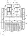
図1,図2は、本発明にかかる部品実装装置の概略構成を示しており、図1は、平面図で、図2は、正面図でそれぞれ部品実装装置を示している。なお、これらの図面には、各図の方向関係を明確にするためにXYZ直角座標軸が示されている。 1 and 2 show a schematic configuration of a component mounting apparatus according to the present invention. FIG. 1 is a plan view and FIG. 2 is a front view showing the component mounting apparatus. In these drawings, XYZ rectangular coordinate axes are shown in order to clarify the directional relationship between the drawings.
この部品実装装置は、基台1上に基板搬送機構2(本発明の搬送手段に相当する)を備えている。基板搬送機構2は、一対のコンベア2a,2bを有しており、これらコンベア2a,2bによりプリント配線板(PWB;Printed wiring board:以下、基板Pという)
を所定の搬送方向(図1の例では右側から左側)へ搬送する。そして、これらコンベア2a,2bにより構成される搬送経路の途中が実装作業位置(図1に示す基板Pの位置)とされ、コンベア2a,2bは、装置右側から基板Pをこの実装作業位置に搬入し、実装作業終了後は、この実装作業位置から装置左側に基板Pを搬送する。
This component mounting apparatus includes a substrate transfer mechanism 2 (corresponding to the transfer means of the present invention) on a
Is conveyed in a predetermined conveyance direction (in the example of FIG. 1, from the right side to the left side). Then, the middle of the transport path constituted by the
前記搬送経路において、実装作業位置の下方には図外の支持装置が配備されている。この支持装置は、複数の支持ピンを具備した支持部材を昇降可能に備え、当該支持部材により基板Pをコンベア2a,2bから持ち上げた状態で位置決め固定する。
A support device (not shown) is provided below the mounting work position in the transport path. This support device includes a support member having a plurality of support pins so that it can be moved up and down, and the substrate P is positioned and fixed in a state where the substrate P is lifted from the
なお、前記コンベア2a,2bのうち装置前側(図1では下側)に位置するコンベア2aは基台1上に固定されており(適宜、固定コンベア2aという)、装置後側に位置するコンベア2bは、前記固定コンベア2aに対してY軸方向に変位可能に設けられ(適宜、可動コンベア2bという)、モータを駆動源とするねじ送り機構等により駆動されるようになっている。つまり、基板搬送機構2は、基板Pのサイズに応じて両コンベア2a,2bの間隔を、固定コンベア2aを基準として変更可能な構成となっている。
Of the
基板搬送機構2の前後両側には、基板Pに搭載するための電子部品を供給する部品供給部3,4が設けられている。
On both front and rear sides of the
これら部品供給部3,4のうち、基板搬送機構2の前側(図1では下側)に位置する部品供給部3には、集積回路(IC)、トランジスタ、抵抗、コンデンサ等の小片状のチップ電子部品を供給するための複数のテープフィーダ3aが並設されている。各テープフィーダ-3aには、電子部品を収納したテープを巻回したリール(図示省略)が保持されており、各テープフィーダ3aは、当該リールから前記テープを繰り出しつつ固定コンベア2a近傍の部品取り出し位置に対して電子部品を供給する。
Among these
一方、基板搬送機構2の後側に位置する部品供給部4には、SOP(Small Outline Package )やQFP(Quad Flatpack Package )等の大型の電子部品を供給するための一対のトレイフィーダ4aが並設されている。各トレイフィーダ4aは、電子部品を載置したトレイTを保持するための複数段のパレット5aを備えるトレイ収納部5と、このトレイ収納部5内のトレイTを引き出すトレイ引き出し機構6等とを備えており、前記トレイ収納部5を上下に移動させつつ所定高さ位置に所望のトレイTを配置し、当該トレイTを前記トレイ引き出し機構によりパレット5aと共にトレイ収納部5前方に引き出し、可動コンベア2b近傍の所定の部品取り出し位置に(実線で図示するトレイTの位置)配置する。
On the other hand, a pair of
前記基台1の上方には、前記各フィーダ3a,4aによって供給される電子部品を基板P上に搬送して搭載(実装)するためのヘッドユニット7が配備されている。
Above the
このヘッドユニット7には、部品実装用の軸状のヘッド8が複数本搭載されており、当実施形態では、6本のヘッド8がX軸方向に等間隔で一列に配列された状態で搭載されている。各ヘッド8の先端(下端)には部品吸着用のノズル8aが装着されている。これらノズル8aは、各々図略の切替弁を介して負圧発生装置に連通可能とされており、この負圧発生装置から負圧の供給を受けることによりノズル8a先端で電子部品を吸着する。
A plurality of shaft-
各ヘッド8は、Z軸サーボモータ16(図4に示す)を駆動源とする図外のヘッド昇降駆動機構を介してヘッドユニット7に対して昇降(Z軸方向の移動)可能に、かつR軸サーボモータ17を駆動源(図4に示す)とする図略のヘッド回転駆動機構を介してヘッドユニット7に対して中心軸回りに回転(R軸方向に変位)可能に支持されている。
Each
これらの駆動機構のうち、ヘッド昇降駆動機構は、電子部品の吸着もしくは搭載を行う際の下降位置と電子部品の搬送や画像認識を行う時の上昇位置との間でノズル8aを昇降させるものである。一方、ヘッド回転駆動機構は、ノズル8aを必要に応じて回転させることにより、電子部品をR軸方向の所定位置に変位させるものである。なお、当実施形態では、上記モータ12,14,16,17を含むヘッド8の各駆動機構が本発明に係る移動手段に相当する。
Among these drive mechanisms, the head lifting drive mechanism lifts and lowers the
前記ヘッドユニット7には、さらに基板Pを画像認識するための基板認識カメラ9が搭載されている。この基板認識カメラ9は、LED等の照明を備えたCCDカメラやCMOSカメラからなり、実装作業位置に配置された基板Pを撮像するためにヘッドユニット7に対して下向き固定されている。なお、後述するが、この基板認識カメラ9は、後記模擬実装用テーブル20及びその上に搭載される治具部品25の画像認識にも用いられており、従って、当実施形態では、この基板認識カメラ9が本発明の撮像手段に相当する。
The head unit 7 is further equipped with a
ヘッドユニット7は、電子部品を各ノズル8aにより吸着して部品供給部3,4から実装作業位置の基板P上に搬送、搭載するため、基台1上の一定の領域(図1中の一点鎖線に示す領域)内においてX軸方向及びY軸方向に移動可能に設けられている。すなわち、ヘッドユニット7は、X軸方向に延びるヘッド支持部材10に対してX軸方向に沿って移動可能に支持されており、このヘッド支持部材10は、基台1上に固定されたY軸方向に延びる固定レール11に移動可能に支持されている。そして、ヘッドユニット7がX軸サーボモータ14によりボールねじ15を介してX軸方向に駆動される一方、ヘッド支持部材10がY軸サーボモータ12によりボールねじ13を介してY軸方向へ駆動されるようになっている。
The head unit 7 picks up electronic components by the
なお、前記基台1上には、各ノズル8aによる電子部品の吸着状態を画像認識するための部品認識カメラ18が配設されている。この部品認識カメラ18は、LED等の照明を備えたCCDカメラやCMOSカメラからなり、部品供給部4の各トレイフィーダ4aの間、詳しくは部品取り出し位置の間に配置され、各ノズル8aによる吸着部品を撮像するために基台1上に上向きに固定されている。
A
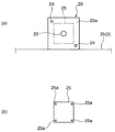
また、この部品認識カメラ18の近傍位置には、部品の模擬搭載用テーブル20が設けられている。この模擬搭載用テーブル20(以下、テーブル20と略す)は、後述するキャリブレーション処理(本発明に係る搭載誤差取得動作に相当する)において後記治具部品25を搭載するためのもので、可動コンベア2bの後側面(図1では上側の側面)に固定され、この可動コンベア2bと一体的に変位可能に設けられている。このテーブル20は、図3(a)に示すように部品を搭載するための平面視略正方形でかつ平坦な部品の搭載面20aを有しており、この搭載面20aの高さ位置は、実装作業位置に固定される基板Pの部品搭載面と同じ高さ位置に設定されている。前記搭載面20aには、その対角線上であって相対向する一対の角部にテーブル20の位置を画像認識するためのフィデューシャルマーク24がそれぞれ記されており、さらに搭載面20a上であって両フィデューシャルマーク24を結ぶ線分の中心位置には吸引孔22が設けられている。この吸引孔22は、図外の配管および切替弁を介して負圧発生装置に連通可能とされており、テーブル20は、この負圧発生装置から吸引孔22に負圧の供給を受けることにより電子部品を搭載面20a上に吸着、保持する。なお、当実施形態では、この吸引孔22、切替弁及び負圧発生装置等が本発明の吸着手段に相当する。
Further, a component mounting table 20 is provided in the vicinity of the
テーブル20上には、治具部品25が載置されており、キャリブレーション処理では、この治具部品25が前記ノズル8aにより吸着、保持され、その吸着状態が部品認識カメラ18を用いて画像認識された後、搭載面20aに搭載される。この治具部品25は、図3(b)に示すように、平面視正方形でかつ厚み方向に扁平な形状を有しており、全体がガラス等で構成されている。治具部品25の上面には、その四隅であってそれぞれ対角線上の位置に部品認識用のマーク25aが記されている。
A
図4は、この部品実装装置の制御系を機能ブロックで概略的に示している。 FIG. 4 schematically shows a control system of this component mounting apparatus in functional blocks.
この同図に示すように、部品実装装置は、その動作を統括的に制御するための制御装置30を備えている。この制御装置30は、その機能構成として演算処理部301、プログラム記憶部302、データ記憶部303、モータ制御部304、外部入出力部305及び画像処理部306等を含む。
As shown in the figure, the component mounting apparatus includes a
演算処理部301は、論理演算を実行する周知のCPU、各種プログラムを記憶するROM、装置動作中の様々なデータを一時的に記憶するRAM等からなり、プログラム記憶部302内の所定の実装プログラムおよびデータ記憶部303内の各種データに基づきモータ制御部304を介して各サーボモータ12,14,16,17等を駆動制御することにより部品の実装動作を実行すると共に後述するキャリブレーション処理を実行するものである。また、演算処理部301は、この実装動作やキャリブレーション処理において必要となる各種演算処理を行う。
The
プログラム記憶部302は、基板Pに電子部品を実装するための生産プログラム(実装プログラム)や、キャリブレーション処理を実行するためのキャリブレーションプログラム等を記憶するものである。
The
データ記憶部303は、基板Pへの電子部品の実装やキャリブレーション処理に必要な各種データを記憶するものである。例えば基板P上における電子部品の実装座標データ等を含む基板データや、電子部品の形状や大きさ等のデータを含む部品データ等がこのデータ記憶部303に記憶されている。また、キャリブレーション処理の結果として演算処理部301でより求められる後記搭載誤差データもこのデータ記憶部303に記憶される。
The
モータ制御部304は、ヘッドユニット7の各サーボモータ12,14,16,17等の駆動を制御するものである。
The
外部入出力部305は、この部品実装装置が備える各種センサ類、弁(バルブ)等の駆動部に対する信号の入出力を制御するものである。
The external input /
画像処理部306は、基板認識カメラ9および部品認識カメラ18から出力される画像データに所定の画像処理を施すことにより必要な情報を抽出可能にするものである。
The
この制御装置30(演算処理部301)には、各種データの入力や各種動作の実行指示を与えるためのキーボード及びマウス等の入力ユニット32と、実装動作やキャリブレーション処理の動作状況やこれらの動作に伴う各種情報を表示する液晶ディスプレイ等の表示ユニット34とが接続されており、表示ユニット34に表示される内容に基づき、オペレータが必要に応じて入力ユニット32を操作して各種情報の入力を行う。
The control device 30 (arithmetic processing unit 301) includes an
なお、当実施形態では、演算処理部301が本発明の演算手段及び補正手段として機能し、演算処理部301およびモータ制御部304が本発明の制御手段として機能し、入力ユニット32が本発明の指示手段に相当する。
In this embodiment, the
次に、この制御装置30(演算処理部301)による部品の実装動作制御の一例について図5のフローチャートに基づいて説明する。 Next, an example of component mounting operation control by the control device 30 (arithmetic processing unit 301) will be described based on the flowchart of FIG.
実装動作が開始されると、演算処理部301は、まず基板Pを実装作業位置に搬入して位置決め固定し(ステップS1)、さらに、ヘッドユニット7を基板P上に移動させて基板認識カメラ9により基板P上のフィデューシャルマークを撮像し、この画像データに基づき基板Pの位置を認識する(ステップS3)。
When the mounting operation is started, the
次いで演算処理部301は、ヘッドユニット7を部品供給部3,4に移動させて各ヘッド8(ノズル8a)により電子部品を吸着する(ステップS5)。詳しくは、テープフィーダ3a又はトレイフィーダ4aの部品取り出し位置の上方にヘッドユニット7を配置した後、ヘッド8を昇降させてテープ内又はトレイT内の電子部品をノズル8aにより吸着する。この際、可能な場合には、複数のヘッド8により同時に複数の部品を吸着する。
Next, the
演算処理部301は、次に、ヘッドユニット7を部品認識カメラ18上に移動させて各ノズル8aの吸着部品を撮像し、その画像データに基づいて各ノズル8aに対する部品の吸着状態(吸着誤差)を調べる(ステップS7)。
Next, the
そして、この部品認識が完了すると、演算処理部301は、ヘッドユニット7を実装作業位置の基板P上に移動させ、ヘッド8を昇降させることにより最初の電子部品を基板P上に搭載し、以後、ヘッドユニット7を間欠的に実装ポイントに移動させながら、各ヘッド8に吸着されている残りの電子部品を順次基板P上に搭載する(ステップS9)。この際、演算処理部301は、ステップS7での吸着部品の認識結果とデータ記憶部303に記憶されている搭載誤差データ(ΔX,ΔY,ΔR)、つまりヘッドユニット7及びヘッド8等の駆動誤差によって発生する搭載誤差であって後述するキャリブレーション処理によって求められたデータとに基づき、ヘッド8による部品の搭載座標データを補正し、この補正後の搭載座標データに従ってヘッドユニット7等を駆動制御する。
When the component recognition is completed, the
各ヘッド8による部品の搭載が終了すると、演算処理部301は、当該基板Pに対して全ての部品を搭載したか否かを判断し(ステップS11)、ここでNOと判断した場合には、ステップS5に移行して次の電子部品の吸着動作を行う。これに対してステップS11でYESと判断すると、演算処理部301は、基板搬送機構2および支持装置を駆動制御することにより基板Pの固定を解除して実装作業位置から当該基板Pを搬出する(ステップS13)。これにより一連の実装動作を終了する。
When the mounting of the components by each
なお、このような実装動作が繰り返されると、摩耗等の経時劣化によりヘッドユニット7やヘッド8(ノズル8a)に駆動誤差が生じる場合がある。この部品実装装置では、このような駆動誤差を検知し、その結果を電子部品の搭載座標補正用のデータとして更新的に記憶するキャリブレーション処理が実行可能となっている。以下、前記制御装置30(演算処理部301)による当該キャリブレーション処理の動作制御について図6及び図7のフローチャートに基づき詳しく説明する。
If such a mounting operation is repeated, a drive error may occur in the head unit 7 or the head 8 (
このキャリブレーション処理は、オペレータが入力ユニット32を操作して制御装置30(演算処理部301)に実行指示を与えることにより開始される。
This calibration process is started when the operator operates the
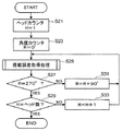
キャリブレーション処理が開始されると、図6に示すように、演算処理部301は、まずヘッドカウンタHに初期値「1」を、角度カウンタRに初期値「0°」を順次セットした後、搭載誤差取得処理に移行する(ステップS21〜S25)。
When the calibration process is started, as shown in FIG. 6, the
図7は、ステップ25の搭載誤差取得処理を示すフローチャート(サブルーチン)である。この処理が開始されると、演算処理部301は、搭載回数カウンタNをリセットし、ヘッドユニット7を制御することにより、模擬実装用の前記テーブル20上に載置されている治具部品25をノズル8aにより吸着する(ステップS41,S43)。この際、演算処理部301は、前記カウンタ値に基づく吸着条件、つまり、図6のステップS21の処理でセットされたヘッドカウンタHの値により特定されるヘッド8を用い、かつ当該ヘッド8を同ステップS23でセットされた角度カウンタRの値により特定されるR軸方向の位置(回転角度)にセットした状態で治具部品25を吸着する。例えば初期値「H=1」「R=0°」の場合には、演算処理部301は、第1番目(例えば図2中の最も左端のヘッド8)の回転角度を基準角度(=0°)にセットした状態で当該ヘッド8により治具部品25の吸着を行う。
FIG. 7 is a flowchart (subroutine) showing the mounting error acquisition processing in
治具部品25の吸着が完了すると、演算処理部301は、ヘッドユニット7を部品認識カメラ18上に移動して治具部品25を撮像し、その画像データに基づいてノズル8aによる治具部品25の吸着状態(吸着誤差)を調べ、その結果を保存する(ステップS45)。
When the suction of the
次に、演算処理部301は、搭載回数カウンタNの値が「0」か否かを判断し(ステップS47)、ここでYESと判断した場合には、ヘッドユニット7を移動させ、テーブル20の上方に基板認識カメラ9を配置してフィデューシャルマーク24を撮像し、その画像データに基づきテーブル20の位置を認識すると共にその結果をデータ記憶部303に更新的に記憶する(ステップS49)。なお、ステップS47でYESと判断した場合には、ステップS49の処理はスキップする。
Next, the
テーブル20の認識が終わると、演算処理部301は、ヘッドユニット7を制御することにより前記搭載面20a上に治具部品25を搭載する(ステップS51)。この際、演算処理部301は、ステップS49で記憶したテーブル20の位置データとステップS45での治具部品25の認識結果とに基づき、予め設定された目標座標(X,Y,R)に治具部品25が搭載されるようにヘッドユニット7を駆動制御する。
When the recognition of the table 20 is completed, the
演算処理部301は、次に、ヘッドユニット7を移動させてテーブル20の上方に基板認識カメラ9を配置し、治具部品25の前記マーク25aを撮像することによりその画像データに基づいて治具部品25の位置を認識する(ステップS53)。そして、前記目標位置(X,Y,R)に対する搭載誤差を演算し、これを搭載誤差データ(δx,δy,δr)として仮保存する(ステップS55,S57)。つまり、ステップS45,S49の結果を加味して治具部品25をテーブル20上に搭載した場合、ヘッドユニット7やヘッド8に駆動誤差が無ければ治具部品25は目標座標(X,Y,R)に搭載されるが、ヘッドユニット7やヘッド8に駆動誤差があるとそれに等しい搭載誤差が生じることとなる。
Next, the
演算処理部301は、次に、搭載回数カウンタNをインクリメントし(ステップS59)、搭載回数カウンタNの値が予め設定された回数に達したか否かを判断する(ステップS61)。ここで、NOと判断した場合には、演算処理部301は、ステップS43にリターンする。つまり、同じ吸着条件(図5のステップS21,S23のカウンタ値に基づく吸着条件)で設定回数分だけテーブル20上への治具部品25の搭載を繰り返すことにより当該設定回数分の搭載誤差データ(δx,δy,δr)を取得する。
Next, the
ステップS61でNOと判断した場合には、演算処理部301は、ステップS57で仮保存した上記設定回数分の搭載誤差データ(δx,δt,δr)を読み出し、この搭載誤差データの各要素のそれぞれ平均値(ΔX,ΔY,ΔR)を演算すると共にこの値が予め設定されている精度規格値外か否かを判断し、その結果を前記平均値(ΔX,ΔY,ΔR)と共に表示ユニット34に表示する(ステップS63)。ここで、NOと判断した場合には、搭載誤差取得処理を終了する。
If NO is determined in step S61, the
これに対してステップS63でYESと判断した場合には、演算処理部301は、さらに補正実施設定がされているか否かを判断する(ステップS65)。つまり、キャリブレーション結果を実装動作に反映させるか否かを判断し、ここでYESと判断した場合には、ステップS63での演算結果を、上記吸着条件における最終的な搭載誤差データ(ΔX,ΔY,ΔR)としてデータ記憶部303に更新的に格納した後(ステップS67)、搭載誤差取得処理を終了する。例えばデータ記憶部303には、図8に示すようなテーブルデータ、すなわち各ヘッド8とR軸の回転角度(0°,90°,180°,270°)と搭載誤差との関係を示すテーブルデータ(初期値は全て0)が予め記憶されており、ステップS67の処理では、上記吸着条件に対応するフィールドに上記搭載誤差データ(ΔX,ΔY,ΔR)を上書き保存する。
On the other hand, when it is determined YES in step S63, the
なお、ステップS65の補正実施設定は、例えばオペレータが入力ユニット32の操作に基づきキャリブレーション処理の実行指示を制御装置30に与える際に併せて行う。
The correction execution setting in step S65 is also performed when the operator gives an instruction to execute calibration processing to the
搭載誤差取得処理が終了すると、図6のステップS27に移行し、演算処理部301は、角度カウンタRが「270°」が否かを判断し(ステップS27)、ここで、NOと判断した場合には、角度カウンタRをインクリメント(R=R+90°)した後、ステップS25にリターンする。これに対して、ステップS27でYESと判断した場合には、演算処理部301は、さらにヘッドカウンタHがヘッド数か、つまり、当実施形態では「6」か否かを判断し(ステップS29)、ここで、NOと判断した場合には、ヘッドカウンタHをインクリメント(H=H+1)した後、ステップS25にリターンする。このようにステップS25〜S33の処理を繰り返すことにより、図8のテーブルデータの全てのフィールドに搭載誤差データ(ΔX,ΔY,ΔR)を上書き保存する。
When the mounting error acquisition process is completed, the process proceeds to step S27 in FIG. 6, and the
そして、最終的にステップS29でYESと判断すると、演算処理部301は、キャリブレーション処理を終了する。
Then, when it is finally determined YES in step S29, the
このようにキャリブレーション処理が実行されると、演算処理部301は、その後の実装動作制御(図5のステップS9の処理)において上記テーブルデータ(図8参照)を参酌し、搭載誤差データと電子部品の吸着誤差データとに基づいて電子部品の搭載座標データを補正する。具体的には、ヘッド8(ノズル8a)毎に対応する搭載誤差データ(ΔX,ΔY,ΔR)を上記テーブルデータから読み出し、この搭載誤差データと図5のステップS7の処理で求められた吸着誤差データとに基づき電子部品の搭載座標データ(x,y,r)を補正し、この補正後の搭載座標データに基づいてヘッドユニット7を駆動制御する。これにより、ヘッドユニット7やヘッド8等の駆動誤差がその後の実装動作制御に反映されることとなる。
When the calibration processing is executed in this way, the
なお、上記の説明では言及していなかったが、演算処理部301は、切替弁を制御することによりテーブル20(吸引孔22)に対して負圧の供給をオンオフする。具体的には、ヘッド8による治具部品25の吸着時点から搭載面20a上に搭載される時点(ステップS43〜S51)までの間は負圧供給をオフし、それ以外は負圧供給をオンする。つまり、このように負圧供給オンオフすることで、テーブル20上に治具部品25を負圧吸着して治具部品25の意図しない位置ずれやテーブル20からの脱落を未然に防止する一方で、必要に応じてヘッド8による治具部品25の吸着を難なく行い得るようになっている。
Although not mentioned in the above description, the
また、キャリブレーション処理は、上記の通り、オペレータが入力ユニット32の操作に基づき演算処理部301に実行指示を与えることにより開始されるが、基板Pに対する電子部品の実装作業中に当該操作(実行指示の入力)がされた場合には、演算処理部301は、実装作業を中断した上、キャリブレーション処理を優先的に実行する。
Further, as described above, the calibration process is started when the operator gives an execution instruction to the
例えば、演算処理部301は、電子部品の搭載(実装)動作中に実行指示があった場合には、前記ヘッド8による吸着部品の搭載が完了した段階まで実装プログラムを進め、その後、キャリブレーション処理プログラムを実行する。これにより実装作業中の基板Pを実装作業位置に待機させたままキャリブレーション処理を実行する。この際、各ヘッド8によりテーブル20に対して治具部品25の吸着及び搭載を行うが、上記の通り、テーブル20はコンベア2a,2bの外側、つまり実装作業位置がある搬送経路の外側に設けられているため、実装作業中の基板Pを実装作業位置に待機させた状態で難なくキャリブレーション処理を実行することができる。そして、キャリブレーション処理後、演算処理部301は、更新された上記テーブルデータに基づき残りの電子部品の搭載座標データを補正した上で、中断した実装プログラムを再開する。これによりキャリブレーション処理の結果が速やかに実装作業中の基板Pの生産に反映されることとなる。
For example, if there is an execution instruction during the mounting (mounting) operation of the electronic component, the
このように上記実施形態の部品実装装置では、模擬実装用のテーブル20上に治具部品25を搭載し、当該治具部品25を画像認識するキャリブレーション処理を実行することにより搭載誤差データ(ΔX,ΔY,ΔR)を取得し、必要に応じてこの搭載誤差データをその後の実装作業に反映させ得る構成となっているため、経時劣化等に伴い生じるヘッドユニット7やヘッド8等の駆動誤差を実装作業に反映させつつ実装精度の高い部品実装基板を長期的に安定して生産することが可能となる。
As described above, in the component mounting apparatus of the above-described embodiment, the mounting error data (ΔX is obtained by mounting the
しかも、この装置では、上記の通り模擬実装用のテーブル20を実装作業位置よりも外側、具体的にはコンベア2a,2bの外側に配置しておき、キャリブレーション処理では、このテーブル20上に治具部品25を搭載してこれを画像認識する構成であり、実装作業位置に基板Pを配置した状態でもキャリブレーション処理を実施することができる。そのため、オンライン状態であっても一時的に実装作業を中断すれば難なくキャリブレーション処理を実行することができる。従って、抜き取り検査等で部品の搭載不良が見つかった場合等には、直ちにキャリブレーション処理を実行して不良原因の検証等を行うことで、その結果をその後の生産に速やかに反映させることができるという利点がある。特に、実施形態の装置は、基板Pの実装作業中にキャリブレーション処理の実行指示があると、当該基板Pの実装作業を中断してキャリブレーション処理を実行し、その結果を再開された当該基板Pの実装作業に直ちに反映させる構成となっているので、キャリブレーション処理の結果を可及的速やかに実装作業に反映させることができるという利点がある。
In addition, in this apparatus, the simulation mounting table 20 is arranged outside the mounting work position, specifically, outside the
また、実施形態の装置では、テーブル20の搭載面20aと実装作業位置に固定される基板Pの部品搭載面とが同じ高さに設定されており、さらに治具部品25を用いてキャリブレーション処理を行うので、求められる搭載誤差データ(ΔX,ΔY,ΔR)の信頼性が高いという利点もある。すなわち、テーブル20の搭載面20aと基板Pの部品搭載面とが同じ高さであることにより、ヘッド8の昇降に伴う軸ぶれ等により生じる搭載誤差をキャリブレーション処理において正確に再現させることできる。また、治具部品25を用いることで部品の形状や大きさが統一されて部品の認識にバラツキが生じ難くなり、これらの結果、搭載誤差データ(ΔX,ΔY,ΔR)の信頼性を高めることができる。但し、本発明はキャリブレーション処理において製品部品を用いることを否定するものではなく、例えば治具部品25の代わりにQFP等の部品をトレイフィーダ4aから吸着し、これをテーブル20上に搭載するようにしても構わない。この場合、予めキャリブレーション処理に用いる製品部品の種類を特定しておくことで、治具部品25を用いる場合と同様に部品認識精度の安定化を図ることが可能となる。
Further, in the apparatus of the embodiment, the mounting
また、実施形態の装置では、テーブル20が基板搬送機構2に固定されている。このように基板Pの部品搭載面に近い位置にテーブル20が設置されているため、搭載誤差をより高精度に取得することができる。また、実施形態の装置のように、基板搬送機構2である可動コンベア2bにテーブル20を固定し、この可動コンベア2bと一体的にテーブル20を変位可能に設けた場合に、テーブル20が基板Pのサイズ変更に伴う可動コンベア2bの移動の邪魔になることがないという利点もある。
In the apparatus according to the embodiment, the table 20 is fixed to the
なお、上記実施形態の部品実装装置では、実装プログラムとは別にキャリブレーション処理プログラムを備えておき、キャリブレーション処理を実装作業から切り離して実施することにより、全部品の実装動作に用いる共通の搭載誤差データ(ΔX,ΔY,ΔR)を求める構成となっているが、例えばキャリブレーション処理プログラムに相当するプログラムを実装プログラムに予め組み込んでおくことにより、部品毎に実質的なキャリブレーション処理を実行しながら実装作業を進めるように構成してもよい。 In the component mounting apparatus of the above embodiment, a calibration processing program is provided separately from the mounting program, and the calibration processing is performed separately from the mounting operation, so that a common mounting error used for the mounting operation of all components can be performed. The data (ΔX, ΔY, ΔR) is obtained. For example, a program corresponding to the calibration processing program is incorporated in the mounting program in advance so that the substantial calibration processing is executed for each component. You may comprise so that mounting operation may be advanced.
以下、その場合の部品実装装置の構成および動作制御の一例について説明する。 Hereinafter, an example of the configuration and operation control of the component mounting apparatus in that case will be described.
この場合の部品実装装置の構成も基本的には実施形態のものと共通するが、上記の通りプログラム記憶部302には専用のキャリブレーション処理プログラムは記憶されておらず、また、テーブル20上に治具部品25は置かれていない。この点で構成が相違する。
The configuration of the component mounting apparatus in this case is also basically the same as that of the embodiment, but as described above, the dedicated calibration processing program is not stored in the
図9は、制御装置30(演算処理部301)による実装動作制御の一例を示すフローチャートである。 FIG. 9 is a flowchart illustrating an example of mounting operation control by the control device 30 (arithmetic processing unit 301).
実装動作が開始されると、演算処理部301は、まず基板Pを実装作業位置に搬入して位置決め固定し、さらに基板Pが固定されると、ヘッドユニット7を基板P上に移動させて基板認識カメラ9により基板P上のフィデューシャルマークを撮像し、この画像データに基づき基板Pの位置を認識する(ステップS71)。
When the mounting operation is started, the
次いで演算処理部301は、ヘッドユニット7を部品供給部3,4に移動させて各ヘッド8(ノズル8a)により電子部品を吸着し(ステップS73)、部品吸着が完了すると、さらにヘッドユニット7を部品認識カメラ18上に移動させて各ノズル8aの吸着部品を撮像し、その画像データに基づいて各ノズル8aに対する部品の吸着状態(吸着誤差)を調べる(ステップS75)。
Next, the
部品認識が終了すると、演算処理部301は、ヘッドユニット7を移動させて前記テーブル20上のフィデューシャルマーク24を基板認識カメラ9により撮像し、その画像データに基づきテーブル20の位置を認識した後、テーブル20上に吸着部品を搭載する(ステップS77,S79)。この際、演算処理部301は、ステップS75,77の認識結果に基づき搭載面20a上の予め設定された目標位置(X,Y,R)に電子部品が搭載されるようにヘッドユニット7等を駆動制御する。
When the component recognition is completed, the
演算処理部301は、次に、ヘッドユニット7を移動させてテーブル20の上方に基板認識カメラ9を配置することにより電子部品の所定の認識箇所を撮像し、その画像データに基づいて電子部品の位置を認識すると共に前記目標位置(X,Y,R)に対する搭載誤差を演算(δx,δy,δr)し、その後、元のヘッド8により当該電子部品を吸着させる(ステップS81〜S89)。なお、リード付きのパッケージ部品であれば、例えば特定のリード(又は全リード)の先端部分が認識箇所とされ、又リード無しパッケージ部品であればその角部が認識箇所とされ、ステップS83の処理では、当該認識箇所を撮像しその画像データに基づき電子部品の位置を認識する。
Next, the
そして、電子部品を吸着している全ヘッド8について搭載誤差を求めたか否かを判断し(ステップS91)、ここでNOと判断した場合には、ステップS79に移行し、残りのヘッド8について同様の処理を実行する。これに対して、ステップS91でYESと判断した場合には、演算処理部301は、ヘッドユニット7を部品認識カメラ18上に移動させて各ノズル8aの吸着部品を撮像し、その画像データに基づいて各ノズル8aに対する部品の吸着状態(吸着誤差)を求める(ステップS93)。
Then, it is determined whether or not mounting errors have been obtained for all the
次いで、演算処理部301は、ヘッドユニット7を実装作業位置の基板P上に移動させ、ヘッド8を昇降させることにより最初の電子部品を基板P上に搭載し、以後、ヘッドユニット7を間欠的に実装ポイントに移動させながら、各ヘッド8に吸着されている残りの電子部品を順次基板P上に搭載する(ステップS95)。
Next, the
各ヘッド8による部品の搭載が終了すると、演算処理部301は、当該基板Pに対して全ての部品を搭載したか否かを判断し(ステップS97)、ここでNOと判断するとステップS73に移行して次の電子部品の吸着動作を行う。これに対してステップS97でYESと判断すると、演算処理部301は、基板搬送機構2および支持装置を駆動制御することにより基板Pの固定を解除して実装作業位置から当該基板Pを搬出し(ステップS99)、一連の実装動作を終了する。
When the mounting of the components by each
このような部品実装装置によると、実質的なキャリブレーション処理(ステップS77〜S87の処理)が部品毎に実行されながら実装作業が進められることとなる。そのため、ヘッドユニット7等の駆動誤差をリアルタイムで実装作業に反映させることが可能となり、その結果、より精度良く部品実装基板を生産することが可能となる。 According to such a component mounting apparatus, a mounting operation is performed while a substantial calibration process (the processes in steps S77 to S87) is performed for each component. Therefore, it is possible to reflect the drive error of the head unit 7 and the like in the mounting operation in real time, and as a result, it is possible to produce a component mounting board with higher accuracy.
なお、ここでは、図9の例に示すように部品単位でキャリブレーション処理を実行しながら実装作業を進める例について説明したが、これ以外にも、例えば、所定数(複数)の部品単位でキャリブレーション処理を実行しながら実装作業を進めるようにしてもよい。この場合には、ステップS87の処理で求めた各ヘッド8の搭載誤差データをデータ記憶部303に記憶し、当該搭載誤差データに基づき所定数(複数)の電子部品の実装作業を行った後に(つまり、ステップS77〜スS93の処理をスキップする)、ステップS77〜スS93のキャリブレーション処理を実行してデータ記憶部303内の搭載誤差データを更新するようにすればよい。
Here, as shown in the example of FIG. 9, the example in which the mounting operation is performed while executing the calibration process in units of components has been described. However, in addition to this, for example, calibration is performed in units of a predetermined number (a plurality) of components. The mounting operation may be advanced while executing the processing. In this case, the mounting error data of each
ところで、以上説明した部品実装装置は、本発明に係る部品実装装置の好ましい実施形態の一例であって、その具体的な構成は本発明の要旨を逸脱しない範囲で適宜可能である。 By the way, the component mounting apparatus described above is an example of a preferred embodiment of the component mounting apparatus according to the present invention, and a specific configuration thereof can be appropriately made without departing from the gist of the present invention.
例えば、図5〜図7に示す動作制御では、オペレータによる入力ユニット32の操作に基づきキャリブレーション処理を実行するようにしているが、例えば生産品種の変更時、設定時間の経過時、電源投入時等、予め設定したタイミングで自動的にキャリブレーション処理が実行されるようにしてもよい。この場合には、キャリブレーション処理後の搭載誤差データ(テーブルデータ)に従って自動的にその後の実装動作が制御されるようにすればよい。
For example, in the operation control shown in FIGS. 5 to 7, the calibration process is executed based on the operation of the
また、実施形態では、基板Pの部品搭載面とテーブル20の搭載面20aとの高さを等しく設けるためにテーブル20を両固定コンベア2aの外側、具体的には可動コンベア2bの後側面に固定しているが、基板Pとの干渉を回避し得る範囲であってかつ基板Pの部品搭載面の外側である両固定コンベア2aの内側に配置するようにしてもよい。つまり、基板Pの部品搭載面とテーブル20の搭載面20aとの高さを等しく設けているのは、ヘッド8の昇降に伴う軸ぶれ等により生じる搭載誤差をキャリブレーション処理において正確に再現して搭載誤差データの信頼性を高めるためである。従って、当該信頼性を著しく損なわない範囲であれば、基板Pの部品搭載面に対してテーブル20の搭載面20aを多少低く設けることも可能であり、この場合には、テーブル20を両コンベア2a,2bの間に配置するようにしてもよい。
In the embodiment, the table 20 is fixed to the outside of the fixed
また、実施形態では、テーブル20の搭載面20aに吸引孔22を形成し、この吸引孔22を通じて治具部品25を吸引することによりテーブル20上に治具部品25を吸着、保持する構成となっているが、吸引孔22の代わりに粘着性を有するシート部材等を搭載面20aに設けることにより、当該シート部材の粘着力で治具部品25をテーブル20上に吸着、保持する構成としてもよい。
In the embodiment, the
2 基板搬送機構
2a,2b コンベア
3,4 部品供給部
3a テープフィーダ
4a トレイフィーダ
7 ヘッドユニット
8 ヘッド
8a ノズル
20 模擬実装用テーブル
25 治具部品
30 制御装置
301 演算処理部
302 プログラム記憶部
303 データ記憶部
304 モータ制御部
305 外部入出力部
306 画像処理部
P 基板
2
Claims (4)
前記実装作業位置に配置される被実装基板に対して水平方向及び上下方向に前記ヘッドを相対的に移動させるための移動手段と、
前記搬送経路の外側に配置され、かつ、前記被実装基板の部品搭載面と同じ高さに位置する部品搭載が可能な搭載面を備える模擬実装用テーブルと、
この模擬実装用テーブル上に搭載された部品を撮像する撮像手段と、
この撮像手段により取得した画像に基づき所定の目標位置に対する部品の搭載誤差を求める演算手段と、
前記搭載誤差に基づき前記ヘッドによる部品の搭載座標を補正する補正手段と、
前記模擬実装用テーブル上に部品を搭載して当該部品を前記撮像手段によって撮像することにより前記搭載誤差を求める所定の搭載誤差取得動作を実行すべく前記移動手段を制御する制御手段と、を備え、
この制御手段は、前記被実装基板上に部品を搭載する所定の部品実装動作を実行すべく前記移動手段を制御するとともに、この部品実装動作中に、前記ヘッドにより前記部品供給部から取り出される部品を用いて前記搭載誤差取得動作を実行し、この搭載誤差取得動作により取得した搭載誤差に基づき前記補正手段によって補正される搭載座標に従って前記被実装基板上に部品を搭載すべく前記移動手段を制御することを特徴とする部品実装装置。 A transport unit that transports the substrate to be mounted in a specific direction, a component supply unit that supplies components to be mounted on the substrate to be mounted , and a position in the middle of the substrate transport path by the transport unit as a mounting work position , In a component mounting apparatus comprising a component mounting head that is mounted on a mounted substrate that is taken out of a component supply unit and placed on the mounting work position,
Moving means for relatively moving the head in the horizontal direction and the vertical direction with respect to the mounting substrate disposed at the mounting work position;
A simulation mounting table provided with a mounting surface that is disposed outside the transport path and can be mounted with a component that is positioned at the same height as the component mounting surface of the mounted substrate;
Imaging means for imaging components mounted on the simulation mounting table;
Calculation means for obtaining a mounting error of a component with respect to a predetermined target position based on an image acquired by the imaging means;
Correction means for correcting the mounting coordinates of the component by the head based on the mounting error;
Control means for controlling the moving means to perform a predetermined mounting error acquisition operation for mounting the part on the simulated mounting table and imaging the part by the imaging means to obtain the mounting error. ,
The control unit controls the moving unit to execute a predetermined component mounting operation for mounting a component on the mounted substrate, and a component taken out from the component supply unit by the head during the component mounting operation. The mounting error acquiring operation is executed using the mounting error, and the moving means is controlled to mount the component on the mounted substrate according to the mounting coordinates corrected by the correcting means based on the mounting error acquired by the mounting error acquiring operation. component mounting apparatus according to claim to Rukoto.
前記演算手段により求められる搭載誤差を更新的に記憶する記憶手段をさらに備え、
前記補正手段は、この記憶手段に記憶されている搭載誤差に基づき前記ヘッドによる部品の搭載座標を補正し、
前記制御手段は、前記被実装基板に搭載される部品であって予め定められた所定数かつ複数の部品ごとに当該部品を用いて前記搭載誤差取得動作を実行することを特徴とする部品実装装置。 The component mounting apparatus according to claim 1 ,
Further comprising a storage means for updating storage of mounting error is determined by pre-Symbol calculating means,
Wherein the correction means corrects the mounting coordinate of the component by the head based on the mounting error stored in the storage means,
Before SL control means is characterized execution to Rukoto the mounting error acquisition operation by using the components above every predetermined number and a plurality of parts previously determined a component mounted on the mounting substrate Component mounting equipment.
前記模擬実装用テーブル上に置かれた部品を当該テーブル上に吸着した状態で保持する吸着保持手段を備えていることを特徴とする部品実装装置。 In the component mounting apparatus according to claim 1 or 2,
Component mounting apparatus characterized that you have provided a suction holding means for holding the components placed on the simulated mounting table in a state adsorbed on the table.
前記ヘッドにより前記部品供給部から取り出した部品を、前記搬送経路の外側に配置されかつ前記被実装基板の部品搭載面と同じ高さに位置する部品搭載が可能な搭載面を備える模擬実装用テーブル上に搭載する模擬実装工程と、
この工程で前記模擬実装用テーブル上に搭載された部品を撮像手段により撮像、認識することにより所定の目標位置に対する部品の搭載誤差を求める誤差演算工程と、
この工程で求めた搭載誤差に基づき前記ヘッドによる部品の搭載座標を補正した上で被実装基板上に部品を実装する基板生産工程と、を含むことを特徴とする部品実装方法。
From a component supply unit that places a substrate to be mounted, which is transported in a specific direction by a transport unit, at a mounting operation position determined in the course of a substrate transport path by the transport unit, and supplies components to be mounted on the substrate to be mounted In a component mounting method of taking out a component with a component mounting head and mounting the component on the mounted substrate,
A simulated mounting table including a mounting surface on which a component taken out from the component supply unit by the head can be mounted on the outside of the transport path and positioned at the same height as the component mounting surface of the mounted substrate A mock mounting process mounted on top,
In this step, an error calculation step for obtaining a component mounting error with respect to a predetermined target position by imaging and recognizing the component mounted on the simulated mounting table by an imaging unit;
A component mounting method comprising: a substrate production step of mounting a component on a substrate to be mounted after correcting the mounting coordinates of the component by the head based on the mounting error obtained in this step .
Priority Applications (1)
| Application Number | Priority Date | Filing Date | Title |
|---|---|---|---|
| JP2008309442A JP4824739B2 (en) | 2008-12-04 | 2008-12-04 | Component mounting apparatus and component mounting method |
Applications Claiming Priority (1)
| Application Number | Priority Date | Filing Date | Title |
|---|---|---|---|
| JP2008309442A JP4824739B2 (en) | 2008-12-04 | 2008-12-04 | Component mounting apparatus and component mounting method |
Publications (3)
| Publication Number | Publication Date |
|---|---|
| JP2010135534A JP2010135534A (en) | 2010-06-17 |
| JP2010135534A5 JP2010135534A5 (en) | 2011-06-30 |
| JP4824739B2 true JP4824739B2 (en) | 2011-11-30 |
Family
ID=42346535
Family Applications (1)
| Application Number | Title | Priority Date | Filing Date |
|---|---|---|---|
| JP2008309442A Active JP4824739B2 (en) | 2008-12-04 | 2008-12-04 | Component mounting apparatus and component mounting method |
Country Status (1)
| Country | Link |
|---|---|
| JP (1) | JP4824739B2 (en) |
Cited By (1)
| Publication number | Priority date | Publication date | Assignee | Title |
|---|---|---|---|---|
| KR101472434B1 (en) * | 2012-09-07 | 2014-12-12 | 야마하하쓰도키 가부시키가이샤 | Electronic component mounting apparatus and mounting position correction data creating method |
Families Citing this family (4)
| Publication number | Priority date | Publication date | Assignee | Title |
|---|---|---|---|---|
| US9693039B2 (en) | 2010-05-27 | 2017-06-27 | Nintendo Co., Ltd. | Hand-held electronic device |
| JP6264760B2 (en) * | 2012-07-06 | 2018-01-24 | Tdk株式会社 | Mounting method and mounting apparatus |
| JP6745170B2 (en) * | 2016-08-29 | 2020-08-26 | Juki株式会社 | Mounting device, calibration method, and calibration program |
| JP6913851B2 (en) * | 2017-08-24 | 2021-08-04 | パナソニックIpマネジメント株式会社 | Mounting board manufacturing system and mounting board manufacturing method |
Family Cites Families (5)
| Publication number | Priority date | Publication date | Assignee | Title |
|---|---|---|---|---|
| JP3927664B2 (en) * | 1997-10-20 | 2007-06-13 | 松下電器産業株式会社 | Component mounting apparatus and method |
| JPH11168297A (en) * | 1997-12-04 | 1999-06-22 | Matsushita Electric Ind Co Ltd | Judging method and correcting method of working position of work machine, and work machine using thereof |
| JP2003101296A (en) * | 2001-09-20 | 2003-04-04 | Yamagata Casio Co Ltd | Component mounter |
| JP3545387B2 (en) * | 2002-02-04 | 2004-07-21 | 松下電器産業株式会社 | IC component mounting method and device |
| JP4494922B2 (en) * | 2004-10-07 | 2010-06-30 | Juki株式会社 | Method and apparatus for detecting mounting error of electronic component mounting apparatus |
-
2008
- 2008-12-04 JP JP2008309442A patent/JP4824739B2/en active Active
Cited By (1)
| Publication number | Priority date | Publication date | Assignee | Title |
|---|---|---|---|---|
| KR101472434B1 (en) * | 2012-09-07 | 2014-12-12 | 야마하하쓰도키 가부시키가이샤 | Electronic component mounting apparatus and mounting position correction data creating method |
Also Published As
| Publication number | Publication date |
|---|---|
| JP2010135534A (en) | 2010-06-17 |
Similar Documents
| Publication | Publication Date | Title |
|---|---|---|
| JP6411028B2 (en) | Management device | |
| JP2010186940A (en) | Device and method for mounting electronic component | |
| JP4824739B2 (en) | Component mounting apparatus and component mounting method | |
| WO2015136662A1 (en) | Mounting misalignment correction apparatus and component mounting system | |
| JP4712623B2 (en) | Component conveying method, component conveying apparatus and surface mounter | |
| JP2007012914A (en) | Method for mounting part and surface-mounting machine | |
| JP4769232B2 (en) | Mounting machine and component adsorption device | |
| JP2009016498A (en) | Component suction method, and surface mounting machine | |
| JP2006324395A (en) | Surface-mounting machine | |
| JP2008060249A (en) | Part packaging method and surface mounting machine | |
| JP2010056143A (en) | Component mounting system, method of mounting component, circuit board pasted state detecting device, operating condition data preparation device, circuit board pasting device, component mounting device, and inspecting device | |
| JP3273697B2 (en) | Positioning method and device for mounting machine | |
| JP4781945B2 (en) | Substrate processing method and component mounting system | |
| JP4896855B2 (en) | Component mounting system | |
| JP2007214494A (en) | Mark recognition method and surface mounter | |
| JP2006019469A (en) | Method and apparatus of packaging electronic part | |
| JP2009164276A (en) | Sucking position correcting method in component mounting device | |
| JP2007184498A (en) | Component mounting processing method and component mounting system | |
| JP2001196799A (en) | Method for inspecting substrate-supporting state | |
| JP2013045940A (en) | Method for detecting identification information, substrate processing apparatus, substrate processing system and computer program | |
| JP2007287838A (en) | Parts transfer device, mounting machine, and parts transfer device for parts inspection machine | |
| JP5408148B2 (en) | Component mounting apparatus and component mounting method | |
| JP6307278B2 (en) | Surface mounter and position shift detection method | |
| JP2008010554A (en) | Substrate processing device and component mounting system | |
| JP2010056141A (en) | Component mounting system, method for mounting component, circuit board pasted state detecting device, printing condition data preparing device, and printing machine |
Legal Events
| Date | Code | Title | Description |
|---|---|---|---|
| A521 | Request for written amendment filed |
Free format text: JAPANESE INTERMEDIATE CODE: A523 Effective date: 20110512 |
|
| A621 | Written request for application examination |
Free format text: JAPANESE INTERMEDIATE CODE: A621 Effective date: 20110512 |
|
| A871 | Explanation of circumstances concerning accelerated examination |
Free format text: JAPANESE INTERMEDIATE CODE: A871 Effective date: 20110512 |
|
| A975 | Report on accelerated examination |
Free format text: JAPANESE INTERMEDIATE CODE: A971005 Effective date: 20110607 |
|
| A131 | Notification of reasons for refusal |
Free format text: JAPANESE INTERMEDIATE CODE: A131 Effective date: 20110614 |
|
| A521 | Request for written amendment filed |
Free format text: JAPANESE INTERMEDIATE CODE: A523 Effective date: 20110804 |
|
| TRDD | Decision of grant or rejection written | ||
| A01 | Written decision to grant a patent or to grant a registration (utility model) |
Free format text: JAPANESE INTERMEDIATE CODE: A01 Effective date: 20110830 |
|
| A01 | Written decision to grant a patent or to grant a registration (utility model) |
Free format text: JAPANESE INTERMEDIATE CODE: A01 |
|
| A61 | First payment of annual fees (during grant procedure) |
Free format text: JAPANESE INTERMEDIATE CODE: A61 Effective date: 20110908 |
|
| R150 | Certificate of patent or registration of utility model |
Ref document number: 4824739 Country of ref document: JP Free format text: JAPANESE INTERMEDIATE CODE: R150 Free format text: JAPANESE INTERMEDIATE CODE: R150 |
|
| FPAY | Renewal fee payment (event date is renewal date of database) |
Free format text: PAYMENT UNTIL: 20140916 Year of fee payment: 3 |
|
| R250 | Receipt of annual fees |
Free format text: JAPANESE INTERMEDIATE CODE: R250 |
|
| R250 | Receipt of annual fees |
Free format text: JAPANESE INTERMEDIATE CODE: R250 |
|
| R250 | Receipt of annual fees |
Free format text: JAPANESE INTERMEDIATE CODE: R250 |
|
| R250 | Receipt of annual fees |
Free format text: JAPANESE INTERMEDIATE CODE: R250 |
|
| R250 | Receipt of annual fees |
Free format text: JAPANESE INTERMEDIATE CODE: R250 |
|
| R250 | Receipt of annual fees |
Free format text: JAPANESE INTERMEDIATE CODE: R250 |
|
| R250 | Receipt of annual fees |
Free format text: JAPANESE INTERMEDIATE CODE: R250 |
|
| R250 | Receipt of annual fees |
Free format text: JAPANESE INTERMEDIATE CODE: R250 |
|
| R250 | Receipt of annual fees |
Free format text: JAPANESE INTERMEDIATE CODE: R250 |
|
| R250 | Receipt of annual fees |
Free format text: JAPANESE INTERMEDIATE CODE: R250 |