1.機械的構成の説明
パチンコホールの台島には、図1に示すように、外枠1が設置されている。この外枠1は前後面が開口する四角筒状をなすものであり、外枠1の前端面には前枠2が左側辺部の垂直な軸を中心に回動可能に装着されている。この前枠2の前面には下端部に位置して横長な長方形状の下皿板3が固定されており、下皿板3の前面には上面が開口する下皿4が固定されている。この下皿板3の上方には上皿板5が配置されている。この上皿板5は前枠2に装着されたものであり、上皿板5の前面には上面が開口する上皿6が固定されている。
1. Description of Mechanical Configuration As shown in FIG. 1, an outer frame 1 is installed on the Taijima island of the pachinko hall. The outer frame 1 has a rectangular tube shape whose front and rear surfaces are open. A front frame 2 is mounted on the front end surface of the outer frame 1 so as to be rotatable about a vertical axis on the left side. A horizontally long rectangular lower plate 3 positioned at the lower end is fixed to the front surface of the front frame 2, and a lower plate 4 whose upper surface is open is fixed to the front surface of the lower plate 3. An upper plate 5 is disposed above the lower plate 3. The upper plate 5 is attached to the front frame 2, and an upper plate 6 having an open upper surface is fixed to the front surface of the upper plate 5.
下皿板3の前面には右端部に位置してハンドル台7が固定されており、ハンドル台7には発射ハンドル8が回動可能に装着されている。この発射ハンドル8の後方には発射モータ9が固定されており、発射モータ9の回転軸には打球槌10が連結されている。この発射モータ9は打球槌10の駆動源に相当するものであり、発射ハンドル8が回動操作されたときには発射モータ9に駆動電源が与えられ、打球槌10が駆動することに基づいて上皿6内の遊技球を上皿6内から弾き出す。
A handle base 7 is fixed to the front surface of the lower plate 3 at the right end, and a firing handle 8 is rotatably attached to the handle base 7. A firing motor 9 is fixed to the rear of the firing handle 8, and a hitting ball 10 is connected to a rotation shaft of the firing motor 9. The firing motor 9 corresponds to a driving source of the hitting ball 10, and when the shooting handle 8 is rotated, a driving power is supplied to the shooting motor 9, and the upper plate is driven based on the driving of the hitting ball 10. Play the game balls in 6 out of the upper plate 6.
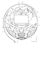
前枠2の前面には窓枠11が装着されている。この窓枠11は円形孔状の窓部12を有するものであり、窓部12の内周面には透明なガラス窓13が固定されている。この窓枠11の後面には左上隅部および右上隅部に位置してスピーカ14が固定されており、各スピーカ14の前方には網状のスピーカカバー15が配置されている。これら各スピーカカバー15は窓枠11に固定されたものであり、各スピーカ14が再生する遊技音は前方のスピーカカバー15を通して放出される。窓枠11には両スピーカ14間に位置してランプカバー16が固定されており、ランプカバー16の後方には複数の電飾LED17が配置されている。これら各電飾LED17は窓枠11に固定されたものであり、ランプカバー16は電飾LED17が発光することに基いて後方から照明される。
A window frame 11 is mounted on the front surface of the front frame 2. This window frame 11 has a circular hole-shaped window portion 12, and a transparent glass window 13 is fixed to the inner peripheral surface of the window portion 12. Speakers 14 are fixed to the rear surface of the window frame 11 at the upper left corner and the upper right corner, and a net-like speaker cover 15 is disposed in front of each speaker 14. Each speaker cover 15 is fixed to the window frame 11, and the game sound reproduced by each speaker 14 is emitted through the front speaker cover 15. A lamp cover 16 is fixed to the window frame 11 between both speakers 14, and a plurality of illumination LEDs 17 are arranged behind the lamp cover 16. Each of these illumination LEDs 17 is fixed to the window frame 11, and the lamp cover 16 is illuminated from behind based on the fact that the illumination LEDs 17 emit light.
前枠2には、図2に示すように、遊技盤18が装着されており、遊技盤18は窓枠11のガラス窓13により前方から覆われている。この遊技盤18の前面には外レール19および内レール20が固定されている。これら外レール19および内レール20間には発射通路21が形成されており、打球槌10が弾いた遊技球は発射通路21を通して遊技領域22内に放出される。この遊技領域22内には複数の障害釘23が打込まれており、遊技領域22内に放出された遊技球は障害釘23に当りながら遊技領域22内を落下する。この遊技領域22は外レール19および内レール20によって囲まれた円形領域(発射通路21の残余領域)を称するものであり、遊技球が転動可能な最大範囲である転動領域に相当する。
As shown in FIG. 2, a game board 18 is attached to the front frame 2, and the game board 18 is covered from the front by the glass window 13 of the window frame 11. An outer rail 19 and an inner rail 20 are fixed to the front surface of the game board 18. A launch passage 21 is formed between the outer rail 19 and the inner rail 20, and the game ball that is hit by the hitting ball 10 is discharged into the game area 22 through the launch passage 21. A plurality of obstacle nails 23 are driven into the game area 22, and the game balls released into the game area 22 fall within the game area 22 while hitting the obstacle nails 23. This game area 22 refers to a circular area surrounded by the outer rail 19 and the inner rail 20 (the remaining area of the launch passage 21), and corresponds to a rolling area that is the maximum range in which the game ball can roll.
遊技領域22内には上面が開口するポケット状の特別図柄始動口24が固定されている。この特別図柄始動口24内には近接スイッチからなる特別図柄始動センサ25(図3参照)が固定されており、特別図柄始動センサ25は特別図柄始動口24内に遊技球が入賞したことを検出して特別図柄始動信号を出力する。この特別図柄始動口24は始動口に相当するものであり、特別図柄始動センサ25は始動球検出器に相当するものである。
A pocket-shaped special symbol starting port 24 whose upper surface is open is fixed in the game area 22. A special symbol start sensor 25 (see FIG. 3) consisting of a proximity switch is fixed in the special symbol start port 24, and the special symbol start sensor 25 detects that a game ball has won a prize in the special symbol start port 24. Then, a special symbol start signal is output. The special symbol start port 24 corresponds to a start port, and the special symbol start sensor 25 corresponds to a start ball detector.
遊技領域22内には、図2に示すように、入賞口台板26が固定されており、入賞口台板26には前面が開口する四角筒状の大入賞口27が固定されている。この大入賞口27内には近接スイッチからなるカウントセンサ28(図3参照)が固定されており、カウントセンサ28は遊技球が大入賞口27内に入賞したことを検出してカウント信号を出力する。この大入賞口27は可変入球口に相当するものである。
As shown in FIG. 2, a prize opening base plate 26 is fixed in the game area 22, and a square cylindrical large winning opening 27 whose front surface is open is fixed to the prize opening base plate 26. A count sensor 28 (see FIG. 3) comprising a proximity switch is fixed in the special winning opening 27, and the count sensor 28 detects that a game ball has won the special winning opening 27 and outputs a count signal. To do. The big winning opening 27 corresponds to a variable entrance.
入賞口台板26には、図2に示すように、扉29が下端部の水平な軸30を中心に回動可能に装着されている。この扉30は大入賞口ソレノイド31(図3参照)のプランジャに連結されており、大入賞口ソレノイド31は扉29を垂直状態に回動操作することに基づいて大入賞口27の前面を遊技球が入賞不能に閉鎖し、扉29を前方へ倒れた水平状態に回動操作することに基づいて大入賞口27の前面を遊技球が入賞可能に開放する。即ち、大入賞口27は遊技球が入賞不能な閉鎖状態および遊技球が入賞可能な開放状態に切換わるものである。
As shown in FIG. 2, a door 29 is attached to the winning prize base plate 26 so as to be rotatable about a horizontal shaft 30 at the lower end. The door 30 is connected to a plunger of a special winning opening solenoid 31 (see FIG. 3), and the special winning opening solenoid 31 plays a game on the front of the special winning opening 27 based on turning the door 29 in a vertical state. The ball is closed so that it cannot be won, and the front of the big winning opening 27 is opened so that the game ball can win based on the turning operation of the door 29 in a horizontal state where the door 29 falls forward. In other words, the big winning opening 27 is switched between a closed state in which the game balls cannot be won and an open state in which the game balls can be won.
遊技領域22内には、図2に示すように、表示台板32が固定されており、表示台板32には特別図柄表示器33が固定されている。この特別図柄表示器33はLED表示器から構成されたものであり、特別図柄表示器33には特別図柄が表示される。表示台板32には図柄表示器に相当する装飾図柄表示器34が固定されている。この装飾図柄表示器34は特別図柄表示器33に比べて大きな表示領域を有するカラー液晶表示器から構成されたものであり、装飾図柄表示器34には識別図柄に相当する装飾図柄が表示される。この装飾図柄は左列の図柄要素と中列の図柄要素と右列の図柄要素からなるものであり、左列の図柄要素は第1の図柄要素に相当し、右列の図柄要素は第2の図柄要素に相当し、中列の図柄要素は第3の図柄要素に相当する。
2.電気的構成の説明
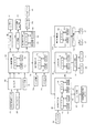
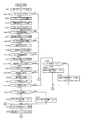
図3のメイン制御回路50はゲーム内容を制御する最上位の制御手段であり、CPU51とROM52とRAM53を有している。このメイン制御回路50のROM52には制御プログラムおよび制御データが記録されており、CPU51はRAM53をワークエリアとしてROM52の制御プログラムおよび制御データに基いて制御動作を実行する。このメイン制御回路50は当落判定手段および変動情報選択手段に相当するものである。
As shown in FIG. 2, a display base plate 32 is fixed in the game area 22, and a special symbol display 33 is fixed to the display base plate 32. The special symbol display 33 is composed of an LED display, and the special symbol display 33 displays a special symbol. A decorative symbol display 34 corresponding to a symbol display is fixed to the display base plate 32. The decorative symbol display 34 is composed of a color liquid crystal display having a larger display area than the special symbol display 33, and the decorative symbol display 34 displays a decorative symbol corresponding to the identification symbol. . This decorative symbol is composed of a symbol element in the left column, a symbol element in the middle column, and a symbol element in the right column. The symbol element in the left column corresponds to the first symbol element, and the symbol element in the right column is the second symbol element. The symbol element in the middle row corresponds to the third symbol element.
2. Description of Electrical Configuration The main control circuit 50 in FIG. 3 is the highest-level control means for controlling the game content, and has a CPU 51, ROM 52 and RAM 53. A control program and control data are recorded in the ROM 52 of the main control circuit 50, and the CPU 51 executes a control operation based on the control program and control data in the ROM 52 using the RAM 53 as a work area. The main control circuit 50 corresponds to a winning determination unit and a variation information selection unit.
出力回路54は特別図柄始動センサ25からの特別図柄始動信号およびカウントセンサ28からのカウント信号を波形成形してメイン制御回路50に出力するものであり、メイン制御回路50は出力回路54からの特別図柄始動信号およびカウント信号のいずれかを検出することに基いて賞球コマンドを設定する。タイマ回路55はメイン制御回路50に一定の時間間隔「4msec」でパルス信号を出力するものであり、メイン制御回路50はタイマ回路55からのパルス信号を検出する毎に処理動作を実行する。
The output circuit 54 shapes the special symbol start signal from the special symbol start sensor 25 and the count signal from the count sensor 28 and outputs the waveform to the main control circuit 50. The main control circuit 50 outputs a special signal from the output circuit 54. A prize ball command is set based on detecting either the symbol start signal or the count signal. The timer circuit 55 outputs a pulse signal to the main control circuit 50 at a constant time interval “4 msec”, and the main control circuit 50 executes a processing operation every time the pulse signal from the timer circuit 55 is detected.
ソレノイド回路56は大入賞口ソレノイド31を通断電するものであり、メイン制御回路50はソレノイド回路56を駆動制御することに基いて大入賞口27の扉29を開閉操作する。LED回路57は特別図柄表示器33に特別図柄を表示するものであり、メイン制御回路50はLED回路57を駆動制御することに基いて特別図柄表示器33の表示内容を制御する。
The solenoid circuit 56 cuts off the power of the special winning opening solenoid 31, and the main control circuit 50 opens and closes the door 29 of the special winning opening 27 based on driving control of the solenoid circuit 56. The LED circuit 57 displays a special symbol on the special symbol display 33, and the main control circuit 50 controls the display content of the special symbol display 33 based on driving control of the LED circuit 57.
払出制御回路60は賞品球の払出動作を制御するものであり、CPU61とROM62とRAM63を有している。この払出制御回路60のROM62には制御プログラムおよび制御データが記録されており、CPU61はRAM63をワークエリアとしてROM62の制御プログラムおよび制御データに基いて遊技球の払出動作を実行する。この払出制御回路60はメイン制御回路50から賞球コマンドが送信されるものであり、賞球コマンドを検出することに基いて駆動信号を設定する。
The payout control circuit 60 controls the payout operation of the prize balls, and has a CPU 61, a ROM 62, and a RAM 63. A control program and control data are recorded in the ROM 62 of the payout control circuit 60, and the CPU 61 executes a payout operation of the game ball based on the control program and control data in the ROM 62 using the RAM 63 as a work area. The payout control circuit 60 receives a prize ball command from the main control circuit 50, and sets a drive signal based on detecting the prize ball command.
モータ回路64は払出制御回路60から駆動信号の設定結果が与えられるものであり、払出制御回路60からの駆動信号に基いてステッピングモータ65に駆動用のパルス信号を与える。このステッピングモータ65は遊技球を上皿6内に賞品球として払出す賞球払出装置の駆動源に相当するものであり、上皿6内にはステッピングモータ65が駆動することに基いて賞球コマンドに応じた個数の賞品球が払出される。
The motor circuit 64 is provided with a drive signal setting result from the payout control circuit 60, and supplies a driving pulse signal to the stepping motor 65 based on the drive signal from the payout control circuit 60. The stepping motor 65 corresponds to a drive source of a prize ball payout device for paying out game balls as prize balls into the upper plate 6. The upper balls 6 have prize balls based on the driving of the stepping motor 65. The number of prize balls according to the command is paid out.
演出制御回路70は装飾図柄遊技の演出内容を総括的に制御するものであり、CPU71とROM72とRAM73を有している。この演出制御回路70のROM72には制御プログラムおよび制御データが記録されており、CPU71はRAM73をワークエリアとしてROM72の制御プログラムおよび制御データに基いて処理動作を実行する。この演出制御回路70はメイン制御回路50からコマンドが送信されるものであり、メイン制御回路50からのコマンドを検出することに基いてコマンドを設定する。この演出制御回路70は予告判定手段および間隔選択手段に相当するものである。
The effect control circuit 70 comprehensively controls the effect contents of the decorative symbol game, and includes a CPU 71, a ROM 72, and a RAM 73. A control program and control data are recorded in the ROM 72 of the effect control circuit 70, and the CPU 71 executes a processing operation based on the control program and control data in the ROM 72 using the RAM 73 as a work area. The effect control circuit 70 receives a command from the main control circuit 50 and sets the command based on detecting the command from the main control circuit 50. The effect control circuit 70 corresponds to a notice determination unit and an interval selection unit.
タイマ回路74は演出制御回路70に一定の時間間隔「4msec」でパルス信号を出力するものであり、演出制御回路70はタイマ回路74からのパルス信号を検出する毎に処理動作を実行する。ストップスイッチ75は上皿6に装着された自己復帰形の押しボタンスイッチからなるものであり、演出制御回路70はストップスイッチ75のオンオフに基づいてストップスイッチ75の操作の有無を判断する。このストップスイッチ75は操作手段に相当するものである。
The timer circuit 74 outputs a pulse signal at a constant time interval “4 msec” to the effect control circuit 70, and the effect control circuit 70 executes a processing operation every time the pulse signal from the timer circuit 74 is detected. The stop switch 75 is a self-returning pushbutton switch mounted on the upper plate 6, and the effect control circuit 70 determines whether or not the stop switch 75 is operated based on whether the stop switch 75 is on or off. This stop switch 75 corresponds to an operating means.
図柄制御回路80はCPU81とROM82とRAM83とVDP84とVROM85とVRAM86を有している。この図柄制御回路80のCPU81は演出制御回路70からのコマンドに基いて制御データを設定し、制御データの設定結果に応じたビデオデータの選択をVDP84に指示するものであり、VDP84は指示内容に応じたビデオデータをVROM85から選択し、ビデオデータの選択結果に基いて表示信号を生成する。このVDP84は表示信号の設定結果をLCD回路87に送信するものであり、LCD回路87はVDP84からの表示信号に応じた映像を装飾図柄表示器34に表示する。これらCPU81およびVDP84の一連の動作はROM82に記録された制御プログラムおよび制御データに基いて行われるものであり、RAM83およびVRAM85はCPU81およびVDP84のワークメモリとして機能する。タイマ回路88は図柄制御回路80に一定の時間間隔「4msec」でパルス信号を出力するものであり、図柄制御回路80はタイマ回路88からのパルス信号を検出する毎に処理動作を実行する。この図柄制御回路80は図柄遊技手段に相当するものである。
The symbol control circuit 80 includes a CPU 81, a ROM 82, a RAM 83, a VDP 84, a VROM 85, and a VRAM 86. The CPU 81 of the symbol control circuit 80 sets control data based on a command from the effect control circuit 70, and instructs the VDP 84 to select video data in accordance with the control data setting result. The corresponding video data is selected from the VROM 85, and a display signal is generated based on the selection result of the video data. The VDP 84 transmits the display signal setting result to the LCD circuit 87, and the LCD circuit 87 displays an image corresponding to the display signal from the VDP 84 on the decorative design display 34. A series of operations of the CPU 81 and the VDP 84 are performed based on a control program and control data recorded in the ROM 82, and the RAM 83 and the VRAM 85 function as work memories for the CPU 81 and the VDP 84. The timer circuit 88 outputs a pulse signal to the symbol control circuit 80 at a constant time interval “4 msec”, and the symbol control circuit 80 executes a processing operation every time the pulse signal from the timer circuit 88 is detected. The symbol control circuit 80 corresponds to symbol game means.
音制御回路90はCPU91とROM92とRAM93を有している。この音制御回路90のCPU91は演出制御回路70からのコマンドに応じた音データをROM92から選択し、音データの選択結果に基いて音信号を生成してスピーカ回路94に送信するものであり、スピーカ回路94は音信号に応じた音を両スピーカ14から出力する。このCPU91の一連の動作はROM92に記録された制御プログラムおよび制御データに基いて行われるものであり、RAM93はCPU91のワークメモリとして機能する。
The sound control circuit 90 includes a CPU 91, a ROM 92 and a RAM 93. The CPU 91 of the sound control circuit 90 selects sound data corresponding to the command from the effect control circuit 70 from the ROM 92, generates a sound signal based on the selection result of the sound data, and transmits it to the speaker circuit 94. The speaker circuit 94 outputs sound corresponding to the sound signal from both speakers 14. The series of operations of the CPU 91 is performed based on the control program and control data recorded in the ROM 92, and the RAM 93 functions as a work memory for the CPU 91.
電飾制御回路100はCPU101とROM102とRAM103を有している。この電飾制御回路100のCPU101は演出制御回路70からのコマンドに応じた電飾データをROM102から選択し、電飾データの選択結果に基いて電飾信号を生成してLED回路104に送信するものであり、LED回路104は電飾LED17を電飾信号に応じた内容で発光させる。このCPU101の一連の動作はROM102に記録された制御プログラムおよび制御データに基いて行われるものであり、RAM103はCPU101のワークメモリとして機能する。
3.遊技機能の説明
3−1.特別図柄遊技機能
遊技者が上皿6内に遊技球を投入して発射ハンドル8を回動操作すると、遊技盤18内に遊技球が発射され、障害釘23に当りながら落下する。この遊技球が特別図柄始動口24内に入賞すると、賞球払出装置から設定個数の遊技球が上皿6内に賞品球として払出され、しかも、特別図柄遊技が開始される。この特別図柄遊技は特別図柄表示器33に特別図柄を変動状態および変動停止状態で順に表示するものであり、特別図柄の変動停止時の態様には外れの態様と通常大当りの態様と確変大当りの態様の3種類が設定されている。
3−2.大当り遊技機能
特別図柄表示器33に特別図柄が通常大当りの態様および確変大当りの態様のいずれかで停止表示されたときには大当り遊技が開始される。この大当り遊技は大入賞口27を開放し、大入賞口27内に遊技球が入賞することを許容する遊技者有利の状態を発生させるものであり、大入賞口27は上限値「10個」の遊技球が入賞する個数条件または開放時間が上限値「30sec」に達する時間条件が満足されるまで開放状態に保持される。この大入賞口27の個数条件および時間条件を基準とする開閉動作は大当りラウンドと称されるものであり、大当りラウンドは固定的な設定回数「15回」だけ繰返される。この大当りラウンドの繰返しは大当り遊技に相当するものであり、各回の大当りラウンド中には装飾図柄表示器34に大当りラウンド表示が行われ、大当りラウンド表示中には両スピーカ14から表示内容に連動して遊技音が出力され、複数の電飾LED17が表示内容に連動して発光する。
3−3.特別図柄遊技保留機能
特別図柄遊技を即座に開始できない特別図柄遊技中および大当り遊技中に遊技球が特別図柄始動口24内に入賞したときには特別図柄遊技が保留される。この特別図柄遊技の保留回数には上限値が設定されており、保留回数が上限値に到達した状態で遊技球が特別図柄始動口24内に入賞したときには特別図柄遊技が保留されない。この特別図柄遊技が保留されない遊技球の入賞を無効な入賞と称し、特別図柄遊技が保留される入賞を有効な入賞と称する。
3−4.装飾図柄遊技機能(図柄遊技機能)
遊技球が特別図柄始動口24内に入賞したときには特別図柄遊技に連動して装飾図柄遊技が開始される。この装飾図柄遊技はビデオデータを再生することに基いて装飾図柄表示器34に動画面を表示し、両スピーカ14から動画面の表示内容に応じた遊技音を出力し、複数の電飾LED17を動画面の表示内容に応じて発光させることで組成されるものであり、装飾図柄遊技の概略は次の通りである。
The illumination control circuit 100 includes a CPU 101, a ROM 102, and a RAM 103. The CPU 101 of the illumination control circuit 100 selects illumination data corresponding to the command from the effect control circuit 70 from the ROM 102, generates an illumination signal based on the selection result of the illumination data, and transmits it to the LED circuit 104. In other words, the LED circuit 104 causes the illumination LED 17 to emit light with contents corresponding to the illumination signal. The series of operations of the CPU 101 is performed based on the control program and control data recorded in the ROM 102, and the RAM 103 functions as a work memory of the CPU 101.
3. Explanation of gaming functions 3-1. Special Symbol Game Function When a player inserts a game ball into the upper plate 6 and rotates the launch handle 8, the game ball is launched into the game board 18 and falls while hitting the obstacle nail 23. When this game ball wins in the special symbol start opening 24, a set number of game balls are paid out as prize balls in the upper plate 6 from the prize ball payout device, and the special symbol game is started. In this special symbol game, special symbols are displayed in order on the special symbol display 33 in a variable state and a variable stop state. Three types of modes are set.
3-2. Big hit game function When the special symbol is stopped and displayed on the special symbol display 33 in either the normal big hit mode or the probability variable big hit mode, the big hit game is started. This big hit game is to open the grand prize winning hole 27 and generate an advantageous state for the player to allow a game ball to win in the big prize winning hole 27. The big winning prize hole 27 has an upper limit value “10”. The game ball is held in the open state until the number condition for the game balls to win or the time condition for the open time to reach the upper limit “30 sec” is satisfied. The opening / closing operation based on the number condition and the time condition of the big prize opening 27 is called a big hit round, and the big hit round is repeated a fixed set number of times “15”. The repetition of the big hit round is equivalent to the big hit game. During each big hit round, the big hit round is displayed on the decorative symbol display 34, and during the big hit round display, both speakers 14 are linked to the display contents. A game sound is output, and the plurality of illumination LEDs 17 emit light in conjunction with display contents.
3-3. Special symbol game hold function When a game ball wins in the special symbol start port 24 during a special symbol game in which a special symbol game cannot be started immediately or during a big hit game, the special symbol game is held. An upper limit value is set for the number of times this special symbol game is held, and the special symbol game is not held when the game ball wins in the special symbol start port 24 with the number of times the hold has reached the upper limit value. A winning of a game ball in which the special symbol game is not held is referred to as an invalid winning, and a winning in which the special symbol game is held is referred to as an effective winning.
3-4. Decorative design game function (design game function)
When the game ball wins in the special symbol start opening 24, the decorative symbol game is started in conjunction with the special symbol game. This decorative symbol game displays a moving image on the decorative symbol display 34 based on the reproduction of video data, outputs game sounds according to the display contents of the moving image from both speakers 14, and turns on the plurality of illumination LEDs 17 It is composed by emitting light according to the display content of the moving image surface, and the outline of the decorative design game is as follows.
装飾図柄表示器34には装飾図柄の左列の図柄要素と中列の図柄要素と右列の図柄要素が静止状態で表示されており、3列の図柄要素は特別図柄の変動開始に同期して変動開始し、遊技者には3列の図柄要素の変動停止状態での組合せによって確変大当りと通常大当りと外れが報知される。この変動とは予め決められた順序で相互に間隔を置いて一列に並ぶ複数種の図柄要素をこれの配列方向に沿って表示範囲が移動するように表示するものであり、各列の図柄要素は上から下へ移動しながら種類が変化する。左列の図柄要素の可変順序および中列の図柄要素の可変順序は同一の「1」→「2」→「3」…「7」→「8」→「1」…のループ状に設定され、右列の図柄要素の可変順序は左列および中列とは逆の「8」→「7」→「6」…「2」→「1」→「8」…のループ状に設定され、各列の図柄要素相互間の間隔にはブランク図柄「B」が挿入されている。このブランク図柄「B」は図柄要素相互間が間隔を置いて並んでいることを報知するものであり、左列の図柄要素のブランク図柄を含む可変順序および中列の図柄要素のブランク図柄を含む可変順序は同一の「1」→「B」→「2」→「B」→「3」→「B」…「7」→「B」→「8」→「B」→「1」…のループ状に設定され、右列の図柄要素のブランク図柄を含む可変順序は左列および中列とは逆の「8」→「B」→「7」→「B」→「6」→「B」…「2」→「B」→「1」→「B」→「8」…のループ状に設定されている。
3−5.目押し演出機能
左列の図柄要素が変動開始直後に高速変動状態から低速変動状態に切換わったときにはブランク図柄に変えて予告図柄111が挿入され、左列の図柄要素が予告図柄111の挿入状態で2周分だけ低速度で変動する。この左列の図柄要素は予告図柄111の挿入状態で低速変動状態から中速変動状態に切換わり、メッセージの図柄113が表示される。このメッセージの図柄113は予告図柄111を狙ってストップスイッチ75を操作することを遊技者に促す報知図柄に相当するものであり、遊技者がストップスイッチ75を限度時間内で予告図柄111を狙って正確に操作したときには予告図柄111が停止表示され、予告図柄111を狙って正確に操作しなかったときには予告図柄111が停止表示されない。この予告図柄111は予告演出として低速変動状態で表示されるものであり、予告図柄111が低速変動状態で表示されたときには装飾図柄が高確率で大当りの組合せになり、予告図柄111が低速変動状態で表示されなかったときには装飾図柄が低確率で大当りの組合せになる。
3−6.確率変動機能
確率変動モードは大当りを確率変動モードの無効状態に比べて高い一定確率で判定する高確率モードである。この確率変動モードは装飾図柄が確変大当りの組合せ「111」・「333」・「555」・「777」のいずれかで停止表示されることに基いて有効化されるものであり、装飾図柄が通常大当りの組合せ「222」・「444」・「666」・「888」のいずれかで停止表示されることに基いて無効化される。
4.メイン制御回路50の内部処理
4−1.メイン処理
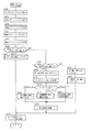
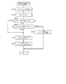
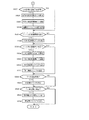
メイン制御回路50のCPU51は電源が投入されると、図4のステップS1の電源投入処理でRAM53の全データを初期設定し、ステップS2でタイマ割込フラグの設定状態を判断する。このタイマ割込フラグはCPU51がタイマ回路55からのパルス信号を受信することに基いてタイマ割込処理でオンするものであり、CPU51はステップS2でタイマ割込フラグのオンを検出したときにはステップS3へ移行し、タイマ割込フラグをオフする。
The decorative symbol display 34 displays the symbol elements in the left column, the middle column, and the right column of the decorative symbols in a stationary state. The symbol elements in the three columns are synchronized with the start of the change of the special symbol. Fluctuation starts, and the player is notified of the probable big hit, the normal big hit, and the losing by the combination of the three rows of symbol elements in the fluctuation stopped state. This variation is to display a plurality of types of symbol elements arranged in a line at predetermined intervals in a predetermined order so that the display range moves along the arrangement direction of the symbol elements. The type changes while moving from top to bottom. The variable order of the symbol elements in the left column and the variable order of the symbol elements in the middle column are set in the same “1” → “2” → “3”... “7” → “8” → “1”. The variable order of the symbol elements in the right column is set as a loop of “8” → “7” → “6”... “2” → “1” → “8”. A blank symbol “B” is inserted in the space between the symbol elements in each column. This blank symbol “B” informs that the symbol elements are arranged at intervals, and includes a variable sequence including a blank symbol of the left column symbol element and a blank symbol of the middle column symbol element. The variable order is the same “1” → “B” → “2” → “B” → “3” → “B” ... “7” → “B” → “8” → “B” → “1”. The variable order including the blank symbols of the symbol elements in the right column is “8” → “B” → “7” → “B” → “6” → “B” opposite to the left column and the middle column. ... “2” → “B” → “1” → “B” → “8”...
3-5. When the symbol elements in the left column are switched from the high-speed fluctuation state to the low-speed fluctuation state immediately after the start of fluctuation, the notice symbol 111 is inserted instead of the blank symbol, and the symbol element in the left column is the insertion state of the notice symbol 111 It fluctuates at a low speed by two laps. The symbol elements in the left column are switched from the low-speed fluctuation state to the medium-speed fluctuation state when the notice symbol 111 is inserted, and a message symbol 113 is displayed. The symbol 113 in this message corresponds to a notification symbol that prompts the player to operate the stop switch 75 aiming at the notice symbol 111, and the player aims at the notice symbol 111 within the time limit for the stop switch 75. When the operation is performed correctly, the notice symbol 111 is stopped and displayed, and when the operation is not performed accurately aiming at the notice symbol 111, the notice symbol 111 is not stopped and displayed. The notice symbol 111 is displayed as a notice effect in a low-speed fluctuation state. When the notice symbol 111 is displayed in a low-speed fluctuation state, the decoration symbol becomes a jackpot combination with a high probability, and the notice symbol 111 is in a low-speed fluctuation state. If it is not displayed, the decorative symbol is a big hit combination with a low probability.
3-6. Stochastic Fluctuation Function The stochastic fluctuation mode is a high probability mode in which the jackpot is determined with a constant probability higher than the invalid state of the probability fluctuation mode. This probability variation mode is activated when the decorative symbol is stopped and displayed in any of the combinations “111”, “333”, “555”, and “777” of the probability variation jackpot. It is invalidated based on the fact that it is stopped and displayed in any of the combinations “222”, “444”, “666”, and “888”.
4). Internal processing of main control circuit 50 4-1. Main Processing When the power is turned on, the CPU 51 of the main control circuit 50 initializes all data in the RAM 53 in the power-on processing in step S1 of FIG. 4, and determines the setting state of the timer interrupt flag in step S2. This timer interrupt flag is turned on in the timer interrupt process based on the CPU 51 receiving a pulse signal from the timer circuit 55. When the CPU 51 detects that the timer interrupt flag is turned on in step S2, step S3 is performed. And the timer interrupt flag is turned off.
CPU51はステップS3でタイマ割込フラグをオフすると、ステップS4の入力処理〜ステップS6のデータ取得処理を順に実行する。このステップS6のデータ取得処理を終えたときにはステップS7の大当り判定処理〜ステップS11の大当り遊技処理をメイン制御フラグの設定状態に基いて択一的に実行し、ステップS2でタイマ割込フラグのオンを新たに検出することに基いてステップS3へ移行する。尚、メイン制御フラグはステップS1の電源投入処理で大当り判定処理に初期設定されるものである。
4−2.入力処理
図5はステップS4の入力処理の詳細を示すものであり、CPU51は図5のステップS21で出力回路54からの特別図柄始動信号の出力状態を判断する。ここで特別図柄始動信号がないことを判断したときにはステップS22で始動信号フラグをオフし、特別図柄始動信号があることを判断したときにはステップS23で始動信号フラグをオンする。即ち、遊技球が特別図柄始動口24内に入賞したときには出力回路54から特別図柄始動信号が出力され、始動信号フラグがオンされる。
4−3.カウンタ更新処理
CPU51は図4のステップS5のカウンタ更新処理へ移行すると、ランダムカウンタR1〜R4の現在の計測値に「1」を加算する。図6はランダムカウンタR1〜R4の加算内容を示すものであり、ランダムカウンタR1〜R4の加算内容は次の通りである。
(1)ランダムカウンタR1は変動パターンを選択する乱数値に相当するものであり、初期値「0」から上限値「100」に加算された後に初期値「0」に戻して循環的に加算される。
(2)ランダムカウンタR2は外れの判定時に判定結果を完全外れおよび外れリーチに振分ける乱数値に相当するものであり、初期値「0」から上限値「49」に加算された後に初期値「0」に戻して循環的に加算される。
(3)ランダムカウンタR3は大当りの発生の有無を抽選する乱数値に相当するものであり、初期値「0」から上限値「328」に加算された後に初期値「0」に戻して循環的に加算される。
(4)ランダムカウンタR4は大当りの判定時に特別図柄の種類を抽選する乱数値に相当するものであり、初期値「0」から上限値「19」に加算された後に初期値「0」に戻して循環的に加算される。
4−4.データ取得処理
図7は図4のステップS6のデータ取得処理の詳細を示すものであり、CPU51は図7のステップS31で始動信号フラグの設定状態を判断する。例えば遊技球が特別図柄始動口24内に入賞したときには図5のスイッチ入力処理で始動信号フラグがオンされている。この場合にはCPU51は図7のステップS31で始動信号フラグのオンを判断し、ステップS32でランダムカウンタR1〜R4の計測値を取得する。
When the CPU 51 turns off the timer interrupt flag in step S3, the CPU 51 sequentially executes the input process in step S4 to the data acquisition process in step S6. When the data acquisition process in step S6 is completed, the big hit determination process in step S7 to the big hit game process in step S11 are executed alternatively based on the set state of the main control flag, and the timer interrupt flag is turned on in step S2. The process proceeds to step S3 based on newly detecting. The main control flag is initially set to the big hit determination process in the power-on process in step S1.
4-2. Input Processing FIG. 5 shows details of the input processing in step S4, and the CPU 51 determines the output state of the special symbol start signal from the output circuit 54 in step S21 in FIG. If it is determined that there is no special symbol start signal, the start signal flag is turned off in step S22. If it is determined that there is a special symbol start signal, the start signal flag is turned on in step S23. That is, when the game ball wins in the special symbol start port 24, a special symbol start signal is output from the output circuit 54, and the start signal flag is turned on.
4-3. Counter Update Processing When the CPU 51 proceeds to the counter update processing in step S5 in FIG. 4, “1” is added to the current measurement values of the random counters R1 to R4. FIG. 6 shows the addition contents of the random counters R1 to R4. The addition contents of the random counters R1 to R4 are as follows.
(1) The random counter R1 corresponds to a random value for selecting a variation pattern, and is added cyclically by returning to the initial value “0” after being added from the initial value “0” to the upper limit value “100”. The
(2) The random counter R2 corresponds to a random value that assigns the determination result to complete detachment and detachment reach at the time of determination of detachment, and is added to the upper limit value “49” from the initial value “0” and then the initial value “ It returns to 0 and is added cyclically.
(3) Random counter R3 corresponds to a random value for drawing whether or not a big hit has occurred, and is added to initial value “0” from initial value “0” and then returned to initial value “0” to circulate Is added to
(4) The random counter R4 corresponds to a random value for drawing a special symbol type when determining the jackpot, and is added from the initial value “0” to the upper limit value “19” and then returned to the initial value “0”. Is added cyclically.
4-4. Data Acquisition Processing FIG. 7 shows details of the data acquisition processing in step S6 of FIG. 4, and the CPU 51 determines the setting state of the start signal flag in step S31 of FIG. For example, when a game ball wins in the special symbol start port 24, the start signal flag is turned on in the switch input process of FIG. In this case, the CPU 51 determines that the start signal flag is turned on in step S31 of FIG. 7, and acquires measured values of the random counters R1 to R4 in step S32.
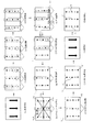
メイン制御回路50のRAM53には、図8に示すように、保留データエリア1〜保留データエリア4が設定されている。これら保留データエリア1〜保留データエリア4はいずれもランダムカウンタR1〜R4の取得結果を保管しておくものであり、CPU51は図7のステップS33へ移行したときには保留データエリア1にランダムカウンタR1〜R4が保管されているか否かを判断する。ここで保留データエリア1にランダムカウンタR1〜R4が保管されていないことを判断したときにはステップS34へ移行し、ランダムカウンタR1〜R4の取得結果を保留データエリア1に記録する。
In the RAM 53 of the main control circuit 50, the reserved data area 1 to the reserved data area 4 are set as shown in FIG. The reserved data area 1 to the reserved data area 4 store the acquisition results of the random counters R1 to R4. When the CPU 51 proceeds to step S33 in FIG. It is determined whether or not R4 is stored. Here, when it is determined that the random counters R1 to R4 are not stored in the hold data area 1, the process proceeds to step S34, and the acquisition results of the random counters R1 to R4 are recorded in the hold data area 1.
CPU51はステップS33で保留データエリア1にランダムカウンタR1〜R4が保管されていることを判断すると、ステップS35で保留データエリア2にランダムカウンタR1〜R4が保管されているか否かを判断する。ここで保留データエリア2にランダムカウンタR1〜R4が保管されていないことを判断したときにはステップS36へ移行し、ランダムカウンタR1〜R4の取得結果を保留データエリア2に記録する。
When the CPU 51 determines that the random counters R1 to R4 are stored in the reserved data area 1 in step S33, the CPU 51 determines whether or not the random counters R1 to R4 are stored in the reserved data area 2 in step S35. If it is determined that the random counters R1 to R4 are not stored in the reserved data area 2, the process proceeds to step S36, and the acquisition results of the random counters R1 to R4 are recorded in the reserved data area 2.
CPU51はステップS35で保留データエリア2にランダムカウンタR1〜R4が格納されていることを判断すると、ステップS37で保留データエリア3にランダムカウンタR1〜R4が保管されているか否かを判断する。ここで保留データエリア3にランダムカウンタR1〜R4が保管されていないことを判断したときにはステップS38へ移行し、ランダムカウンタR1〜R4の取得結果を保留データエリア3に記録する。
When the CPU 51 determines that the random counters R1 to R4 are stored in the reserved data area 2 in step S35, the CPU 51 determines whether or not the random counters R1 to R4 are stored in the reserved data area 3 in step S37. If it is determined that the random counters R1 to R4 are not stored in the reserved data area 3, the process proceeds to step S38, and the acquisition results of the random counters R1 to R4 are recorded in the reserved data area 3.
CPU51はステップS37で保留データエリア3にランダムカウンタR1〜R4が格納されていることを判断すると、ステップS39で保留データエリア4にランダムカウンタR1〜R4が保管されているか否かを判断する。ここで保留データエリ4にランダムカウンタR1〜R4が保管されていないことを判断したときにはステップS40へ移行し、ランダムカウンタR1〜R4の取得結果を保留データエリア4に記録する。即ち、ランダムカウンタR1〜R4の格納数には上限値「4組」が設定されており、上限組のランダムカウンタR1〜R4がRAM53に格納されている状態で遊技球が特別図柄始動口24内に入賞したときにはステップS41でランダムカウンタR1〜R4の取得結果がクリアされ、遊技球が特別図柄始動口24内に入賞したことが無効化される。
4−5.大当り判定処理
CPU51はメイン制御フラグが大当り判定処理にセットされていることを判断すると、図4のステップS6のデータ取得処理からステップS7の大当り判定処理へ移行する。図9はステップS7の大当り判定処理の詳細を示すものであり、CPU51は図9のステップS51で保留データエリア1にランダムカウンタR1〜R4が格納されているか否かを判断する。ここで保留データエリア1にランダムカウンタR1〜R4が格納されていることを判断したときにはステップS52へ移行し、確率変動フラグの設定状態を判断する。この確率変動フラグは確率変動モードの現在の設定状態を示すものであり、CPU51は確率変動モードの有効状態ではステップS52で確率変動フラグのオンを判断してステップS53へ移行し、確率変動モードの無効状態ではステップS52で確率変動フラグのオフを判断してステップS54へ移行する。
When the CPU 51 determines that the random counters R1 to R4 are stored in the reserved data area 3 in step S37, the CPU 51 determines whether or not the random counters R1 to R4 are stored in the reserved data area 4 in step S39. If it is determined that the random counters R1 to R4 are not stored in the hold data area 4, the process proceeds to step S40, and the acquisition results of the random counters R1 to R4 are recorded in the hold data area 4. That is, the upper limit value “4 sets” is set for the number of stored random counters R1 to R4, and the game balls are placed in the special symbol start port 24 in a state where the upper limit set of random counters R1 to R4 are stored in the RAM 53. When winning a prize, the acquisition results of the random counters R1 to R4 are cleared in step S41, and the winning of the game ball in the special symbol starting port 24 is invalidated.
4-5. Big hit determination process When the CPU 51 determines that the main control flag is set to the big hit determination process, the CPU 51 proceeds from the data acquisition process in step S6 in FIG. 4 to the big hit determination process in step S7. FIG. 9 shows details of the big hit determination process in step S7, and the CPU 51 determines whether or not the random counters R1 to R4 are stored in the reserved data area 1 in step S51 of FIG. When it is determined that the random counters R1 to R4 are stored in the reserved data area 1, the process proceeds to step S52, and the setting state of the probability variation flag is determined. The probability variation flag indicates the current setting state of the probability variation mode, and the CPU 51 determines that the probability variation flag is turned on in step S52 in the effective state of the probability variation mode, and proceeds to step S53. In the invalid state, it is determined in step S52 that the probability variation flag is off, and the process proceeds to step S54.
CPU51はステップS53へ移行すると、ROM52から10個の大当り値「7,37,67,97,127,157,187,217,247,277」を選択する。そして、ステップS55で保留データエリア1からランダムカウンタR3の取得結果を検出し、ランダムカウンタR3の検出結果を10個の大当り値「7〜277」と比較する。ここでランダムカウンタR3の検出結果が10個の大当り値「7〜277」のいずれかと同一であることを判断したときには大当りと判定し、ステップS56で大当りフラグをオンする。また、ランダムカウンタR3の検出結果が10個の大当り値「7〜277」のいずれとも相違していることを判断したときには外れと判定し、ステップS64で大当りフラグをオフする。即ち、確率変動モードの有効状態では大当りが「10/329」の高確率で判定される。
When the CPU 51 proceeds to step S53, the ten big hit values “7, 37, 67, 97, 127, 157, 187, 217, 247, 277” are selected from the ROM 52. In step S55, the acquisition result of the random counter R3 is detected from the reserved data area 1, and the detection result of the random counter R3 is compared with ten big hit values “7 to 277”. Here, when it is determined that the detection result of the random counter R3 is the same as any one of the ten big hit values “7 to 277”, the big hit is determined, and the big hit flag is turned on in step S56. Further, when it is determined that the detection result of the random counter R3 is different from any of the ten jackpot values “7 to 277”, it is determined to be off, and the jackpot flag is turned off in step S64. That is, in the effective state of the probability variation mode, the big hit is determined with a high probability of “10/329”.
CPU51はステップS54へ移行すると、ROM52から1個の大当り値「7」を選択する。そして、ステップS55で保留データエリア1からランダムカウンタR3の取得結果を検出し、ランダムカウンタR3の検出結果を1個の大当り値「7」と比較する。ここでランダムカウンタR3の検出結果が1個の大当り値「7」と同一であることを判断したときには大当りと判定し、ステップS56で大当りフラグをオンする。また、ランダムカウンタR3の検出結果が1個の大当り値「7」と相違していることを判断したときには外れと判定し、ステップS64で大当りフラグをオフする。即ち、確率変動モードの無効状態では大当りが「1/329」の低確率で判定される。
When proceeding to step S54, the CPU 51 selects one big hit value “7” from the ROM 52. In step S55, the acquisition result of the random counter R3 is detected from the reserved data area 1, and the detection result of the random counter R3 is compared with one big hit value “7”. Here, when it is determined that the detection result of the random counter R3 is the same as one big hit value “7”, the big hit is determined, and the big hit flag is turned on in step S56. Further, when it is determined that the detection result of the random counter R3 is different from one big hit value “7”, it is determined that it is out, and the big hit flag is turned off in step S64. That is, in the invalid state of the probability variation mode, the big hit is determined with a low probability of “1/329”.
CPU51はステップS56で大当りフラグをオンすると、ステップS57で保留データエリア1からランダムカウンタR4の取得結果を検出し、ランダムカウンタR4の検出結果を10個の確率変動値「0〜9」と比較する。これら10個の確率変動値「0〜9」はいずれもROM52に記録されたものであり、CPU51はステップS57でランダムカウンタR4の検出結果が10個の確率変動値「0〜9」のいずれかと同一であることを判断したときにはステップS58へ移行し、特別図柄を確変大当りの態様(図10参照)に設定する。そして、図9のステップS59で確率変動フラグをオンすることに基づいて確率変動モードを有効化し、ステップS60で演出制御回路70に確変大当りコマンドを送信し、ステップS71でメイン制御フラグに変動パターン設定処理をセットする。
When the big hit flag is turned on in step S56, the CPU 51 detects the acquisition result of the random counter R4 from the reserved data area 1 in step S57, and compares the detection result of the random counter R4 with ten probability variation values “0 to 9”. . These ten probability variation values “0-9” are all recorded in the ROM 52, and the CPU 51 determines that the detection result of the random counter R4 is one of the ten probability variation values “0-9” in step S57. When it is determined that they are the same, the process proceeds to step S58, and the special symbol is set to the probability variation big hit mode (see FIG. 10). Then, the probability variation mode is enabled based on turning on the probability variation flag in step S59 of FIG. 9, a probability variation big hit command is transmitted to the effect control circuit 70 in step S60, and the variation pattern is set in the main control flag in step S71. Set processing.
CPU51はステップS57でランダムカウンタR4の検出結果が10個の確率変動値「0〜9」のいずれとも相違していることを判断すると、ステップS61で特別図柄を通常大当りの態様(図10参照)に設定する。そして、図9のステップS62で確率変動フラグをオフすることに基づいて確率変動モードを無効化し、ステップS63で演出制御回路70に通常大当りコマンドを送信し、ステップS71でメイン制御フラグに変動パターン設定処理をセットする。即ち、確率変動モードは大当りが判定されたことを条件に「1/2」の確率で有効化され、「1/2」の確率で無効化される。
When the CPU 51 determines in step S57 that the detection result of the random counter R4 is different from any of the ten probability variation values “0 to 9”, the special symbol is a normal jackpot in step S61 (see FIG. 10). Set to. Then, the probability variation mode is invalidated based on turning off the probability variation flag in step S62 of FIG. 9, a normal jackpot command is transmitted to the effect control circuit 70 in step S63, and a variation pattern is set in the main control flag in step S71. Set processing. In other words, the probability variation mode is validated with a probability of “½” and invalidated with a probability of “½” on condition that the big hit is determined.
CPU51はステップS64で大当りフラグをオフすると、ステップS65で特別図柄を外れの態様(図10参照)に設定する。そして、図9のステップS66で保留データエリア1からランダムカウンタR2の取得結果を検出し、5個の外れリーチ値「0〜4」と比較する。これら5個の外れリーチ値「0〜4」はいずれもROM52に記録されたものであり、CPU51はステップS66でランダムカウンタR2の検出結果が5個の外れリーチ値「0〜4」のいずれかと同一であることを判断したときには外れリーチと判定し、ステップS67で外れリーチフラグをオンする。次に、ステップS68で演出制御回路70に外れリーチコマンドを送信し、ステップS71でメイン制御フラグに変動パターン設定処理をセットする。
When the CPU 51 turns off the big hit flag in step S64, the special symbol is set in a detachment mode (see FIG. 10) in step S65. In step S66 of FIG. 9, the acquisition result of the random counter R2 is detected from the reserved data area 1 and compared with five outreach reach values “0 to 4”. These five outreach values “0-4” are all recorded in the ROM 52, and the CPU 51 determines that the detection result of the random counter R2 is any one of the five outreach values “0-4” in step S66. When it is determined that they are the same, it is determined that the reach is out of reach, and the out reach reach flag is turned on in step S67. Next, an outreach command is transmitted to the effect control circuit 70 in step S68, and the variation pattern setting process is set in the main control flag in step S71.
CPU51はステップS66でランダムカウンタR2の検出結果が5個の外れリーチ値「0〜4」のいずれとも相違していることを判断すると、完全外れと判定する。そして、ステップS69で外れリーチフラグをオフし、ステップS70で演出制御回路70に完全外れコマンドを送信し、ステップS71でメイン制御フラグに変動パターン設定処理をセットする。
4−6.変動パターン設定処理
CPU51はメイン制御フラグが変動パターン設定処理にセットされていることを検出すると、図4のステップS6のデータ取得処理からステップS8の変動パターン設定処理へ移行する。図11はステップS8の変動パターン設定処理の詳細を示すものであり、CPU51は図11のステップS81で大当りフラグの設定状態を判断する。例えば直前の大当り判定処理で大当りを判定したときにはステップS81で大当りフラグのオンを判断し、ステップS82へ移行する。
When the CPU 51 determines that the detection result of the random counter R2 is different from any of the five outlier reach values “0 to 4” in step S66, the CPU 51 determines that it is completely out. In step S69, the release reach flag is turned off. In step S70, a complete release command is transmitted to the effect control circuit 70. In step S71, the variation pattern setting process is set in the main control flag.
4-6. Fluctuation Pattern Setting Process When the CPU 51 detects that the main control flag is set in the fluctuation pattern setting process, the CPU 51 proceeds from the data acquisition process in step S6 in FIG. 4 to the fluctuation pattern setting process in step S8. FIG. 11 shows the details of the variation pattern setting process in step S8, and the CPU 51 determines the setting state of the big hit flag in step S81 in FIG. For example, when a big hit is determined in the last big hit determination process, it is determined in step S81 that the big hit flag is on, and the process proceeds to step S82.
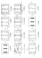
メイン制御回路50のROM52には大当り用の変動パターンテーブルおよび外れリーチ用の変動パターンテーブルが記録されている。これら各変動パターンテーブルはランダムカウンタR1と変動パターンと変動表示時間の相関関係を示すものであり、CPU51はステップS82へ移行したときにはROM52から大当り用の変動パターンテーブルを選択する。そして、ステップS83で保留データエリア1からランダムカウンタR1の取得結果を検出し、大当り用の変動パターンテーブルからランダムカウンタR1の検出結果に応じた大当り用の変動パターンを選択する。図12は大当り用の変動パターンテーブルの記録内容を示すものであり、大当り用の変動パターンテーブルには変動パターンP1〜P4が設定されている。これら変動パターンP1〜P4は変動情報に相当するものであり、変動パターンP1およびP2は所定の変動情報に相当する。
In the ROM 52 of the main control circuit 50, a variation pattern table for big hits and a variation pattern table for outreach are recorded. Each of these fluctuation pattern tables shows the correlation between the random counter R1, the fluctuation pattern, and the fluctuation display time. When the CPU 51 proceeds to step S82, it selects a fluctuation pattern table for big hit from the ROM 52. Then, in step S83, the acquisition result of the random counter R1 is detected from the reserved data area 1, and the big hit variation pattern corresponding to the detection result of the random counter R1 is selected from the big hit variation pattern table. FIG. 12 shows the recorded contents of the variation pattern table for big hits, and variation patterns P1 to P4 are set in the variation pattern table for big hits. These variation patterns P1 to P4 correspond to variation information, and the variation patterns P1 and P2 correspond to predetermined variation information.
CPU51は図11のステップS83で変動パターンを選択すると、ステップS84で図12の大当り用の変動パターンテーブルから変動パターンの選択結果に応じた変動表示時間を選択する。例えばランダムカウンタR1の検出結果が「40」であるときには変動パターン「P1」が選択され、変動パターンの選択結果が「P1」であるときには変動表示時間「16.0sec」が選択される。
When the CPU 51 selects the variation pattern in step S83 of FIG. 11, the CPU 51 selects the variation display time corresponding to the variation pattern selection result from the big hit variation pattern table of FIG. 12 in step S84. For example, when the detection result of the random counter R1 is “40”, the variation pattern “P1” is selected, and when the variation pattern selection result is “P1”, the variation display time “16.0 sec” is selected.
CPU51は直前の大当り判定処理で外れリーチまたは完全外れを判定したときには図11のステップS81で大当りフラグのオフを判断する。そして、ステップS81からステップS85へ移行し、外れリーチフラグの設定状態を判断する。例えば直前の大当り判定処理で外れリーチを判定したときにはステップS85で外れリーチフラグのオンを判断し、ステップS86でROM52から外れリーチ用の変動パターンテーブルを選択する。そして、ステップS87で保留データエリア1からランダムカウンタR1の取得結果を検出し、外れリーチ用の変動パターンテーブルからランダムカウンタR1の検出結果に応じた外れリーチ用の変動パターンを選択する。図13は外れリーチ用の変動パターンテーブルの記録内容を示すものであり、外れリーチ用の変動パターンテーブルには大当り用の変動パターンテーブルとは相違する変動パターンP5〜P8が設定されている。これら変動パターンP5〜P8は変動情報に相当するものであり、変動パターンP5およびP6は所定の変動情報に相当する。
When the CPU 51 determines a missed reach or complete miss in the last big hit determination process, it determines that the big hit flag is off in step S81 of FIG. Then, the process proceeds from step S81 to step S85, and the setting state of the detach reach flag is determined. For example, when the outreach is determined in the last big hit determination process, it is determined in step S85 that the outreach flag is turned on, and the variation pattern table for outreach is selected from the ROM 52 in step S86. In step S87, the acquisition result of the random counter R1 is detected from the hold data area 1, and the fluctuation pattern for outreach according to the detection result of the random counter R1 is selected from the fluctuation pattern table for outlier reach. FIG. 13 shows the recorded contents of the variation pattern table for outreach. In the variation pattern table for outreach, variation patterns P5 to P8 different from the variation pattern table for big hit are set. These fluctuation patterns P5 to P8 correspond to fluctuation information, and the fluctuation patterns P5 and P6 correspond to predetermined fluctuation information.
CPU51は図11のステップS87で外れリーチ用の変動パターンを選択すると、ステップS88で図13の外れリーチ用の変動パターンテーブルから変動パターンの選択結果に応じた変動表示時間を選択する。例えばランダムカウンタR1の検出結果が「10」であるときには変動パターン「P5」が選択され、変動パターンの選択結果が「P5」であるときには変動表示時間「16.0sec」が選択される。
When the CPU 51 selects the variation pattern for outreach in step S87 in FIG. 11, the CPU 51 selects the variation display time corresponding to the selection result of the variation pattern from the variation pattern table for outreach in FIG. For example, when the detection result of the random counter R1 is “10”, the variation pattern “P5” is selected, and when the variation pattern selection result is “P5”, the variation display time “16.0 sec” is selected.
CPU51は直前の大当り判定処理で完全外れを判定したときには図11のステップS85で外れリーチフラグのオフを判断する。そして、ステップS89で変動パターンP91を選択し、ステップS90で変動パターンP9に応じた変動表示時間「2.0sec」を選択する。この変動パターンP9は変動情報に相当するものである。
When the CPU 51 determines that a complete loss has occurred in the previous jackpot determination process, the CPU 51 determines in step S85 in FIG. 11 that the release reach flag is off. In step S89, the fluctuation pattern P91 is selected, and in step S90, the fluctuation display time “2.0 sec” corresponding to the fluctuation pattern P9 is selected. This variation pattern P9 corresponds to variation information.
CPU51は変動パターンおよび変動表示時間を選択すると、ステップS91で変動パターンの選択結果を変動パターンコマンドとして演出制御回路70に送信する。そして、ステップS92で変動表示時間の選択結果を変動時間タイマT1にセットし、ステップS93で保留データエリア1のランダムカウンタR1〜R4をクリアする。
When the CPU 51 selects the variation pattern and the variation display time, the variation pattern selection result is transmitted to the effect control circuit 70 as a variation pattern command in step S91. In step S92, the variable display time selection result is set in the variable time timer T1, and in step S93, the random counters R1 to R4 in the reserved data area 1 are cleared.
CPU51はステップS93で保留データエリア1のランダムカウンタR1〜R4をクリアすると、ステップS94で保留データエリア2の格納データを保留データエリア1にシフトし、ステップS95で保留データエリア3の格納データを保留データエリア2にシフトし、ステップS96で保留データエリア4の格納データを保留データエリア3にシフトする。これら保留データエリア1〜保留データエリア4はランダムカウンタR1等が格納されていない状態でデフォルトデータが記録されるものであり、保留データエリア2〜保留データエリア4にランダムカウンタR1等が格納されているときにはステップS94〜ステップS96でランダムカウンタR1等がシフトされ、ランダムカウンタR1等が格納されていないときにはステップS94〜ステップS96でデフォルトデータがシフトされる。
When the CPU 51 clears the random counters R1 to R4 in the reserved data area 1 in step S93, the stored data in the reserved data area 2 is shifted to the reserved data area 1 in step S94, and the stored data in the reserved data area 3 is reserved in step S95. The data is shifted to the data area 2, and the stored data in the reserved data area 4 is shifted to the reserved data area 3 in step S96. In these reserved data areas 1 to 4, default data is recorded in a state where the random counter R 1 or the like is not stored, and the random counter R 1 or the like is stored in the reserved data area 2 to the reserved data area 4. If the random counter R1 is not stored, the default data is shifted in steps S94 to S96.
CPU51はステップS96で保留データエリア4の格納データを保留データエリア3にシフトすると、ステップS97でメイン制御フラグに特別図柄変動開始処理をセットする。即ち、演出制御回路70には通常大当りと確変大当りと外れリーチと完全外れの判定結果に加え、変動パターンの選択結果が送信される。
4−7.特別図柄変動開始処理
CPU51はメイン制御フラグが特別図柄変動開始処理にセットされていることを検出すると、図4のステップS6のデータ取得処理からステップS9の特別図柄変動開始処理へ移行する。図14はステップS9の特別図柄変動開始処理の詳細を示すものであり、CPU51は図14のステップS101でLED回路57に特別図柄変動開始信号を出力する。すると、LED回路57は特別図柄変動開始信号を検出することに基いて特別図柄の変動表示を開始する。この特別図柄の変動表示は特別図柄を「確変大当りの態様」→「通常大当りの態様」→「外れの態様」→「確変大当りの態様」・・・の設定順序で循環的に可変表示するものである。
When the CPU 51 shifts the stored data in the reserved data area 4 to the reserved data area 3 in step S96, the CPU 51 sets a special symbol variation start process in the main control flag in step S97. In other words, the effect control circuit 70 is transmitted with the selection result of the variation pattern in addition to the determination result of the normal big hit, the probability big hit, the outreach reach and the complete outage.
4-7. Special Symbol Variation Start Process When the CPU 51 detects that the main control flag is set in the special symbol variation start process, the CPU 51 proceeds from the data acquisition process in step S6 in FIG. 4 to the special symbol variation start process in step S9. FIG. 14 shows details of the special symbol variation start process in step S9, and the CPU 51 outputs a special symbol variation start signal to the LED circuit 57 in step S101 in FIG. Then, the LED circuit 57 starts the special symbol variation display based on detecting the special symbol variation start signal. This special symbol variation display is a cyclic display of the special symbol in the setting sequence of “probability of big hit” → “normal big hit” → “outgoing” → “probable big hit”. It is.
CPU51はステップS101で特別図柄変動開始信号を出力すると、ステップS102で演出制御回路70に装飾図柄変動開始コマンドを送信する。そして、ステップS103へ移行し、メイン制御フラグに特別図柄変動停止処理をセットする。この装飾図柄変動開始コマンドは装飾図柄遊技の開始指令に相当するものであり、演出制御回路70は装飾図柄変動開始コマンドを受信することに基いて装飾図柄遊技の映像的な演出を開始することを図柄制御回路80に指示し、装飾図柄遊技の音的な演出を開始することを音制御回路90に指示し、装飾図柄遊技の電飾的な演出を開始することを電飾制御回路100に指示する。
4−8.特別図柄変動停止処理
CPU51はメイン制御フラグが特別図柄変動停止処理にセットされていることを検出すると、図4のステップS6のデータ取得処理からステップS10の特別図柄変動停止処理へ移行する。図15はステップS10の特別図柄変動停止処理の詳細を示すものであり、CPU51は図15のステップS111で変動時間タイマTの計測値から設定値ΔT「4msec」を減算することに基いて特別図柄遊技の残り時間および装飾図柄遊技の残り時間を更新する。そして、ステップS112へ移行し、変動時間タイマTの減算結果を「0」と比較する。
When the CPU 51 outputs the special symbol variation start signal in step S101, the CPU 51 transmits a decorative symbol variation start command to the effect control circuit 70 in step S102. And it transfers to step S103 and sets a special symbol fluctuation | variation stop process to a main control flag. This decoration symbol variation start command is equivalent to a decoration symbol game start command, and the production control circuit 70 starts the visual production of the decoration symbol game based on receiving the decoration symbol variation start command. The design control circuit 80 is instructed, the sound control circuit 90 is instructed to start the sound design of the decorative design game, and the design control circuit 100 is instructed to start the electrical design of the design design game. To do.
4-8. Special Symbol Fluctuation Stop Process When the CPU 51 detects that the main control flag is set in the special symbol fluctuation stop process, the CPU 51 proceeds from the data acquisition process in step S6 in FIG. 4 to the special symbol fluctuation stop process in step S10. FIG. 15 shows the details of the special symbol fluctuation stop process in step S10. The CPU 51 subtracts the set value ΔT “4 msec” from the measured value of the fluctuation time timer T in step S111 in FIG. The remaining time of the game and the remaining time of the decorative symbol game are updated. Then, the process proceeds to step S112, and the subtraction result of the variation time timer T is compared with “0”.
CPU51はステップS112で変動時間タイマTの減算結果が「0」であることを検出すると、特別図柄遊技および装飾図柄遊技の終了を判断し、ステップS113でLED回路57に特別図柄変動停止信号を出力する。この特別図柄変動停止信号は特別図柄の変動表示を大当り判定処理の選択結果で停止することを指示するものであり、大当り判定処理で確変大当りが判定されたときには特別図柄が図10の確変大当りの態様で停止表示され、大当り判定処理で通常大当りが判定されたときには特別図柄が図10の通常大当りの態様で停止表示され、大当り判定処理で外れリーチおよび完全外れが判定されたときには特別図柄が図10の外れの態様で停止表示される。
When the CPU 51 detects that the subtraction result of the variation time timer T is “0” in step S112, the CPU 51 determines the end of the special symbol game and the decorative symbol game, and outputs a special symbol variation stop signal to the LED circuit 57 in step S113. To do. This special symbol fluctuation stop signal instructs to stop the special symbol fluctuation display according to the selection result of the big hit determination process, and when the special variation big hit is determined in the big hit determination processing, the special symbol changes to the positive variation big hit in FIG. The special symbol is stopped and displayed in the normal big hit mode of FIG. 10 when the normal big hit is determined in the big hit determination processing, and the special symbol is displayed when the outreach reach and complete loss are determined in the big hit determination processing. The stop display is performed in the form of 10 deviations.
CPU51は図15のステップS113でLED回路57に特別図柄変動停止信号を出力すると、ステップS114で演出制御回路70に装飾図柄変動停止コマンドを送信する。この装飾図柄変動停止コマンドは装飾図柄遊技の停止指令に相当するものであり、演出制御回路70は装飾図柄変動停止コマンドを検出することに基いて装飾図柄遊技の映像的な演出を停止することを図柄制御回路80に指示し、装飾図柄遊技の音的な演出を停止することを音制御回路90に指示し、装飾図柄遊技の電飾的な演出を停止することを電飾制御回路100に指示する。
When the CPU 51 outputs a special symbol variation stop signal to the LED circuit 57 in step S113 of FIG. 15, the CPU 51 transmits a decorative symbol variation stop command to the effect control circuit 70 in step S114. This decoration symbol variation stop command corresponds to a stop command of the decoration symbol game, and the effect control circuit 70 stops the visual effect of the decoration symbol game based on detecting the decoration symbol variation stop command. Instruct the symbol control circuit 80 to instruct the sound control circuit 90 to stop the sound effect of the decorative symbol game, and instruct the electrical control circuit 100 to stop the electrical effect of the decorative symbol game. To do.
CPU51はステップS114で装飾図柄変動停止コマンドを送信すると、ステップS115で大当りフラグの設定状態を判断する。ここで大当りフラグのオフを判断したときにはステップS116へ移行し、メイン制御フラグに大当り判定処理をセットする。そして、ステップS118で大当りフラグをオフし、ステップS119で外れリーチフラグをオフする。また、ステップS115で大当りフラグのオンを判断したときにはステップS117へ移行し、メイン制御フラグに大当り遊技処理をセットする。そして、ステップS118で大当りフラグをオフし、ステップS119で外れリーチフラグをオフする。
4−9.大当り遊技処理
CPU51はメイン制御フラグが大当り遊技処理にセットされていることを検出すると、図4のステップS6のデータ取得処理からステップS11の大当り遊技処理へ移行する。図16はステップS11の大当り遊技処理の詳細を示すものであり、CPU51は図16のステップS121で大当りラウンドを実行する。この大当りラウンドは大入賞口27を開放する遊技者有利の状態を生成するものであり、大入賞口27内に上限値「10個」の遊技球が入賞したり、あるいは、大入賞口27の開放時間が上限値「30sec」に達することに基づいて終了する。この大当りラウンドはROM52に予め決められ記録された上限値「15回」だけ繰返されるものであり、CPU51はステップS122へ移行したときには大当りラウンドの繰返し回数Rを上限値「15」と比較する。ここで「R=15」を判断したときにはステップS123へ移行し、メイン制御フラグを大当り判定処理にセットする。
5.演出制御回路70の内部処理
5−1.メイン処理
演出制御回路70のCPU71は電源が投入されると、図17のステップS201の電源投入処理でRAM73の全データを初期設定する。そして、ステップS202へ移行し、タイマ割込フラグの設定状態を判断する。このタイマ割込フラグはCPU71がタイマ回路74からのパルス信号を受信することに基いてタイマ割込処理でオンするものであり、CPU71はステップS202でタイマ割込フラグのオフを検出したときにはステップS203のカウンタ更新処理1へ移行し、ステップS202でタイマ割込フラグのオンを検出したときにはステップS204へ移行する。このステップS204でタイマ割込フラグをオフし、ステップS205のカウンタ更新処理2〜ステップS206のコマンド処理を順に実行する。
5−2.INT割込処理
演出制御回路70のCPU71はメイン制御回路50からのストローブ信号(INT信号)を受信すると、INT割込処理を起動する。このストローブ信号はメイン制御回路50がコマンドと共に送信するものであり、CPU71はINT割込処理を起動したときには図18のステップS211でコマンドを受信し、ステップS212でコマンドの受信結果をRAM73に記録する。そして、ステップS213へ移行し、コマンド処理フラグをコマンドの受信結果に応じてセットする。このコマンド処理フラグはステップS201の電源投入処理でコマンド待ち処理に初期設定されるものであり、図19はメイン制御回路50から送信されるコマンドの種類とコマンド処理フラグの設定内容との関係を示している。尚、コマンド待ち処理およびスイッチ入力待ち処理はメイン制御回路50からのコマンドに応じて設定されるものではなく、CPU71が直前の処理内容に応じて設定するものである。
5−3.カウンタ更新処理1
図20はステップS203のカウンタ更新処理1の詳細を示すものであり、CPU71は図20のステップS221でランダムカウンタR11の現在の計測値に「1」を加算する。このランダムカウンタR11は装飾図柄の各列の図柄要素を設定するためのものであり、3桁のカウンタから構成されている。このランダムカウンタR11の1桁目は、図21に示すように、「0」から「7」に加算された後に「0」に戻して循環的に加算され、2桁目は1桁目が「7」から「0」に加算される桁上げ毎に「1」だけ加算され、3桁目は2桁目が「7」から「0」に加算される桁上げ毎に「1」だけ加算される。
When the CPU 51 transmits the decorative symbol variation stop command in step S114, it determines the set state of the big hit flag in step S115. When it is determined that the big hit flag is off, the process proceeds to step S116, and the big hit determination process is set to the main control flag. In step S118, the big hit flag is turned off, and in step S119, the outreach flag is turned off. If it is determined in step S115 that the big hit flag is on, the process proceeds to step S117, and the big hit game process is set in the main control flag. In step S118, the big hit flag is turned off, and in step S119, the outreach flag is turned off.
4-9. Big hit game process When the CPU 51 detects that the main control flag is set to the big hit game process, the CPU 51 shifts from the data acquisition process in step S6 in FIG. 4 to the big hit game process in step S11. FIG. 16 shows the details of the big hit game process in step S11, and the CPU 51 executes the big hit round in step S121 in FIG. This jackpot round generates a player's advantageous state of opening the big winning opening 27, and an upper limit “10” game balls are won in the big winning opening 27, or the big winning opening 27 It ends when the opening time reaches the upper limit “30 sec”. The big hit round is repeated by the upper limit value “15 times” preliminarily determined and recorded in the ROM 52. When the CPU 51 proceeds to step S122, the big hit round repeat count R is compared with the upper limit value “15”. When “R = 15” is determined here, the process proceeds to step S123, and the main control flag is set to the big hit determination process.
5. Internal processing of effect control circuit 70 5-1. Main Process When the power is turned on, the CPU 71 of the effect control circuit 70 initializes all data in the RAM 73 in the power-on process in step S201 of FIG. Then, the process proceeds to step S202, and the setting state of the timer interrupt flag is determined. The timer interrupt flag is turned on in the timer interrupt process based on the CPU 71 receiving the pulse signal from the timer circuit 74. When the CPU 71 detects that the timer interrupt flag is turned off in step S202, the CPU 71 executes step S203. If the timer interrupt flag is detected to be on in step S202, the process proceeds to step S204. In step S204, the timer interrupt flag is turned off, and the command update processing from step S205 to step S206 is sequentially executed.
5-2. INT Interrupt Processing When the CPU 71 of the effect control circuit 70 receives the strobe signal (INT signal) from the main control circuit 50, it starts the INT interrupt processing. The strobe signal is transmitted by the main control circuit 50 together with the command. When the CPU 71 starts the INT interrupt process, the CPU 71 receives the command in step S211 in FIG. 18, and records the command reception result in the RAM 73 in step S212. . Then, the process proceeds to step S213, and the command processing flag is set according to the command reception result. This command processing flag is initially set to command waiting processing in the power-on processing in step S201, and FIG. 19 shows the relationship between the type of command transmitted from the main control circuit 50 and the setting contents of the command processing flag. ing. The command waiting process and the switch input waiting process are not set according to the command from the main control circuit 50, but are set by the CPU 71 according to the immediately preceding process contents.
5-3. Counter update process 1
FIG. 20 shows details of the counter update process 1 in step S203, and the CPU 71 adds “1” to the current measured value of the random counter R11 in step S221 in FIG. This random counter R11 is for setting a symbol element of each column of decorative symbols, and is composed of a three-digit counter. As shown in FIG. 21, the first digit of the random counter R11 is added from “0” to “7”, then returned to “0” and added cyclically, and the second digit is “1”. “1” is added for each carry added from “7” to “0”, and “1” is added for the third digit every time the carry is added from “7” to “0”. The
CPU71は図20のステップS221でランダムカウンタR11を更新すると、ステップS222でランダムカウンタR11の更新結果の1桁目と3桁目とを比較する。ここで両者が相違していることを検出したときにはステップS223へ移行し、ランダムカウンタR11の更新結果をRAM73の完全外れ図柄エリアに格納する。即ち、完全外れ図柄エリアは、図21に示すように、左列および右列が相違する完全外れ図柄の基礎データが格納されるものであり、完全外れ図柄エリアの格納データは次回のステップS223で更新される。
When the CPU 71 updates the random counter R11 in step S221 in FIG. 20, the CPU 71 compares the first digit and the third digit of the update result of the random counter R11 in step S222. If it is detected that the two are different from each other, the process proceeds to step S223, and the update result of the random counter R11 is stored in the completely out of symbol area of the RAM 73. That is, as shown in FIG. 21, the complete out symbol area stores basic data of complete out symbols that are different in the left and right columns. The stored data in the complete out symbol area is stored in the next step S223. Updated.
CPU71は図20のステップS222でランダムカウンタR11の1桁目と3桁目とが同一であることを検出すると、ステップS224でランダムカウンタR11の1桁目と2桁目を比較する。ここで両者が相違していることを検出したときにはステップS225へ移行し、ランダムカウンタR11の更新結果をRAM73の外れリーチ図柄エリアに格納する。即ち、外れリーチ図柄エリアは、図21に示すように、左列および右列が同一で中列が相違する外れリーチ図柄の基礎データが格納されるものであり、外れリーチ図柄エリアの格納データは次回のステップS225で更新される。
5−3.カウンタ更新処理2
CPU71は図17のステップS205のカウンタ更新処理2へ移行すると、ランダムカウンタR12の現在の計測値とランダムカウンタR13の現在の計測値とランダムカウンタR14の現在の計測値に「1」をそれぞれに加算する。ランダムカウンタR12は確変大当り図柄および通常大当り図柄を抽選する乱数値に相当するものであり、初期値「0」から上限値「7」に加算された後に初期値「0」に戻して循環的に加算される。ランダムカウンタR13は予告演出の有無として演出パターンコマンドを選択する乱数値に相当するものであり、初期値「0」から上限値「24」に加算された後に初期値「0」に戻して循環的に加算される。ランダムカウンタR14は予告図柄111の挿入箇所を抽選する乱数値に相当するものであり、初期値「0」から上限値「10」に加算された後に初期値「0」に戻して循環的に加算される。
5−4.コマンド処理
図22はステップS206のコマンド処理の詳細を示すものであり、CPU71はステップS206のコマンド処理ではステップS231のコマンド待ち処理〜ステップS236の装飾図柄変動停止コマンド処理をコマンド処理フラグの設定状態に基いて択一的に行う。
5−4−1.コマンド待ち処理
CPU71はコマンド処理フラグがコマンド待ち処理にセットされていることを検出すると、図21のステップS231のコマンド待ち処理を経て図16のステップS202に復帰する。このコマンド待ち処理はメイン制御回路50からのコマンドを待つ処理であり、実質的な処理動作が行われない。
5−4−2.当落コマンド処理
CPU71はメイン制御回路50からの確変大当りコマンドと通常大当りコマンドと外れリーチコマンドと完全外れコマンドのいずれかを受信すると、コマンド処理フラグに当落コマンド処理をセットする。これら確変大当りコマンド〜完全外れコマンドはいずれも装飾図柄遊技および大当り遊技の双方が行われていない遊技停止状態で送信されるものである。この遊技停止状態ではコマンド処理フラグがコマンド待ち処理にセットされており、CPU71は遊技停止状態で確変大当りコマンド〜完全外れコマンドのいずれかを受信してコマンド処理フラグをコマンド待ち処理から当落コマンド処理に書換える。
When the CPU 71 detects that the first digit and the third digit of the random counter R11 are the same in step S222 in FIG. 20, the CPU 71 compares the first digit and the second digit of the random counter R11 in step S224. If it is detected that the two are different, the process proceeds to step S225, and the update result of the random counter R11 is stored in the outlier reach symbol area of the RAM 73. That is, as shown in FIG. 21, the outreach symbol area stores basic data of outreach symbols with the same left column and right column but different middle columns. It is updated in the next step S225.
5-3. Counter update process 2
When the CPU 71 proceeds to the counter update process 2 in step S205 of FIG. 17, “1” is added to the current measurement value of the random counter R12, the current measurement value of the random counter R13, and the current measurement value of the random counter R14, respectively. To do. The random counter R12 corresponds to a random value for drawing a probability variation jackpot symbol and a normal jackpot symbol, and is added to the upper limit value “7” from the initial value “0” and then returned to the initial value “0” to circulate cyclically. Is added. The random counter R13 corresponds to a random value for selecting an effect pattern command as the presence / absence of the notice effect, and is added to the upper limit value “24” from the initial value “0” and then returned to the initial value “0” to circulate. Is added to The random counter R14 corresponds to a random value for drawing the insertion location of the notice symbol 111. The random counter R14 is added from the initial value “0” to the upper limit value “10”, then returned to the initial value “0” and added cyclically. Is done.
5-4. Command Processing FIG. 22 shows details of the command processing in step S206. In the command processing in step S206, the CPU 71 changes the command wait processing in step S231 to the decorative symbol variation stop command processing in step S236 to the command processing flag setting state. Based on alternatives.
5-4-1. Command Waiting Processing When the CPU 71 detects that the command processing flag is set in the command waiting processing, the CPU 71 returns to step S202 in FIG. 16 through the command waiting processing in step S231 in FIG. This command waiting process is a process of waiting for a command from the main control circuit 50, and no substantial processing operation is performed.
5-4-2. Winning Command Processing When the CPU 71 receives from the main control circuit 50 any of the probabilistic big hit command, the normal big hit command, the miss reach command, or the complete miss command, it sets the win command processing in the command processing flag. Any of these probability variation jackpot commands to complete miss commands is transmitted in a game stop state in which neither the decorative symbol game nor the jackpot game is performed. In this game stop state, the command processing flag is set to the command waiting process, and the CPU 71 receives any one of the probable big hit command and the complete miss command in the game stop state and changes the command processing flag from the command waiting process to the winning command process. rewrite.
CPU71はコマンド処理フラグが当落コマンド処理に設定されていることを検出すると、図23のステップS241でRAM73からコマンドの受信結果を検出する。そして、ステップS242へ移行し、コマンドの検出結果を確変大当りコマンドと比較する。例えばコマンドの検出結果が確変大当りコマンドであることを判断したときにはステップS243へ移行し、装飾図柄を確変大当りの組合せに設定する。このステップS243の処理内容は次の通りである。
When the CPU 71 detects that the command processing flag is set to the current command processing, the CPU 71 detects the command reception result from the RAM 73 in step S241 in FIG. Then, the process proceeds to step S242, where the command detection result is compared with the probability variation jackpot command. For example, when it is determined that the command detection result is a probability variation jackpot command, the process proceeds to step S243, and the decorative symbol is set to a combination of probability variation jackpot. The processing content of step S243 is as follows.
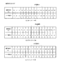
CPU71はランダムカウンタR12の計測値を取得し、ROM72から確変大当り図柄テーブルを検出する。この確変大当り図柄テーブルは、図24に示すように、ランダムカウンタR12と図柄要素の対応関係が記録されたものであり、CPU71はランダムカウンタR12の取得結果に応じた図柄要素を確変大当り図柄テーブルから選択し、左列の図柄要素Lと中列の図柄要素Cと右列の図柄要素Rを同一の図柄要素の選択結果に設定する。例えばランダムカウンタR12の取得結果が「6」であるときには図柄要素として「7」が選択され、左列の図柄要素Lと中列の図柄要素Cと右列の図柄要素Rがいずれも「7」に設定され、装飾図柄が「777」の確変大当りの組合せに設定される。即ち、図24の確変大当り図柄テーブルには図柄要素として「1」・「3」・「5」・「7」の4種類が設定されており、メイン制御回路50が確変大当りを判定したときには装飾図柄が奇数の組合せ「111」・「333」・「555」・「777」のいずれかに設定される。
The CPU 71 acquires the measurement value of the random counter R12 and detects the probability variation big hit symbol table from the ROM 72. As shown in FIG. 24, the probability variation jackpot symbol table is a record of the correspondence between the random counter R12 and symbol elements. The CPU 71 obtains symbol elements according to the acquisition result of the random counter R12 from the probability variation jackpot symbol table. The symbol element L in the left column, the symbol element C in the middle column, and the symbol element R in the right column are set as the selection result of the same symbol element. For example, when the acquisition result of the random counter R12 is “6”, “7” is selected as the symbol element, and the symbol element L in the left column, the symbol element C in the middle column, and the symbol element R in the right column are all “7”. And the decorative symbol is set to a combination of probability variation big hits of “777”. That is, four types of symbol elements “1”, “3”, “5”, and “7” are set in the probability variation jackpot symbol table of FIG. 24, and the decoration is displayed when the main control circuit 50 determines the probability variation jackpot. The symbol is set to one of the odd combinations “111”, “333”, “555”, and “777”.
CPU71は図23のステップS242でコマンドの検出結果が確変大当りコマンドではないことを判断すると、ステップS244でコマンドの検出結果を通常大当りコマンドと比較する。例えばコマンドの検出結果が通常大当りコマンドであることを判断したときにはステップS245へ移行し、装飾図柄を通常大当りの組合せに設定する。このステップS245の処理内容は次の通りである。
If the CPU 71 determines in step S242 in FIG. 23 that the command detection result is not a probability change jackpot command, the CPU 71 compares the command detection result with a normal jackpot command in step S244. For example, when it is determined that the command detection result is a normal jackpot command, the process proceeds to step S245, and the decorative symbol is set to a normal jackpot combination. The processing content of this step S245 is as follows.
CPU71はランダムカウンタR12の計測値を取得し、ROM72から通常大当り図柄テーブルを検出する。この通常大当り図柄テーブルは、図25に示すように、ランダムカウンタR12と図柄要素の対応関係が記録されたものであり、CPU71はランダムカウンタR12の取得結果に応じた図柄要素を通常大当り図柄テーブルから選択し、左列の図柄要素Lと中列の図柄要素Cと右列の図柄要素Rを同一の図柄要素の選択結果に設定する。例えばランダムカウンタR12の取得結果が「6」であるときには図柄要素として「8」が選択され、左列の図柄要素Lと中列の図柄要素Cと右列の図柄要素Rがいずれも「8」に設定され、装飾図柄が「888」の通常大当りの組合せに設定される。即ち、図25の通常大当り図柄テーブルには図柄要素として「2」・「4」・「6」・「8」の4種類が設定されており、メイン制御回路50が通常大当りを判定したときには装飾図柄が偶数の組合せ「222」・「444」・「666」・「888」のいずれかに設定される。
The CPU 71 acquires the measurement value of the random counter R12 and detects the normal jackpot symbol table from the ROM 72. As shown in FIG. 25, the normal jackpot symbol table is a record of the correspondence between the random counter R12 and symbol elements. The CPU 71 obtains symbol elements according to the acquisition result of the random counter R12 from the normal jackpot symbol table. Then, the symbol element L in the left column, the symbol element C in the middle column, and the symbol element R in the right column are set as the selection result of the same symbol element. For example, when the acquisition result of the random counter R12 is “6”, “8” is selected as the symbol element, and the symbol element L in the left column, the symbol element C in the middle column, and the symbol element R in the right column are all “8”. And the decorative symbol is set to a normal jackpot combination of “888”. That is, four types of symbol elements “2”, “4”, “6”, and “8” are set in the normal jackpot symbol table of FIG. 25, and the decoration is displayed when the main control circuit 50 determines the normal jackpot. The combination of an even number of symbols “222”, “444”, “666”, and “888” is set.
CPU71は図23のステップS244でコマンドの検出結果が通常大当りコマンドではないことを判断すると、ステップS246でコマンドの検出結果を外れリーチコマンドと比較する。例えばコマンドの検出結果が外れリーチコマンドであることを判断したときにはステップS247へ移行し、装飾図柄を外れリーチの組合せに設定する。このステップS247の処理内容は次の通りである。
If the CPU 71 determines in step S244 in FIG. 23 that the command detection result is not a normal jackpot command, the CPU 71 detects the command detection result and compares it with a reach command in step S246. For example, when it is determined that the command detection result is an outreach command, the process proceeds to step S247, and the decorative symbol is set as a combination of outreach. The processing content of this step S247 is as follows.
CPU71はRAM73の外れリーチ図柄エリアからランダムカウンタR11の計測値を取得し、ランダムカウンタR11の検出結果の3桁目と2桁目と1桁目に「1」をそれぞれに加算する。そして、左列の図柄要素Lを3桁目の加算結果に設定し、中列の図柄要素Cを2桁目の加算結果に設定し、右列の図柄要素Rを1桁目の加算結果に設定する。例えばランダムカウンタR11として「131」が取得されたときには左列の図柄要素Lおよび右列の図柄要素Rがいずれも「2」に設定され、中列の図柄要素Cが「4」に設定され、装飾図柄が「242」に設定される。即ち、外れリーチ図柄設定処理では装飾図柄が左列の図柄要素Lおよび右列の図柄要素Rが相互に同一で中列の図柄要素Cが相違する外れリーチの組合せに設定される。
The CPU 71 acquires the measurement value of the random counter R11 from the outlier reach design area of the RAM 73, and adds “1” to the third digit, the second digit, and the first digit of the detection result of the random counter R11. Then, the symbol element L in the left column is set as the addition result of the third digit, the symbol element C in the middle column is set as the addition result of the second digit, and the symbol element R of the right column is set as the addition result of the first digit. Set. For example, when “131” is acquired as the random counter R11, the symbol element L in the left column and the symbol element R in the right column are both set to “2”, and the symbol element C in the middle column is set to “4”. The decorative symbol is set to “242”. That is, in the outlier design setting process, the decorative symbol is set to a combination of outliers in which the symbol element L in the left column and the symbol element R in the right column are the same and the symbol element C in the middle column is different.
CPU71は図23のステップS246でコマンドの検出結果が外れリーチコマンドではないことを判断したときには完全外れコマンドであると判断する。この場合にはステップS248へ移行し、装飾図柄を完全外れの組合せに設定する。このステップS248の処理内容は次の通りである。
If the CPU 71 determines in step S246 of FIG. 23 that the command detection result is not a detach command, the CPU 71 determines that the command is a complete detach command. In this case, the process proceeds to step S248, and the decorative design is set to a completely out of combination. The processing content of this step S248 is as follows.
CPU71はRAM73の完全外れ図柄エリアからランダムカウンタR11の計測値を取得し、ランダムカウンタR11の検出結果の3桁目と2桁目と1桁目に「1」をそれぞれに加算する。そして、左列の図柄要素Lを3桁目の加算結果に設定し、中列の図柄要素Cを2桁目の加算結果に設定し、右列の図柄要素Rを1桁目の加算結果に設定する。例えばランダムカウンタR11の取得結果が「112」であるときには左列の図柄要素Lおよび中列の図柄要素Cがいずれも「2」に設定され、右列の図柄要素Rが「3」に設定され、装飾図柄が「223」に設定される。即ち、完全外れ図柄設定処理では装飾図柄が左列の図柄要素Lおよび右列の図柄要素Rが相互に相違する完全外れの組合せに設定される。
The CPU 71 acquires the measurement value of the random counter R11 from the completely out of symbol area of the RAM 73, and adds “1” to the third digit, the second digit, and the first digit of the detection result of the random counter R11. Then, the symbol element L in the left column is set as the addition result of the third digit, the symbol element C in the middle column is set as the addition result of the second digit, and the symbol element R of the right column is set as the addition result of the first digit. Set. For example, when the acquisition result of the random counter R11 is “112”, the symbol element L in the left column and the symbol element C in the middle column are both set to “2”, and the symbol element R in the right column is set to “3”. The decorative design is set to “223”. That is, in the complete removal symbol setting process, the decorative symbol is set to a combination of complete deviation in which the symbol element L in the left column and the symbol element R in the right column are different from each other.
CPU71は図23のステップS249へ移行すると、RAM73に記録されているコマンドの受信結果(確変大当りコマンド,通常大当りコマンド,外れリーチコマンド,完全外れコマンド)をクリアする。そして、ステップS250で左列の図柄要素Lの設定結果と中列の図柄要素Cの設定結果と右列の図柄要素Rの設定結果を図柄制御回路80に送信し、ステップS251でコマンド処理フラグにコマンド待ち処理をセットする。
5−4−3.変動パターンコマンド処理
CPU71はメイン制御回路50からの変動パターンコマンドを受信すると、コマンド処理フラグに変動パターンコマンド処理をセットする。この変動パターンコマンドは確変大当りコマンド〜完全外れコマンドのずれかが送信された直後に送信されるものであり、CPU71はコマンド処理フラグを当落コマンド処理からコマンド待ち処理に書換えた直後にコマンド待ち処理から変動パターンコマンド処理に書換える。
When the CPU 71 proceeds to step S249 in FIG. 23, the command reception result (probability big hit command, normal big hit command, outreach command, complete out command) recorded in the RAM 73 is cleared. In step S250, the setting result of the symbol element L in the left column, the setting result of the symbol element C in the middle column, and the setting result of the symbol element R in the right column are transmitted to the symbol control circuit 80, and the command processing flag is set in step S251. Sets command wait processing.
5-4-3. Fluctuation Pattern Command Processing When the CPU 71 receives a variation pattern command from the main control circuit 50, the CPU 71 sets the variation pattern command processing in the command processing flag. This variation pattern command is transmitted immediately after the deviation between the probabilistic big hit command and the completely off command is transmitted, and the CPU 71 starts the command waiting process immediately after rewriting the command processing flag from the current command process to the command waiting process. Rewrite to change pattern command processing.
CPU71はコマンド処理フラグが変動パターンコマンド処理にセットされていることを判断すると、図26のステップS261でランダムカウンタR13の計測値を取得する。そして、ステップS262でRAM73から変動パターンコマンドの受信結果を検出し、ステップS263へ移行する。
When the CPU 71 determines that the command processing flag is set to the variation pattern command processing, the CPU 71 acquires the measured value of the random counter R13 in step S261 of FIG. In step S262, the reception result of the variation pattern command is detected from the RAM 73, and the process proceeds to step S263.
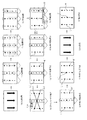
演出制御回路70のROM72には演出テーブルが記録されている。この演出テーブルは、図27に示すように、変動パターンコマンドとランダムカウンタR13と演出パターンコマンドの相関関係を示すものであり、目押し演出用の変動パターンコマンドP1・P2・P3・P5・P6・P7には2種類の演出パターンコマンドが選択肢として設定され、残りの変動パターンコマンドP4・P8・P9には1種類の演出パターンコマンドが選択肢として設定されている。
An effect table is recorded in the ROM 72 of the effect control circuit 70. As shown in FIG. 27, this effect table shows the correlation between the change pattern command, the random counter R13, and the effect pattern command, and the change pattern commands P1, P2, P3, P5, P6, Two types of effect pattern commands are set as options for P7, and one type of effect pattern command is set as an option for the remaining variation pattern commands P4, P8, and P9.
CPU71は図26のステップS263へ移行すると、図27の演出テーブルから変動パターンコマンドの受信結果およびランダムカウンタR13の取得結果に応じた演出パターンコマンドを選択する。例えば変動パターンコマンドとして「P1」が検出され、ランダムカウンタR13として「10」が取得されたときには演出パターンコマンドC1−1が選択される。また、変動パターンコマンドとして「P8」が検出され、ランダムカウンタR13として「20」が取得されたときには演出パターンコマンドC8−1が選択される。
When proceeding to step S263 of FIG. 26, the CPU 71 selects an effect pattern command corresponding to the reception result of the variation pattern command and the acquisition result of the random counter R13 from the effect table of FIG. For example, when “P1” is detected as the variation pattern command and “10” is acquired as the random counter R13, the effect pattern command C1-1 is selected. When “P8” is detected as the variation pattern command and “20” is acquired as the random counter R13, the effect pattern command C8-1 is selected.
CPU71は図26のステップS263で演出パターンコマンドを選択すると、ステップS264でRAM73に記録されている変動パターンコマンドの受信結果をクリアする。そして、ステップS265へ移行し、図柄制御回路80と音制御回路90と電飾制御回路100に演出パターンコマンドの選択結果を送信する。音制御回路90のROM92には複数の音データが記録されており、音制御回路90のCPU91は演出制御回路70からの演出パターンコマンドを受信したときには演出パターンコマンドの受信結果に応じた音データをROM92から選択し、RAM93に記録する。電飾制御回路100のROM102には複数の電飾データが記録されており、電飾制御回路100のCPU101は演出制御回路70からの演出パターンコマンドを受信したときには演出パターンコマンドの受信結果に応じた電飾データをROM102から選択し、RAM103に記録する。
When CPU 71 selects an effect pattern command in step S263 in FIG. 26, CPU 71 clears the reception result of the variation pattern command recorded in RAM 73 in step S264. And it transfers to step S265 and the selection result of a production pattern command is transmitted to the symbol control circuit 80, the sound control circuit 90, and the illumination control circuit 100. A plurality of sound data are recorded in the ROM 92 of the sound control circuit 90, and when the CPU 91 of the sound control circuit 90 receives the effect pattern command from the effect control circuit 70, the sound data corresponding to the reception result of the effect pattern command is obtained. Select from ROM 92 and record in RAM 93. A plurality of illumination data is recorded in the ROM 102 of the illumination control circuit 100. When the CPU 101 of the illumination control circuit 100 receives an effect pattern command from the effect control circuit 70, it corresponds to the reception result of the effect pattern command. The illumination data is selected from the ROM 102 and recorded in the RAM 103.
図柄制御回路80のVROM85には、図28に示すように、複数のビデオデータが記録されている。これら各ビデオデータには演出パターンコマンドが設定されており、図柄制御回路80のCPU81は演出制御回路70からの演出パターンコマンドを受信したときには演出パターンコマンドに応じたビデオデータの種類を選択し、VDP84に送信する。すると、VDP84はCPU81が指定したビデオデータをVROM85から検出し、ビデオデータの検出結果を解凍してVRAM86に記録する。これら各ビデオデータはメイン制御回路50から装飾図柄変動開始コマンドが送信されることを契機に再生開始され、メイン制御回路50から装飾図柄変動停止コマンドが送信されることを契機に再生停止されるものであり、各ビデオデータの再生時間は装飾図柄変動開始コマンドが送信されてから装飾図柄変動停止コマンドが送信されるまでの所要時間である変動表示時間と同一値に設定されている。例えば図28のビデオデータV1は演出制御回路70が演出パターンコマンドC1−1およびC1−2を設定したときに選択されるものであり、演出パターンコマンドC1−1およびC1−2はメイン制御回路50が変動パターンP1を設定したときに選択される。このビデオデータV1の再生時間は変動パターンP1の変動表示時間と同一値「16.0sec」に設定されている。
A plurality of video data are recorded in the VROM 85 of the symbol control circuit 80 as shown in FIG. An effect pattern command is set for each of the video data. When the CPU 81 of the design control circuit 80 receives the effect pattern command from the effect control circuit 70, the video data type corresponding to the effect pattern command is selected, and the VDP 84 To send to. Then, the VDP 84 detects the video data designated by the CPU 81 from the VROM 85, decompresses the video data detection result, and records it in the VRAM 86. Each video data is started to be played when a decoration design variation start command is transmitted from the main control circuit 50, and is stopped when a decoration design variation stop command is transmitted from the main control circuit 50. The reproduction time of each video data is set to the same value as the variation display time, which is the time required from when the decorative symbol variation start command is transmitted until when the decorative symbol variation stop command is transmitted. For example, the video data V1 in FIG. 28 is selected when the effect control circuit 70 sets the effect pattern commands C1-1 and C1-2, and the effect pattern commands C1-1 and C1-2 are selected by the main control circuit 50. Is selected when the variation pattern P1 is set. The reproduction time of the video data V1 is set to the same value “16.0 sec” as the fluctuation display time of the fluctuation pattern P1.
CPU71は図26のステップS265で演出パターンコマンドを送信すると、ステップS266で演出パターンコマンドの選択結果を「C1−2,C2−2,C3−2,C5−2,C6−2,C7−2」と比較する。これら6種類の演出パターンコマンドC1−2〜C7−2はいずれも予告図柄111を挿入することなく目押し演出を発生させるものであり、CPU71はステップS266で演出パターンコマンドの選択結果が6種類の演出パターンコマンドC1−2〜C7−2のいずれとも相違していることを判断したときにはステップS268へ移行する。
When the CPU 71 transmits the effect pattern command in step S265 of FIG. 26, the result of selecting the effect pattern command is “C1-2, C2-2, C3-2, C5-2, C6-2, C7-2” in step S266. Compare with These six types of effect pattern commands C1-2 to C7-2 are all for generating a press effect without inserting the notice symbol 111, and the CPU 71 selects six types of effect pattern commands in step S266. When it is determined that it is different from any of the effect pattern commands C1-2 to C7-2, the process proceeds to step S268.
CPU71はステップS268へ移行すると、演出パターンコマンドの選択結果を「C1−1,C2−1,C3−1,C5−1,C6−1,C7−1」と比較する。これら6種類の演出パターンコマンドC1−1〜C7−1はいずれも予告図柄111を挿入して目押し演出を発生させるものであり、CPU71はステップS268で演出パターンコマンドの選択結果が6種類の演出パターンコマンドC1−1〜C7−1のいずれとも相違していることを判断したときにはステップS276へ移行する。ここで予告無し目押し演出フラグをオフし、ステップS277で予告有り目押し演出フラグをオフし、ステップS278でコマンド処理フラグにコマンド待ち処理をセットする。
In step S268, the CPU 71 compares the selection result of the effect pattern command with “C1-1, C2-1, C3-1, C5-1, C6-1, C7-1”. These six types of effect pattern commands C1-1 to C7-1 are all for inserting a notice symbol 111 to generate a press effect, and the CPU 71 selects six types of effect pattern commands in step S268. When it is determined that it is different from any of the pattern commands C1-1 to C7-1, the process proceeds to step S276. At this point, the unannounced eye-depressing effect flag is turned off, the unannounced eye-depressing effect flag is turned off at step S277, and a command waiting process is set to the command processing flag at step S278.
CPU71はステップS266で演出パターンコマンドの選択結果が予告無し目押し演出用の6種類の演出パターンコマンドC1−2〜C7−2のいずれかと同一であることを判断したときにはステップS267へ移行する。ここで予告無し目押し演出フラグをオンし、ステップS278でコマンド処理フラグにコマンド待ち処理をセットする。
When the CPU 71 determines in step S266 that the selection result of the effect pattern command is the same as any one of the six types of effect pattern commands C1-2 to C7-2 for the announcement without a notice, the process proceeds to step S267. Here, the unannounced eye-depression effect flag is turned on, and a command waiting process is set in the command process flag in step S278.
CPU71はステップS268で演出パターンコマンドの選択結果が予告有り目押し演出用の6種類の演出パターンコマンドC1−1〜C7−1のいずれかと同一であることを判断したときにはステップS269へ移行し、予告有り目押し演出フラグをオンする。そして、ステップS270でランダムカウンタR14の計測値を取得し、ステップS271へ移行する。
When the CPU 71 determines in step S268 that the selection result of the effect pattern command is the same as one of the six types of effect pattern commands C1-1 to C7-1 for the announcement with the advance notice, the process proceeds to step S269. Turn on the presence push effect flag. In step S270, the measurement value of the random counter R14 is acquired, and the process proceeds to step S271.
CPU71はステップS271へ移行すると、演出パターンコマンドの選択結果を検出する。ここで演出パターンコマンドの検出結果が2種類の演出パターンコマンド「C1−1,C5−1」のいずれかと同一であることを判断したときには演出パターンコマンドの検出結果が3ラインリーチ用であると判定し、ステップS272へ移行する。この3ラインリーチとは右下りの有効ラインに沿って左列の図柄要素および右列の図柄要素が同種の数字で停止表示され、水平な有効ラインに沿って左列の図柄要素および右列の図柄要素が同種の数字で停止表示され、右上りの有効ラインに沿って左列の図柄要素および右列の図柄要素が同種の数字で停止表示されたリーチ状態を称する。
CPU71 will detect the selection result of an effect pattern command, if it transfers to step S271. Here, when it is determined that the detection result of the effect pattern command is the same as one of the two types of effect pattern commands “C1-1, C5-1”, it is determined that the detection result of the effect pattern command is for 3-line reach. Then, the process proceeds to step S272. This three-line reach means that the left row of design elements and the right row of design elements are stopped at the same kind of numbers along the right-down active line, and the left row of design elements and the right column of the right row are displayed along the horizontal active line. This means a reach state in which the symbol elements are stopped and displayed with the same type of numbers, and the left and right row of symbol elements are stopped and displayed with the same type of numbers along the upper right effective line.
CPU71はステップS271で演出パターンコマンドの検出結果が2種類の演出パターンコマンド「C2−1,C6−1」のいずれかと同一であることを判断したときには演出パターンコマンドの検出結果が2ラインリーチ用であると判定し、ステップS273へ移行する。この2ラインリーチとは右下りの有効ラインに沿って左列の図柄要素および右列の図柄要素が同種の数字で停止表示され、右上りの有効ラインに沿って左列の図柄要素および右列の図柄要素が同種の数字で停止表示されたリーチ状態を称する。
When the CPU 71 determines in step S271 that the detection result of the effect pattern command is the same as one of the two types of effect pattern commands “C2-1, C6-1”, the detection result of the effect pattern command is for 2-line reach. It is determined that there is, and the process proceeds to step S273. The two-line reach means that the symbol elements in the left column and the symbol elements in the right column are stopped at the same kind of numbers along the right-down effective line, and the symbol elements in the left column and the right column are displayed along the upper-right effective line. The reach state in which the symbol elements are stopped and displayed with the same kind of numbers.
CPU71はステップS271で演出パターンコマンドの検出結果が2種類の演出パターンコマンド「C3−1,C7−1」のいずれかと同一であることを判断したときには演出パターンコマンドの検出結果が1ラインリーチ用であると判定し、ステップS274へ移行する。この1ラインリーチとは水平な有効ラインだけに沿って左列の図柄要素および右列の図柄要素が同種の数字で停止表示されたリーチ状態を称する。
When the CPU 71 determines in step S271 that the effect pattern command detection result is the same as one of the two types of effect pattern commands “C3-1, C7-1”, the effect pattern command detection result is for one line reach. It is determined that there is, and the process proceeds to step S274. This one-line reach refers to a reach state in which the symbol elements in the left column and the symbol elements in the right column are stopped and displayed with the same kind of numbers along only the horizontal effective line.
演出制御回路70のROM72には3ラインリーチ用の予告データと2ラインリーチ用の予告データと1ラインリーチ用の予告データが記録されている。これら各予告データは、図29に示すように、ランダムカウンタR14の計測値「0」〜「10」と図柄番号「A3」・「A7」・「A11」の対応関係を示すものである。これら各図柄番号「A3」・「A7」・「A11」は、図30に示すように、左列の図柄要素および左列のブランク図柄を特定する機能を備えたものであり、図30の図柄番号データは演出制御回路70のROM72および図柄制御回路80のROM82の双方に記録されている。
In the ROM 72 of the effect control circuit 70, notice data for 3 line reach, notice data for 2 line reach, and notice data for 1 line reach are recorded. As shown in FIG. 29, each of these notice data indicates the correspondence between the measurement values “0” to “10” of the random counter R14 and the symbol numbers “A3”, “A7”, and “A11”. Each of these symbol numbers “A3”, “A7”, and “A11” has a function of specifying the symbol element in the left column and the blank symbol in the left column as shown in FIG. The number data is recorded in both the ROM 72 of the effect control circuit 70 and the ROM 82 of the symbol control circuit 80.
CPU71は図26のステップS272へ移行したときにはROM72から図29の(a)の3ラインリーチ用の予告データを選択する。そして、3ラインリーチ用の予告データからランダムカウンタR14の取得結果に応じた図柄番号Aを選択し、図26のステップS275で図柄番号Aの選択結果を図柄制御回路80に予告図柄111の挿入箇所として送信し、ステップS278でコマンド処理フラグにコマンド待ち処理をセットする。例えばランダムカウンタR14の取得結果が「10」であるときには図柄番号Aとして「A11」が選択される。
When the CPU 71 proceeds to step S272 in FIG. 26, the CPU 71 selects the three-line reach notice data in FIG. Then, the symbol number A corresponding to the acquisition result of the random counter R14 is selected from the preview data for the three line reach, and the selection result of the symbol number A is inserted into the symbol control circuit 80 in step S275 of FIG. In step S278, command waiting processing is set in the command processing flag. For example, when the acquisition result of the random counter R14 is “10”, “A11” is selected as the symbol number A.
CPU71は図26のステップS273へ移行したときにはROM72から図29の(b)の2ラインリーチ用の予告データを選択する。そして、2ラインリーチ用の予告データからランダムカウンタR14の取得結果に応じた図柄番号Aを選択し、図26のステップS275で図柄番号Aの選択結果を予告図柄111の挿入箇所として図柄制御回路80に送信し、ステップS278でコマンド処理フラグにコマンド待ち処理をセットする。例えばランダムカウンタR14の取得結果が「10」であるときには図柄番号Aとして「A3」が選択される。
When the CPU 71 proceeds to step S273 in FIG. 26, the CPU 71 selects the two-line reach notice data in FIG. Then, the symbol number A corresponding to the acquisition result of the random counter R14 is selected from the two-line reach preview data, and the symbol control circuit 80 uses the selection result of the symbol number A as the insertion location of the preview symbol 111 in step S275 of FIG. In step S278, command waiting processing is set in the command processing flag. For example, when the acquisition result of the random counter R14 is “10”, “A3” is selected as the symbol number A.
CPU71は図26のステップS274へ移行したときにはROM72から図29の(c)の1ラインリーチ用の予告データを選択する。そして、1ラインリーチ用の予告データからランダムカウンタR14の取得結果に応じた図柄番号Aを選択し、図26のステップS275で図柄番号Aの選択結果を予告図柄111の挿入箇所として図柄制御回路80に送信し、ステップS278でコマンド処理フラグにコマンド待ち処理をセットする。例えばランダムカウンタR14の取得結果が「10」であるときには図柄番号Aとして「A7」が選択される。
5−4−4.装飾図柄変動開始コマンド処理
CPU71はメイン制御回路50からの装飾図柄変動開始コマンドを受信すると、コマンド処理フラグに装飾図柄変動開始コマンド処理をセットする。この装飾図柄変動開始コマンドは変動パターンコマンドが送信された直後に送信されるものであり、CPU71はコマンド処理フラグを変動パターンコマンド処理からコマンド待ち処理に書換えた直後にコマンド待ち処理から装飾図柄変動開始コマンド処理に書換える。
When the CPU 71 proceeds to step S274 in FIG. 26, the CPU 71 selects the one-line reach notice data shown in FIG. Then, the symbol number A corresponding to the acquisition result of the random counter R14 is selected from the notice data for one line reach, and the symbol control circuit 80 uses the selection result of the symbol number A as the insertion position of the notice symbol 111 in step S275 of FIG. In step S278, command waiting processing is set in the command processing flag. For example, when the acquisition result of the random counter R14 is “10”, “A7” is selected as the symbol number A.
5-4-4. Decoration Symbol Variation Start Command Processing When the CPU 71 receives the decoration symbol variation start command from the main control circuit 50, the CPU 71 sets the decoration symbol variation start command processing in the command processing flag. This decoration symbol variation start command is transmitted immediately after the variation pattern command is transmitted, and the CPU 71 starts decoration symbol variation from the command waiting process immediately after rewriting the command processing flag from the variation pattern command process to the command waiting process. Rewrite to command processing.
CPU71はコマンド処理フラグが装飾図柄変動開始コマンド処理にセットされていることを検出すると、図31のステップS281で図柄制御回路80と音制御回路90と電飾制御回路100にスタートコマンドを送信する。そして、ステップS282へ移行し、RAM73に記録されている装飾図柄変動開始コマンドをクリアする。
When the CPU 71 detects that the command processing flag is set in the decorative symbol variation start command processing, the CPU 71 transmits a start command to the symbol control circuit 80, the sound control circuit 90, and the illumination control circuit 100 in step S281 of FIG. Then, the process proceeds to step S282, and the decorative symbol variation start command recorded in the RAM 73 is cleared.
音制御回路90のCPU91は演出制御回路70からのスタートコマンドを受信すると、RAM93の音データを再生することに基いてスピーカ14から音データの選択結果に応じた遊技音を出力する。電飾制御回路100のCPU101は演出制御回路70からのスタートコマンドを受信すると、RAM103の電飾データを再生することに基いて電飾LED17を電飾データの選択結果に応じたパターンで発光させる。
When the CPU 91 of the sound control circuit 90 receives the start command from the effect control circuit 70, the game sound corresponding to the sound data selection result is output from the speaker 14 based on the reproduction of the sound data in the RAM 93. When receiving the start command from the effect control circuit 70, the CPU 101 of the illumination control circuit 100 causes the illumination LED 17 to emit light in a pattern according to the selection result of the illumination data based on reproducing the illumination data in the RAM 103.
図柄制御回路80のCPU81は演出制御回路70からのスタートコマンドを受信すると、VDP84にスタートコマンドを送信する。すると、VDP84はVRAM86のビデオデータを再生することに基いて装飾図柄表示器34にビデオデータに応じた映像を表示し、ビデオデータにキャラクタデータを重ねることに基づいて装飾図柄の各列の図柄要素を変動状態および変動停止状態で表示する。この装飾図柄の変動表示はビデオデータの再生時間内で停止するように行われるものであり、装飾図柄はビデオデータの再生時間内で演出制御回路70の設定結果に応じた組合せで停止表示される。即ち、装飾図柄は3列の変動表示を開始してから変動パターンの選択結果に応じた変動表示時間内で組合せが決まる。
When the CPU 81 of the symbol control circuit 80 receives the start command from the effect control circuit 70, it transmits the start command to the VDP 84. Then, the VDP 84 displays the video according to the video data on the decorative design display 34 based on the reproduction of the video data of the VRAM 86, and the symbol elements of each column of the decorative design based on the superimposition of the character data on the video data. Is displayed in a variable state and a variable stop state. The decorative symbol variation display is performed so as to stop within the playback time of the video data, and the decorative symbol is stopped and displayed within the playback time of the video data in a combination according to the setting result of the effect control circuit 70. . That is, the combination of the decorative symbols is determined within the variation display time corresponding to the variation pattern selection result after starting the three columns of variation display.
CPU71は図31のステップS282で装飾図柄変動開始コマンドをクリアすると、ステップS283で予告無し目押し演出フラグの設定状態を判断し、ステップS284で予告有り目押し演出フラグの設定状態を判断する。予告無し目押し演出フラグは直前の変動パターンコマンド処理で演出パターンコマンドC1−2・C2−2・C3−2・C5−2・C6−2・C7−2の6種類のいずれかが選択されることに基づいてオンされるものであり、予告有り目押し演出フラグは直前の変動パターンコマンド処理で演出パターンコマンドC1−1・C2−1・C3−1・C5−1・C6−1・C7−1の6種類のいずれかが選択されることに基づいてオンされるものであり、CPU71は予告無し目押し演出フラグおよび予告有り目押し演出フラグの双方がオフされていることを判断したときにはステップS285でコマンド処理フラグにコマンド待ち処理をセットする。
When the CPU 71 clears the decorative symbol variation start command in step S282 in FIG. 31, the CPU 71 determines the setting state of the no-presentation effect flag in step S283, and determines the setting state of the notification effect flag in step S284. As for the announcement flag without notice, one of six types of effect pattern commands C1-2, C2-2, C3-2, C5-2, C6-2, and C7-2 is selected in the immediately preceding variation pattern command processing. The advance flag with the advance notice is turned on by the effect pattern command C1-1, C2-1, C3-1, C5-1, C6-1, C7- The CPU 71 is turned on when any one of the six types is selected, and the CPU 71 determines that both the unannounced unattended effect flag and the unattended effect flag flag are off. In S285, command waiting processing is set in the command processing flag.
CPU71は予告無し目押し演出フラグおよび予告有り目押し演出フラグのいずれかがオンされていることを判断すると、ステップS286へ移行する。ここでスイッチ入力待ち時間タイマTを「0」にリセットし、ステップS287でコマンド処理フラグにスイッチ入力待ち処理をセットする。
5−4−5.スイッチ入力待ち処理
CPU71はコマンド処理フラグがスイッチ入力待ち処理にセットされていることを検出すると、図32のステップS291でスイッチ入力待ち時間タイマTに単位時間「4msec」を加算する。そして、ステップS292へ移行し、スイッチ入力待ち時間タイマTの加算結果をROM72に記録された監視開始時間Tsと比較する。この監視開始時間Tsはストップスイッチ75の監視処理を始める時間であり、CPU71はステップS292で「T>Ts」を判断したときにはステップS293へ移行する。
If the CPU 71 determines that either the unannounced eye effect flag or the unannounced eye effect flag is on, the process proceeds to step S286. Here, the switch input waiting time timer T is reset to “0”, and the switch input waiting process is set in the command processing flag in step S287.
5-4-5. Switch Input Waiting Process When the CPU 71 detects that the command processing flag is set to the switch input waiting process, the CPU 71 adds the unit time “4 msec” to the switch input waiting time timer T in step S291 in FIG. Then, the process proceeds to step S292, and the addition result of the switch input waiting time timer T is compared with the monitoring start time Ts recorded in the ROM 72. The monitoring start time Ts is a time for starting the monitoring process of the stop switch 75. When the CPU 71 determines “T> Ts” in step S292, the process proceeds to step S293.
CPU71はステップS293へ移行すると、演出時間タイマTの加算結果をROM72に記録された監視終了時間Te(監視開始時間Ts+6.0sec)と比較する。この監視終了時間Teはストップスイッチ75の監視処理を終える時間であり、CPU71はステップS293で「Te>T」を判断したときにはステップS294へ移行する。
When proceeding to step S293, the CPU 71 compares the addition result of the effect time timer T with the monitoring end time Te (monitoring start time Ts + 6.0 sec) recorded in the ROM 72. The monitoring end time Te is a time for ending the monitoring process of the stop switch 75, and when the CPU 71 determines “Te> T” in step S293, the process proceeds to step S294.
CPU71はステップS294へ移行すると、ストップスイッチ75のオンオフを判断する。ここでストップスイッチ75のオンを判断したときにはステップS295へ移行し、図柄制御回路80に図柄停止コマンドを送信する。即ち、遊技者がストップスイッチ75を監視開始時間Tsから監視終了時間Teの範囲内で操作したときにはストップスイッチ75の操作タイミングで演出制御回路70から図柄制御回路80に図柄停止コマンドが送信される。このストップスイッチ75の操作を有効な操作と称する。
When proceeding to step S294, the CPU 71 determines whether the stop switch 75 is on or off. If it is determined that the stop switch 75 is turned on, the process proceeds to step S295, and a symbol stop command is transmitted to the symbol control circuit 80. That is, when the player operates the stop switch 75 within the range from the monitoring start time Ts to the monitoring end time Te, a symbol stop command is transmitted from the effect control circuit 70 to the symbol control circuit 80 at the operation timing of the stop switch 75. This operation of the stop switch 75 is referred to as an effective operation.
CPU71はステップS293でスイッチ入力待ち時間タイマTの加算結果が監視終了時間Teに到達したことを判断すると、ステップS295で図柄制御回路80に図柄停止コマンドを送信する。即ち、遊技者がストップスイッチ75を監視開始時間Tsから監視終了時間Teの範囲内で操作しなかったときには監視終了時間Teの経過タイミングで演出制御回路70から図柄制御回路80に図柄停止コマンドが送信される。
When the CPU 71 determines in step S293 that the addition result of the switch input waiting time timer T has reached the monitoring end time Te, it transmits a symbol stop command to the symbol control circuit 80 in step S295. That is, when the player does not operate the stop switch 75 within the range from the monitoring start time Ts to the monitoring end time Te, a symbol stop command is transmitted from the effect control circuit 70 to the symbol control circuit 80 at the elapsed timing of the monitoring end time Te. Is done.
CPU71はステップS295で図柄停止コマンドを送信すると、ステップS296で予告無し目押し演出フラグをオフする。そして、ステップS297で予告有り目押し演出フラグをオフし、ステップS298でスイッチ入力待ち時間タイマTを「0」にリセットする。次にステップS299へ移行し、コマンド処理フラグにコマンド待ち処理をセットする。
5−4−6.装飾図柄変動停止コマンド処理
CPU71はメイン制御回路50からの装飾図柄変動停止コマンドを受信すると、コマンド処理フラグに装飾図柄変動停止コマンド処理をセットする。この装飾図柄変動停止コマンドは装飾図柄変動開始コマンドが送信されたことを基準に変動表示時間が経過したタイミングで送信されるものであり、CPU71は予告無し目押し演出および予告有り目押し演出のいずれかを発生させるときにはコマンド処理フラグを装飾図柄変動開始コマンド処理からスイッチ入力待ち処理を経てコマンド待ち処理に書換えた後にコマンド待ち処理から装飾図柄変動停止コマンド処理に書換え、予告無し目押し演出および予告有り目押し演出をいずれも発生させないときにはコマンド処理フラグを装飾図柄変動開始コマンド処理からコマンド待ち処理に書換えた後にコマンド待ち処理から装飾図柄変動停止コマンド処理に書換える。
When the CPU 71 transmits a symbol stop command in step S295, it turns off the no-notice eye-promotion effect flag in step S296. Then, in step S297, the preliminary announcement effect flag is turned off, and in step S298, the switch input waiting time timer T is reset to “0”. Next, the process proceeds to step S299, where the command waiting process is set in the command processing flag.
5-4-6. Decoration Symbol Variation Stop Command Processing When the CPU 71 receives the decoration symbol variation stop command from the main control circuit 50, it sets the decoration symbol variation stop command processing to the command processing flag. This decorative symbol variation stop command is transmitted at the timing when the variation display time has elapsed with reference to the transmission of the decorative symbol variation start command. When the command processing flag is generated, the command processing flag is rewritten from the decorative symbol variation start command processing to the command waiting processing through the switch input waiting processing, and then the command waiting processing is rewritten to the decorative symbol variation stop command processing, and there is a warning effect without notice and a notice. When none of the effect effects are generated, the command processing flag is rewritten from the decorative symbol variation start command processing to the command waiting processing, and then the command waiting processing is rewritten to the decorative symbol variation stop command processing.
CPU71はコマンド処理フラグが装飾図柄変動停止コマンド処理にセットされていることを検出すると、図33のステップS301で図柄制御回路80と音制御回路90と電飾制御回路100にストップコマンドを送信する。そして、ステップS302でRAM73に記録されている装飾図柄変動停止コマンドをクリアし、ステップS303でコマンド処理フラグをコマンド待ち処理にセットする。
When the CPU 71 detects that the command processing flag is set in the decorative symbol variation stop command processing, the CPU 71 transmits a stop command to the symbol control circuit 80, the sound control circuit 90, and the illumination control circuit 100 in step S301 of FIG. In step S302, the decorative symbol variation stop command recorded in the RAM 73 is cleared, and in step S303, the command processing flag is set to command waiting processing.
音制御回路90のCPU91は演出制御回路70からのストップコマンドを受信したときには音データの再生処理を停止し、電飾制御回路100のCPU101は演出制御回路70からのストップコマンドを受信したときには電飾データの再生処理を停止する。図柄制御回路80のCPU81は演出制御回路70からのストップコマンドを受信したときにはVDP84にビデオデータの再生停止を指令し、VDP84は再生停止が指令されることに基いてビデオデータの再生処理を停止する。
6.図柄制御回路80の内部処理
図34および図35はCPU81が演出制御回路70からの演出パターンコマンドC1−1を受信したときの処理内容を示すものである。この図柄表示処理はCPU81がタイマ回路88からのパルス信号を検出する「4sec」毎に実行するものであり、CPU81は図34のステップS401で演出時間タイマTに単位時間「4msec」を加算する。この演出時間タイマTは装飾図柄遊技の経過時間を計測するものであり、演出時間タイマTの計測処理は「0」を初期値として開始される。
When the CPU 91 of the sound control circuit 90 receives a stop command from the effect control circuit 70, the CPU 101 of the sound control circuit 100 stops the reproduction processing of the sound data. Stop the data playback process. When the CPU 81 of the symbol control circuit 80 receives a stop command from the effect control circuit 70, it instructs the VDP 84 to stop the reproduction of the video data, and the VDP 84 stops the reproduction process of the video data based on the instruction to stop the reproduction. .
6). Internal Processing of Symbol Control Circuit 80 FIGS. 34 and 35 show the processing contents when the CPU 81 receives the effect pattern command C1-1 from the effect control circuit 70. FIG. This symbol display process is executed every “4 sec” when the CPU 81 detects the pulse signal from the timer circuit 88, and the CPU 81 adds the unit time “4 msec” to the effect time timer T in step S401 of FIG. This effect time timer T measures the elapsed time of the decorative symbol game, and the measurement process of the effect time timer T is started with “0” as an initial value.
CPU81はステップS402へ移行すると、スタートコマンドの有無を判断する。このスタートコマンドは演出制御回路70がメイン制御回路50からの装飾図柄変動開始コマンドを受信することに基づいて送信するものであり、CPU81はステップS402でスタートコマンドを受信したときにはステップS403へ移行し、VDP84にスタートコマンドを送信する。すると、VDP84はビデオデータV1の再生処理を開始する。図36はVDP84がビデオデータV1を再生することに基づいて装飾図柄表示器34に表示する映像を示すものであり、ビデオデータV1の再生時には背景が表示され、背景上にスイッチの図柄112および「PUSH★を狙え」の図柄113が同時に表示され(図36のe参照)、リーチの図柄114および3本の有効ラインの図柄115が同時に表示される(図36のh参照)。
In step S402, the CPU 81 determines whether there is a start command. This start command is transmitted when the effect control circuit 70 receives the decorative symbol variation start command from the main control circuit 50. When the CPU 81 receives the start command in step S402, the process proceeds to step S403. A start command is transmitted to the VDP 84. Then, the VDP 84 starts playback processing of the video data V1. FIG. 36 shows an image displayed on the decorative symbol display 34 based on the VDP 84 reproducing the video data V1. When the video data V1 is reproduced, the background is displayed, and the switch symbols 112 and “ The “Push ★ Aim” symbol 113 is displayed simultaneously (see e in FIG. 36), and the reach symbol 114 and three active line symbols 115 are simultaneously displayed (see h in FIG. 36).
CPU81は図34のステップS403でVDP84にスタートコマンドを送信すると、ステップS404でVDP84に全図変動コマンドを送信し、ステップS405でRAM83に記録されている演出制御回路70からのスタートコマンドをクリアする。この全図柄変動コマンドは左列の図柄要素と中列の図柄要素と右列の図柄要素の全てを高速変動状態で表示することを指令するものであり、VDP84は、図36の(a)に示すように、全図変動コマンドを受信することに基づいて左列の図柄要素と中列の図柄要素と右列の図柄要素の全列を高速変動状態で表示する。この高速変動表示は予め決められた順序で相互に間隔を置いて縦一列に並ぶ8種類の図柄要素「1」〜「8」を縦方向に沿って表示範囲が移動するように表示(スクロール表示)するものであり、各列の図柄要素相互間にはブランク図柄が表示される。これら各列の図柄要素のブランク図柄を挟んだ変動表示はVDP84がキャラクタデータの表示位置を予め決められた一定時間ΔT毎に予め決められた一定量だけ画面の下方へ移動することで行われるものであり、左列の図柄要素のブランク図柄を含む変動順序および中列の図柄要素のブランク図柄を含む変動順序は同一の「1」→「B」→「2」→「B」→「3」→「B」→「4」→「B」→「5」→「B」→「6」→「B」→「7」→「B」→「8」→「B」→「1」・・・に設定され、右列の図柄要素のブランク図柄を含む変動順序は左列および中列とは逆の「8」→「B」→「7」→「B」→「6」→「B」→「5」→「B」→「4」→「B」→「3」→「B」→「2」→「B」→「1」→「B」→「8」・・・に設定されている。この高速変動表示ではキャラクタデータの単位時間当りの移動量が最大値ΔYmaxに設定されており、各列の図柄要素はブランク図柄と共に共通の高速度「ΔYmax/ΔT」で移動しながら種類が変化する。この変動速度「ΔYmax/ΔT」は遊技者が図柄要素の種類およびブランク図柄の種類を視覚的に認識することが不能な速度である。
When the CPU 81 transmits a start command to the VDP 84 in step S403 of FIG. 34, the CPU 81 transmits a full view variation command to the VDP 84 in step S404, and clears the start command from the effect control circuit 70 recorded in the RAM 83 in step S405. This all symbol variation command is for instructing to display all of the symbol elements in the left column, the symbol elements in the middle column, and the symbol elements in the right column in a state of high-speed variation. As shown, the left column of symbol elements, the middle column of symbol elements, and the right column of all symbol elements are displayed in a high-speed variation state based on the reception of the all symbol variation command. In this high-speed fluctuation display, eight kinds of symbol elements “1” to “8” arranged in a vertical line at intervals in a predetermined order are displayed so that the display range moves along the vertical direction (scroll display). A blank symbol is displayed between the symbol elements in each column. The variable display across the blank symbols of the symbol elements in each row is performed by the VDP 84 moving the display position of the character data downward by a predetermined amount every predetermined time ΔT. The variation order including the blank symbol of the symbol element in the left column and the variation order including the blank symbol of the symbol element in the middle column are the same “1” → “B” → “2” → “B” → “3” → “B” → “4” → “B” → “5” → “B” → “6” → “B” → “7” → “B” → “8” → “B” → “1” The change order including the blank symbol of the symbol element in the right column is set to “8” → “B” → “7” → “B” → “6” → “B” opposite to the left column and the middle column. → “5” → “B” → “4” → “B” → “3” → “B” → “2” → “B” → “1” → “B” → “8”. ing. In this high-speed fluctuation display, the amount of movement of character data per unit time is set to the maximum value ΔYmax, and the symbol elements in each column change together with the blank symbols while moving at a common high speed “ΔYmax / ΔT”. . The fluctuation speed “ΔYmax / ΔT” is a speed at which the player cannot visually recognize the type of symbol element and the type of blank symbol.
CPU81は図34のステップS406へ移行すると、演出時間タイマTの計測値をROM82に予め記録された低速変動時間と比較する。ここで「T=低速変動時間」を判断したときにはステップS407へ移行し、VDP84に全図低速変動コマンドを送信する。この全図低速変動コマンドは左列の図柄要素と中列の図柄要素と右列の図柄要素の全列を低速変動状態で表示することを指令するものであり、VDP84は、図36の(b)に示すように、全図低速変動コマンドを受信することに基づいて左列の図柄要素と中列の図柄要素と右列の図柄要素の全列を高速変動状態から低速変動状態に切換える。この低速変動表示ではキャラクタデータの単位時間当りの移動量が最小値ΔYmin(<ΔYmax)に設定されており、各列の図柄要素はブランク図柄と共に共通の低速度「ΔYmin/ΔT」で移動しながら種類が変化する。この変動速度「ΔYmin/ΔT」は遊技者が図柄要素の種類およびブランク図柄の種類を視覚的に認識することが可能な速度であり、低速変動状態では各列の図柄要素がブランク図柄と共に高速変動表示時と同一の変動順序で高速変動表示時と同一方向へ変動する。
When the CPU 81 proceeds to step S406 in FIG. 34, the measured value of the effect time timer T is compared with the low speed fluctuation time recorded in the ROM 82 in advance. Here, when “T = low speed fluctuation time” is determined, the process proceeds to step S 407, and the entire figure low speed fluctuation command is transmitted to the VDP 84. This all figure low speed fluctuation command is for instructing to display all the symbol elements in the left column, the middle symbol element, and the right column in the low speed fluctuation state. As shown in FIG. 5, the left row of symbol elements, the middle row of symbol elements, and the right row of symbol elements of all rows are switched from the high speed fluctuation state to the low speed fluctuation state based on the reception of the whole figure low speed fluctuation command. In this low-speed fluctuation display, the amount of movement of character data per unit time is set to a minimum value ΔYmin (<ΔYmax), and the symbol elements in each column move with a blank symbol at a common low velocity “ΔYmin / ΔT”. The type changes. This fluctuation speed “ΔYmin / ΔT” is a speed at which the player can visually recognize the type of the symbol element and the type of the blank symbol. In the low-speed fluctuation state, the symbol elements in each row change rapidly together with the blank symbol. Fluctuate in the same direction as the high-speed fluctuation display in the same fluctuation order as the display.
CPU81は図34のステップS408へ移行すると、演出時間タイマTの計測値をROM82に予め記録された予告図柄挿入時間と比較する。この予告図柄挿入時間はステップS406の低速変動時間に比べて長く設定されたものであり、CPU81は全列の図柄要素を低速変動状態に切換えた後にステップS408で「T=予告図柄挿入時間」を判断する。そして、ステップS409へ移行し、VDP84に図柄番号Aを送信する。この図柄番号Aは演出制御回路70が変動パターンコマンド処理で予告図柄111の挿入箇所として設定したものであり、CPU81はステップS409で図柄番号Aを送信したときにはステップS410へ移行する。
When the CPU 81 proceeds to step S408 in FIG. 34, the measured value of the effect time timer T is compared with the notice symbol insertion time recorded in advance in the ROM 82. This notice symbol insertion time is set to be longer than the low speed fluctuation time in step S406, and the CPU 81 switches “T = predictive symbol insertion time” in step S408 after switching the symbol elements in all rows to the low speed fluctuation state. to decide. And it transfers to step S409 and transmits symbol number A to VDP84. The symbol number A is set by the effect control circuit 70 as the insertion location of the notice symbol 111 in the variation pattern command process. When the symbol number A is transmitted in step S409, the CPU 81 proceeds to step S410.
CPU81はステップS410へ移行すると、VDP84に予告挿入コマンドを送信する。この予告挿入コマンドは予告図柄111を左列に挿入することを指令するものであり、VDP84は予告挿入コマンドを受信したときには図30の図柄番号データから図柄番号Aの受信結果に応じたブランク図柄を選択し、ブランク図柄の選択結果に換えて予告図柄111を挿入する。即ち、予告図柄111は、図36の(c)に示すように、左列の図柄要素がブランク図柄と共に低速変動している最中にブランク図柄に換えて表示されるものであり、VDP84は予告図柄111を左列の図柄要素および左列のブランク図柄と共に共通の低速度「ΔYmin/ΔT」で変動表示する。この低速変動状態では遊技者は予告図柄111そのものの種類に加えて予告図柄111の上方の図柄要素の種類および予告図柄111の下方の図柄要素の種類を視覚的に識別することができる。
When the CPU 81 proceeds to step S410, it transmits a notice insertion command to the VDP 84. This notice insertion command instructs to insert the notice symbol 111 in the left column, and when the VDP 84 receives the notice insertion command, the VDP 84 generates a blank symbol corresponding to the reception result of the symbol number A from the symbol number data of FIG. Then, the notice symbol 111 is inserted instead of the blank symbol selection result. That is, as shown in FIG. 36 (c), the notice symbol 111 is displayed in place of the blank symbol while the symbol elements in the left column are changing at a low speed together with the blank symbol. The symbol 111 is variably displayed at a common low speed “ΔYmin / ΔT” together with the symbol element in the left column and the blank symbol in the left column. In this low-speed fluctuation state, the player can visually identify the type of the symbol element above the warning symbol 111 and the type of the symbol element below the warning symbol 111 in addition to the type of the warning symbol 111 itself.
CPU81は図34のステップS411へ移行すると、演出時間タイマTの計測値をROM82に予め記録された中速変動時間と比較する。この中速変動時間はステップS410で予告挿入コマンドを送信したことを基準に各列の図柄要素が低速度で2周する時間に設定されたものであり、CPU81はステップS411で「T=中速変動時間」を判断したときにはステップS412へ移行し、VDP84に全図中速変動コマンドを送信する。この全図中速変動コマンドは全列の図柄要素を中速度(請求項で称する高速度)で変動表示することを指令するものであり、VDP84は、図36の(d)に示すように、全図中速変動コマンドを受信することに基づいて左列の図柄要素と中列の図柄要素と右列の図柄要素の全列を低速変動状態から中速変動状態に切換える。この中速変動表示では単位時間当りのキャラクタデータの移動量が最小値ΔYminと最大値ΔYmaxとの間の中間値ΔYmに設定されており、各列の図柄要素はブランク図柄と共に共通の中速度「ΔYm/ΔT」で移動しながら種類が変化する。この変動速度「ΔYm/ΔT」は遊技者が予告図柄111の種類とブランク図柄の種類と図柄要素の種類を低速変動状態に比べて劣る認識度で視覚的に判別することが可能な速度であり、中速変動状態では左列の予告図柄111が図柄要素およびブランク図柄と共に高速変動表示時と同一の変動順序で高速変動表示時と同一方向へ変動する。即ち、予告図柄111は低速変動状態で遊技者に複数回提示された後で中速変動状態に切換わる。
When the CPU 81 proceeds to step S411 in FIG. 34, the measured value of the effect time timer T is compared with the medium speed fluctuation time recorded in advance in the ROM 82. The medium speed variation time is set to a time for the symbol elements in each column to make two rounds at a low speed based on the transmission of the notice insertion command in step S410, and the CPU 81 sets “T = medium speed in step S411. When “variation time” is determined, the process proceeds to step S 412, and a medium-speed fluctuation command is transmitted to the VDP 84. This all-drawing medium speed variation command is for instructing to display the symbol elements in all the rows at medium speed (high speed referred to in the claims), and as shown in (d) of FIG. Based on the reception of the all-medium-rate variation command, the left-row symbol elements, the middle-row symbol elements, and all the right-row symbol elements are switched from the low-speed variation state to the medium-speed variation state. In this medium speed variation display, the movement amount of the character data per unit time is set to an intermediate value ΔYm between the minimum value ΔYmin and the maximum value ΔYmax, and the symbol elements in each row are set to a common medium speed “ The type changes while moving at “ΔYm / ΔT”. This fluctuation speed “ΔYm / ΔT” is a speed at which the player can visually discriminate the type of the notice symbol 111, the type of the blank symbol, and the type of the symbol element with a recognition level inferior to the low-speed fluctuation state. In the medium speed variation state, the notice symbol 111 in the left column varies in the same direction as the high speed variation display in the same variation order as the high speed variation display together with the symbol element and the blank symbol. That is, the notice symbol 111 is switched to the medium speed fluctuation state after being presented to the player a plurality of times in the low speed fluctuation state.
中速変動時間はビデオデータV1でのスイッチの図柄112の表示タイミングおよび「PUSH★を狙え」の図柄113の表示タイミングに比べて設定時間だけ早く設定されており、スイッチの図柄112および「PUSH★を狙え」の図柄113は、図36の(d)から(e)に示すように、予告図柄111が左列の図柄要素およびブランク図柄と共に低速変動状態から中速変動状態に切換わった後で表示される。演出制御回路70が図32のスイッチ入力待ち処理でスイッチ入力待ち時間タイマTを監視開始時間Tsに加算するタイミングはビデオデータV1でのスイッチの図柄112の表示タイミングおよび「PUSH★を狙え」の図柄113の表示タイミングと同一に設定されており、演出制御回路70はストップスイッチ75の監視処理をスイッチの図柄112の表示タイミングおよび「PUSH★を狙え」の図柄113の表示タイミングに同期して開始する。即ち、ストップスイッチ75は予告図柄111の中速変動状態でスイッチの図柄112および「PUSH★を狙え」の図柄113が表示されることに同期して有効化される。
The medium speed fluctuation time is set earlier by the set time than the display timing of the switch symbol 112 in the video data V1 and the display timing of the symbol 113 for “PUSH ★”, and the switch symbol 112 and “PUSH ★” As shown in (d) to (e) of FIG. 36, the symbol 113 of “Aim at” is displayed after the notice symbol 111 is switched from the low speed fluctuation state to the medium speed fluctuation state together with the left row of symbol elements and blank symbols. Is displayed. The timing at which the effect control circuit 70 adds the switch input waiting time timer T to the monitoring start time Ts in the switch input waiting process of FIG. 32 is the display timing of the switch symbol 112 in the video data V1 and the symbol “Aim for PUSH ★”. The display control circuit 70 starts the monitoring process of the stop switch 75 in synchronism with the display timing of the symbol 112 of the switch and the display timing of the symbol 113 of “Aim for PUSH ★”. . That is, the stop switch 75 is activated in synchronization with the display of the symbol 112 of the switch and the symbol 113 of “Aim for PUSH ★” in the medium speed fluctuation state of the notice symbol 111.
CPU81は図34のステップS413へ移行すると、図柄停止コマンドの有無を判断する。例えば遊技者がスイッチの図柄112および「PUSH★を狙え」の図柄113の表示後に予告図柄111を狙ってストップスイッチ75を監視終了時間Teの経過前に操作したときには演出制御回路70からストップスイッチ75の操作タイミングで図柄制御回路80に図柄停止コマンドが送信され、遊技者がストップスイッチ75を監視終了時間Teの経過前に操作しなかったときには演出制御回路70から監視終了時間Teの経過タイミングで図柄制御回路80に図柄停止コマンドが送信される。
When the CPU 81 proceeds to step S413 in FIG. 34, the CPU 81 determines whether or not there is a symbol stop command. For example, when the player operates the stop switch 75 with the aim of the notice symbol 111 after the display of the symbol 112 of the switch and the symbol “PUSH ★”, the stop switch 75 is switched from the effect control circuit 70 to the stop switch 75. When the symbol stop command is transmitted to the symbol control circuit 80 at the operation timing and the player does not operate the stop switch 75 before the monitoring end time Te elapses, the symbol control circuit 70 outputs the symbol at the timing of the monitoring end time Te. A symbol stop command is transmitted to the control circuit 80.
CPU81はステップS413で図柄停止コマンドを受信すると、ステップS414でVDP84にデータ要求コマンドを送信する。このデータ要求コマンドはVDP84に図柄番号Aoの返信を要求するものであり、VDP84は次の手順でCPU81に図柄番号Aoを返信する。
When the CPU 81 receives the symbol stop command in step S413, the CPU 81 transmits a data request command to the VDP 84 in step S414. This data request command requests the VDP 84 to return the symbol number Ao, and the VDP 84 returns the symbol number Ao to the CPU 81 in the following procedure.
装飾図柄表示器34には、図37に示すように、15個の表示領域E1〜E15が横3列縦5段に設定されており、VDP84はデータ要求コマンドを受信したときには表示領域E1の表示状態を検出する。この表示領域E1は左列の最上段に設定されたものであり、VDP84は表示領域E1内に図柄要素を表示しているときにはこれの種類をキャラクタデータの表示位置に基づいて検出し、表示領域E1内にブランク図柄を表示しているときにはこれの種類をキャラクタデータの表示位置に基づいて検出する。そして、図30の図柄番号データから図柄要素の検出結果に応じた図柄番号Aoまたはブランク図柄の検出結果に応じた図柄番号Aoを検出し、図柄番号Aoの検出結果をCPU81に送信する。この表示領域E1内に表示している図柄要素および表示領域E1内に表示しているブランク図柄とは表示領域E1に対する重なり量が表示領域E2に対する重なり量および仮想的な表示領域E0に対する重なり量のいずれに比べても大きなものであり、例えば図37の(b)に示すように、図柄要素「2」が表示領域E0および表示領域E1に跨って表示されているときには重なり量が大である表示領域E1内に表示していると判断され、図37の(c)に示すように、図柄要素「2」が表示領域E1および表示領域E2に跨って表示されているときには重なり量が大である表示領域E1内に表示していると判断される。
In the decorative symbol display 34, as shown in FIG. 37, 15 display areas E1 to E15 are set in three rows and five columns, and when the VDP 84 receives a data request command, the display of the display region E1 is displayed. Detect state. The display area E1 is set at the top of the left column, and the VDP 84 detects the type based on the display position of the character data when a symbol element is displayed in the display area E1. When a blank symbol is displayed in E1, this type is detected based on the display position of the character data. Then, the symbol number Ao corresponding to the detection result of the symbol element or the symbol number Ao corresponding to the detection result of the blank symbol is detected from the symbol number data of FIG. 30, and the detection result of the symbol number Ao is transmitted to the CPU 81. The symbol elements displayed in the display area E1 and the blank symbols displayed in the display area E1 are the amount of overlap with respect to the display area E1, the amount of overlap with respect to the display area E2, and the amount of overlap with respect to the virtual display area E0. For example, as shown in FIG. 37 (b), when the symbol element “2” is displayed across the display area E0 and the display area E1, the amount of overlap is large. When it is determined that the image is displayed in the area E1, and the symbol element “2” is displayed across the display area E1 and the display area E2 as shown in FIG. 37C, the amount of overlap is large. It is determined that the image is displayed in the display area E1.
CPU81は図34のステップS415へ移行すると、VDP84からの図柄番号Aoの有無を判断する。ここで図柄番号Aoが有ることを判断したときにはステップS416へ移行し、図柄番号Aoの受信結果をRAM83に記録する。そして、ステップS417へ移行し、VDP84が検出した図柄番号Aoおよび演出制御回路70が予告図柄111の挿入箇所として設定した図柄番号Aに基づいてスベリ数S1を設定する。このスベリ数S1とは予告図柄111を左列の下段の表示領域E4内に停止表示するための残り変動量(移動コマ数)であり、図38〜図40はスベリ数を設定するためのスベリ数データである。これら図38の〜図40のスベリ数データは図柄制御回路80のROM82に記録されたものであり、演出制御回路70が予告図柄111の挿入箇所として設定した図柄番号Aが「A3」であるときには図38の(a)の3ラインリーチ用のスベリ数データから図柄番号Aoに応じたスベリ数S1が選択され、図柄番号Aが「A7」であるときには図39の(a)の3ラインリーチ用のスベリ数データから図柄番号Aoに応じたスベリ数S1が選択され、図柄番号Aが「A11」であるときには図40の(a)の3ラインリーチ用のスベリ数データから図柄番号Aoに応じたスベリ数S1が選択される。
When the CPU 81 proceeds to step S415 in FIG. 34, the CPU 81 determines whether or not there is a symbol number Ao from the VDP 84. If it is determined that the symbol number Ao is present, the process proceeds to step S416, and the reception result of the symbol number Ao is recorded in the RAM 83. Then, the process proceeds to step S417, and the number of slips S1 is set based on the symbol number Ao detected by the VDP 84 and the symbol number A set by the effect control circuit 70 as the insertion location of the notice symbol 111. The slip number S1 is the remaining fluctuation amount (the number of moving frames) for stopping and displaying the notice symbol 111 in the lower display area E4 of the left column. FIGS. 38 to 40 show the slip amount for setting the slip number. It is numerical data. The slip number data in FIGS. 38 to 40 are recorded in the ROM 82 of the symbol control circuit 80, and when the symbol number A set as the insertion location of the notice symbol 111 by the effect control circuit 70 is “A3”. When the slip number S1 corresponding to the symbol number Ao is selected from the slip number data for the three-line reach in FIG. 38 (a) and the symbol number A is “A7”, the three-line reach for the three-line reach in FIG. The slip number S1 corresponding to the symbol number Ao is selected from the slip number data of Fig. 40, and when the symbol number A is "A11", the slip number data for 3-line reach shown in Fig. 40A corresponds to the symbol number Ao. A slip number S1 is selected.
CPU81は図34のステップS417でスベリ数S1を選択すると、ステップS418でスベリ数S1の選択結果を「0」と比較する。ここで「S1=0」を判断したときにはステップS419へ移行し、VDP84からの図柄番号Aoの受信結果が奇数であるか否かを判断する。ここで図柄番号Aoの受信結果が奇数であることを判断したときにはステップS420へ移行し、図30の図柄番号データから図柄番号Aoの受信結果の直後の図柄番号に応じた図柄要素を選択し、図柄要素の選択結果を左列の図柄要素L´に設定する。この左列の図柄要素L´は左列の最上段の表示領域E1内に停止表示する図柄要素を称するものであり、例えば図柄番号Aoの受信結果が「A3」であるときには「A3」の直後の図柄番号「A4」に応じた図柄要素「3」が選択され、図柄要素「3」が仮図柄要素L´に設定される。尚、図柄番号「A15」の直後の図柄番号は「A0」である。
When the CPU 81 selects the slip number S1 in step S417 of FIG. 34, the selection result of the slip number S1 is compared with “0” in step S418. Here, when “S1 = 0” is determined, the process proceeds to step S419, and it is determined whether or not the reception result of the symbol number Ao from the VDP 84 is an odd number. When it is determined that the reception result of the symbol number Ao is an odd number, the process proceeds to step S420, and the symbol element corresponding to the symbol number immediately after the reception result of the symbol number Ao is selected from the symbol number data of FIG. The symbol element selection result is set to the symbol element L ′ in the left column. The symbol element L ′ in the left column refers to a symbol element that is stopped and displayed in the uppermost display area E1 in the left column. For example, when the reception result of symbol number Ao is “A3”, immediately after “A3” The symbol element “3” corresponding to the symbol number “A4” is selected, and the symbol element “3” is set as the temporary symbol element L ′. The symbol number immediately after the symbol number “A15” is “A0”.
CPU81は図34のステップS419でVDP84からの図柄番号Aoの受信結果が偶数であることを判断すると、ステップS421で図30の図柄番号データから図柄番号Aoの受信結果に応じた図柄要素を選択し、図柄要素の選択結果を左列の仮図柄要素L´に設定する。この左列の図柄要素L´は左列の最上段の表示領域E1内に停止表示する図柄要素を称するものであり、例えば図柄番号Aoの受信結果が「A6」であるときには図柄番号「A6」に応じた図柄要素「4」が選択され、図柄要素「4」が仮図柄要素L´に設定される。
When CPU 81 determines in step S419 in FIG. 34 that the reception result of symbol number Ao from VDP 84 is an even number, it selects a symbol element corresponding to the reception result of symbol number Ao from symbol number data in FIG. 30 in step S421. The symbol element selection result is set to the temporary symbol element L ′ in the left column. This symbol element L ′ in the left column refers to a symbol element that is stopped and displayed in the uppermost display area E1 in the left column. For example, when the reception result of symbol number Ao is “A6”, symbol number “A6” The symbol element “4” corresponding to is selected, and the symbol element “4” is set as the temporary symbol element L ′.
CPU81は図34のステップS418でスベリ数S1の選択結果が「0」でないことを判断すると、ステップS422でスベリ数S1の選択結果を「(1)」と比較する。この「スベリ数S1=(1)」は予告図柄111が左列の表示領域E5内に存在するタイミングで図柄停止コマンドが送信された場合に検出されるものであり、左列の中速変動表示を図柄停止コマンドの送信タイミングに遅らせて停止することに基づいて予告図柄111を表示領域E5内に停止表示させないための残り変動量である。
If the CPU 81 determines in step S418 in FIG. 34 that the selection result of the slip number S1 is not “0”, the CPU 81 compares the selection result of the slip number S1 with “(1)” in step S422. This “slip number S1 = (1)” is detected when a symbol stop command is transmitted at a timing when the notice symbol 111 is present in the display area E5 of the left column, and the medium speed fluctuation display of the left column is displayed. Is the remaining fluctuation amount for preventing the notice symbol 111 from being stopped and displayed in the display area E5 based on the fact that the symbol is stopped after the symbol stop command transmission timing.
CPU81はステップS422でスベリ数S1の選択結果が「(1)」であることを判断すると、ステップS423で図30の図柄番号データから図柄番号Aoの受信結果の直後の図柄番号に応じた図柄要素を選択し、図柄要素の選択結果を左列の図柄要素L´に設定する。この左列の図柄要素L´は左列の最上段の表示領域E1内に停止表示する図柄要素を称するものであり、図柄番号Aoの受信結果が「A7」であるときには直後の図柄番号「A8」に応じた図柄要素「5」が選択され、図柄要素「5」が左列の仮図柄要素L´に設定される。また、図柄番号Aoの受信結果が「A11」であるときには直後の図柄番号「A12」に応じた図柄要素「7」が選択され、図柄要素「7」が左列の仮図柄要素L´に設定される。また、図柄番号Aoの受信結果が「A15」であるときには直後の図柄番号「A0」に応じた図柄要素「1」が選択され、図柄要素「1」が左列の仮図柄要素L´に設定される。
When CPU 81 determines in step S422 that the result of selection of the slip number S1 is “(1)”, in step S423, the symbol element corresponding to the symbol number immediately after the reception result of symbol number Ao from the symbol number data of FIG. And the symbol element selection result is set to the symbol element L ′ in the left column. The symbol element L ′ in the left column refers to a symbol element that is stopped and displayed in the uppermost display area E1 in the left column. When the reception result of the symbol number Ao is “A7”, the symbol number “A8” immediately after it is displayed. "5" is selected, and the symbol element "5" is set as the temporary symbol element L 'in the left column. When the reception result of the symbol number Ao is “A11”, the symbol element “7” corresponding to the symbol number “A12” immediately after is selected, and the symbol element “7” is set as the temporary symbol element L ′ in the left column. Is done. When the reception result of the symbol number Ao is “A15”, the symbol element “1” corresponding to the symbol number “A0” immediately after is selected, and the symbol element “1” is set as the temporary symbol element L ′ in the left column. Is done.
CPU81は図34のステップS422でスベリ数S1の選択結果が「1≦S1≦3」であることを判断すると、ステップS424へ移行する。ここで図30の図柄番号データから予告図柄111の挿入箇所である図柄番号Aの3個後の図柄番号に応じた図柄要素を選択し、図柄要素の選択結果を左列の仮図柄要素L´に設定する。この左列の図柄要素L´は左列の最上段の表示領域E1内に停止表示する図柄要素を称するものであり、例えば図柄番号Aの設定結果が「A3」であるときには3個後の図柄番号「A6」に応じた図柄要素「4」が選択され、図柄要素「4」が左列の仮図柄要素L´に設定される。また、図柄番号Aの設定結果が「A7」であるときには3個後の図柄番号「A10」に応じた図柄要素「6」が選択され、図柄要素「6」が左列の仮図柄要素L´に設定される。また、図柄番号Aの設定結果が「A11」であるときには3個後の図柄番号「A14」に応じた図柄要素「8」が選択され、図柄要素「8」が左列の仮図柄要素L´に設定される。
If the CPU 81 determines in step S422 in FIG. 34 that the selection result of the slip number S1 is “1 ≦ S1 ≦ 3”, the CPU 81 proceeds to step S424. Here, a symbol element corresponding to the symbol number three symbols after symbol number A, which is the insertion location of the notice symbol 111, is selected from the symbol number data of FIG. 30, and the selection result of the symbol element is selected as the temporary symbol element L ′ in the left column. Set to. This symbol element L ′ in the left column refers to a symbol element that is stopped and displayed in the uppermost display area E1 in the left column. For example, when the setting result of symbol number A is “A3”, the symbol after three symbols The symbol element “4” corresponding to the number “A6” is selected, and the symbol element “4” is set to the temporary symbol element L ′ in the left column. When the setting result of the symbol number A is “A7”, the symbol element “6” corresponding to the symbol number “A10” after the third symbol is selected, and the symbol element “6” is the temporary symbol element L ′ in the left column. Set to When the setting result of the symbol number A is “A11”, the symbol element “8” corresponding to the symbol number “A14” after the third symbol is selected, and the symbol element “8” is the temporary symbol element L ′ in the left column. Set to
CPU81は左列の仮図柄要素L´を設定すると、図34のステップS425でVDP84に仮図柄要素L´の設定結果を送信する。そして、ステップS426へ移行し、VDP84に左列の変動停止コマンドを送信する。この左列の変動停止コマンドは左列の中速変動表示を停止することを指令するものであり、VDP84は左列の変動停止コマンドを受信することに基づいて左列の最上段の表示領域E1内に仮図柄要素L´が移動するタイミングで左列の中速変動表示を停止する。
When the CPU 81 sets the temporary symbol element L ′ in the left column, the CPU 81 transmits the setting result of the temporary symbol element L ′ to the VDP 84 in step S425 of FIG. Then, the process proceeds to step S426, and the left column fluctuation stop command is transmitted to the VDP 84. The left column fluctuation stop command is for instructing to stop the middle column fluctuation display on the left column, and the VDP 84 receives the left column fluctuation stop command and then displays the uppermost display area E1 in the left column. The middle-speed fluctuation display on the left column is stopped at the timing when the temporary symbol element L ′ moves.
図36の(f)は左列の中速変動表示が停止した状態を示すものである。この図36の(f)は予告図柄111が表示領域E4内・表示領域E3内・表示領域E2内・表示領域E1内のいずれかに存在するタイミングで演出制御回路70から図柄制御回路80に図柄停止コマンドが送信された場合の映像であり、予告図柄111が表示領域E4内に存在するタイミングで図柄停止コマンドが送信されたときには左列の中速変動表示が図柄停止コマンドの送信タイミングで停止する。この状態では予告図柄111が表示領域E4内に停止表示され、表示領域E1内に仮図柄要素L´が停止表示され、表示領域E2内にブランク図柄が停止表示され、表示領域E3内に仮図柄要素L´の1個前の変動順序の図柄要素が停止表示され、表示領域E5内に仮図柄要素L´の2個前の変動順序の図柄要素が停止表示される。
FIG. 36 (f) shows a state in which the medium speed fluctuation display in the left column is stopped. FIG. 36 (f) shows the symbol from the effect control circuit 70 to the symbol control circuit 80 at the timing when the notice symbol 111 exists in any one of the display area E4, the display area E3, the display area E2, and the display area E1. This is a video when a stop command is transmitted, and when the symbol stop command is transmitted at the timing when the notice symbol 111 is present in the display area E4, the medium speed fluctuation display on the left column stops at the transmission timing of the symbol stop command. . In this state, the notice symbol 111 is stopped and displayed in the display area E4, the temporary symbol element L ′ is stopped and displayed in the display area E1, the blank symbol is stopped and displayed in the display area E2, and the temporary symbol is displayed in the display area E3. The symbol element in the changing order one element before the element L ′ is stopped and displayed, and the symbol element in the changing order two elements before the temporary symbol element L ′ is stopped and displayed in the display area E5.
予告図柄111が表示領域E3内・表示領域E2内・表示領域E1内のいずれかに存在するタイミングで図柄停止コマンドが送信されたときには左列の中速変動表示が予告図柄111の現在位置および表示領域E4間の距離差に応じた時間だけ遅れて停止する。この状態では予告図柄111が表示領域E4内に停止表示され、表示領域E1内に仮図柄要素L´が停止表示され、表示領域E2内にブランク図柄が停止表示され、表示領域E3内に仮図柄要素L´の1個前の変動順序の図柄要素が停止表示され、表示領域E5内に仮図柄要素L´の2個前の変動順序の図柄要素が停止表示される。即ち、遊技者がストップスイッチ75を予告図柄111が表示領域E4内に存在するタイミングで有効に操作したときには左列の中速変動表示がストップスイッチ75の操作タイミングで停止し、予告図柄111が表示領域E4内に停止表示される。また、遊技者がストップスイッチ75を予告図柄111が表示領域E3内・表示領域E2内・表示領域E1内のいずれかに存在するタイミングで操作したときには左列の中速変動表示がストップスイッチ75の操作タイミングに遅れて停止し、予告図柄111が表示領域E4内に停止表示される。
When the symbol stop command is transmitted at a timing when the notice symbol 111 exists in any one of the display region E3, the display region E2, and the display region E1, the middle-speed fluctuation display in the left column displays the current position and display of the notice symbol 111. The operation stops after a time corresponding to the distance difference between the areas E4. In this state, the notice symbol 111 is stopped and displayed in the display area E4, the temporary symbol element L ′ is stopped and displayed in the display area E1, the blank symbol is stopped and displayed in the display area E2, and the temporary symbol is displayed in the display area E3. The symbol element in the changing order one element before the element L ′ is stopped and displayed, and the symbol element in the changing order two elements before the temporary symbol element L ′ is stopped and displayed in the display area E5. That is, when the player operates the stop switch 75 effectively at the timing when the notice symbol 111 exists in the display area E4, the medium speed fluctuation display on the left column stops at the operation timing of the stop switch 75, and the notice symbol 111 is displayed. The display is stopped in the area E4. Further, when the player operates the stop switch 75 at a timing at which the notice symbol 111 exists in any one of the display area E3, the display area E2, and the display area E1, the medium speed fluctuation display on the left column indicates the stop switch 75. The display is stopped after the operation timing, and the notice symbol 111 is stopped and displayed in the display area E4.
図41の(f)は予告図柄111が表示領域E4内・表示領域E3内・表示領域E2内・表示領域E1内のいずれにも存在しないタイミングで演出制御回路70から図柄制御回路80に図柄停止コマンドが送信された場合の映像である。この状態では表示領域E1内に仮図柄要素L´が停止表示され、表示領域E2内にブランク図柄が停止表示され、表示領域E3内に仮図柄要素L´の1個前の変動順序の図柄要素が停止表示され、表示領域E4内に予告図柄111が停止表示されることなくブランク図柄が停止表示され、表示領域E5内に仮図柄要素L´の2個前の変動順序の図柄要素が停止表示される。即ち、予告図柄111は表示領域E4内は勿論のこと、表示領域E1内〜表示領域E3内にも停止表示されない。
FIG. 41 (f) shows that the notice symbol 111 is stopped from the effect control circuit 70 to the symbol control circuit 80 at a timing when the notice symbol 111 does not exist in any of the display area E4, the display area E3, the display area E2, and the display area E1. This is a video when a command is sent. In this state, the temporary symbol element L ′ is stopped and displayed in the display area E1, the blank symbol is stopped and displayed in the display area E2, and the symbol element of the change order immediately before the temporary symbol element L ′ is displayed in the display area E3. Is displayed in the display area E4, and the blank symbol is stopped and displayed in the display area E4 without being stopped. The display element E5 is displayed in the display area E5. Is done. That is, the notice symbol 111 is not stopped and displayed not only in the display area E4 but also in the display area E1 to the display area E3.
CPU81は図35のステップS427へ移行すると、演出時間タイマTの計測値をROM82に記録された右列の変動停止時間と比較する。この右列の変動停止時間はストップスイッチ75の監視終了時間Teに比べて長く設定されたものであり、CPU81は左列の変動表示を停止させた後で「T=右列の変動停止時間」を判断する。そして、ステップS427からステップS428へ移行し、右列の図柄要素R´を左列の仮図柄要素L´と同一の図柄要素に設定する。この右列の仮図柄要素R´とは右列の最下段の表示領域E15内に停止表示する図柄要素を称するものであり、例えば左列の仮図柄要素L´が「4」であるときには右列の仮図柄要素R´が「4」に設定される。
When the CPU 81 proceeds to step S427 in FIG. 35, the measured value of the effect time timer T is compared with the fluctuation stop time in the right column recorded in the ROM 82. The fluctuation stop time in the right column is set longer than the monitoring end time Te of the stop switch 75, and after the CPU 81 stops the fluctuation display in the left column, “T = fluctuation stop time in the right column”. Judging. Then, the process proceeds from step S427 to step S428, and the symbol element R ′ in the right column is set to the same symbol element as the temporary symbol element L ′ in the left column. The temporary symbol element R ′ in the right column refers to a symbol element that is stopped and displayed in the lowermost display area E15 in the right column. For example, when the temporary symbol element L ′ in the left column is “4”, The temporary symbol element R ′ of the column is set to “4”.
CPU81はステップS428で右列の仮図柄要素R´を設定すると、ステップS429でVDP84に右列の仮図柄要素R´の設定結果を送信する。そして、ステップS430へ移行し、VDP84に右列の変動停止コマンドを送信する。この右列の変動停止コマンドは右列の中速変動表示を停止することを指令するものであり、VDP84は、図36の(g)および図41の(g)に示すように、右列の変動停止コマンドを受信することに基づいて右列の表示領域E15内に仮図柄要素R´が移動するタイミングで右列の中速変動表示を停止する。この状態では右列の表示領域E11内に仮図柄要素R´の2個後の変動順序の図柄要素が停止表示され、表示領域E12内にブランク図柄が停止表示され、表示領域E13内に仮図柄要素R´の1個後の変動順序の図柄要素が停止表示され、表示領域E14内にブランク図柄が停止表示され、表示領域E15内に仮図柄要素R´が停止表示される。
When the CPU 81 sets the temporary symbol element R ′ in the right column in step S428, the CPU 81 transmits the setting result of the temporary symbol element R ′ in the right column to the VDP 84 in step S429. Then, the process proceeds to step S430, and the right column fluctuation stop command is transmitted to the VDP 84. This change stop command in the right column is for instructing to stop the medium speed change display in the right column. As shown in FIG. 36 (g) and FIG. Based on the reception of the fluctuation stop command, the medium speed fluctuation display in the right column is stopped at the timing when the temporary symbol element R ′ moves into the display area E15 in the right column. In this state, the symbol element of the second change order after the temporary symbol element R ′ is stopped and displayed in the display area E11 in the right column, the blank symbol is stopped and displayed in the display area E12, and the temporary symbol is displayed in the display area E13. The symbol element in the changing order after the element R ′ is stopped and displayed, the blank symbol is stopped and displayed in the display area E14, and the temporary symbol element R ′ is stopped and displayed in the display area E15.
右列の変動停止時間はビデオデータV1でのリーチの図柄114の表示タイミングおよび3本の有効ラインの図柄115の表示タイミングに比べて短く設定されており、リーチの図柄114は、図36の(h)および図41の(h)に示すように、右列の仮図柄要素R´が変動停止した後で表示される。この状態では表示領域E1内の仮図柄要素L´および表示領域E15内の仮図柄要素R´が右下りの有効ラインの図柄115に沿って同種の数字で並び、表示領域E3内の図柄要素および表示領域E13内の図柄要素が水平な有効ラインの図柄115に沿って同種の数字で並び、表示領域E5内の図柄要素および表示領域E11内の図柄要素が右上りの有効ラインの図柄115に沿って同種の数字で並ぶ3ラインのリーチ状態が発生し、3ラインのリーチ状態が発生したことがリーチの図柄114によって報知される。
The fluctuation stop time in the right column is set to be shorter than the display timing of the reach symbol 114 and the display timing of the three effective lines in the video data V1, and the reach symbol 114 of FIG. h) and as shown in (h) of FIG. 41, the temporary symbol element R ′ in the right column is displayed after the fluctuation is stopped. In this state, the temporary symbol element L ′ in the display area E1 and the temporary symbol element R ′ in the display area E15 are arranged with the same kind of numbers along the symbol 115 of the effective line on the lower right, and the symbol elements in the display area E3 and The symbol elements in the display area E13 are arranged in the same kind of numbers along the horizontal effective line symbols 115, and the symbol elements in the display area E5 and the symbol elements in the display area E11 are along the upper right effective line symbols 115. Thus, a reach state of 3 lines arranged in the same kind of numbers occurs, and the reach pattern 114 notifies that the reach state of 3 lines has occurred.
CPU81は図35のステップS431へ移行すると、演出時間タイマTの計測値をROM82に予め記録された中列の低速変動時間と比較する。この中列の低速変動時間は右列の変動停止時間に比べて長く設定されたものであり、CPU81は3ラインのリーチ状態を発生させた後で「T=中列の低速変動時間」を判断する。そして、ステップS432へ移行し、VDP84に中列の低速変動コマンドを送信する。この中列の低速変動コマンドは中列を低速変動状態で表示することを指令するものであり、VDP84は、図36の(i)および図41の(i)に示すように、中列の低速変動コマンドを受信することに基づいて中列の図柄要素を中速変動状態から低速変動状態に切換える。この低速変動表示ではキャラクタデータの単位時間当りの移動量が最小値ΔYminに設定されており、中列の図柄要素はブランク図柄と共に低速度「ΔYmin/ΔT」で移動しながら種類が変化する。この低速変動状態では中列の図柄要素がブランク図柄と共に高速変動表示時と同一の変動順序で高速変動表示時と同一方向へ変動する。
When the CPU 81 proceeds to step S431 in FIG. 35, the measured value of the effect time timer T is compared with the middle row low speed fluctuation time recorded in the ROM 82 in advance. The low-speed fluctuation time of the middle row is set longer than the fluctuation stop time of the right row, and the CPU 81 determines “T = low-speed fluctuation time of the middle row” after generating the three-line reach state. To do. Then, the process proceeds to step S432, and the middle row low-speed fluctuation command is transmitted to the VDP 84. This low-speed fluctuation command in the middle row instructs to display the middle row in the low-speed fluctuation state. As shown in FIGS. 36 (i) and (i) in FIG. Based on the reception of the fluctuation command, the symbol elements in the middle row are switched from the medium speed fluctuation state to the low speed fluctuation state. In this low-speed fluctuation display, the amount of movement of character data per unit time is set to the minimum value ΔYmin, and the pattern elements in the middle row change while moving at a low speed “ΔYmin / ΔT” together with the blank symbols. In this low-speed fluctuation state, the symbol elements in the middle row change in the same direction as the high-speed fluctuation display in the same fluctuation order as in the high-speed fluctuation display together with the blank symbols.
CPU81は図35のステッS433へ移行すると、演出時間タイマTの計測値をROM82に予め記録された中列の変動停止時間と比較する。この中列の変動停止時間は中列の低速変動時間に比べて長く設定されたものであり、CPU81は中列を中速変動状態から低速変動状態に切換えた後で「T=中列の変動停止時間」を判断する。そして、ステップS433からステップS434へ移行し、左列の仮図柄要素L´の設定結果および右列の仮図柄要素R´の設定結果を検出し、中列の仮図柄要素C´を仮図柄要素L´の設定結果および仮図柄要素R´の設定結果と同一の図柄要素に設定する。例えば仮図柄要素L´の設定結果および仮図柄要素R´の設定結果が「4」であるときには中列の仮図柄要素C´が「4」に設定される。
When the CPU 81 proceeds to step S433 in FIG. 35, the CPU 81 compares the measured value of the effect time timer T with the middle column variable stop time recorded in advance in the ROM 82. The fluctuation stop time of the middle row is set longer than the low-speed fluctuation time of the middle row, and the CPU 81 switches “T = middle row fluctuation after switching the middle row from the middle speed fluctuation state to the low speed fluctuation state”. "Stop time" is determined. Then, the process proceeds from step S433 to step S434, the setting result of the temporary symbol element L ′ in the left column and the setting result of the temporary symbol element R ′ in the right column are detected, and the temporary symbol element C ′ in the middle column is detected as the temporary symbol element. It is set to the same symbol element as the setting result of L ′ and the temporary symbol element R ′. For example, when the setting result of the temporary symbol element L ′ and the setting result of the temporary symbol element R ′ are “4”, the temporary symbol element C ′ in the middle row is set to “4”.
CPU81はステップS434で中列の仮図柄要素C´を設定すると、ステップS435でVDP84に中列の仮図柄要素C´の設定結果を送信する。そして、ステップS436でVDP84に中列の変動停止コマンドを送信し、ステップS437で予告解除コマンドを送信する。中列の変動停止コマンドは中列の低速変動表示を仮図柄要素C´の設定結果で停止することを指令するものであり、VDP84は、図36の(j)および図41の(j)に示すように、中列の変動停止コマンドを受信することに基づいて中列の中段の表示領域E8内に仮図柄要素C´が移動するタイミングで中列の低速変動表示を停止する。この状態では中列の表示領域E6内に仮図柄要素C´の1個後の変動順序の図柄要素が停止表示され、表示領域E7内にブランク図柄が停止表示され、表示領域E8内に仮図柄要素C´が停止表示され、表示領域E9内にブランク図柄が停止表示され、表示領域E10内に仮図柄要素C´の1個前の変動順序の図柄要素が停止表示される。従って、表示領域E1内の仮図柄要素L´と表示領域E8内の仮図柄要素C´と表示領域E15内の仮図柄要素R´が通常大当りの組合せまたは確変大当りの組合せになり、表示領域E3内の図柄要素と表示領域E8内の仮図柄要素C´と表示領域E13内の図柄要素が外れリーチの組合せになり、表示領域E5内の図柄要素と表示領域E8内の仮図柄要素C´と表示領域E11内の図柄要素が外れリーチの組合せになる。予告解除コマンドは予告図柄111に換えてブランク図柄を挿入することを指令するものであり、VDP84は予告図柄111を表示領域E4内に表示しているときには予告図柄111を消去し、図36の(j)に示すように、予告図柄111に換えてブランク図柄を表示する。
When the CPU 81 sets the temporary symbol element C ′ in the middle row in step S434, the CPU 81 transmits the setting result of the temporary symbol element C ′ in the middle row to the VDP 84 in step S435. Then, in step S436, a middle row fluctuation stop command is transmitted to the VDP 84, and in step S437, a notice cancellation command is transmitted. The middle row change stop command is for instructing to stop the middle row low speed change display according to the setting result of the temporary symbol element C ′. The VDP 84 is shown in FIG. 36 (j) and FIG. 41 (j). As shown, the middle row low-speed fluctuation display is stopped at the timing when the temporary symbol element C ′ moves into the middle row display area E8 based on the reception of the middle row fluctuation stop command. In this state, the symbol element in the changing order after the temporary symbol element C ′ is stopped in the middle display area E6, the blank symbol is stopped in the display area E7, and the temporary symbol is displayed in the display area E8. The element C ′ is stopped and displayed, the blank symbol is stopped and displayed in the display area E9, and the symbol element in the change order immediately before the temporary symbol element C ′ is stopped and displayed in the display area E10. Therefore, the temporary symbol element L ′ in the display area E1, the temporary symbol element C ′ in the display area E8, and the temporary symbol element R ′ in the display area E15 become a combination of a normal big hit or a probability change big hit, and the display area E3 The symbol element in the display area, the temporary symbol element C ′ in the display area E8, and the symbol element in the display area E13 are a combination of outliers, and the symbol element in the display area E5 and the temporary symbol element C ′ in the display area E8 The symbol elements in the display area E11 become a combination of detachment reach. The notice cancel command is for instructing insertion of a blank symbol in place of the notice symbol 111. When the notice symbol 111 is displayed in the display area E4, the VDP 84 deletes the notice symbol 111, and ( As shown in j), a blank symbol is displayed instead of the notice symbol 111.
CPU81は図35のステップS438へ移行すると、演出時間タイマTの計測値をROM82に予め記録された再変動時間と比較する。この再変動時間は中列の変動停止時間に比べて長く設定されたものであり、CPU81は中列の変動表示を停止させた後で「T=再変動時間」を判断する。そして、ステップS438からステップS439へ移行し、VDP84に再変動コマンドを送信する。この再変動コマンドは左列の図柄要素と中列の図柄要素と右列の図柄要素を高速変動状態で表示することを指令するものであり、VDP84は、図36の(k)および図41の(k)に示すように、再変動コマンドを受信することに基づいて左列の図柄要素と中列の図柄要素と右列の図柄要素を全図変動コマンドの受信時と同一内容で高速変動表示する。
When the CPU 81 proceeds to step S438 in FIG. 35, the measured value of the effect time timer T is compared with the re-variation time recorded in advance in the ROM 82. This re-variation time is set longer than the fluctuation stop time of the middle row, and the CPU 81 determines “T = re-variation time” after stopping the fluctuation display of the middle row. Then, the process proceeds from step S438 to step S439, and a re-variation command is transmitted to the VDP 84. This re-variation command is for instructing to display the symbol elements in the left column, the symbol elements in the middle column, and the symbol elements in the right column in a state of high-speed fluctuation, and the VDP 84 is shown in (k) of FIG. 36 and FIG. As shown in (k), based on the reception of the re-variation command, the left row of symbol elements, the middle row of symbol elements, and the right column of symbol elements are displayed at high speed with the same contents as when all of the diagram variation commands were received. To do.
CPU81は図35のステップS440へ移行すると、演出時間タイマTの計測値をROM82に予め記録された確定停止時間と比較する。この確定停止時間は再変動時間に比べて長く設定されたものであり、CPU81は左列の図柄要素と中列の図柄要素と右列の図柄要素を再変動させた後で「T=確定停止時間」を判断する。そして、ステップS440からステップS441へ移行し、VDP84に左列の図柄要素の設定結果Lと中列の図柄要素Cの設定結果と右列の図柄要素の設定結果Rを送信する。これら左列の図柄要素L〜右列の図柄要素Rは演出制御回路70が当落コマンド処理で設定したものであり、CPU81はステップS441でVDP84に左列の図柄要素L〜右列の図柄要素Rを送信したときにはステップS442へ移行し、VDP84に確定停止コマンドを送信する。この確定停止コマンドは各列の再変動を設定結果で同時に停止することを指令するものであり、VDP84は確定停止コマンドを受信したときには、図36の(l)および図41の(l)に示すように、左列の中段の表示領域E3内に図柄要素Lが移動するタイミングで左列の再変動表示を停止し、中列の中段の表示領域E8内に図柄要素Cが移動するタイミングで中列の再変動表示を停止し、右列の中段の表示領域E13内に図柄要素Rが移動するタイミングで中列の再変動表示を停止する。この状態では表示領域E3内の図柄要素Lと表示領域E8内の図柄要素Cと表示領域E13内の図柄要素Rが確変大当りの組合せまたは通常大当りの組合せになり、表示領域E1内の図柄要素と表示領域E6内の図柄要素と表示領域E11内の図柄要素が完全外れの組合せになり、表示領域E5内の図柄要素と表示領域E10内の図柄要素と表示領域E15内の図柄要素が完全外れの組合せになり、残りの表示領域E2・E4・E7・E9・E12・E14内にブランク図柄がそれぞれに停止表示される。
When the CPU 81 proceeds to step S440 in FIG. 35, the measured value of the effect time timer T is compared with the fixed stop time recorded in advance in the ROM 82. The fixed stop time is set longer than the re-variation time, and the CPU 81 re-changes the symbol element in the left column, the symbol element in the middle column, and the symbol element in the right column, and then “T = Confirm stop”. Judge “time”. Then, the process proceeds from step S440 to step S441, and the setting result L of the symbol element in the left column, the setting result of the symbol element C in the middle column, and the setting result R of the symbol element in the right column are transmitted to the VDP 84. These symbol elements L to R in the left column are set by the effect control circuit 70 in the winning command processing, and the CPU 81 sets the symbol elements L to R in the left column to VDP 84 in step S441. Is transmitted to step S442, and a fixed stop command is transmitted to the VDP 84. This fixed stop command instructs to stop the re-variation of each column simultaneously with the setting result. When the VDP 84 receives the fixed stop command, it is shown in FIG. 36 (l) and FIG. 41 (l). Thus, the re-variable display of the left column is stopped at the timing when the symbol element L moves into the middle display region E3 of the left column, and the symbol element C moves at the timing when the symbol element C moves within the middle column of the display region E8. The column re-variation display is stopped, and the middle column re-variation display is stopped at the timing when the symbol element R moves into the middle display area E13 of the right column. In this state, the symbol element L in the display area E3, the symbol element C in the display area E8, and the symbol element R in the display area E13 become a combination of probability variation big hit or normal big hit, and the symbol elements in the display area E1 The symbol element in the display area E6 and the symbol element in the display area E11 are a combination of completely deviated, and the symbol element in the display area E5, the symbol element in the display area E10, and the symbol element in the display area E15 are completely deviated. In combination, blank symbols are stopped and displayed in the remaining display areas E2, E4, E7, E9, E12, and E14.
図34および図35の図柄表示処理はCPU81が演出制御回路70からの演出パターンコマンドC5−1を受信したときの処理内容も示しており、図42はCPU81が演出パターンコマンドC5−1を受信したときにVDP84が装飾図柄表示器34に表示する映像を示している。この演出パターンコマンドC5−1の受信時にはVDP84がCPU81からのスタートコマンドを受信することに基づいてビデオデータV5を再生する。このビデオデータV5の再生時には、図42の(e)に示すように、スイッチの図柄112および「PUSH★を狙え」の図柄113がビデオデータV1の再生時と同一タイミングで表示され、図42の(h)に示すように、リーチの図柄114および3本の有効ラインの図柄115がビデオデータV1の再生時と同一タイミングで表示される。
34 and 35 also show the processing contents when the CPU 81 receives the effect pattern command C5-1 from the effect control circuit 70, and FIG. 42 shows that the CPU 81 has received the effect pattern command C5-1. The VDP 84 sometimes shows an image displayed on the decorative symbol display 34. When receiving the effect pattern command C5-1, the VDP 84 reproduces the video data V5 based on the reception of the start command from the CPU 81. When the video data V5 is played back, as shown in FIG. 42 (e), the switch symbol 112 and the “Aim at PUSH ★” symbol 113 are displayed at the same timing as when the video data V1 is played back. As shown in (h), the reach symbol 114 and the three valid line symbols 115 are displayed at the same timing as when the video data V1 is reproduced.
CPU81は演出パターンコマンドC5−1の受信時には図35のステップS434で中列の仮図柄要素C´を左列の仮図柄要素L´の1個後の変動順序の図柄要素に設定し、ステップS435で仮図柄要素C´の設定結果をVDP84に送信し、ステップS436でVDP84に中列の変動停止コマンドを送信する。即ち、遊技者がストップスイッチ75を予告図柄111が表示領域E4内・表示領域E3内・表示領域E2内・表示領域E1内のいずれかに存在するタイミングで有効に操作したときには予告図柄111が左列の表示領域E4内に停止表示され、左列の表示領域E1内に仮図柄要素L´が停止表示され、左列の表示領域E3内に仮図柄要素L´の1個前の図柄要素が停止表示され、左列の表示領域E5内に仮図柄要素L´の2個前の図柄要素が停止表示される。また、遊技者がストップスイッチ75を予告図柄111が表示領域E4内・表示領域E3内・表示領域E2内・表示領域E1内のいずれにも存在しないタイミングで有効に操作したときには左列の表示領域E4内に予告図柄111が停止表示されることなくブランク図柄が停止表示され、左列の表示領域E1内に仮図柄要素L´が停止表示され、左列の表示領域E3内に仮図柄要素L´の1個前の図柄要素が停止表示され、左列の表示領域E5内に仮図柄要素L´の2個前の図柄要素が停止表示される。
When receiving the effect pattern command C5-1, the CPU 81 sets the temporary symbol element C ′ in the middle row as the symbol element in the changing order after the temporary symbol element L ′ in the left row in step S434 in FIG. 35, and in step S435. Then, the setting result of the temporary symbol element C ′ is transmitted to the VDP 84, and a middle row fluctuation stop command is transmitted to the VDP 84 in step S 436. That is, when the player effectively operates the stop switch 75 at a timing when the notice symbol 111 exists in any one of the display area E4, the display area E3, the display area E2, and the display area E1, the notice symbol 111 is left. The temporary display element L ′ is stopped and displayed in the display area E4 of the column, the temporary design element L ′ is stopped and displayed in the display area E1 of the left column, and the previous design element of the temporary design element L ′ is displayed in the display area E3 of the left column. Stopped and the symbol element two before the temporary symbol element L ′ is stopped and displayed in the display area E5 in the left column. When the player operates the stop switch 75 effectively at a timing when the notice symbol 111 does not exist in any of the display area E4, the display area E3, the display area E2, and the display area E1, the left display area The blank symbol is stopped and displayed in E4 without being stopped, the temporary symbol element L ′ is stopped and displayed in the display area E1 in the left column, and the temporary symbol element L is displayed in the display area E3 in the left column. The symbol element immediately before 'is stopped and displayed, and the symbol element two before the temporary symbol element L' is stopped and displayed in the display area E5 in the left column.
左列の中速変動表示が停止したときには右列の仮図柄要素R´が左列の仮図柄要素L´と同一の数字に設定され、図42の(g)に示すように、右列の表示領域E15内に仮図柄要素R´が停止表示され、右列の表示領域E13内に仮図柄要素R´の1個後の図柄要素が停止表示され、右列の表示領域E11内に仮図柄要素R´の2個後の図柄要素が停止表示され、3ラインのリーチ状態が発生する。そして、中列の仮図柄要素C´が左列の仮図柄要素L´および右列の仮図柄要素R´と同一の数字に設定され、図42の(j)に示すように、中列の表示領域E8内に仮図柄要素C´が停止表示される。この状態では表示領域E1内の仮図柄要素L´と表示領域E8内の仮図柄要素C´と表示領域E15内の仮図柄要素R´が外れリーチの組合せになり、表示領域E3内の図柄要素と表示領域E8内の仮図柄要素C´と表示領域E13内の図柄要素が外れリーチの組合せになり、表示領域E5内の図柄要素と表示領域E8内の仮図柄要素C´と表示領域E11内の図柄要素が外れリーチの組合せになる。この演出パターンコマンドC5−1の選択時には左列の図柄要素Lと中列の図柄要素Cと右列の図柄要素Rが外れリーチの組合せに設定されており、図42の(l)に示すように、左列の再変動表示と中列の再変動表示と右列の再変動表示が停止したときには左列の表示領域E3内に図柄要素Lが表示され、中列の表示領域E8内に図柄要素Cが表示され、右列の表示領域E13内に図柄要素Rが表示され、左列の図柄要素Lと中列の図柄要素Cと右列の図柄要素Rが外れリーチの組合せになる。
When the middle-speed fluctuation display on the left column stops, the temporary symbol element R ′ on the right column is set to the same number as the temporary symbol element L ′ on the left column, and as shown in FIG. The temporary symbol element R ′ is stopped and displayed in the display area E15, the symbol element immediately after the temporary symbol element R ′ is stopped and displayed in the right column display area E13, and the temporary symbol is displayed in the right column display area E11. The symbol element two elements after the element R ′ is stopped and displayed, and a three-line reach state occurs. Then, the temporary symbol element C ′ in the middle column is set to the same number as the temporary symbol element L ′ in the left column and the temporary symbol element R ′ in the right column, and as shown in FIG. The temporary symbol element C ′ is stopped and displayed in the display area E8. In this state, the temporary symbol element L ′ in the display area E1, the temporary symbol element C ′ in the display area E8, and the temporary symbol element R ′ in the display area E15 are a combination of disengagement and the symbol elements in the display area E3. The symbol element C ′ in the display area E8 and the symbol element in the display area E13 are a combination of detachment reach, and the symbol element in the display area E5, the temporary symbol element C ′ in the display area E8, and the display area E11 The symbol elements of are out of reach. When the effect pattern command C5-1 is selected, the symbol element L in the left column, the symbol element C in the middle column, and the symbol element R in the right column are set to the combination of outliers, as shown in FIG. In addition, when the left column re-variation display, the middle column re-variation display, and the right column re-variation display are stopped, the symbol element L is displayed in the left column display area E3, and the symbol in the middle column display area E8. Element C is displayed, symbol element R is displayed in display area E13 in the right column, symbol element L in the left column, symbol element C in the middle column, and symbol element R in the right column are out of reach.
図43および図44はCPU81が演出制御回路70からの演出パターンコマンドC1−2を受信したときの処理内容を示すものであり、図45はCPU81が演出パターンコマンドC1−2を受信したときにVDP84が装飾図柄表示器34に表示する映像を示している。この図柄表示処理はステップS408の予告図柄挿入時間の判断処理とステップS409の図柄番号の送信処理とステップS410の予告挿入コマンドの送信処理とステップS417のスベリ数S1の設定処理とステップS418のスベリ数S1の判断処理とステップS422のスベリ数S1の判断処理とステップS423の仮図柄要素L´の設定処理とステップS424の仮図柄要素L´の設定処理とステップS437の予告解除コマンドの送信処理が行われない点を除いて演出パターンコマンドC1−1を受信したときの図34および図35の処理内容と同一であり、CPU81は図43および図44の図柄表示処理を実行することに基づいてVDP84にコマンドを送信し、VDP84はCPU81からのコマンドに基づいて次の映像を表示する。
43 and 44 show the processing contents when the CPU 81 receives the effect pattern command C1-2 from the effect control circuit 70, and FIG. 45 shows the VDP 84 when the CPU 81 receives the effect pattern command C1-2. Shows an image displayed on the decorative symbol display 34. This symbol display process includes a notice symbol insertion time determination process in step S408, a symbol number transmission process in step S409, a notice insertion command transmission process in step S410, a slip number S1 setting process in step S417, and a slip number in step S418. The determination process of S1, the determination process of the slip number S1 in step S422, the setting process of the temporary symbol element L ′ in step S423, the setting process of the temporary symbol element L ′ in step S424, and the transmission process of the notice cancellation command in step S437 are performed. This is the same as the processing contents of FIG. 34 and FIG. 35 when the effect pattern command C1-1 is received except for the point that it is not, and the CPU 81 uses the VDP 84 to execute the symbol display processing of FIG. 43 and FIG. The VDP 84 sends the next video based on the command from the CPU 81. indicate.
VDP84はスタートコマンドを受信することに基づいてビデオデータV1を再生し、図45の(c)に示すように、左列の低速変動時に予告図柄111を挿入せず、図45の(d)に示すように、左列と中列と右列の全列を予告図柄111の未挿入状態で低速変動状態から中速変動状態に切換える。この全列の中速変動状態では、図45の(e)に示すように、ビデオデータV1に基づいてスイッチの図柄112および「PUSH★を狙え」の図柄113を表示し、遊技者にストップスイッチ75の操作を促す。
The VDP 84 reproduces the video data V1 based on the reception of the start command. As shown in (c) of FIG. 45, the notice symbol 111 is not inserted at the time of the low speed fluctuation in the left column, and the (D) of FIG. As shown, all the left, middle, and right columns are switched from the low-speed fluctuation state to the medium-speed fluctuation state when the notice symbol 111 is not inserted. In this all-row medium speed fluctuation state, as shown in FIG. 45 (e), based on the video data V1, the design 112 of the switch and the design 113 of “Aim for PUSH ★” are displayed, and a stop switch is displayed to the player. 75 operation is prompted.
VDP84は、図45の(f)に示すように、ストップスイッチ75が有効に操作されたときにはストップスイッチ75の操作タイミングで左列の表示領域E1内に仮図柄要素L´を停止表示する。この状態では左列の表示領域E2内にブランク図柄が停止表示され、左列の表示領域E3内に仮図柄要素L´の1個前の図柄要素が停止表示され、左列の表示領域E4内にブランク図柄が停止表示され、左列の表示領域E5内に仮図柄要素L´の2個前の図柄要素が停止表示される。この仮図柄要素L´はCPU81が図43のステップS420または図43のステップS421でストップスイッチ75の操作タイミングに応じて設定したものであり、VDP84は左列を変動停止させたときには、図45の(g)に示すように、右列の表示領域E15内に仮図柄要素R´を停止表示する。この状態では右列の表示領域E11内に仮図柄要素R´の2個後の図柄要素が停止表示され、右列の表示領域E12内にブランク図柄が停止表示され、右列の表示領域E13内に仮図柄要素R´の1個後の図柄要素が停止表示され、右列の表示領域E14内にブランク図柄が停止表示され、3ラインのリーチ状態が発生する。右列の仮図柄要素R´はCPU81が左列の仮図柄要素L´と同種の数字に設定したものであり、VDP84は3ラインのリーチ状態を発生させたときには、図45の(i)に示すように、中列の変動速度を中速度から低速度に切換え、図45の(j)に示すように、表示領域E8内に仮図柄要素C´を停止表示する。この中列の仮図柄要素C´はCPU81が左列の仮図柄要素L´および右列の仮図柄要素R´と同種の数字に設定したものであり、中列の表示領域E8内に仮図柄要素C´が停止表示されたときには表示領域E1内の仮図柄要素L´と表示領域E8内の仮図柄要素C´と表示領域E15内の仮図柄要素R´が通常大当りの組合せまたは確変大当りの組合せになり、表示領域E3内の図柄要素と表示領域E8内の仮図柄要素C´と表示領域E13内の図柄要素が外れリーチの組合せになり、表示領域E5内の図柄要素と表示領域E8内の仮図柄要素C´と表示領域E11内の図柄要素が外れリーチの組合せになる。
As shown in FIG. 45 (f), the VDP 84 stops and displays the temporary symbol element L ′ in the display area E1 in the left column at the operation timing of the stop switch 75 when the stop switch 75 is operated effectively. In this state, the blank symbol is stopped and displayed in the display area E2 of the left column, the symbol element immediately before the temporary symbol element L ′ is stopped and displayed in the display area E3 of the left column, and the display area E4 of the left column is displayed. The blank symbol is stopped and displayed, and the symbol element two before the temporary symbol element L ′ is stopped and displayed in the display area E5 in the left column. This temporary symbol element L ′ is set by the CPU 81 in accordance with the operation timing of the stop switch 75 in step S420 of FIG. 43 or step S421 of FIG. 43, and when the VDP 84 stops changing the left column, FIG. As shown in (g), the temporary symbol element R ′ is stopped and displayed in the display area E15 in the right column. In this state, the second symbol element after the temporary symbol element R ′ is stopped and displayed in the display area E11 in the right column, the blank symbol is stopped and displayed in the display area E12 in the right column, and the display area E13 in the right column is displayed. The symbol element immediately after the temporary symbol element R ′ is stopped and displayed, the blank symbol is stopped and displayed in the display area E14 in the right column, and a three-line reach state occurs. The temporary symbol element R ′ in the right column is set by the CPU 81 to the same number as the temporary symbol element L ′ in the left column, and when the VDP 84 generates a three-line reach state, the state shown in FIG. As shown in the drawing, the fluctuation speed in the middle row is switched from the medium speed to the low speed, and the temporary symbol element C ′ is stopped and displayed in the display area E8 as shown in FIG. 45 (j). The temporary symbol element C ′ in the middle row is set by the CPU 81 to the same number as the temporary symbol component L ′ in the left row and the temporary symbol element R ′ in the right row, and the temporary symbol in the middle row display area E8. When the element C ′ is stopped and displayed, the temporary symbol element L ′ in the display area E1, the temporary symbol element C ′ in the display area E8, and the temporary symbol element R ′ in the display area E15 are combined with a normal big hit or a probable big hit. The symbol elements in the display area E3, the temporary symbol elements C ′ in the display area E8, and the symbol elements in the display area E13 are a combination of detachment, and in the symbol elements in the display area E5 and the display area E8. The temporary symbol element C ′ and the symbol elements in the display area E11 are a combination of detachment reach.
VDP84は中列に仮図柄要素C´を停止表示すると、図45の(k)に示すように、全列を高速度で再変動させる。そして、図45の(l)に示すように、左列の再変動を図柄要素Lで停止させ、中列の再変動を図柄要素Cで停止させ、右列の再変動を図柄要素Rで停止させる。これら図柄要素Lと図柄要素Cと図柄要素Rは演出制御回路70が設定したものであり、左列と中列と右列の再変動が停止した状態では表示領域E3内の図柄要素Lと表示領域E8内の図柄要素Cと表示領域E13内の図柄要素Rが通常大当りの組合せまたは確変大当りの組合せになる。
When the temporary design element C ′ is stopped and displayed in the middle row, the VDP 84 re-varies all rows at a high speed as shown in FIG. 45 (k). Then, as shown in (l) of FIG. 45, the re-variation of the left column is stopped at the symbol element L, the re-variation of the middle column is stopped at the symbol element C, and the re-variation of the right column is stopped at the symbol element R. Let The symbol element L, the symbol element C, and the symbol element R are set by the effect control circuit 70, and the symbol element L and the display in the display area E3 are displayed in a state where re-variation of the left column, the middle column, and the right column is stopped. The symbol element C in the region E8 and the symbol element R in the display region E13 are usually a combination of big hits or a combination of probability variation big hits.
図43および図44はCPU81が演出制御回路70からの演出パターンコマンドC5−2を受信したときの処理内容も示している。この場合には、図46の(g)に示すように、ストップスイッチ75の操作タイミングに応じた図柄要素で3ラインのリーチ状態が発生し、図46の(j)に示すように、中列の表示領域E8内に仮図柄要素C´が停止表示される。この中列の仮図柄要素C´は図44のステップS434で左列の仮図柄要素L´の直後の図柄要素に設定されたものであり、中列の変動停止状態では表示領域E1内の仮図柄要素L´と表示領域E8内の仮図柄要素C´と表示領域E15内の仮図柄要素R´が外れリーチの組合せになり、表示領域E3内の図柄要素と表示領域E8内の仮図柄要素C´と表示領域E13内の図柄要素が外れリーチの組合せになり、表示領域E5内の図柄要素と表示領域E8内の仮図柄要素C´と表示領域E11内の図柄要素が外れリーチの組合せになる。そして、左列と中列と右列が再び変動状態になり、図46の(l)に示すように、左列の表示領域E3内に図柄要素Lが停止表示され、中列の表示領域E8内に図柄要素Cが停止表示され、右列の表示領域E13内に図柄要素Rが停止表示され、左列の図柄要素Lと中列の図柄要素Cと右列の図柄要素Rが外れリーチの組合せになる。
43 and 44 also show the processing contents when the CPU 81 receives the effect pattern command C5-2 from the effect control circuit 70. FIG. In this case, as shown in (g) of FIG. 46, a three-line reach state occurs in the symbol element corresponding to the operation timing of the stop switch 75, and as shown in (j) of FIG. The temporary symbol element C ′ is stopped and displayed in the display area E8. This temporary symbol element C ′ in the middle row is set to the symbol element immediately after the temporary symbol element L ′ in the left column in step S434 of FIG. 44. In the middle column of the fluctuation stop state, the temporary symbol element C ′ in the display area E1 is set. The symbol element L ′, the temporary symbol element C ′ in the display area E8, and the temporary symbol element R ′ in the display area E15 are a combination of detachment reach, and the symbol element in the display area E3 and the temporary symbol element in the display area E8 are combined. C ′ and the design element in the display area E13 are a combination of outreach, and the design element in the display area E5, the temporary design element C ′ in the display area E8 and the design element in the display area E11 are a combination of outreach. Become. Then, the left column, the middle column, and the right column are changed again, and as shown in (l) of FIG. 46, the symbol element L is stopped and displayed in the display region E3 of the left column, and the display region E8 of the middle column is displayed. The symbol element C is stopped and displayed, the symbol element R is stopped and displayed in the display area E13 in the right column, the symbol element L in the left column, the symbol element C in the middle column, and the symbol element R in the right column are out of reach. It becomes a combination.
図47および図48はCPU81が演出制御回路70からの演出パターンコマンドC2−1を受信したときの処理内容を示すものであり、CPU81は図47のステップS451で演出時間タイマTに単位時間「4msec」を加算し、ステップS452へ移行する。ここで演出制御回路70からのスタートコマンドを受信したときにはステップS453へ移行し、VDP84にスタートコマンドを送信する。すると、VDP84はビデオデータV2の再生処理を開始する。
47 and 48 show the processing contents when the CPU 81 receives the effect pattern command C2-1 from the effect control circuit 70. The CPU 81 sets the unit time “4 msec as the effect time timer T in step S451 of FIG. Is added, and the process proceeds to step S452. When the start command is received from the effect control circuit 70, the process proceeds to step S453, and the start command is transmitted to the VDP 84. Then, the VDP 84 starts playback processing of the video data V2.
図49はVDP84がビデオデータV2を再生することに基づいて装飾図柄表示器34に表示する映像を示すものであり、ビデオデータV2の再生時には背景が表示され、図49の(e)に示すように、スイッチの図柄112および「PUSH★を狙え」の図柄113がビデオデータV1の再生時と同一タイミングで背景上に表示され、図49の(h)に示すように、リーチの図柄114および2本の有効ラインの図柄115がビデオデータV1の再生時と同一タイミングで背景上に表示される。
FIG. 49 shows an image displayed on the decorative symbol display 34 based on the VDP 84 reproducing the video data V2. The background is displayed when the video data V2 is reproduced, as shown in FIG. 49 (e). In addition, the switch symbol 112 and the “Push to PUSH” symbol 113 are displayed on the background at the same timing as the playback of the video data V1, and the reach symbols 114 and 2 are displayed as shown in FIG. The pattern 115 of the effective line of the book is displayed on the background at the same timing as when the video data V1 is reproduced.
CPU81は図47のステップS453でVDP84にスタートコマンドを送信すると、ステップS454で全図変動コマンドを送信し、ステップS455でRAM83に記録されているスタートコマンドをクリアする。すると、VDP84は、図49の(a)に示すように、全図変動コマンドを受信することに基づいて左列の図柄要素と中列の図柄要素と右列の図柄要素の全列を高速変動状態で表示する。
When the CPU 81 transmits a start command to the VDP 84 in step S453 of FIG. 47, the CPU 81 transmits a full diagram variation command in step S454, and clears the start command recorded in the RAM 83 in step S455. Then, as shown in (a) of FIG. 49, the VDP 84 performs high-speed fluctuation on the left column of the symbol elements, the middle column of the symbol elements, and the right column of the symbol elements on the basis of the reception of the all symbol variation command. Display with status.
CPU81は図47のステップS456へ移行すると、演出時間タイマTの計測値を低速変動時間と比較する。この低速変動時間は演出パターンコマンドC1−1等の処理時と同一の長さに設定されたものであり、CPU81はステップS456で「T=低速変動時間」を判断したときにはステップS457へ移行し、VDP84に全図低速変動コマンドを送信する。すると、VDP84は、図49の(b)に示すように、全図低速変動コマンドを受信することに基づいて左列の図柄要素と中列の図柄要素と右列の図柄要素の全列を高速変動状態から低速変動状態に切換える。
When the CPU 81 proceeds to step S456 in FIG. 47, the measured value of the effect time timer T is compared with the low speed fluctuation time. This low speed fluctuation time is set to the same length as that during the processing of the production pattern command C1-1 and the like, and when the CPU 81 determines “T = low speed fluctuation time” in step S456, the process proceeds to step S457. All figure low speed fluctuation command is transmitted to VDP84. Then, as shown in FIG. 49 (b), the VDP 84 performs high-speed operation on the left row of symbol elements, the middle row of symbol elements, and the right row of symbol elements on the basis of the reception of the all symbol low speed fluctuation command. Switch from the fluctuation state to the low-speed fluctuation state.
CPU81は図47のステップS458へ移行すると、演出時間タイマTの計測値を予告図柄挿入時間と比較する。この予告図柄挿入時間は演出パターンコマンドC1−1等の処理時と同一の長さに設定されたものであり、CPU81は「T=予告図柄挿入時間」を判断したときにはステップS458からステップS459へ移行し、VDP84に図柄番号Aを送信する。この図柄番号Aは演出制御回路70が変動パターンコマンド処理で予告図柄111の挿入箇所として設定したものであり、CPU81はステップS459で図柄番号Aを送信したときにはステップS460へ移行する。
When the CPU 81 proceeds to step S458 in FIG. 47, the measured value of the effect time timer T is compared with the notice symbol insertion time. This notice symbol insertion time is set to the same length as the processing of the production pattern command C1-1 and the like, and when the CPU 81 determines “T = predictive symbol insertion time”, the process proceeds from step S458 to step S459. The symbol number A is transmitted to the VDP 84. The symbol number A is set by the effect control circuit 70 as the insertion location of the notice symbol 111 in the variation pattern command processing. When the symbol number A is transmitted in step S459, the CPU 81 proceeds to step S460.
CPU81はステップS460へ移行すると、VDP84に予告挿入コマンドを送信する。すると、VDP84は予告挿入コマンドを受信することに基づいて図30の図柄番号データから図柄番号Aの受信結果に応じたブランク図柄を選択し、ブランク図柄の選択結果に換えて予告図柄111を挿入する。即ち、予告図柄111は、図49の(c)に示すように、左列の図柄要素がブランク図柄と共に低速変動している最中にブランク図柄に換えて表示されるものであり、VDP84は予告図柄111を左列の図柄要素および左列のブランク図柄と共に共通の低速度で変動表示する。
When the CPU 81 proceeds to step S460, it transmits a notice insertion command to the VDP 84. Then, the VDP 84 selects a blank symbol corresponding to the reception result of the symbol number A from the symbol number data of FIG. 30 based on receiving the notice insertion command, and inserts the notice symbol 111 in place of the blank symbol selection result. . That is, as shown in FIG. 49 (c), the notice symbol 111 is displayed in place of the blank symbol while the symbol elements in the left column fluctuate at low speed together with the blank symbol. The symbols 111 are variably displayed at a common low speed together with the symbol elements in the left column and the blank symbols in the left column.
CPU81は図47のステップS461へ移行すると、演出時間タイマTの計測値を中速変動時間と比較する。この中速変動時間は演出パターンコマンドC1−1等の処理時と同一の長さに設定されたものであり、CPU81はステップS461で「T=中速変動時間」を判断したときにはステップS462へ移行し、VDP84に全図中速変動コマンドを送信する。すると、VDP84は、図49の(d)に示すように、全図中速変動コマンドを受信することに基づいて左列の図柄要素と中列の図柄要素と右列の図柄要素の全列を低速変動状態から中速変動状態に切換える。即ち、予告図柄111は低速変動状態で遊技者に複数回提示された後で中速変動状態に切換わるものであり、演出制御回路70はストップスイッチ75の監視処理をスイッチの図柄112の表示タイミングおよび「PUSH★を狙え」の図柄113の表示タイミングに同期して開始する。
When the CPU 81 proceeds to step S461 in FIG. 47, the measured value of the effect time timer T is compared with the medium speed fluctuation time. The medium speed fluctuation time is set to the same length as that when the production pattern command C1-1 is processed, and when the CPU 81 determines “T = medium speed fluctuation time” in step S461, the process proceeds to step S462. Then, all the medium speed fluctuation commands are transmitted to the VDP 84. Then, as shown in FIG. 49 (d), the VDP 84 converts all the columns of the symbol elements in the left column, the symbol elements in the middle column, and the symbol elements in the right column based on the reception of the all-medium speed variation command. Switch from the low speed fluctuation state to the medium speed fluctuation state. That is, the notice symbol 111 is presented to the player a plurality of times in the low-speed fluctuation state and then switched to the medium-speed fluctuation state, and the effect control circuit 70 changes the monitoring process of the stop switch 75 to the display timing of the switch symbol 112. And it starts in synchronization with the display timing of the symbol 113 of “Aim at PUSH ★”.
CPU81は図47のステップS463へ移行すると、図柄停止コマンドの有無を判断する。ここで図柄停止コマンドを受信したときにはステップS464へ移行し、VDP84にデータ要求コマンドを送信する。すると、VDP84はデータ要求コマンドを受信することに基づいて表示領域E1の表示状態を検出する。この表示領域E1は、図37に示すように、左列の最上段に設定されたものであり、VDP84は表示領域E1内に図柄要素を表示しているときにはこれをキャラクタデータの表示位置に基づいて検出し、表示領域E1内にブランク図柄を表示しているときにはこれをキャラクタデータの表示位置に基づいて検出する。そして、図30の図柄番号データから図柄要素の検出結果に応じた図柄番号Aoまたはブランク図柄の検出結果に応じた図柄番号Aoを検出し、図柄番号Aoの検出結果をCPU81に送信する。
CPU81 will determine the presence or absence of a symbol stop command, if it transfers to step S463 of FIG. When a symbol stop command is received here, the process proceeds to step S464, and a data request command is transmitted to the VDP 84. Then, the VDP 84 detects the display state of the display area E1 based on receiving the data request command. As shown in FIG. 37, the display area E1 is set at the top of the left column. When the VDP 84 displays a symbol element in the display area E1, this is based on the display position of the character data. When a blank symbol is displayed in the display area E1, this is detected based on the display position of the character data. Then, the symbol number Ao corresponding to the detection result of the symbol element or the symbol number Ao corresponding to the detection result of the blank symbol is detected from the symbol number data of FIG. 30, and the detection result of the symbol number Ao is transmitted to the CPU 81.
CPU81は図47のステップS465へ移行すると、VDP84からの図柄番号Aoの有無を判断する。ここで図柄番号Aoが有ることを判断したときにはステップS466へ移行し、図柄番号Aoの受信結果をRAM83に記録する。そして、ステップS467へ移行し、VDP84が検出した図柄番号Aoおよび演出制御回路70が予告図柄111の挿入箇所として設定した図柄番号Aに基づいてスベリ数S2を設定する。このスベリ数S2とは予告図柄111を左列の最下段の表示領域E5内に停止表示するための残り変動量(移動コマ数)であり、演出制御回路70が予告図柄111の挿入箇所として設定した図柄番号Aが「A3」であるときには図38の(b)の2ラインリーチ用のスベリ数データから図柄番号Aoに応じたスベリ数S2が選択され、図柄番号Aが「A7」であるときには図39の(b)の2ラインリーチ用のスベリ数データから図柄番号Aoに応じたスベリ数S2が選択され、図柄番号Aが「A11」であるときには図40の(b)の2ラインリーチ用のスベリ数データから図柄番号Aoに応じたスベリ数S2が選択される。
CPU81 will determine the presence or absence of the symbol number Ao from VDP84, if it transfers to step S465 of FIG. If it is determined that the symbol number Ao exists, the process proceeds to step S466, and the reception result of the symbol number Ao is recorded in the RAM 83. Then, the process proceeds to step S467, and the number of slips S2 is set based on the symbol number Ao detected by the VDP 84 and the symbol number A set as the insertion location of the notice symbol 111 by the effect control circuit 70. The slip number S2 is the remaining fluctuation amount (number of moving frames) for stopping and displaying the notice symbol 111 in the lowermost display area E5 in the left column, and the effect control circuit 70 is set as the insertion position of the notice symbol 111. When the symbol number A is “A3”, the slip number S2 corresponding to the symbol number Ao is selected from the two-line reach slip number data of FIG. 38B, and when the symbol number A is “A7”. When the slip number S2 corresponding to the symbol number Ao is selected from the slip number data for two-line reach in FIG. 39B, and the symbol number A is “A11”, for two-line reach in FIG. The slip number S2 corresponding to the symbol number Ao is selected from the slip number data.
CPU81は図47のステップS467でスベリ数S2を選択すると、ステップS468でスベリ数S2の選択結果を「0」と比較する。ここで「S2=0」を判断したときにはステップS469へ移行し、VDP84が検出した図柄番号Aoが奇数であるか否かを判断する。ここで図柄番号Aoの受信結果が奇数であることを判断したときにはステップS470へ移行し、図30の図柄番号データから図柄番号Aoの直前の図柄番号に応じた図柄要素を選択し、図柄要素の選択結果を左列の仮図柄要素L´に設定する。この左列の仮図柄要素L´は左列の上段の表示領域E2内に停止表示する図柄要素を称するものであり、例えば図柄番号Aoの受信結果が「A3」であるときには「A3」の直前の図柄番号「A2」に応じた図柄要素「2」が選択され、図柄要素「2」が左列の仮図柄要素L´に設定される。
When the CPU 81 selects the slip number S2 in step S467 of FIG. 47, the selection result of the slip number S2 is compared with “0” in step S468. Here, when “S2 = 0” is determined, the process proceeds to step S469, and it is determined whether or not the symbol number Ao detected by the VDP 84 is an odd number. When it is determined that the reception result of the symbol number Ao is an odd number, the process proceeds to step S470, and the symbol element corresponding to the symbol number immediately before the symbol number Ao is selected from the symbol number data of FIG. The selection result is set to the temporary symbol element L ′ in the left column. The temporary symbol element L ′ in the left column refers to a symbol element that is stopped and displayed in the upper display area E2 of the left column. For example, when the reception result of the symbol number Ao is “A3”, immediately before “A3” The symbol element “2” corresponding to the symbol number “A2” is selected, and the symbol element “2” is set as the temporary symbol element L ′ in the left column.
CPU81は図47のステップS469で図柄番号Aoの受信結果が偶数であることを判断すると、ステップS471で図30の図柄番号データから図柄番号Aoの受信結果に応じた図柄要素を選択し、図柄要素の選択結果を左列の仮図柄要素L´に設定する。この左列の仮図柄要素L´は左列の上段の表示領域E2内に停止表示する図柄要素を称するものであり、例えば図柄番号Aoの受信結果が「A6」であるときには「A6」に応じた図柄要素「4」が選択され、図柄要素「4」が左列の仮図柄要素L´に設定される。
When CPU 81 determines in step S469 in FIG. 47 that the reception result of symbol number Ao is an even number, in step S471, CPU 81 selects a symbol element corresponding to the reception result of symbol number Ao from the symbol number data in FIG. Is selected as the temporary symbol element L ′ in the left column. The temporary symbol element L ′ in the left column refers to a symbol element that is stopped and displayed in the upper display area E2 of the left column. For example, when the reception result of the symbol number Ao is “A6”, it corresponds to “A6”. The symbol element “4” is selected, and the symbol element “4” is set to the temporary symbol element L ′ in the left column.
CPU81は図47のステップS468で「1≦スベリ数S2≦4」を判断すると、ステップS472へ移行する。ここで図30の図柄番号データから演出制御回路70が予告図柄の挿入箇所として設定した図柄番号Aの3個後の図柄番号に応じた図柄要素を選択し、図柄要素の選択結果を左列の仮図柄要素L´に設定する。この左列の仮図柄要素L´は左列の上段の表示領域E2内に停止表示する図柄要素を称するものであり、例えば図柄番号Aの設定結果が「A3」であるときには3個後の図柄番号「A6」に応じた図柄要素「4」が選択され、図柄要素「4」が左列の仮図柄要素L´に設定される。また、図柄番号Aの設定結果が「A7」であるときには3個後の図柄番号「A10」に応じた図柄要素「6」が選択され、図柄要素「6」が左列の仮図柄要素L´に設定される。また、図柄番号Aの設定結果が「A11」であるときには3個後の図柄番号「A14」に応じた図柄要素「8」が選択され、図柄要素「8」が左列の仮図柄要素L´に設定される
CPU81は左列の仮図柄要素L´を設定すると、図47のステップS473でVDP84に送信する。そして、ステップS474へ移行し、VDP84に左列の変動停止コマンドを送信する。すると、VDP84は左列の変動停止コマンドを受信することに基づいて左列の上段の表示領域E2内に左列の仮図柄要素L´が移動するタイミングで左列の中速変動表示を停止する。
If the CPU 81 determines “1 ≦ slip number S2 ≦ 4” in step S468 of FIG. 47, the process proceeds to step S472. Here, from the symbol number data of FIG. 30, the effect control circuit 70 selects the symbol element corresponding to the symbol number three symbols after the symbol number A set as the insertion location of the notice symbol, and the symbol element selection result is shown in the left column. Set to the temporary symbol element L ′. The temporary symbol element L ′ in the left column refers to a symbol element that is stopped and displayed in the upper display area E2 of the left column. For example, when the setting result of the symbol number A is “A3”, the symbol after three symbols The symbol element “4” corresponding to the number “A6” is selected, and the symbol element “4” is set as the temporary symbol element L ′ in the left column. When the setting result of the symbol number A is “A7”, the symbol element “6” corresponding to the symbol number “A10” after the third symbol is selected, and the symbol element “6” is the temporary symbol element L ′ in the left column. Set to When the setting result of the symbol number A is “A11”, the symbol element “8” corresponding to the symbol number “A14” after the third symbol is selected, and the symbol element “8” is the temporary symbol element L ′ in the left column. When the CPU 81 sets the temporary symbol element L ′ in the left column, it transmits it to the VDP 84 in step S473 in FIG. Then, the process proceeds to step S474, and the left column fluctuation stop command is transmitted to the VDP 84. Then, the VDP 84 stops the medium speed fluctuation display of the left column at the timing when the temporary symbol element L ′ of the left column moves into the upper display area E2 of the left column based on the reception of the fluctuation stop command of the left column. .
図49の(f)は左列の中速変動表示が停止した状態を示すものである。この図49の(f)は予告図柄111が表示領域E5内・表示領域E4内・表示領域E3内・表示領域E2内・表示領域E1内のいずれかに存在するタイミングで演出制御回路70から図柄制御回路80に図柄停止コマンドが送信された場合の映像である。例えば予告図柄111が表示領域E5内に存在するタイミングで図柄停止コマンドが送信されたときには左列の中速変動表示が図柄停止コマンドの送信タイミングで停止する。そして、表示領域E1内にブランク図柄が停止表示され、表示領域E2内に仮図柄要素L´が停止表示され、表示領域E3内にブランク図柄が停止表示され、表示領域E4内に仮図柄要素L´の1個前の変動順序の図柄要素が停止表示され、表示領域E5内に予告図柄111が停止表示される。
FIG. 49 (f) shows a state in which the middle speed fluctuation display in the left column is stopped. FIG. 49 (f) shows a symbol from the effect control circuit 70 at a timing when the notice symbol 111 exists in any one of the display area E5, the display area E4, the display area E3, the display area E2, and the display area E1. This is a video when a symbol stop command is transmitted to the control circuit 80. For example, when the symbol stop command is transmitted at a timing when the notice symbol 111 exists in the display area E5, the medium speed fluctuation display on the left column stops at the transmission timing of the symbol stop command. Then, the blank symbol is stopped and displayed in the display area E1, the temporary symbol element L ′ is stopped and displayed in the display area E2, the blank symbol is stopped and displayed in the display area E3, and the temporary symbol element L is displayed in the display area E4. The symbol element of the first change order of 'is stopped and displayed, and the notice symbol 111 is stopped and displayed in the display area E5.
予告図柄111が表示領域E4内・表示領域E3内・表示領域E2内・表示領域E1内のいずれかに存在するタイミングで図柄停止コマンドが送信されたときには左列の中速変動表示が予告図柄111の現在位置および表示領域E5間の距離差に応じた時間だけ遅れて停止する。そして、表示領域E1内にブランク図柄が停止表示され、表示領域E2内に仮図柄要素L´が停止表示され、表示領域E3内にブランク図柄が停止表示され、表示領域E4内に仮図柄要素L´の1個前の変動順序の図柄要素が停止表示され、表示領域E5内に予告図柄111が停止表示される。
When the symbol stop command is transmitted at a timing when the notice symbol 111 exists in any one of the display area E4, the display area E3, the display area E2, and the display area E1, the medium speed fluctuation display on the left column is displayed in the notice symbol 111. Stops after a time corresponding to the distance difference between the current position and the display area E5. Then, the blank symbol is stopped and displayed in the display area E1, the temporary symbol element L ′ is stopped and displayed in the display area E2, the blank symbol is stopped and displayed in the display area E3, and the temporary symbol element L is displayed in the display area E4. The symbol element of the first change order of 'is stopped and displayed, and the notice symbol 111 is stopped and displayed in the display area E5.
図50の(f)は予告図柄111が表示領域E5内・表示領域E4内・表示領域E3内・表示領域E2内・表示領域E1内のいずれにも存在しないタイミングで演出制御回路70から図柄制御回路80に図柄停止コマンドが送信された場合の映像である。この場合には表示領域E1内にブランク図柄が停止表示され、表示領域E2内に仮図柄要素L´が停止表示され、表示領域E3内にブランク図柄が停止表示され、表示領域E4内に仮図柄要素L´の1個前の変動順序の図柄要素が停止表示され、表示領域E5内に予告図柄111が停止表示されることなくブランク図柄が停止表示される。
(F) of FIG. 50 is a symbol control from the effect control circuit 70 at a timing when the notice symbol 111 does not exist in any of the display area E5, the display area E4, the display area E3, the display area E2, and the display area E1. This is a video when a symbol stop command is transmitted to the circuit 80. In this case, the blank symbol is stopped and displayed in the display region E1, the temporary symbol element L ′ is stopped and displayed in the display region E2, the blank symbol is stopped and displayed in the display region E3, and the temporary symbol is displayed in the display region E4. The symbol element in the changing order immediately before the element L ′ is stopped and displayed, and the blank symbol is stopped and displayed in the display area E5 without the notice symbol 111 being stopped and displayed.
CPU81は図48のステップS475へ移行すると、演出時間タイマTの計測値を右列の変動停止時間と比較する。この右列の変動停止時間はストップスイッチ75の監視終了時間Teに比べて長く設定されたものであり、CPU81は左列の変動表示を停止させた後で「T=右列の変動停止時間」を判断する。そして、ステップS475からステップS476へ移行し、右列の仮図柄要素R´を左列の仮図柄要素L´と同一の図柄要素に設定する。例えば左列の仮図柄要素L´が「4」であるときには右列の仮図柄要素R´が「4」に設定される。
When the CPU 81 proceeds to step S475 in FIG. 48, the measured value of the effect time timer T is compared with the fluctuation stop time in the right column. The fluctuation stop time in the right column is set longer than the monitoring end time Te of the stop switch 75, and after the CPU 81 stops the fluctuation display in the left column, “T = fluctuation stop time in the right column”. Judging. Then, the process proceeds from step S475 to step S476, and the temporary symbol element R ′ in the right column is set to the same symbol element as the temporary symbol element L ′ in the left column. For example, when the temporary symbol element L ′ in the left column is “4”, the temporary symbol element R ′ in the right column is set to “4”.
CPU81はステップS476で右列の仮図柄要素R´を設定すると、ステップS477でVDP84に仮図柄要素R´の設定結果を送信する。そして、ステップS478へ移行し、VDP84に右列の変動停止コマンドを送信する。すると、VDP84は、図49の(g)および図50の(g)に示すように、右列の変動停止コマンドを受信することに基づいて右列の下段の表示領域E14内に仮図柄要素R´が移動するタイミングで右列の中速変動表示を停止する。この状態では表示領域E11内にブランク図柄が停止表示され、表示領域E12内に仮図柄要素R´の1個後の変動順序の図柄要素が停止表示され、表示領域E13内にブランク図柄が停止表示され、表示領域E14内に仮図柄要素R´が停止表示され、表示領域E15内にブランク図柄が停止表示される。
When the CPU 81 sets the temporary symbol element R ′ in the right column in step S476, the CPU 81 transmits the setting result of the temporary symbol element R ′ to the VDP 84 in step S477. Then, the process proceeds to step S478, and the right column fluctuation stop command is transmitted to the VDP 84. Then, as shown in (g) of FIG. 49 and (g) of FIG. 50, the VDP 84 receives the temporary change element R in the lower display area E14 on the right column based on the reception of the change stop command in the right column. The middle speed fluctuation display on the right column is stopped at the timing when 'moves. In this state, the blank symbol is stopped and displayed in the display area E11, the symbol element in the changing order after the temporary symbol element R ′ is stopped and displayed in the display area E12, and the blank symbol is stopped and displayed in the display area E13. Then, the temporary symbol element R ′ is stopped and displayed in the display area E14, and the blank symbol is stopped and displayed in the display area E15.
右列の変動停止時間はビデオデータV2でのリーチの図柄114の表示タイミングおよび2本の有効ラインの図柄115の表示タイミングに比べて短く設定されており、リーチの図柄114および2本の有効ラインの図柄115は、図49の(h)および図50の(h)に示すように、右列の仮図柄要素R´が変動停止した後で表示される。この状態では表示領域E2内の仮図柄要素L´および表示領域E14内の仮図柄要素R´が右下りの有効ラインの図柄115に沿って同種の数字で並び、表示領域E4内の図柄要素および表示領域E12内の図柄要素が右上りの有効ラインの図柄115に沿って同種の数字で並ぶ2ラインのリーチ状態が発生し、2ラインのリーチ状態が発生したことがリーチの図柄114によって報知される。
The fluctuation stop time in the right column is set to be shorter than the display timing of the reach symbol 114 and the display timing of the two effective lines in the video data V2, and the reach symbol 114 and the two effective lines are displayed. As shown in (h) of FIG. 49 and (h) of FIG. 50, the symbol 115 of FIG. In this state, the temporary symbol element L ′ in the display area E2 and the temporary symbol element R ′ in the display area E14 are arranged with the same kind of numbers along the symbol 115 of the effective line on the lower right, and the symbol elements in the display area E4 and A two-line reach state occurs in which the symbol elements in the display area E12 are arranged with the same kind of numbers along the upper right active line symbol 115, and the reach symbol 114 notifies that the two-line reach state has occurred. The
CPU81は図48のステップS479へ移行すると、演出時間タイマTの計測値をROM82に予め記録された中列の低速変動時間と比較する。この中列の低速変動時間はステップS475の右列の変動停止時間に比べて長く設定されたものであり、CPU81は2ラインのリーチ状態を発生させた後で「T=中列の低速変動時間」を判断する。そして、ステップS480へ移行し、VDP84に中列の低速変動コマンドを送信する。すると、VDP84は、図49の(i)および図50の(i)に示すように、中列の低速変動コマンドを受信することに基づいて中列を中速変動状態から低速変動状態に切換える。
When the CPU 81 proceeds to step S479 in FIG. 48, the measured value of the effect time timer T is compared with the middle row low-speed fluctuation time recorded in the ROM 82 in advance. The low-speed fluctuation time of the middle row is set longer than the fluctuation stop time of the right row in step S475, and the CPU 81 generates “T = middle row low-speed fluctuation time after generating the reach state of two lines. Is determined. Then, the process proceeds to step S480, and a low-speed fluctuation command in the middle row is transmitted to the VDP 84. Then, as shown in (i) of FIG. 49 and (i) of FIG. 50, VDP 84 switches the middle row from the middle speed fluctuation state to the low speed fluctuation state based on receiving the middle row low speed fluctuation command.
CPU81は図48のステッS481へ移行すると、演出時間タイマTの計測値をROM82に予め記録された中列の変動停止時間と比較する。この中列の変動停止時間はステップS479の中列の低速変動時間に比べて長く設定されたものであり、CPU81は中列を低速変動状態に切換えた後で「T=中列の変動停止時間」を判断する。そして、ステップS481からステップS482へ移行し、中列の仮図柄要素C´を左列の仮図柄要素L´および右列の仮図柄要素R´と同一の図柄要素に設定する。例えば左列の仮図柄要素L´および右列の仮図柄要素R´が「4」であるときには中列の仮図柄要素C´が「4」に設定される。
When the CPU 81 proceeds to step S <b> 481 in FIG. 48, the measured value of the effect time timer T is compared with the middle row fluctuation stop time recorded in advance in the ROM 82. This middle row fluctuation stop time is set longer than the middle row low speed fluctuation time in step S479. The CPU 81 switches the middle row to the low speed fluctuation state, and then “T = middle row fluctuation stop time. Is determined. Then, the process proceeds from step S481 to step S482, and the temporary symbol element C ′ in the middle row is set to the same symbol element as the temporary symbol element L ′ in the left column and the temporary symbol element R ′ in the right column. For example, when the temporary symbol element L ′ in the left column and the temporary symbol element R ′ in the right column are “4”, the temporary symbol element C ′ in the middle column is set to “4”.
CPU81はステップS482で中列の仮図柄要素C´を設定すると、ステップS483でVDP84に中列の仮図柄要素C´の設定結果を送信する。そして、ステップS484でVDP84に中列の変動停止コマンドを送信し、ステップS485で予告解除コマンドを送信する。すると、VDP84は、図49の(j)および図50の(j)に示すように、中列の変動停止コマンドを受信することに基づいて中列の表示領域E8内に仮図柄要素C´が移動するタイミングで中列の低速変動表示を停止する。この状態では中列の表示領域E6内に仮図柄要素C´の1個後の変動順序の図柄要素が停止表示され、表示領域E7内にブランク図柄が停止表示され、表示領域E8内に仮図柄要素C´が停止表示され、表示領域E9内にブランク図柄が停止表示され、表示領域E10内に仮図柄要素C´の1個前の変動順序の図柄要素が停止表示される。従って、表示領域E2内の仮図柄要素L´と表示領域E8内の仮図柄要素C´と表示領域E15内の仮図柄要素R´が通常大当りの組合せまたは確変大当りの組合せになり、表示領域E4内の図柄要素と表示領域E8内の仮図柄要素C´と表示領域E12内の図柄要素が外れリーチの組合せになる。予告解除コマンドは予告図柄111に換えてブランク図柄を挿入することを指令するものであり、VDP84は予告図柄111を表示領域E5内に表示しているときには、図49の(j)に示すように、予告図柄111を消去し、予告図柄111に換えてブランク図柄を表示する。
When the CPU 81 sets the temporary symbol element C ′ in the middle row in step S482, the CPU 81 transmits the setting result of the temporary symbol element C ′ in the middle row to the VDP 84 in step S483. In step S484, a middle row change stop command is transmitted to the VDP 84, and in step S485, a notice cancel command is transmitted. Then, as shown in (j) of FIG. 49 and (j) of FIG. 50, the VDP 84 has a temporary symbol element C ′ in the display area E8 of the middle row based on the reception of the middle row variation stop command. The low-speed fluctuation display in the middle row is stopped at the movement timing. In this state, the symbol element in the changing order after the temporary symbol element C ′ is stopped in the middle display area E6, the blank symbol is stopped in the display area E7, and the temporary symbol is displayed in the display area E8. The element C ′ is stopped and displayed, the blank symbol is stopped and displayed in the display area E9, and the symbol element in the change order immediately before the temporary symbol element C ′ is stopped and displayed in the display area E10. Therefore, the temporary symbol element L ′ in the display area E2, the temporary symbol element C ′ in the display area E8, and the temporary symbol element R ′ in the display area E15 become a combination of a normal big hit or a probability change big hit, and the display area E4 The symbol elements in the display area, the temporary symbol elements C ′ in the display area E8, and the symbol elements in the display area E12 become a combination of outliers. The notice cancellation command is for instructing insertion of a blank symbol instead of the notice symbol 111. When the VDP 84 displays the notice symbol 111 in the display area E5, as shown in FIG. The notice symbol 111 is deleted, and a blank symbol is displayed instead of the notice symbol 111.
CPU81は図48のステップS486へ移行すると、演出時間タイマTの計測値をROM82に予め記録された再変動時間と比較する。この再変動時間は中列の変動停止時間に比べて長く設定されたものであり、CPU81は中列を変動停止させた後で「T=再変動時間」を判断する。そして、ステップS486からステップS487へ移行し、VDP84に再変動コマンドを送信する。すると、VDP84は、図49の(k)および図50の(k)に示すように、再変動コマンドを受信することに基づいて左列の図柄要素と中列の図柄要素と右列の図柄要素を高速度で再び変動表示する。
When the CPU 81 proceeds to step S486 in FIG. 48, the measured value of the effect time timer T is compared with the re-variation time recorded in advance in the ROM 82. The re-variation time is set longer than the fluctuation stop time of the middle row, and the CPU 81 determines “T = re-fluctuation time” after the middle row is fluctuated and stopped. Then, the process proceeds from step S486 to step S487, and a re-variation command is transmitted to the VDP 84. Then, as shown in (k) of FIG. 49 and (k) of FIG. 50, the VDP 84 performs the left column of the symbol elements, the middle column of the symbol elements, and the right column of the symbol elements as shown in FIG. Is displayed at high speed again.
CPU81は図48のステップS488へ移行すると、演出時間タイマTの計測値をROM82に予め記録された確定停止時間と比較する。この確定停止時間はステップS486の再変動時間に比べて長く設定されたものであり、CPU81は左列の図柄要素と中列の図柄要素と右列の図柄要素を再変動させた後で「T=確定停止時間」を判断する。そして、ステップS488からステップS489へ移行し、VDP84に左列の図柄要素Lの設定結果と中列の図柄要素Cの設定結果と右列の図柄要素Rの設定結果を送信する。これら左列の図柄要素L〜右列の図柄要素Rは演出制御回路70が当落コマンド処理で設定したものであり、CPU81はステップS489でVDP84に左列の図柄要素L〜右列の図柄要素Rを送信したときにはステップS490へ移行し、VDP84に確定停止コマンドを送信する。すると、VDP84は、図49の(l)および図50の(l)に示すように、確定停止コマンドを受信することに基づいて左列の表示領域E3内に図柄要素Lが移動するタイミングで左列の再変動表示を停止し、中列の表示領域E8内に図柄要素Cが移動するタイミングで中列の再変動表示を停止し、右列の表示領域E13内に図柄要素Rが移動するタイミングで中列の再変動表示を停止する。この状態では表示領域E3内の図柄要素Lと表示領域E8内の図柄要素Cと表示領域E13内の図柄要素Rが通常大当りの組合せまたは確変大当りの組合せになる。
When the CPU 81 proceeds to step S488 in FIG. 48, the measured value of the effect time timer T is compared with the fixed stop time recorded in advance in the ROM 82. This fixed stop time is set longer than the re-variation time in step S486, and the CPU 81 re-varies the symbol elements in the left column, the middle symbol element, and the right column symbol element "T = Determined stop time ”. Then, the process proceeds from step S488 to step S489, and the setting result of the symbol element L in the left column, the setting result of the symbol element C in the middle column, and the setting result of the symbol element R in the right column are transmitted to the VDP 84. These symbol elements L to R in the left column are set by the effect control circuit 70 in the winning command process, and the CPU 81 sets the symbol elements L to R in the left column to VDP 84 in step S489. Is transmitted to step S490, and a fixed stop command is transmitted to the VDP 84. Then, as shown in (l) of FIG. 49 and (l) of FIG. 50, the VDP 84 moves to the left at the timing when the symbol element L moves into the display area E3 in the left column based on receiving the confirmation stop command. Timing of stopping the re-variation display of the column, stopping the re-variation display of the middle column at the timing when the symbol element C moves into the display region E8 of the middle column, and the timing of moving the symbol element R within the display region E13 of the right column To stop re-displaying the middle row. In this state, the symbol element L in the display area E3, the symbol element C in the display area E8, and the symbol element R in the display area E13 are a combination of a normal jackpot or a combination of probability variation jackpots.
図47および図48CPU81が演出制御回路70からの演出パターンコマンドC6−1を受信したときの処理内容も示しており、図51はCPU81が演出パターンコマンドC6−1を受信したときにVDP84が装飾図柄表示器34に表示する映像を示している。この演出パターンコマンドC6−1の受信時にはVDP84がCPU81からのスタートコマンドを受信することに基づいてビデオデータV6を再生し、図51の(e)に示すように、スイッチの図柄112および「PUSH★を狙え」の図柄113をビデオデータV2の再生時と同一タイミングで表示し、図51の(h)に示すように、リーチの図柄114および2本の有効ラインの図柄115をビデオデータV2の再生時と同一タイミングで表示する。
47 and 48 also show the processing contents when the CPU 81 receives the effect pattern command C6-1 from the effect control circuit 70, and FIG. An image displayed on the display 34 is shown. When the effect pattern command C6-1 is received, the VDP 84 reproduces the video data V6 based on the reception of the start command from the CPU 81, and as shown in FIG. ”Aim” is displayed at the same timing as when the video data V2 is played back, and as shown in (h) of FIG. 51, the reach pattern 114 and the two valid line symbols 115 are played back as the video data V2. Display at the same timing as the hour.
CPU81は演出パターンコマンドC6−1の受信時には図48のステップS482で中列の仮図柄要素C´を左列の仮図柄要素L´および右列の図柄要素R´の1個後の図柄要素に設定し、ステップS483で中列の仮図柄要素C´の設定結果をVDP84に送信し、ステップS484でVDP84に中列の変動停止コマンドを送信する。この場合には、図51の(i)に示すように、中列の変動速度が中速度から低速度に切換わり、図51の(j)に示すように、中列の表示領域E8内に仮図柄要素C´が停止表示され、左列の表示領域E2内の仮図柄要素L´と中列の表示領域E8内の仮図柄要素C´と右列の表示領域E14内の仮図柄要素R´が外れリーチの組合せになり、左列の表示領域E4内の図柄要素と中列の表示領域E8内の仮図柄要素C´と右列の表示領域E12内の図柄要素が外れリーチの組合せになる。この演出パターンコマンドC6−1の選択時には左列の図柄要素Lと中列の図柄要素Cと右列の図柄要素Rが外れリーチの組合せに設定されており、図51の(l)に示すように、左列の再変動表示と中列の再変動表示と右列の再変動表示が停止したときには左列の表示領域E3内の図柄要素Lと中列の表示領域E8内の図柄要素Cと右列の表示領域E13内の図柄要素Rが外れリーチの組合せになる。
When receiving the effect pattern command C6-1, the CPU 81 changes the temporary symbol element C ′ in the middle row to the symbol element immediately after the temporary symbol element L ′ in the left column and the symbol element R ′ in the right column in step S482 in FIG. In step S483, the setting result of the temporary symbol element C ′ in the middle row is transmitted to the VDP 84. In step S484, a change stop command in the middle row is transmitted to the VDP 84. In this case, as shown in (i) of FIG. 51, the fluctuation speed of the middle row is switched from the middle speed to the low speed, and as shown in (j) of FIG. The temporary symbol element C ′ is stopped and displayed, the temporary symbol element L ′ in the left column display area E2, the temporary symbol element C ′ in the middle column display region E8, and the temporary symbol element R in the right column display region E14. 'Is a combination of outreach, and the symbol element in the left column display area E4, the temporary symbol element C' in the middle column display area E8, and the symbol element in the right column display area E12 become a combination of outlier reach. Become. When the effect pattern command C6-1 is selected, the symbol element L in the left column, the symbol element C in the middle column, and the symbol element R in the right column are set to a combination of outliers, as shown in FIG. 51 (l). In addition, when the re-variation display in the left column, the re-variation display in the middle column, and the re-variation display in the right column are stopped, the symbol element L in the display region E3 in the left column and the symbol element C in the display region E8 in the middle column The symbol element R in the display area E13 in the right column is a combination of detachment and reach.
図52および図53はCPU81が演出制御回路70からの演出パターンコマンドC2−2を受信したときの処理内容を示すものであり、図54はCPU81が演出パターンコマンドC2−2を受信したときにVDP84が装飾図柄表示器34に表示する映像を示している。この図柄表示処理はステップS458の予告図柄挿入時間の判断処理とステップS459の図柄番号の送信処理とステップS460の予告挿入コマンドの送信処理とステップS467のスベリ数S2の設定処理とステップS468のスベリ数S2の判断処理とステップS472の仮図柄要素L´の設定処理とステップS485の予告解除コマンドの送信処理が行われない点を除いて演出パターンコマンドC2−1を受信したときの図47および図48の処理内容と同一であり、CPU81は図52および図53の図柄表示処理を実行することに基づいてVDP84にコマンドを送信し、VDP84はCPU81からのコマンドに基づいて次の映像を表示する。
52 and 53 show the processing contents when the CPU 81 receives the effect pattern command C2-2 from the effect control circuit 70, and FIG. 54 shows the VDP 84 when the CPU 81 receives the effect pattern command C2-2. Shows an image displayed on the decorative symbol display 34. This symbol display process includes a notice symbol insertion time determination process in step S458, a symbol number transmission process in step S459, a notice insertion command transmission process in step S460, a slip number S2 setting process in step S467, and a slip number in step S468. 47 and 48 when the effect pattern command C2-1 is received except that the determination process of S2, the setting process of the temporary symbol element L ′ in step S472, and the transmission process of the advance notice cancellation command in step S485 are not performed. The CPU 81 transmits a command to the VDP 84 based on executing the symbol display process of FIGS. 52 and 53, and the VDP 84 displays the next video based on the command from the CPU 81.
VDP84は演出パターンコマンドC2−1の設定時にはスタートコマンドを受信することに基づいてビデオデータV2を再生し、図54の(c)に示すように、左列の低速変動時に予告図柄111を挿入せず、図54の(d)に示すように、左列と中列と右列の全列を予告図柄111の未挿入状態で低速変動状態から中速変動状態に切換える。この全列の中速変動状態では、図54の(e)に示すように、ビデオデータV2に基づいてスイッチの図柄112および「PUSH★を狙え」の図柄113を表示し、遊技者にストップスイッチ75の操作を促す。
When the production pattern command C2-1 is set, the VDP 84 reproduces the video data V2 based on the reception of the start command, and inserts the notice symbol 111 when the left row changes at a low speed as shown in FIG. 54 (c). First, as shown in FIG. 54 (d), the left column, the middle column, and the right column are all switched from the low-speed fluctuation state to the medium-speed fluctuation state when the notice symbol 111 is not inserted. In the middle speed fluctuation state of this entire row, as shown in FIG. 54 (e), based on the video data V2, the design 112 of the switch and the design 113 of “Aim for PUSH ★” are displayed, and the stop switch is displayed to the player. 75 operation is prompted.
VDP84は、図54の(f)に示すように、ストップスイッチ75が有効に操作されたときにはストップスイッチ75の操作タイミングで左列の表示領域E2内に仮図柄要素L´を停止表示する。この状態では左列の表示領域E1内にブランク図柄が停止表示され、左列の表示領域E3内にブランク図柄が停止表示され、左列の表示領域E4内に仮図柄要素L´の1個前の図柄要素が停止表示され、左列の表示領域E5内にブランク図柄が停止表示される。この仮図柄要素L´はCPU81が図52のステップS470または図52のステップS471でストップスイッチ75の操作タイミングに応じて設定したものであり、VDP84は左列を変動停止させたときには、図54の(g)に示すように、右列の表示領域E14内に仮図柄要素R´を停止表示することに基づいて2ラインのリーチ状態を発生させる。この右列の仮図柄要素R´はCPU81が図53のステップS476で左列の仮図柄要素L´と同一に設定したものであり、VDP84は2ラインのリーチ状態を発生させたときには、図54の(i)に示すように、中列の変動速度を中速度から低速度に切換え、図54の(j)に示すように、中列の表示領域E8内に仮図柄要素C´を停止表示する。この中列の仮図柄要素C´はCPU81が図53のステップS482で左列の仮図柄要素L´および右列の仮図柄要素R´と同一に設定したものであり、中列の表示領域E8内に仮図柄要素C´が停止表示されたときには表示領域E2内の仮図柄要素L´と表示領域E8内の仮図柄要素C´と表示領域E14内の仮図柄要素R´が通常大当りの組合せまたは確変大当りの組合せになり、表示領域E4内の図柄要素と表示領域E8内の仮図柄要素C´と表示領域E12内の図柄要素が外れリーチの組合せになる。
As shown in FIG. 54 (f), the VDP 84 stops and displays the temporary symbol element L ′ in the display area E2 in the left column at the operation timing of the stop switch 75 when the stop switch 75 is operated effectively. In this state, the blank symbol is stopped and displayed in the left column display area E1, the blank symbol is stopped and displayed in the left column display area E3, and the temporary symbol element L 'is displayed one before in the left column display area E4. Are stopped and displayed, and a blank symbol is stopped and displayed in the display area E5 in the left column. The temporary symbol element L ′ is set by the CPU 81 in accordance with the operation timing of the stop switch 75 in step S470 in FIG. 52 or step S471 in FIG. 52. As shown in (g), the reach state of two lines is generated based on the stop display of the temporary symbol element R ′ in the display area E14 in the right column. The temporary symbol element R ′ in the right column is set by the CPU 81 in the same manner as the temporary symbol element L ′ in the left column in step S476 of FIG. 53, and when the VDP 84 generates a two-line reach state, FIG. As shown in (i) of FIG. 54, the fluctuation speed of the middle row is switched from the middle speed to the low speed, and as shown in (j) of FIG. 54, the temporary symbol element C ′ is stopped and displayed in the middle row display area E8. To do. The temporary symbol element C ′ in the middle column is set by the CPU 81 in the same manner as the temporary symbol element L ′ in the left column and the temporary symbol element R ′ in the right column in step S482 in FIG. 53, and is displayed in the middle column display area E8. When the temporary symbol element C ′ is stopped and displayed, the temporary symbol element L ′ in the display area E2, the temporary symbol element C ′ in the display area E8, and the temporary symbol element R ′ in the display area E14 are combined in a normal jackpot. Or it becomes a combination of probability variation big hits, the symbol element in the display area E4, the temporary symbol element C 'in the display area E8 and the symbol element in the display area E12 becomes a combination of outlier reach.
VDP84は中列を変動停止させると、図54の(k)に示すように、全列を高速度で再変動させる。そして、図54の(l)に示すように、左列の再変動を図柄要素Lで停止させ、中列の再変動を図柄要素Cで停止させ、右列の再変動を図柄要素Rで停止させる。これら図柄要素Lと図柄要素Cと図柄要素Rは演出制御回路70が設定したものであり、左列と中列と右列の再変動が停止した状態では表示領域E3内の図柄要素Lと表示領域E8内の図柄要素Cと表示領域E13内の図柄要素Rが通常大当りの組合せまたは確変大当りの組合せになる。
When the VDP 84 stops changing the middle row, as shown in (k) of FIG. 54, all the rows are changed again at a high speed. Then, as shown in (l) of FIG. 54, the re-variation of the left column is stopped at symbol element L, the re-variation of the middle column is stopped at symbol element C, and the re-variation of the right column is stopped at symbol element R. Let The symbol element L, the symbol element C, and the symbol element R are set by the effect control circuit 70, and the symbol element L and the display in the display area E3 are displayed in a state where re-variation of the left column, the middle column, and the right column is stopped. The symbol element C in the region E8 and the symbol element R in the display region E13 are usually a combination of big hits or a combination of probability variation big hits.
図52および図53はCPU81が演出制御回路70からの演出パターンコマンドC6−2を受信したときの処理内容も示している。この場合には、図55の(g)に示すように、ストップスイッチ75の操作タイミングに応じた図柄要素で2ラインのリーチ状態が発生し、図55の(i)に示すように、中列の変動速度が中速度から低速度に切換わり、図55の(j)に示すように、中列の表示領域E8内に仮図柄要素C´が停止表示される。この仮図柄要素C´はCPU81が図53のステップS482で左列の仮図柄要素L´の1個後の図柄要素に設定したものであり、中列の変動停止状態では表示領域E2内の仮図柄要素L´と表示領域E8内の仮図柄要素C´と表示領域E14内の仮図柄要素R´が外れリーチの組合せになり、表示領域E4内の図柄要素と表示領域E8内の仮図柄要素C´と表示領域E12内の図柄要素が外れリーチの組合せになる。そして、図55の(k)に示すように、左列と中列と右列が再び高速度で変動し、図55の(l)に示すように、左列の表示領域E3内に図柄要素Lが停止表示され、中列の表示領域E8内に図柄要素Cが停止表示され、右列の表示領域E13内に図柄要素Rが停止表示される。この状態では表示領域E3内の図柄要素Lと表示領域E8内の図柄要素Cと表示領域E13内の図柄要素Rが外れリーチの組合せになる。
52 and 53 also show the processing contents when the CPU 81 receives the effect pattern command C6-2 from the effect control circuit 70. FIG. In this case, as shown in (g) of FIG. 55, a two-line reach state occurs in the symbol element corresponding to the operation timing of the stop switch 75, and as shown in (i) of FIG. The fluctuation speed is switched from the medium speed to the low speed, and the temporary symbol element C ′ is stopped and displayed in the display area E8 in the middle row as shown in FIG. The temporary symbol element C ′ is set by the CPU 81 as the symbol element immediately after the temporary symbol element L ′ in the left column in step S482 in FIG. 53. In the middle column of the fluctuation stop state, the temporary symbol element C ′ in the display area E2 is set. The symbol element L ′, the temporary symbol element C ′ in the display area E8, and the temporary symbol element R ′ in the display area E14 are a combination of detachment, and the symbol element in the display area E4 and the temporary symbol element in the display area E8 are combined. C 'and the symbol elements in the display area E12 are a combination of detachment and reach. As shown in (k) of FIG. 55, the left column, the middle column, and the right column again fluctuate at a high speed. As shown in (l) of FIG. 55, the symbol elements are displayed in the display area E3 of the left column. L is stopped, symbol element C is stopped and displayed in the middle row display area E8, and symbol element R is stopped and displayed in the right column display area E13. In this state, the symbol element L in the display area E3, the symbol element C in the display area E8, and the symbol element R in the display area E13 become a combination of detachment reach.
図56および図57はCPU81が演出制御回路70からの演出パターンコマンドC3−1を受信したときの処理内容を示すものであり、CPU81は図56のステップS501で演出時間タイマTに単位時間「4msec」を加算し、ステップS502へ移行する。ここで演出制御回路70からのスタートコマンドを受信したときにはステップS503へ移行し、VDP84にスタートコマンドを送信する。すると、VDP84はビデオデータV3の再生処理を開始する。
FIG. 56 and FIG. 57 show the processing contents when the CPU 81 receives the effect pattern command C3-1 from the effect control circuit 70. The CPU 81 sets the unit time “4 msec to the effect time timer T in step S501 of FIG. Is added, and the process proceeds to step S502. Here, when the start command is received from the effect control circuit 70, the process proceeds to step S503, and the start command is transmitted to the VDP 84. Then, the VDP 84 starts playback processing of the video data V3.
図58はVDP84がビデオデータV3を再生することに基づいて装飾図柄表示器34に表示する映像を示すものであり、ビデオデータV3の再生時には背景が表示され、図58の(e)に示すように、スイッチの図柄112および「PUSH★を狙え」の図柄113がビデオデータV1の再生時と同一タイミングで背景上に表示され、図58の(h)に示すように、リーチの図柄114および1本の有効ラインの図柄115がビデオデータV1の再生時と同一タイミングで背景上に表示される。
FIG. 58 shows an image displayed on the decorative design indicator 34 based on the VDP 84 reproducing the video data V3. The background is displayed when the video data V3 is reproduced, as shown in FIG. In addition, the switch symbol 112 and the “Push to PUSH” symbol 113 are displayed on the background at the same timing as the playback of the video data V1, and as shown in FIG. 58 (h), the reach symbols 114 and 1 are displayed. The pattern 115 of the effective line of the book is displayed on the background at the same timing as when the video data V1 is reproduced.
CPU81は図56のステップS503でVDP84にスタートコマンドを送信すると、ステップS504で全図変動コマンドを送信し、ステップS505でRAM83に記録されているスタートコマンドをクリアする。すると、VDP84は、図58の(a)に示すように、全図変動コマンドを受信することに基づいて左列の図柄要素と中列の図柄要素と右列の図柄要素の全列を高速変動状態で表示する。
When the CPU 81 transmits a start command to the VDP 84 in step S503 in FIG. 56, the CPU 81 transmits all figure variation commands in step S504, and clears the start command recorded in the RAM 83 in step S505. Then, as shown in (a) of FIG. 58, the VDP 84 performs high-speed fluctuation on the left column of the symbol elements, the middle column of the symbol elements, and the right column of the symbol elements on the basis of the reception of the all symbol variation command. Display with status.
CPU81は図56のステップS506へ移行すると、演出時間タイマTの計測値を低速変動時間と比較する。この低速変動時間は演出パターンコマンドC1−1等の処理時と同一の長さに設定されたものであり、CPU81はステップS506で「T=低速変動時間」を判断したときにはステップS507へ移行し、VDP84に全図低速変動コマンドを送信する。すると、VDP84は、図58の(b)に示すように、全図低速変動コマンドを受信することに基づいて左列の図柄要素と中列の図柄要素と右列の図柄要素の全列を高速変動状態から低速変動状態に切換える。
When the CPU 81 proceeds to step S506 in FIG. 56, the measured value of the effect time timer T is compared with the low speed fluctuation time. The low speed fluctuation time is set to the same length as that when the production pattern command C1-1 is processed, and when the CPU 81 determines “T = low speed fluctuation time” in step S506, the process proceeds to step S507. All figure low speed fluctuation command is transmitted to VDP84. Then, as shown in (b) of FIG. 58, the VDP 84 performs high-speed processing on the left row of symbol elements, the middle row of symbol elements, and the right row of symbol elements on the basis of the reception of the all symbols low speed fluctuation command. Switch from the fluctuation state to the low-speed fluctuation state.
CPU81は図56のステップS508へ移行すると、演出時間タイマTの計測値を予告図柄挿入時間と比較する。この予告図柄挿入時間は演出パターンコマンドC1−1等の処理時と同一の長さに設定されたものであり、CPU81は「T=予告図柄挿入時間」を判断したときにはステップS508からステップS509へ移行し、VDP84に図柄番号Aを送信する。この図柄番号Aは演出制御回路70が変動パターンコマンド処理で予告図柄111の挿入箇所として設定したものであり、CPU81はステップS509で図柄番号Aを送信したときにはステップS510へ移行する。
When the CPU 81 proceeds to step S508 in FIG. 56, the measured value of the effect time timer T is compared with the notice symbol insertion time. This notice symbol insertion time is set to the same length as that during the processing of the production pattern command C1-1, etc., and when the CPU 81 determines "T = notice symbol insertion time", the process proceeds from step S508 to step S509. The symbol number A is transmitted to the VDP 84. This symbol number A is set by the effect control circuit 70 as the insertion location of the notice symbol 111 in the variation pattern command process. When the symbol number A is transmitted in step S509, the CPU 81 proceeds to step S510.
CPU81はステップS510へ移行すると、VDP84に予告挿入コマンドを送信する。すると、VDP84は予告挿入コマンドを受信することに基づいて図30の図柄番号データから図柄番号Aの受信結果に応じたブランク図柄を選択し、ブランク図柄の選択結果に換えて予告図柄111を挿入する。即ち、予告図柄111は、図58の(c)に示すように、左列の図柄要素がブランク図柄と共に低速変動している最中にブランク図柄に換えて表示されるものであり、VDP84は予告図柄111を左列の図柄要素および左列のブランク図柄と共に共通の低速度で変動表示する。
In step S510, the CPU 81 transmits a notice insertion command to the VDP 84. Then, the VDP 84 selects a blank symbol corresponding to the reception result of the symbol number A from the symbol number data of FIG. 30 based on receiving the notice insertion command, and inserts the notice symbol 111 in place of the blank symbol selection result. . That is, as shown in FIG. 58 (c), the notice symbol 111 is displayed in place of the blank symbol while the symbol elements in the left column are changing at low speed together with the blank symbol. The symbols 111 are variably displayed at a common low speed together with the symbol elements in the left column and the blank symbols in the left column.
CPU81は図56のステップS511へ移行すると、演出時間タイマTの計測値を中速変動時間と比較する。この中速変動時間は演出パターンコマンドC1−1等の処理時と同一の長さに設定されたものであり、CPU81はステップS511で「T=中速変動時間」を判断したときにはステップS512へ移行し、VDP84に全図中速変動コマンドを送信する。すると、VDP84は、図58の(d)に示すように、全図中速変動コマンドを受信することに基づいて左列の図柄要素と中列の図柄要素と右列の図柄要素の全列を低速変動状態から中速変動状態に切換える。即ち、予告図柄111は低速変動状態で遊技者に複数回提示された後で中速変動状態に切換わるものであり、演出制御回路70はストップスイッチ75の監視処理をスイッチの図柄112の表示タイミングおよび「PUSH★を狙え」の図柄113の表示タイミングに同期して開始する。
When the CPU 81 proceeds to step S511 in FIG. 56, the measured value of the effect time timer T is compared with the medium speed fluctuation time. The medium speed fluctuation time is set to the same length as that when the production pattern command C1-1 is processed, and when the CPU 81 determines “T = medium speed fluctuation time” in step S511, the process proceeds to step S512. Then, all the medium speed fluctuation commands are transmitted to the VDP 84. Then, as shown in (d) of FIG. 58, the VDP 84 converts all the columns of the symbol elements in the left column, the symbol elements in the middle column, and the symbol elements in the right column based on the reception of the all-medium-rate variable command. Switch from the low speed fluctuation state to the medium speed fluctuation state. That is, the notice symbol 111 is presented to the player a plurality of times in the low-speed fluctuation state and then switched to the medium-speed fluctuation state, and the effect control circuit 70 changes the monitoring process of the stop switch 75 to the display timing of the switch symbol 112. And it starts in synchronization with the display timing of the symbol 113 of “Aim at PUSH ★”.
CPU81は図56のステップS513へ移行すると、図柄停止コマンドの有無を判断する。ここで図柄停止コマンドを受信したときにはステップS514へ移行し、VDP84にデータ要求コマンドを送信する。すると、VDP84はデータ要求コマンドを受信することに基づいて表示領域E1内の図柄要素に応じた図柄番号Aoまたは表示領域E1内のブランク図柄に応じた図柄番号Aoを検出し、図柄番号Aoの検出結果をCPU81に送信する。
When the CPU 81 proceeds to step S513 in FIG. 56, it determines whether or not there is a symbol stop command. When a symbol stop command is received here, the process proceeds to step S514, and a data request command is transmitted to the VDP 84. Then, the VDP 84 detects the symbol number Ao corresponding to the symbol element in the display area E1 or the symbol number Ao corresponding to the blank symbol in the display area E1 based on the reception of the data request command, and detects the symbol number Ao. The result is transmitted to the CPU 81.
CPU81は図56のステップS515へ移行すると、VDP84からの図柄番号Aoの有無を判断する。ここで図柄番号Aoが有ることを判断したときにはステップS516へ移行し、図柄番号Aoの受信結果をRAM83に記録する。そして、ステップS517へ移行し、VDP84が検出した図柄番号Aoおよび演出制御回路70が予告図柄111の挿入箇所として設定した図柄番号Aに基づいてスベリ数S3を設定する。このスベリ数S3とは予告図柄111を左列の下段の表示領域E4内に停止表示するための残り変動量であり、演出制御回路70が予告図柄111の挿入箇所として設定した図柄番号Aが「A3」であるときには図38の(c)の1ラインリーチ用のスベリ数データから図柄番号Aoに応じたスベリ数S3が選択され、図柄番号Aが「A7」であるときには図39の(c)の1ラインリーチ用のスベリ数データから図柄番号Aoに応じたスベリ数S3が選択され、図柄番号Aが「A11」であるときには図40の(c)の1ラインリーチ用のスベリ数データから図柄番号Aoに応じたスベリ数S3が選択される。
When the CPU 81 proceeds to step S515 in FIG. 56, the CPU 81 determines whether or not there is a symbol number Ao from the VDP 84. If it is determined that the symbol number Ao is present, the process proceeds to step S516, and the reception result of the symbol number Ao is recorded in the RAM 83. Then, the process proceeds to step S517, and the slip number S3 is set based on the symbol number Ao detected by the VDP 84 and the symbol number A set by the effect control circuit 70 as the insertion location of the notice symbol 111. The slip number S3 is a remaining fluctuation amount for stopping and displaying the notice symbol 111 in the lower display area E4 of the left column. The symbol number A set by the effect control circuit 70 as the insertion position of the notice symbol 111 is “ When it is “A3”, the slip number S3 corresponding to the symbol number Ao is selected from the slip number data for one line reach of FIG. 38C, and when the symbol number A is “A7”, FIG. When the slip number S3 corresponding to the symbol number Ao is selected from the slip number data for one line reach and the symbol number A is “A11”, the symbol is determined from the slip number data for one line reach in FIG. A slip number S3 corresponding to the number Ao is selected.
CPU81は図56のステップS517でスベリ数S3を選択すると、ステップS518でスベリ数S3の選択結果を「0」と比較する。ここで「S3=0」を判断したときにはステップS519へ移行し、VDP84が検出した図柄番号Aoが奇数であるか否かを判断する。ここで図柄番号Aoの受信結果が奇数であることを判断したときにはステップS520へ移行し、図30の図柄番号データから図柄番号Aoの3個前の図柄番号に応じた図柄要素を選択し、図柄要素の選択結果を左列の仮図柄要素L´に設定する。この左列の仮図柄要素L´は左列の最下段の表示領域E5内に停止表示する図柄要素を称するものであり、例えば図柄番号Aoの受信結果が「A5」であるときには「A5」の3個前の図柄番号「A2」に応じた図柄要素「2」が選択され、図柄要素「2」が左列の仮図柄要素L´に設定される。また、図柄番号Aoの受信結果が「A1」であるときには「A1」の3個前の図柄番号「A14」に応じた図柄要素「8」が選択され、図柄要素「8」が左列の仮図柄要素L´に設定される。
When the CPU 81 selects the slip number S3 in step S517 of FIG. 56, the selection result of the slip number S3 is compared with “0” in step S518. Here, when “S3 = 0” is determined, the process proceeds to step S519, and it is determined whether or not the symbol number Ao detected by the VDP 84 is an odd number. When it is determined that the reception result of the symbol number Ao is an odd number, the process proceeds to step S520, and the symbol element corresponding to the symbol number three symbols before the symbol number Ao is selected from the symbol number data of FIG. The element selection result is set to the temporary symbol element L ′ in the left column. The temporary symbol element L ′ in the left column refers to a symbol element that is stopped and displayed in the lowermost display area E5 in the left column. For example, when the reception result of the symbol number Ao is “A5”, “A5” The symbol element “2” corresponding to the previous symbol number “A2” is selected, and the symbol element “2” is set as the temporary symbol element L ′ in the left column. When the reception result of the symbol number Ao is “A1”, the symbol element “8” corresponding to the symbol number “A14” three times before “A1” is selected, and the symbol element “8” is the temporary column in the left column. Set to symbol element L ′.
CPU81は図56のステップS519で図柄番号Aoの受信結果が偶数であることを判断すると、ステップS521で図30の図柄番号データから図柄番号Aoの4個前の図柄番号に応じた図柄要素を選択し、図柄要素の選択結果を左列の仮図柄要素L´に設定する。この左列の仮図柄要素L´は左列の最下段の表示領域E5内に停止表示する図柄要素を称するものであり、例えば図柄番号Aoの受信結果が「A6」であるときには「A6」の4個前の図柄番号「A2」に応じた図柄要素「2」が選択され、図柄要素「2」が左列の仮図柄要素L´に設定される。また、図柄番号Aoの受信結果が「A2」であるときには「A2」の4個前の図柄番号「A14」に応じた図柄要素「8」が選択され、図柄要素「8」が左列の仮図柄要素L´に設定される。
When the CPU 81 determines in step S519 in FIG. 56 that the reception result of the symbol number Ao is an even number, the symbol element corresponding to the symbol number four symbols before the symbol number Ao is selected from the symbol number data in FIG. 30 in step S521. Then, the symbol element selection result is set to the temporary symbol element L ′ in the left column. The temporary symbol element L ′ in the left column refers to a symbol element that is stopped and displayed in the lowermost display area E5 in the left column. For example, when the reception result of the symbol number Ao is “A6”, “A6” The symbol element “2” corresponding to the previous symbol number “A2” is selected, and the symbol element “2” is set as the temporary symbol element L ′ in the left column. When the reception result of the symbol number Ao is “A2”, the symbol element “8” corresponding to the symbol number “A14” four times before “A2” is selected, and the symbol element “8” is the temporary column in the left column. Set to symbol element L ′.
CPU81は図56のステップS518でスベリ数S3の選択結果が「0」でないことを判断すると、ステップS522でスベリ数S3の選択結果を「(1)」と比較する。この「スベリ数S1=(1)」は予告図柄111が左列の表示領域E5内に存在するタイミングで図柄停止コマンドが送信された場合に選択されるものであり、左列の中速変動表示を図柄停止コマンドの送信タイミングに遅らせて停止することに基づいて予告図柄111を表示領域E5内に停止表示させないための残り変動量である。
If the CPU 81 determines in step S518 in FIG. 56 that the result of selecting the slip number S3 is not “0”, the CPU 81 compares the result of selecting the slip number S3 with “(1)” in step S522. This “slip number S1 = (1)” is selected when a symbol stop command is transmitted at a timing when the notice symbol 111 is present in the display area E5 in the left column, and the medium speed fluctuation display in the left column is displayed. Is the remaining fluctuation amount for preventing the notice symbol 111 from being stopped and displayed in the display area E5 based on the fact that the notification symbol 111 is stopped after being delayed from the transmission timing of the symbol stop command.
CPU81はステップS522でスベリ数S3の選択結果が「(1)」であることを判断すると、ステップS523で図30の図柄番号データから図柄番号Aoの受信結果の3個前の図柄番号に応じた図柄要素を選択し、図柄要素の選択結果を左列の仮図柄要素L´に設定する。この左列の仮図柄要素L´は左列の最下段の表示領域E5内に停止表示する図柄要素を称するものであり、図柄番号Aoの受信結果が「A7」であるときには図柄番号「A4」に応じた図柄要素「3」が選択され、図柄要素「3」が左列の仮図柄要素L´に設定される。また、図柄番号Aoの受信結果が「A11」であるときには図柄番号「A8」に応じた図柄要素「5」が選択され、図柄要素「5」が左列の仮図柄要素L´に設定される。また、図柄番号Aoの受信結果が「A15」であるときには図柄番号「A12」に応じた図柄要素「7」が選択され、図柄要素「7」が左列の仮図柄要素L´に設定される。
When the CPU 81 determines in step S522 that the selection result of the slip number S3 is “(1)”, in step S523, the CPU 81 responds to the symbol number three preceding the reception result of the symbol number Ao from the symbol number data of FIG. The symbol element is selected, and the selection result of the symbol element is set to the temporary symbol element L ′ in the left column. The temporary symbol element L ′ in the left column refers to a symbol element that is stopped and displayed in the lowermost display area E5 in the left column. When the reception result of the symbol number Ao is “A7”, the symbol number “A4”. The symbol element “3” corresponding to is selected, and the symbol element “3” is set to the temporary symbol element L ′ in the left column. When the reception result of the symbol number Ao is “A11”, the symbol element “5” corresponding to the symbol number “A8” is selected, and the symbol element “5” is set as the temporary symbol element L ′ in the left column. . When the reception result of the symbol number Ao is “A15”, the symbol element “7” corresponding to the symbol number “A12” is selected, and the symbol element “7” is set as the temporary symbol element L ′ in the left column. .
CPU81はステップS522でスベリ数S3の選択結果が「1≦S3≦3」であることを判断すると、ステップS524へ移行する。ここで図30の図柄番号データから予告図柄111の挿入箇所である図柄番号Aの直前の図柄番号に応じた図柄要素を選択し、図柄要素の選択結果を左列の仮図柄要素L´に設定する。この左列の図柄要素L´は左列の最下段の表示領域E5内に停止表示する図柄要素を称するものであり、例えば図柄番号Aの設定結果が「A3」であるときには直前の図柄番号「A2」に応じた図柄要素「2」が選択され、図柄要素「2」が左列の仮図柄要素L´に設定される。また、図柄番号Aの設定結果が「A7」であるときには直前の図柄番号「A6」に応じた図柄要素「4」が選択され、図柄要素「4」が左列の仮図柄要素L´に設定される。また、図柄番号Aの設定結果が「A11」であるときには直前の図柄番号「A10」に応じた図柄要素「6」が選択され、図柄要素「6」が左列の仮図柄要素L´に設定される。
When the CPU 81 determines in step S522 that the selection result of the slip number S3 is “1 ≦ S3 ≦ 3”, the CPU 81 proceeds to step S524. Here, the symbol element corresponding to the symbol number immediately before symbol number A which is the insertion position of the notice symbol 111 is selected from the symbol number data of FIG. 30, and the selection result of the symbol element is set to the temporary symbol element L ′ in the left column. To do. This symbol element L ′ in the left column refers to a symbol element that is stopped and displayed in the lowermost display area E5 in the left column. For example, when the setting result of symbol number A is “A3”, the symbol number “ The symbol element “2” corresponding to “A2” is selected, and the symbol element “2” is set to the temporary symbol element L ′ in the left column. When the setting result of the symbol number A is “A7”, the symbol element “4” corresponding to the immediately preceding symbol number “A6” is selected, and the symbol element “4” is set as the temporary symbol element L ′ in the left column. Is done. When the setting result of the symbol number A is “A11”, the symbol element “6” corresponding to the immediately preceding symbol number “A10” is selected, and the symbol element “6” is set as the temporary symbol element L ′ in the left column. Is done.
CPU81は左列の仮図柄要素L´を設定すると、図56のステップS525でVDP84に仮図柄要素L´の設定結果を送信する。そして、ステップS526へ移行し、VDP84に左列の変動停止コマンドを送信する。すると、VDP84は左列の変動停止コマンドを受信することに基づいて左列の最下段の表示領域E5内に左列の仮図柄要素L´が移動するタイミングで左列の中速変動表示を停止する。
When the CPU 81 sets the temporary symbol element L ′ in the left column, the CPU 81 transmits the setting result of the temporary symbol element L ′ to the VDP 84 in step S525 of FIG. Then, the process proceeds to step S526, and the left column fluctuation stop command is transmitted to the VDP 84. Then, the VDP 84 stops the medium speed fluctuation display of the left column at the timing when the temporary symbol element L ′ of the left column moves into the lowermost display area E5 of the left column based on receiving the left column fluctuation stop command. To do.
図58の(f)は左列の中速変動表示が停止した状態を示すものである。この図58の(f)は予告図柄111が表示領域E4内・表示領域E3内・表示領域E2内・表示領域E1内のいずれかに存在するタイミングで演出制御回路70から図柄制御回路80に図柄停止コマンドが送信された場合の映像である。例えば予告図柄111が表示領域E4内に存在するタイミングで図柄停止コマンドが送信されたときには左列の中速変動表示が図柄停止コマンドの送信タイミングで停止する。そして、表示領域E1内に仮図柄要素L´の2個後の図柄要素が停止表示され、表示領域E2内にブランク図柄が停止表示され、表示領域E3内に仮図柄要素L´の1個後の図柄要素が停止表示され、表示領域E4内に予告図柄111が停止表示され、表示領域E5内に仮図柄要素L´が停止表示される。
FIG. 58 (f) shows a state in which the medium speed fluctuation display in the left column is stopped. FIG. 58 (f) shows the symbol from the effect control circuit 70 to the symbol control circuit 80 at the timing when the notice symbol 111 exists in any one of the display area E4, the display area E3, the display area E2, and the display area E1. This is a video when a stop command is sent. For example, when the symbol stop command is transmitted at a timing when the notice symbol 111 exists in the display area E4, the medium speed fluctuation display in the left column stops at the transmission timing of the symbol stop command. Then, the second symbol element after the temporary symbol element L ′ is stopped and displayed in the display area E1, the blank symbol is stopped and displayed in the display area E2, and one temporary symbol element L ′ is displayed in the display area E3. The symbol element is stopped and displayed, the notice symbol 111 is stopped and displayed in the display area E4, and the temporary symbol element L ′ is stopped and displayed in the display area E5.
予告図柄111が表示領域E3内・表示領域E2内・表示領域E1内のいずれかに存在するタイミングで図柄停止コマンドが送信されたときには左列の中速変動表示が予告図柄111の現在位置および表示領域E4間の距離差に応じた時間だけ遅れて停止する。そして、表示領域E1内に仮図柄要素L´の2個後の図柄要素が停止表示され、表示領域E2内にブランク図柄が停止表示され、表示領域E3内に仮図柄要素L´の1個後の図柄要素が停止表示され、表示領域E4内に予告図柄111が停止表示され、表示領域E5内に仮図柄要素L´が停止表示される。
When the symbol stop command is transmitted at a timing when the notice symbol 111 exists in any one of the display region E3, the display region E2, and the display region E1, the middle-speed fluctuation display in the left column displays the current position and display of the notice symbol 111. The operation stops after a time corresponding to the distance difference between the areas E4. Then, the second symbol element after the temporary symbol element L ′ is stopped and displayed in the display area E1, the blank symbol is stopped and displayed in the display area E2, and one temporary symbol element L ′ is displayed in the display area E3. The symbol element is stopped and displayed, the notice symbol 111 is stopped and displayed in the display area E4, and the temporary symbol element L ′ is stopped and displayed in the display area E5.
図59の(f)は予告図柄111が表示領域E4内・表示領域E3内・表示領域E2内・表示領域E1内のいずれにも存在しないタイミングで演出制御回路70から図柄制御回路80に図柄停止コマンドが送信された場合の映像である。この場合には表示領域E1内に仮図柄要素L´の2個後の図柄要素が停止表示され、表示領域E2内にブランク図柄が停止表示され、表示領域E3内に仮図柄要素L´の1個後の図柄要素が停止表示され、表示領域E4内に予告図柄111が停止表示されることなくブランク図柄が停止表示され、表示領域E5内に仮図柄要素L´が停止表示される
CPU81は図57のステップS527へ移行すると、演出時間タイマTの計測値を右列の変動停止時間と比較する。この右列の変動停止時間はストップスイッチ75の監視終了時間Teに比べて長く設定されたものであり、CPU81は左列の中速変動表示を停止させた後で「T=右列の変動停止時間」を判断する。そして、ステップS527からステップS528へ移行し、右列の仮図柄要素R´を左列の仮図柄要素L´と同一の図柄要素に設定する。例えば左列の仮図柄要素L´が「2」であるときには右列の仮図柄要素R´が「2」に設定される。
FIG. 59 (f) shows that the notice symbol 111 is stopped from the effect control circuit 70 to the symbol control circuit 80 at a timing when the notice symbol 111 does not exist in any of the display area E4, the display area E3, the display area E2, and the display area E1. This is a video when a command is sent. In this case, the symbol element two after the temporary symbol element L ′ is stopped and displayed in the display area E1, the blank symbol is stopped and displayed in the display area E2, and 1 of the temporary symbol element L ′ is displayed in the display area E3. The next symbol element is stopped and displayed, the blank symbol is stopped and displayed in the display area E4 without being stopped, and the temporary symbol element L ′ is stopped and displayed in the display area E5. When the process proceeds to step S527 of 57, the measured value of the effect time timer T is compared with the fluctuation stop time in the right column. The fluctuation stop time in the right column is set to be longer than the monitoring end time Te of the stop switch 75, and after the CPU 81 stops displaying the medium speed fluctuation display in the left column, “T = variation stop in the right column”. Judge “time”. Then, the process proceeds from step S527 to step S528, and the temporary symbol element R ′ in the right column is set to the same symbol element as the temporary symbol element L ′ in the left column. For example, when the temporary symbol element L ′ in the left column is “2”, the temporary symbol element R ′ in the right column is set to “2”.
CPU81はステップS528で右列の仮図柄要素R´を設定すると、ステップS529でVDP84に仮図柄要素R´の設定結果を送信する。そして、ステップS530へ移行し、VDP84に右列の変動停止コマンドを送信する。すると、VDP84は、図58の(g)および図59の(g)に示すように、右列の変動停止コマンドを受信することに基づいて右列の最下段の表示領域E15内に右列の仮図柄要素R´が移動するタイミングで右列の中速変動表示を停止する。この状態では表示領域E11内に仮図柄要素R´の2個後の図柄要素が停止表示され、表示領域E12内にブランク図柄が停止表示され、表示領域E13内に仮図柄要素R´の1個後の図柄要素が停止表示され、表示領域E14内にブランク図柄が停止表示され、表示領域E15内に仮図柄要素R´が停止表示される。
When the CPU 81 sets the temporary symbol element R ′ in the right column in step S528, the CPU 81 transmits the setting result of the temporary symbol element R ′ to the VDP 84 in step S529. Then, the process proceeds to step S530, and the fluctuation stop command in the right column is transmitted to the VDP 84. Then, as shown in (g) of FIG. 58 and (g) of FIG. 59, the VDP 84 receives the right column change stop command and receives the right column in the lowermost display area E15. At the timing when the temporary symbol element R ′ moves, the medium speed fluctuation display on the right column is stopped. In this state, the second symbol element after the temporary symbol element R ′ is stopped and displayed in the display area E11, the blank symbol is stopped and displayed in the display area E12, and one temporary symbol element R ′ is displayed in the display area E13. The subsequent symbol element is stopped and displayed, the blank symbol is stopped and displayed in the display area E14, and the temporary symbol element R ′ is stopped and displayed in the display area E15.
右列の変動停止時間はビデオデータV3でのリーチの図柄114の表示タイミングおよび1本の有効ラインの図柄115の表示タイミングに比べて短く設定されており、リーチの図柄114は、図58の(h)および図59の(h)に示すように、右列の仮図柄要素R´が変動停止した後で表示される。この状態では表示領域E5内の仮図柄要素L´および表示領域E15内の仮図柄要素R´が水平な有効ラインの図柄115に沿って同種の数字で並ぶ1ラインのリーチ状態が発生し、1ラインのリーチ状態が発生したことがリーチの図柄114によって報知される。
The fluctuation stop time in the right column is set shorter than the display timing of the reach symbol 114 in the video data V3 and the display timing of the symbol 115 of one effective line, and the reach symbol 114 of FIG. h) and as shown in (h) of FIG. 59, the temporary symbol element R ′ in the right column is displayed after the fluctuation is stopped. In this state, a one-line reach state occurs in which the temporary symbol element L ′ in the display area E5 and the temporary symbol element R ′ in the display area E15 are arranged with the same kind of numbers along the horizontal effective line symbol 115. The reach symbol 114 indicates that a line reach condition has occurred.
CPU81は図57のステップS531へ移行すると、演出時間タイマTの計測値をROM82に予め記録された中列の低速変動時間と比較する。この中列の低速変動時間はステップS527の右列の変動停止時間に比べて長く設定されたものであり、CPU81は1ラインのリーチ状態を発生させた後で「T=中列の低速変動時間」を判断する。そして、ステップS532へ移行し、VDP84に中列の低速変動コマンドを送信する。すると、VDP84は、図58の(i)および図59の(i)に示すように、中列の低速変動コマンドを受信することに基づいて中列を中速変動状態から低速変動状態に切換える。
When the CPU 81 proceeds to step S531 in FIG. 57, the CPU 81 compares the measured value of the effect time timer T with the middle row low speed fluctuation time recorded in advance in the ROM 82. The low-speed fluctuation time of the middle row is set longer than the fluctuation stop time of the right row in step S527, and the CPU 81 generates “T = middle row low-speed fluctuation time after generating a one-line reach state”. Is determined. Then, the process proceeds to step S532, and the middle row low-speed fluctuation command is transmitted to the VDP 84. Then, as shown in (i) of FIG. 58 and (i) of FIG. 59, VDP 84 switches the middle row from the middle speed fluctuation state to the low speed fluctuation state based on receiving the middle row low speed fluctuation command.
CPU81は図57のステッS533へ移行すると、演出時間タイマTの計測値をROM82に予め記録された中列の変動停止時間と比較する。この中列の変動停止時間はステップS531の中列の低速変動時間に比べて長く設定されたものであり、CPU81は中列を低速変動状態に切換えた後で「T=中列の変動停止時間」を判断する。そして、ステップS533からステップS534へ移行し、中列の仮図柄要素C´を左列の仮図柄要素L´および右列の仮図柄要素R´と同一の図柄要素に設定する。例えば左列の仮図柄要素L´および右列の仮図柄要素R´が「2」であるときには中列の仮図柄要素C´が「2」に設定される。
When the CPU 81 proceeds to step S533 in FIG. 57, the CPU 81 compares the measurement value of the effect time timer T with the fluctuation stop time of the middle row recorded in advance in the ROM 82. This middle row fluctuation stop time is set longer than the middle row low speed fluctuation time in step S531, and the CPU 81 switches the middle row to the low speed fluctuation state, and then “T = middle row fluctuation stop time. Is determined. Then, the process proceeds from step S533 to step S534, and the temporary symbol element C ′ in the middle column is set to the same symbol element as the temporary symbol element L ′ in the left column and the temporary symbol element R ′ in the right column. For example, when the temporary symbol element L ′ in the left column and the temporary symbol element R ′ in the right column are “2”, the temporary symbol element C ′ in the middle column is set to “2”.
CPU81はステップS534で中列の仮図柄要素C´を設定すると、ステップS535でVDP84に中列の仮図柄要素C´の設定結果を送信する。そして、ステップS536でVDP84に中列の変動停止コマンドを送信し、ステップS537で予告解除コマンドを送信する。すると、VDP84は、図58の(j)および図59の(j)に示すように、中列の変動停止コマンドを受信することに基づいて中列の表示領域E10内に仮図柄要素C´が移動するタイミングで中列の低速変動表示を停止する。この状態では表示領域E6内に仮図柄要素C´の2個後の変動順序の図柄要素が停止表示され、表示領域E7内にブランク図柄が停止表示され、表示領域E8内に仮図柄要素C´の1個後の変動順序の図柄要素が停止表示され、表示領域E9内にブランク図柄が停止表示され、表示領域E10内に仮図柄要素C´が停止表示される。従って、表示領域E1内の図柄要素と表示領域E6内の図柄要素と表示領域E11内の図柄要素が完全外れの組合せになり、表示領域E3内の図柄要素と表示領域E8内の図柄要素と表示領域E13内の図柄要素が完全外れの組合せになり、表示領域E5内の仮図柄要素L´と表示領域E10内の仮図柄要素C´と表示領域E15内の仮図柄要素R´が通常大当りの組合せまたは確変大当りの組合せになる。予告解除コマンドは予告図柄111に換えてブランク図柄を挿入することを指令するものであり、VDP84は予告図柄111を表示領域E4内に表示しているときには、図58の(j)に示すように、予告図柄111を消去し、予告図柄111に換えてブランク図柄を表示する。
When the CPU 81 sets the temporary symbol element C ′ in the middle row in step S534, the CPU 81 transmits the setting result of the temporary symbol element C ′ in the middle row to the VDP 84 in step S535. Then, in step S536, a middle row change stop command is transmitted to the VDP 84, and in step S537, a notice cancellation command is transmitted. Then, as shown in (j) of FIG. 58 and (j) of FIG. 59, the VDP 84 has the temporary symbol element C ′ in the middle row display area E10 based on the reception of the middle row fluctuation stop command. The low-speed fluctuation display in the middle row is stopped at the movement timing. In this state, the symbol elements in the change order after the second temporary symbol element C ′ are stopped in the display area E6, the blank symbols are stopped in the display area E7, and the temporary symbol element C ′ is displayed in the display area E8. The symbol element of the next change order is stopped and displayed, the blank symbol is stopped and displayed in the display area E9, and the temporary symbol element C ′ is stopped and displayed in the display area E10. Therefore, the symbol elements in the display area E1, the symbol elements in the display area E6, and the symbol elements in the display area E11 are completely deviated, and the symbol elements in the display area E3 and the symbol elements in the display area E8 are displayed. The symbol elements in the region E13 are a combination of completely deviating, and the temporary symbol element L ′ in the display region E5, the temporary symbol element C ′ in the display region E10, and the temporary symbol element R ′ in the display region E15 are usually the big hits. It becomes a combination or a combination of probability variation big hits. The notice cancellation command is for instructing insertion of a blank symbol instead of the notice symbol 111. When the VDP 84 displays the notice symbol 111 in the display area E4, as shown in (j) of FIG. The notice symbol 111 is deleted, and a blank symbol is displayed instead of the notice symbol 111.
CPU81は図57のステップS538へ移行すると、演出時間タイマTの計測値をROM82に予め記録された再変動時間と比較する。この再変動時間は中列の変動停止時間に比べて長く設定されたものであり、CPU81は中列を変動停止させた後で「T=再変動時間」を判断する。そして、ステップS538からステップS539へ移行し、VDP84に再変動コマンドを送信する。すると、VDP84は、図58の(k)および図59の(k)に示すように、再変動コマンドを受信することに基づいて左列の図柄要素と中列の図柄要素と右列の図柄要素を高速度で再び変動表示する。
When the CPU 81 proceeds to step S538 in FIG. 57, the measured value of the effect time timer T is compared with the re-variation time recorded in advance in the ROM 82. The re-variation time is set longer than the fluctuation stop time of the middle row, and the CPU 81 determines “T = re-fluctuation time” after the middle row is fluctuated and stopped. Then, the process proceeds from step S538 to step S539, and a re-variation command is transmitted to the VDP 84. Then, as shown in (k) of FIG. 58 and (k) of FIG. 59, the VDP 84, based on receiving the re-variation command, displays the symbol elements in the left column, the symbol elements in the middle column, and the symbol elements in the right column. Is displayed at high speed again.
CPU81は図57のステップS540へ移行すると、演出時間タイマTの計測値をROM82に予め記録された確定停止時間と比較する。この確定停止時間はステップS538の再変動時間に比べて長く設定されたものであり、CPU81は左列の図柄要素と中列の図柄要素と右列の図柄要素を再変動させた後で「T=確定停止時間」を判断する。そして、ステップS540からステップS541へ移行し、VDP84に左列の図柄要素Lの設定結果と中列の図柄要素Cの設定結果と右列の図柄要素Rの設定結果を送信する。これら左列の図柄要素L〜右列の図柄要素Rは演出制御回路70が当落コマンド処理で設定したものであり、CPU81はステップS541でVDP84に左列の図柄要素L〜右列の図柄要素Rを送信したときにはステップS542へ移行し、VDP84に確定停止コマンドを送信する。すると、VDP84は、図58の(l)および図59の(l)に示すように、確定停止コマンドを受信することに基づいて左列の表示領域E3内に図柄要素Lが移動するタイミングで左列の再変動表示を停止し、中列の表示領域E8内に図柄要素Cが移動するタイミングで中列の再変動表示を停止し、右列の表示領域E13内に図柄要素Rが移動するタイミングで中列の再変動表示を停止する。この状態では表示領域E3内の図柄要素Lと表示領域E8内の図柄要素Cと表示領域E13内の図柄要素Rが通常大当りの組合せまたは確変大当りの組合せになる。
When the CPU 81 proceeds to step S540 in FIG. 57, the measured value of the effect time timer T is compared with the fixed stop time recorded in advance in the ROM 82. This fixed stop time is set longer than the re-variation time in step S538, and the CPU 81 re-varies the symbol elements in the left column, the middle symbol element, and the right column symbol element “T = Determined stop time ”. Then, the process proceeds from step S540 to step S541, and the setting result of the symbol element L in the left column, the setting result of the symbol element C in the middle column, and the setting result of the symbol element R in the right column are transmitted to the VDP 84. These symbol elements L to R in the left column are set by the effect control circuit 70 in the winning command process, and the CPU 81 sets the symbol elements L in the left column to the RDP in step S541. Is transmitted, the process proceeds to step S542, and a fixed stop command is transmitted to the VDP 84. Then, as shown in (l) of FIG. 58 and (l) of FIG. 59, the VDP 84 moves to the left at the timing when the symbol element L moves into the display area E3 in the left column based on the reception of the confirmation stop command. Timing of stopping the re-variation display of the column, stopping the re-variation display of the middle column at the timing when the symbol element C moves into the display region E8 of the middle column, and the timing of moving the symbol element R within the display region E13 of the right column To stop re-displaying the middle row. In this state, the symbol element L in the display area E3, the symbol element C in the display area E8, and the symbol element R in the display area E13 are a combination of a normal jackpot or a combination of probability variation jackpots.
図56および図57はCPU81が演出制御回路70からの演出パターンコマンドC7−1を受信したときの処理内容も示しており、図60はCPU81が演出パターンコマンドC7−1を受信したときにVDP84が装飾図柄表示器34に表示する映像を示している。この演出パターンコマンドC7−1の受信時にはVDP84がCPU81からのスタートコマンドを受信することに基づいてビデオデータV7を再生し、図60の(e)に示すように、スイッチの図柄112および「PUSH★を狙え」の図柄113をビデオデータV3の再生時と同一タイミングで表示し、図60の(h)に示すように、リーチの図柄114および1本の有効ラインの図柄115をビデオデータV3の再生時と同一タイミングで表示する。
56 and 57 also show the processing contents when the CPU 81 receives the effect pattern command C7-1 from the effect control circuit 70, and FIG. 60 shows the VDP 84 when the CPU 81 receives the effect pattern command C7-1. An image displayed on the decorative symbol display 34 is shown. When the effect pattern command C7-1 is received, the VDP 84 reproduces the video data V7 based on the reception of the start command from the CPU 81, and as shown in FIG. 60 (e), the switch symbol 112 and “PUSH ★ ”Aim” is displayed at the same timing as when the video data V3 is played back, and as shown in FIG. 60 (h), the reach pattern 114 and the one effective line symbol 115 are played back as the video data V3. Display at the same timing as the hour.
CPU81は演出パターンコマンドC7−1の受信時には図57のステップS534で中列の仮図柄要素C´を左列の仮図柄要素L´および右列の図柄要素R´の1個後の図柄要素に設定し、ステップS535で中列の仮図柄要素C´の設定結果をVDP84に送信し、ステップS536でVDP84に中列の変動停止コマンドを送信する。この場合には、図60の(i)に示すように、中列の変動速度が中速度から低速度に切換わり、図60の(j)に示すように、中列の表示領域E10内に仮図柄要素C´が停止表示され、左列の表示領域E5内の仮図柄要素L´と中列の表示領域E10内の仮図柄要素C´と右列の表示領域E15内の仮図柄要素R´が外れリーチの組合せになる。この演出パターンコマンドC7−1の選択時には左列の図柄要素Lと中列の図柄要素Cと右列の図柄要素Rが外れリーチの組合せに設定されており、図60の(l)に示すように、左列の再変動表示と中列の再変動表示と右列の再変動表示が停止したときには左列の表示領域E3内の図柄要素Lと中列の表示領域E8内の図柄要素Cと右列の表示領域E13内の図柄要素Rが外れリーチの組合せになる。
When receiving the effect pattern command C7-1, the CPU 81 converts the temporary symbol element C ′ in the middle row to the symbol element immediately after the temporary symbol element L ′ in the left column and the symbol element R ′ in the right column in step S534 of FIG. In step S535, the setting result of the temporary symbol element C ′ in the middle row is transmitted to the VDP 84. In step S536, a change stop command in the middle row is transmitted to the VDP 84. In this case, as shown in (i) of FIG. 60, the fluctuation speed of the middle row is switched from the middle speed to the low speed, and as shown in (j) of FIG. The temporary symbol element C ′ is stopped and displayed, the temporary symbol element L ′ in the left column display area E5, the temporary symbol element C ′ in the middle column display region E10, and the temporary symbol element R in the right column display region E15. 'Is a combination of detachment and reach. When the effect pattern command C7-1 is selected, the symbol element L in the left column, the symbol element C in the middle column, and the symbol element R in the right column are set to the combination of outliers, as shown in (l) of FIG. In addition, when the re-variation display in the left column, the re-variation display in the middle column, and the re-variation display in the right column are stopped, the symbol element L in the display region E3 in the left column and the symbol element C in the display region E8 in the middle column The symbol element R in the display area E13 in the right column is a combination of detachment and reach.
図61および図62はCPU81が演出制御回路70からの演出パターンコマンドC3−2を受信したときの処理内容を示すものであり、図63はCPU81が演出パターンコマンドC3−2を受信したときにVDP84が装飾図柄表示器34に表示する映像を示している。この図柄表示処理はステップS508の予告図柄挿入時間の判断処理とステップS509の図柄番号の送信処理とステップS510の予告挿入コマンドの送信処理とステップS517のスベリ数S3の設定処理とステップS518のスベリ数S3の判断処理とステップS522のスベリ数S3の判断処理とステップS523の仮図柄要素L´の設定処理とステップS524の仮図柄要素L´の設定処理とステップS537の予告解除コマンドの送信処理が行われない点を除いて演出パターンコマンドC3−1を受信したときの図56および図57の処理内容と同一であり、CPU81は図61および図62の図柄表示処理を実行することに基づいてVDP84にコマンドを送信し、VDP84はCPU81からのコマンドに基づいて次の映像を表示する。
61 and 62 show the processing contents when the CPU 81 receives the effect pattern command C3-2 from the effect control circuit 70, and FIG. 63 shows the VDP 84 when the CPU 81 receives the effect pattern command C3-2. Shows an image displayed on the decorative symbol display 34. This symbol display process includes a notice symbol insertion time determination process in step S508, a symbol number transmission process in step S509, a notice insertion command transmission process in step S510, a slip number S3 setting process in step S517, and a slip number in step S518. The determination process of S3, the determination process of the number of slips S3 in step S522, the setting process of the temporary symbol element L ′ in step S523, the setting process of the temporary symbol element L ′ in step S524, and the transmission process of the notice cancellation command in step S537 are performed. The processing contents are the same as those in FIG. 56 and FIG. 57 when the effect pattern command C3-1 is received except for the point that it is not, and the CPU 81 uses the symbol display processing in FIG. 61 and FIG. The VDP 84 sends the next video based on the command from the CPU 81. indicate.
VDP84は演出パターンコマンドC3−1の設定時にはスタートコマンドを受信することに基づいてビデオデータV3を再生し、図63の(c)に示すように、左列の低速変動時に予告図柄111を挿入せず、図63の(d)に示すように、左列と中列と右列の全列を予告図柄111の未挿入状態で低速変動状態から中速変動状態に切換える。この全列の中速変動状態では、図63の(e)に示すように、ビデオデータV3に基づいてスイッチの図柄112および「PUSH★を狙え」の図柄113を表示し、遊技者にストップスイッチ75の操作を促す。
The VDP 84 reproduces the video data V3 based on the reception of the start command when the production pattern command C3-1 is set, and inserts the notice symbol 111 when the left row changes at a low speed, as shown in FIG. 63 (c). First, as shown in FIG. 63 (d), the left column, the middle column, and the right column are all switched from the low speed variation state to the medium speed variation state with the notice symbol 111 not inserted. In this all-row medium speed fluctuation state, as shown in FIG. 63 (e), the switch symbol 112 and the “Push to PUSH ★” symbol 113 are displayed based on the video data V3, and a stop switch is displayed to the player. 75 operation is prompted.
VDP84は、図63の(f)に示すように、ストップスイッチ75が有効に操作されたときにはストップスイッチ75の操作タイミングで左列の表示領域E5内に仮図柄要素L´を停止表示する。この状態では左列の表示領域E1内に仮図柄要素L´の2個後の図柄要素が停止表示され、左列の表示領域E2内にブランク図柄が停止表示され、左列の表示領域E3内に仮図柄要素L´の1個後の図柄要素が停止表示され、左列の表示領域E4内にブランク図柄が停止表示され、左列の表示領域E5内に仮図柄要素L´が停止表示される。この仮図柄要素L´はCPU81が図61のステップS520または図61のステップS521でストップスイッチ75の操作タイミングに応じて設定したものであり、VDP84は左列を変動停止させたときには、図63の(g)に示すように、右列の表示領域E15内に仮図柄要素R´を停止表示することに基づいて1ラインのリーチ状態を発生させる。この右列の仮図柄要素R´はCPU81が図62のステップS528で左列の仮図柄要素L´と同一に設定したものであり、VDP84は1ラインのリーチ状態を発生させたときには、図63の(i)に示すように、中列の変動速度を中速度から低速度に切換え、図63の(j)に示すように、中列の表示領域E10内に仮図柄要素C´を停止表示する。この中列の仮図柄要素C´はCPU81が図62のステップS534で左列の仮図柄要素L´および右列の仮図柄要素R´と同一に設定したものであり、中列の表示領域E10内に仮図柄要素C´が停止表示されたときには表示領域E5内の仮図柄要素L´と表示領域E10内の仮図柄要素C´と表示領域E15内の仮図柄要素R´が通常大当りの組合せまたは確変大当りの組合せになる。
As shown in (f) of FIG. 63, the VDP 84 stops and displays the temporary symbol element L ′ in the display area E5 in the left column at the operation timing of the stop switch 75 when the stop switch 75 is operated effectively. In this state, the symbol element two after the temporary symbol element L ′ is stopped and displayed in the display area E1 of the left column, the blank symbol is stopped and displayed in the display area E2 of the left column, and the display area E3 of the left column is displayed. The symbol element immediately after the temporary symbol element L ′ is stopped and displayed, the blank symbol is stopped and displayed in the left column display area E4, and the temporary symbol element L ′ is stopped and displayed in the left column display area E5. The This temporary symbol element L ′ is set by the CPU 81 in accordance with the operation timing of the stop switch 75 in step S520 in FIG. 61 or step S521 in FIG. 61. As shown in (g), the reach state of one line is generated based on the temporary display of the temporary symbol element R ′ in the display area E15 in the right column. The temporary symbol element R ′ in the right column is set by the CPU 81 in the same manner as the temporary symbol element L ′ in the left column in step S528 in FIG. 62, and when the VDP 84 generates a one-line reach state, FIG. As shown in (i) of FIG. 63, the fluctuation speed of the middle row is switched from the middle speed to the low speed, and as shown in (j) of FIG. 63, the temporary symbol element C ′ is stopped and displayed in the middle row display area E10. To do. The temporary symbol element C ′ in the middle row is set by the CPU 81 in the same manner as the temporary symbol element L ′ in the left column and the temporary symbol element R ′ in the right column in step S534 of FIG. When the temporary symbol element C ′ is stopped and displayed, the temporary symbol element L ′ in the display area E5, the temporary symbol element C ′ in the display area E10, and the temporary symbol element R ′ in the display area E15 are usually a combination of big hits. Or a combination of probable big hits.
VDP84は中列を変動停止させると、図63の(k)に示すように、全列を高速度で再変動させる。そして、図63の(l)に示すように、左列の再変動を図柄要素Lで停止させ、中列の再変動を図柄要素Cで停止させ、右列の再変動を図柄要素Rで停止させる。これら図柄要素Lと図柄要素Cと図柄要素Rは演出制御回路70が設定したものであり、左列と中列と右列の再変動が停止した状態では表示領域E3内の図柄要素Lと表示領域E8内の図柄要素Cと表示領域E13内の図柄要素Rが通常大当りの組合せまたは確変大当りの組合せになる。
When the VDP 84 stops changing the middle row, as shown in (k) of FIG. 63, the VDP 84 changes the whole row again at a high speed. Then, as shown in (l) of FIG. 63, the revariation of the left column is stopped at the symbol element L, the revariation of the middle column is stopped at the symbol element C, and the revariation of the right column is stopped at the symbol element R. Let The symbol element L, the symbol element C, and the symbol element R are set by the effect control circuit 70, and the symbol element L and the display in the display area E3 are displayed in a state where re-variation of the left column, the middle column, and the right column is stopped. The symbol element C in the region E8 and the symbol element R in the display region E13 are usually a combination of big hits or a combination of probability variation big hits.
図61および図62はCPU81が演出制御回路70からの演出パターンコマンドC7−2を受信したときの処理内容も示している。この場合には、図64の(g)に示すように、ストップスイッチ75の操作タイミングに応じた図柄要素で1ラインのリーチ状態が発生し、図64の(i)に示すように、中列の変動速度が中速度から低速度に切換わり、図64の(j)に示すように、中列の表示領域E10内に仮図柄要素C´が停止表示される。この仮図柄要素C´はCPU81が図62のステップS534で左列の仮図柄要素L´の1個後の図柄要素に設定したものであり、中列の変動停止状態では表示領域E5内の仮図柄要素L´と表示領域E10内の仮図柄要素C´と表示領域E15内の仮図柄要素R´が外れリーチの組合せになる。そして、図64の(k)に示すように、左列と中列と右列が再び高速度で変動し、図64の(l)に示すように、左列の表示領域E3内に図柄要素Lが停止表示され、中列の表示領域E8内に図柄要素Cが停止表示され、右列の表示領域E13内に図柄要素Rが停止表示される。この状態では表示領域E3内の図柄要素Lと表示領域E8内の図柄要素Cと表示領域E13内の図柄要素Rが外れリーチの組合せになる。
61 and 62 also show the processing contents when the CPU 81 receives the effect pattern command C7-2 from the effect control circuit 70. FIG. In this case, as shown in (g) of FIG. 64, a one-line reach state occurs in the symbol element corresponding to the operation timing of the stop switch 75, and as shown in (i) of FIG. Is changed from the medium speed to the low speed, and as shown in (j) of FIG. 64, the temporary symbol element C ′ is stopped and displayed in the display area E10 in the middle row. This temporary symbol element C ′ is set by the CPU 81 as the symbol element immediately after the temporary symbol element L ′ in the left column in step S534 of FIG. 62. In the middle column of the fluctuation stop state, the temporary symbol element C ′ in the display area E5 is displayed. The symbol element L ′, the temporary symbol element C ′ in the display area E10, and the temporary symbol element R ′ in the display area E15 form a combination of detachment reach. Then, as shown in FIG. 64 (k), the left column, the middle column, and the right column again change at a high speed, and as shown in FIG. 64 (l), the symbol elements are displayed in the display area E3 of the left column. L is stopped, symbol element C is stopped and displayed in the middle row display area E8, and symbol element R is stopped and displayed in the right column display area E13. In this state, the symbol element L in the display area E3, the symbol element C in the display area E8, and the symbol element R in the display area E13 become a combination of detachment reach.
上記実施例1によれば次の効果を奏する。
左列の低速変動状態で予告図柄111を左列の図柄要素相互間の間隔に挿入し、遊技者が左列の中速変動状態でストップスイッチ75を適正に操作したときには左列の中速変動表示を予告図柄111で停止させ、遊技者がストップスイッチ75を適正に操作しなかったときには左列の中速変動表示を予告図柄111で停止させない予告演出を行った。このため、ストップスイッチ75が有効に操作されたときには左列に予告図柄111を図柄要素と同時に停止表示する制御を的確に行うことができる。しかも、左列を低速変動表示しているときに予告図柄111の挿入箇所を遊技者が視認できるようにしたので、左列が低速変動状態から中速変動状態に変化し、遊技者が左列の中速変動状態で予告図柄111を狙う目的を持ってストップスイッチ75を操作するときに予告図柄111が挿入された箇所を迷うことなく狙うことができる。
According to the said Example 1, there exists the following effect.
When the notice symbol 111 is inserted in the interval between the symbol elements in the left row in the left row low speed fluctuation state, and the player appropriately operates the stop switch 75 in the left row medium speed fluctuation state, the left row medium speed fluctuation The display was stopped at the notice symbol 111, and when the player did not properly operate the stop switch 75, a notice effect that did not stop the medium speed fluctuation display on the left column at the notice symbol 111 was performed. For this reason, when the stop switch 75 is operated effectively, it is possible to accurately perform control for stopping and displaying the notice symbol 111 in the left column simultaneously with the symbol element. In addition, since the player can visually recognize the insertion position of the notice symbol 111 when the left column is displayed in the low-speed fluctuation display, the left column changes from the low-speed fluctuation state to the medium-speed fluctuation state, and the player When the stop switch 75 is operated with the purpose of aiming at the notice symbol 111 in the middle speed fluctuation state, it is possible to aim at the place where the notice symbol 111 is inserted without hesitation.
当落を識別するための図柄要素と同一列に予告図柄111を表示したので、遊技者の視線が左列の図柄要素に集中することに応じて予告図柄111に自然に向くようになる。しかも、予告図柄111を左列の図柄要素に重ねることなく左列の図柄要素相互間の間隔に表示したので、総じて予告図柄111の視覚的な認識性が高まる。
Since the notice symbol 111 is displayed in the same column as the symbol element for identifying the winning, the player's line of sight naturally comes to the notice symbol 111 in accordance with the concentration of the player's line of sight on the symbol element in the left column. Moreover, since the notice symbol 111 is displayed at intervals between the symbol elements in the left column without overlapping the symbol elements in the left column, the visual recognizability of the notice symbol 111 is generally improved.
左列に予告図柄111が変動表示されるか否かで1回目の予告演出を行い、ストップスイッチ75が限度時間内で操作されたときには予告図柄111が左列に停止表示されるか否かで2回目の予告演出を行った。このため、遊技者が自らの技量で予告図柄111を実際に停止表示させることができるので、予告演出の趣向性が高まる。
Depending on whether or not the notice symbol 111 is variably displayed in the left column, the first notice effect is performed, and when the stop switch 75 is operated within the limit time, whether or not the notice symbol 111 is stopped and displayed in the left column. A second notice was given. For this reason, since the player can actually stop and display the notice symbol 111 with his / her skill, the preference of the notice effect is enhanced.
大当りの判定時には3列の図柄要素が大当りの組合せとなるように右列の仮図柄要素R´および中列の仮図柄要素C´を設定し、外れリーチの判定時には3列の図柄要素が外れリーチの組合せとなるように右列の仮図柄要素R´および中列の仮図柄要素C´を設定し、右列に仮図柄要素R´が表示されるように右列の変動表示を停止させ、中列に仮図柄要素C´が表示されるように中列の変動表示を停止させた。このため、大当りの判定時には3列の変動表示が仮停止した状態で3列の図柄要素が大当りの組合せとなり、外れリーチの判定時には3列の変動表示が仮停止した状態で3列の図柄要素が外れの組合せとなるので、左列の変動表示をストップスイッチ75の操作タイミングに応じた図柄要素で停止させているにも拘らず3列の図柄要素の実際の組合せを大当りおよび外れの判定結果に対して整合させることができる。
The right row temporary symbol element R 'and the middle row temporary symbol element C' are set so that the combination of 3 rows of symbol elements is a jackpot combination at the time of jackpot determination, and the 3 rows of symbol elements are off at the time of determination of outreach Set the temporary symbol element R ′ in the right column and the temporary symbol element C ′ in the middle column so that the combination of reach is set, and the variable display in the right column is stopped so that the temporary symbol element R ′ is displayed in the right column. The variable display of the middle row is stopped so that the temporary symbol element C ′ is displayed in the middle row. Therefore, when the big hit is determined, the three rows of symbol elements are temporarily stopped in a state where the three rows of fluctuation display are temporarily stopped, and when the outreach is determined, the three rows of symbol elements are temporarily stopped when the three rows of fluctuation display are temporarily stopped. Since the left-side variation display is stopped at the symbol element corresponding to the operation timing of the stop switch 75, the actual combination of the three-row symbol elements is determined to be a big hit and out determination result. Can be matched.
予告図柄111を表示しない通常の変動表示時には左列の図柄要素相互間にブランク図柄を表示し、予告図柄111を表示する特定の変動表示時には左列の図柄要素相互間に予告図柄111をブランク図柄に換えて挿入した。このため、予告図柄111が図柄要素相互間の間隔を報知する以外の特殊な機能を備えていることが明確になるので、予告図柄111が表示されることに基づいて通常とは異なる状態が発生することを容易に予想できる。従って、「PUSH★を狙え!!」の図柄113が表示されたときに「PUSH★を狙え!!」の図柄113の報知内容に冷静に対処し、予告図柄111を狙ってストップスイッチ75を限度時間内で慌てることなく操作できる。
A blank symbol is displayed between the symbol elements in the left column during normal variation display without displaying the warning symbol 111, and a blank symbol is displayed between the symbol elements in the left column during a specific variation display in which the warning symbol 111 is displayed. Was inserted instead of. For this reason, since it becomes clear that the notice symbol 111 has a special function other than notifying the interval between the symbol elements, a state different from the normal state occurs based on the notice symbol 111 being displayed. You can easily expect to do it. Therefore, when the “Push ★ Aim!” Symbol 113 is displayed, the notification content of the symbol “Push ★ Aim!” Is dealt with calmly, and the stop switch 75 is limited to the notice symbol 111. You can operate without panic in time.
上記実施例1においては、演出パターンコマンドの種類に応じて予告図柄111を表示するか否かを設定する構成としたが、これに限定されるものではなく、例えば変動パターンコマンドの種類に応じて予告図柄を表示するか否かを設定する構成としても良い。即ち、メイン制御回路50が予め決められた所定の変動パターンを選択したときには演出制御回路70が予告図柄111を表示すると判定し、メイン制御回路50が所定の変動パターンとは相違する変動パターンを選択したときには演出制御回路70が予告図柄111を表示しないと判定する構成としても良い。
In the first embodiment, it is configured to set whether to display the notice symbol 111 according to the type of the production pattern command. However, the present invention is not limited to this. For example, according to the type of the variation pattern command. It is good also as a structure which sets whether to display a notice symbol. That is, when the main control circuit 50 selects a predetermined variation pattern determined in advance, the effect control circuit 70 determines that the notice symbol 111 is displayed, and the main control circuit 50 selects a variation pattern different from the predetermined variation pattern. In this case, the effect control circuit 70 may determine that the notice symbol 111 is not displayed.
上記実施例1においては、左列・中列・右列の各列の図柄要素相互間の間隔にブランク図柄を表示する構成としたが、これに限定されるものではなく、例えばブランク図柄を表示せずに単なる隙間とする構成であっても良い。
In the first embodiment, the blank symbol is displayed in the interval between the symbol elements in the left column, the middle column, and the right column. However, the present invention is not limited to this. For example, a blank symbol is displayed. It is also possible to adopt a configuration in which a simple gap is used.
上記実施例1においては、図柄要素を横方向に3列に変動表示する構成としたが、これに限定されるものではなく、例えば縦方向に3列に変動表示する構成としても良い。
上記実施例1においては、請求項1に係る発明および請求項2に係る発明を停止順序が最初の左列の図柄要素に適用したが、これに限定されるものではなく、例えば停止順序が2番目の右列の図柄要素に適用しても良い。
In the first embodiment, the symbol elements are variably displayed in three columns in the horizontal direction. However, the present invention is not limited to this. For example, the symbol elements may be variably displayed in three columns in the vertical direction.
In the first embodiment, the invention according to claim 1 and the invention according to claim 2 are applied to the symbol elements in the first left column whose stop order is not limited to this. For example, the stop order is 2 It may be applied to the symbol element in the right column.
上記実施例1においては、予告図柄111の挿入箇所を演出パターンコマンドの種類に応じた複数の選択肢のうちからランダムカウンタR14の取得結果に応じて選択する構成としたが、これに限定されるものではなく、例えば予告図柄111の挿入箇所を1箇所に固定的に設定する構成としたり、あるいは、左列の図柄要素Lの設定結果の直後または直前に設定する構成としても良い。
In the first embodiment, the insertion location of the notice symbol 111 is selected according to the acquisition result of the random counter R14 from among a plurality of options corresponding to the type of effect pattern command. However, the present invention is not limited to this. Instead, for example, the insertion location of the notice symbol 111 may be fixedly set to one location, or may be set immediately after or immediately before the setting result of the symbol element L in the left column.