JP4672083B2 - Induction motor rotor, induction motor, compressor, blower and air conditioner - Google Patents
Induction motor rotor, induction motor, compressor, blower and air conditioner Download PDFInfo
- Publication number
- JP4672083B2 JP4672083B2 JP2009547920A JP2009547920A JP4672083B2 JP 4672083 B2 JP4672083 B2 JP 4672083B2 JP 2009547920 A JP2009547920 A JP 2009547920A JP 2009547920 A JP2009547920 A JP 2009547920A JP 4672083 B2 JP4672083 B2 JP 4672083B2
- Authority
- JP
- Japan
- Prior art keywords
- slot
- rotor
- outer layer
- circumferential width
- induction motor
- Prior art date
- Legal status (The legal status is an assumption and is not a legal conclusion. Google has not performed a legal analysis and makes no representation as to the accuracy of the status listed.)
- Active
Links
- 230000006698 induction Effects 0.000 title claims description 66
- 230000002093 peripheral effect Effects 0.000 claims description 31
- 239000004020 conductor Substances 0.000 claims description 27
- 229910000831 Steel Inorganic materials 0.000 claims description 13
- 239000010959 steel Substances 0.000 claims description 13
- 230000004907 flux Effects 0.000 description 74
- 238000004804 winding Methods 0.000 description 13
- 229920006395 saturated elastomer Polymers 0.000 description 10
- 229910052782 aluminium Inorganic materials 0.000 description 9
- XAGFODPZIPBFFR-UHFFFAOYSA-N aluminium Chemical compound [Al] XAGFODPZIPBFFR-UHFFFAOYSA-N 0.000 description 9
- 238000010586 diagram Methods 0.000 description 9
- RYGMFSIKBFXOCR-UHFFFAOYSA-N Copper Chemical compound [Cu] RYGMFSIKBFXOCR-UHFFFAOYSA-N 0.000 description 7
- 229910052802 copper Inorganic materials 0.000 description 7
- 239000010949 copper Substances 0.000 description 7
- 230000035699 permeability Effects 0.000 description 6
- 230000000694 effects Effects 0.000 description 5
- 238000004080 punching Methods 0.000 description 5
- 229910000976 Electrical steel Inorganic materials 0.000 description 4
- 230000001154 acute effect Effects 0.000 description 4
- XEEYBQQBJWHFJM-UHFFFAOYSA-N Iron Chemical group [Fe] XEEYBQQBJWHFJM-UHFFFAOYSA-N 0.000 description 3
- 230000007423 decrease Effects 0.000 description 3
- 238000004512 die casting Methods 0.000 description 3
- 238000012986 modification Methods 0.000 description 3
- 230000004048 modification Effects 0.000 description 3
- 239000000696 magnetic material Substances 0.000 description 2
- 229910052751 metal Inorganic materials 0.000 description 2
- 239000002184 metal Substances 0.000 description 2
- 239000012141 concentrate Substances 0.000 description 1
- 238000010030 laminating Methods 0.000 description 1
- 230000005389 magnetism Effects 0.000 description 1
- 239000000463 material Substances 0.000 description 1
- 238000000034 method Methods 0.000 description 1
Images


Classifications
-
- H—ELECTRICITY
- H02—GENERATION; CONVERSION OR DISTRIBUTION OF ELECTRIC POWER
- H02K—DYNAMO-ELECTRIC MACHINES
- H02K17/00—Asynchronous induction motors; Asynchronous induction generators
- H02K17/02—Asynchronous induction motors
- H02K17/16—Asynchronous induction motors having rotors with internally short-circuited windings, e.g. cage rotors
- H02K17/20—Asynchronous induction motors having rotors with internally short-circuited windings, e.g. cage rotors having deep-bar rotors
-
- F—MECHANICAL ENGINEERING; LIGHTING; HEATING; WEAPONS; BLASTING
- F04—POSITIVE - DISPLACEMENT MACHINES FOR LIQUIDS; PUMPS FOR LIQUIDS OR ELASTIC FLUIDS
- F04C—ROTARY-PISTON, OR OSCILLATING-PISTON, POSITIVE-DISPLACEMENT MACHINES FOR LIQUIDS; ROTARY-PISTON, OR OSCILLATING-PISTON, POSITIVE-DISPLACEMENT PUMPS
- F04C23/00—Combinations of two or more pumps, each being of rotary-piston or oscillating-piston type, specially adapted for elastic fluids; Pumping installations specially adapted for elastic fluids; Multi-stage pumps specially adapted for elastic fluids
- F04C23/02—Pumps characterised by combination with or adaptation to specific driving engines or motors
-
- H—ELECTRICITY
- H02—GENERATION; CONVERSION OR DISTRIBUTION OF ELECTRIC POWER
- H02K—DYNAMO-ELECTRIC MACHINES
- H02K1/00—Details of the magnetic circuit
- H02K1/06—Details of the magnetic circuit characterised by the shape, form or construction
- H02K1/22—Rotating parts of the magnetic circuit
-
- H—ELECTRICITY
- H02—GENERATION; CONVERSION OR DISTRIBUTION OF ELECTRIC POWER
- H02K—DYNAMO-ELECTRIC MACHINES
- H02K17/00—Asynchronous induction motors; Asynchronous induction generators
- H02K17/02—Asynchronous induction motors
- H02K17/16—Asynchronous induction motors having rotors with internally short-circuited windings, e.g. cage rotors
- H02K17/18—Asynchronous induction motors having rotors with internally short-circuited windings, e.g. cage rotors having double-cage or multiple-cage rotors
Description
この発明は、誘導電動機の回転子に関するもので、特に誘導電動機の回転子のスロット形状に関するものである。また、誘導電動機の回転子を利用した誘導電動機、誘導電動機を搭載した圧縮機及び送風機、圧縮機及び送風機を搭載した空気調和機に関するものである。 The present invention relates to an induction motor rotor, and more particularly to a slot shape of an induction motor rotor. The present invention also relates to an induction motor that uses a rotor of an induction motor, a compressor and a fan that are equipped with the induction motor, and an air conditioner that is equipped with a compressor and a fan.
誘導電動機の回転子形状は、二重かご形状などにより起動トルクや停動トルク、効率の改善を目的とした形状が多く提案されている。 As the rotor shape of the induction motor, many shapes have been proposed for the purpose of improving the starting torque, the stopping torque, and the efficiency, such as a double cage shape.
例えば、外側スロットと内側スロットを連結するスリット部に中間バーを配設した二重かご形回転子鉄心において、中間バーを外側スロット近傍は狭く、内側スロット近傍は広くした回転電機の回転子が提案されている(例えば、特許文献1参照)。
上記特許文献1に記載された回転子形状は二重かご形状であり、さらに中間バーの形状を工夫することにより特性を向上させることを特徴としている。しかし、回転子外側の外側スロットと、回転子内側の内側スロットを連結するスリット部が存在する。そのスリット部が存在することにより、スロットが回転子中心部方向に大きくなる。回転子ティース(スロット間の鉄心部分)幅を一定とすることにより、回転子ティースの磁束密度が一定となるバランスのよい設計をする場合、スロットの面積を大きくできないという課題がある。
The rotor shape described in
この発明は、上記のような課題を解決するためになされたもので、回転子ティースの磁束飽和部分を一箇所に集中させることにより、電動機の特性を改善することができる誘導電動機の回転子及び誘導電動機及び圧縮機及び送風機及び空気調和機を提供することを目的とする。 The present invention has been made to solve the above-described problems, and by concentrating the magnetic flux saturation portion of the rotor teeth in one place, the rotor of the induction motor capable of improving the characteristics of the electric motor and An object is to provide an induction motor, a compressor, a blower, and an air conditioner.
この発明に係る誘導電動機の回転子は、回転子鉄心のスロット内に非磁性且つ導電性の材料を充填して形成されるかご形二次導体を有する誘導電動機の回転子において、スロットを、隣り合うスロット間の回転子ティースの周方向幅が、回転子鉄心の外周側が中心側よりも狭くなるような形状としたことを特徴とする。 The rotor of the induction motor according to the present invention is a rotor of an induction motor having a squirrel-cage secondary conductor formed by filling a slot of a rotor core with a nonmagnetic and conductive material. The circumferential width of the rotor teeth between the matching slots is such that the outer peripheral side of the rotor core is narrower than the center side.
この発明に係る誘導電動機の回転子は、回転子鉄心のスロット内に非磁性且つ導電性の材料を充填して形成されるかご形二次導体を有する誘導電動機の回転子において、スロットは略T字形状であり、スロットを回転子鉄心の外周部に位置する外層スロットと、外層スロットの内側に位置する内層スロットとで構成し、スロットは、外層スロットの周方向の幅を、内層スロットの周方向の幅よりも広くし、スロットは、隣合う外層スロット間の回転子ティースの周方向幅を、隣合う内層スロット間の回転子ティースの周方向幅より狭くなるようにしたことを特徴とする。 The rotor of an induction motor according to the present invention is a rotor of an induction motor having a squirrel-cage secondary conductor formed by filling a slot of a rotor core with a nonmagnetic and conductive material. The slot is composed of an outer layer slot located on the outer periphery of the rotor core and an inner layer slot located on the inner side of the outer layer slot. The slot has a circumferential width of the outer layer slot. The slot is made wider than the circumferential width of the rotor teeth between adjacent outer layer slots, and the circumferential width of the rotor teeth between adjacent outer layer slots is narrower than the circumferential width of the rotor teeth. .
この発明に係る誘導電動機の回転子は、回転子鉄心のスロット内に非磁性且つ導電性の材料を充填して形成されるかご形二次導体を有する誘導電動機の回転子において、スロットは略T字形状であり、スロットを回転子鉄心の外周部に位置する外層スロットと、外層スロットの内側に位置する内層スロットとで構成し、スロットは、外層スロットの周方向の幅を、内層スロットの周方向の幅よりも広くし、スロットは、隣合う外層スロット間の回転子ティースの周方向の幅を、隣合う内層スロット間の回転子ティースの周方向の幅より狭くなるようにし、スロットは、外層スロットと内層スロットとの間に連結スロットを有し、スロットは、隣合う連結スロットの間の回転子ティースの周方向の幅を、隣合う外層スロット間の回転子ティースの周方向の幅と、隣合う内層スロット間の回転子ティースの周方向の幅よりも大きくしたことを特徴とする。 The rotor of an induction motor according to the present invention is a rotor of an induction motor having a squirrel-cage secondary conductor formed by filling a slot of a rotor core with a nonmagnetic and conductive material. The slot is composed of an outer layer slot located on the outer periphery of the rotor core and an inner layer slot located on the inner side of the outer layer slot. The slot has a circumferential width of the outer layer slot. The width of the rotor teeth between adjacent outer layer slots is narrower than the circumferential width of the rotor teeth between adjacent inner layer slots. A connecting slot is provided between the outer layer slot and the inner layer slot, and the slot has a circumferential width of the rotor tooth between adjacent connecting slots, and a rotor tooth between adjacent outer layer slots. And circumferential width, characterized by being larger than the width in the circumferential direction of the rotor tooth between the inner layer slot adjacent.
この発明に係る誘導電動機の回転子は、外層スロットの半径方向幅をA、内層スロットの半径方向幅をBと定義し、AとBとは、
A<0.5B
の関係を満たすことを特徴とする。In the rotor of the induction motor according to the present invention, the radial width of the outer layer slot is defined as A, the radial width of the inner layer slot is defined as B, and A and B are:
A <0.5B
It is characterized by satisfying the relationship.
この発明に係る誘導電動機の回転子は、外層スロットの半径方向幅をA、外層スロットの周方向幅をCと定義し、AとCとは、
A<0.5C
の関係を満たすことを特徴とする。In the rotor of the induction motor according to the present invention, the radial width of the outer layer slot is defined as A, the circumferential width of the outer layer slot is defined as C, and A and C are:
A <0.5C
It is characterized by satisfying the relationship.
この発明に係る誘導電動機の回転子は、回転子鉄心は電磁鋼板を積層して構成され、連結スロットの半径方向幅を電磁鋼板の一枚の厚さと略同一とすることを特徴とする。 The rotor of the induction motor according to the present invention is characterized in that the rotor core is formed by laminating electromagnetic steel plates, and the radial width of the connection slot is substantially the same as the thickness of one electromagnetic steel plate.
この発明に係る誘導電動機の回転子は、回転子鉄心のスロット内に非磁性且つ導電性の材料を充填して形成されるかご形二次導体を有する誘導電動機の回転子において、スロットは、夫々が連通した外層スロットと、中層スロットと、内層スロットとを備え、外層スロットの周方向の幅、中層スロットの周方向の幅、内層スロットの周方向の幅の関係を、
外層スロットの周方向の幅>中層スロットの周方向の幅>内層スロットの周方向の幅とし、
さらに隣合う外層スロット間の回転子ティースの周方向の幅、隣合う中層スロット間の回転子ティースの周方向の幅、隣合う内層スロット間の回転子ティースの周方向の幅の関係を、
外層スロット間の回転子ティースの周方向の幅<隣合う中層スロット間の回転子ティースの周方向の幅<隣合う内層スロット間の回転子ティースの周方向の幅
とすることを特徴とする。The rotor of the induction motor according to the present invention is a rotor of an induction motor having a squirrel-cage secondary conductor formed by filling a slot of the rotor core with a nonmagnetic and conductive material. The outer layer slot, the middle layer slot, and the inner layer slot, and the relationship between the outer layer slot circumferential width, the middle layer slot circumferential width, and the inner layer slot circumferential width,
Outer layer slot circumferential width> Middle layer slot circumferential width> Inner layer slot circumferential width,
Furthermore, the relationship between the circumferential width of the rotor teeth between adjacent outer layer slots, the circumferential width of the rotor teeth between adjacent middle layer slots, and the circumferential width of the rotor teeth between adjacent inner layer slots,
The circumferential width of the rotor teeth between the outer layer slots <the circumferential width of the rotor teeth between the adjacent middle layer slots <the circumferential width of the rotor teeth between the adjacent inner layer slots.
この発明に係る誘導電動機の回転子は、外層スロットの半径方向幅をG、中層スロットの半径方向幅をH、内層スロットの半径方向幅をIと定義し、G、H、Iは、
G+H<0.5I
の関係を満たすことを特徴とする。In the rotor of the induction motor according to the present invention, the radial width of the outer layer slot is defined as G, the radial width of the middle layer slot is defined as H, and the radial width of the inner layer slot is defined as I. G, H, and I
G + H <0.5I
It is characterized by satisfying the relationship.
この発明に係る誘導電動機の回転子は、外層スロットは回転子鉄心の外周部との間に薄肉部を備え、薄肉部の半径方向幅を略一定にすることを特徴とする。 The rotor of the induction motor according to the present invention is characterized in that the outer layer slot includes a thin portion between the outer peripheral portion of the rotor core and the radial width of the thin portion is substantially constant.
この発明に係る誘導電動機の回転子は、回転子鉄心のスロット内に非磁性且つ導電性の材料を充填して形成されるかご形二次導体を有する誘導電動機の回転子において、スロットは、隣り合うロットの間の回転子ティースの周方向の幅が、回転子鉄心中心に向かうにつれ広くなる略三角形状であり、スロットと回転子鉄心の外周部との間の薄肉部の半径方向幅を加工可能な最小寸法で略一定にすることを特徴とする。 The rotor of the induction motor according to the present invention is the rotor of the induction motor having a squirrel-cage secondary conductor formed by filling a slot of the rotor core with a nonmagnetic and conductive material. The width in the circumferential direction of the rotor teeth between the matching lots is a substantially triangular shape that becomes wider toward the center of the rotor core, and the radial width of the thin part between the slot and the outer periphery of the rotor core is processed. It is characterized by being substantially constant with the smallest possible dimension.
この発明に係る誘導電動機の回転子は、固定子のスロットの内周部に開口部を備え、外層スロット又は略三角形状のスロットの外側の周方向幅を、固定子の開口部の周方向幅より大きくすることを特徴とする。 The rotor of the induction motor according to the present invention is provided with an opening in the inner peripheral portion of the stator slot, and the outer circumferential width of the outer layer slot or the substantially triangular slot is defined as the circumferential width of the stator opening. It is characterized by making it larger.
この発明に係る誘導電動機の回転子は、回転子鉄心のスロットは、回転子鉄心の外周部に開口する開口部を備えることを特徴とする。 The rotor of the induction motor according to the present invention is characterized in that the slot of the rotor core includes an opening that opens to the outer periphery of the rotor core.
この発明に係る誘導電動機は、上記誘導電動機の回転子を備えたことを特徴とする。 The induction motor according to the present invention includes the rotor of the induction motor.
この発明に係る圧縮機は、上記誘導電動機を備えたことを特徴とする。 A compressor according to the present invention includes the induction motor.
この発明に係る送風機は、上記誘導電動機を備えたことを特徴とする。 A blower according to the present invention includes the induction motor.
この発明に係る空気調和機は、上記圧縮機を備えたことを特徴とする。 An air conditioner according to the present invention includes the compressor.
この発明に係る誘導電動機の回転子は、スロットを隣り合うスロット間の回転子ティースの周方向幅が回転子鉄心の外周側が中心側よりも狭くなるような形状とし、磁束飽和部分を一箇所に集中させることにより、誘導電動機の特性を改善することができる。 In the rotor of the induction motor according to the present invention, the circumferential width of the rotor teeth between adjacent slots is shaped so that the outer peripheral side of the rotor core is narrower than the center side, and the magnetic flux saturation portion is in one place. By concentrating, the characteristics of the induction motor can be improved.
実施の形態1.
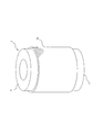
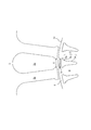
図1、図2は比較のために示す一般的な誘導電動機100を示す図で、図1は回転子1(固定子2も含む)の横断面図、図2はダイキャストなどにより非磁性体且つ導電性(例えば、アルミ、銅等)の材料がスロット内に充填され回転子1端部にエンドリング7が形成された回転子1の斜視図である。
1 and 2 are views showing a
図1は誘導電動機100の横断面図であるが、固定子2は巻線等の図示を省略している。
FIG. 1 is a cross-sectional view of the
固定子2は、全体がリング状で、内周側に複数のスロット2aと、スロット2aの間にティース2bとを形成している。外周側は、磁路となるコアバック2cになっている。固定子2の内側に、回転子1が空隙を介して配置される。
The
回転子1の回転子鉄心1aの構成を説明する。回転子鉄心1aは、外周側に複数のスロット3と、スロット3の間に回転子ティース4を形成している。回転子鉄心1aの中央部に、駆動軸(図示せず)が嵌合する軸孔6が開けられている。スロット3と軸孔6との間の鉄心部分をコアバックと呼ぶ。
The configuration of the rotor core 1a of the
回転子1には、スロット3内にアルミ等が鋳込まれてかご形二次導体が形成される。かご形二次導体は、スロット3内に形成される複数のアルミバーの両端をエンドリング7(図2参照)で短絡する構成である。
In the
図1に示す一般的な回転子1では、周方向に存在する多数のスロット3の間に位置する回転子ティース4の周方向の幅を一定としている。これにより、回転子ティース4の磁束密度が一定となり、バランスのよい設計となる。その場合、スロット3は、周方向の幅が外から内に徐々に小さくなる形状になっている。
In the
しかし、二次抵抗(回転子1のかご形二次導体の抵抗)を低減させて高効率化するため、スロット3の周方向の幅を大きくしてスロット3面積を拡大すると、回転子ティース4の周方向の幅が小さくなる。そのため、回転子ティース4の磁気飽和の影響により、二次抵抗を低減する効果が小さくなってしまう。
However, in order to reduce the secondary resistance (resistance of the cage secondary conductor of the rotor 1) and increase the efficiency, if the circumferential width of the
また、スロット3を二重かご形状として高効率化を図る方法もある。二重かご形状の回転子を有する誘導電動機は一般的な特徴として、起動時はすべり周波数が高くなるため、回転子外周側に磁束が流れ、主として抵抗の高い外層スロットのみに二次電流が流れることで、起動トルクが高くなる。また通常運転時は、すべり周波数が低いので、二次電流は外層スロットと内層スロットの両方に流れるため、二次抵抗が小さくなり、二次銅損が低くなることで、高効率化が実現できるという特性を有している。
There is also a method for improving efficiency by making the
しかし、二重かご形状の回転子は、一般的に外層スロットと内層スロットの間に連結スロットが存在する。そのため、スロットが回転子中心方向に長くなり、風穴や、駆動軸(シャフト)の影響によりスロットを中心方向に長くできない形状では、二重かご形スロットの適用は困難である。 However, a double cage rotor generally has a connection slot between the outer layer slot and the inner layer slot. For this reason, it is difficult to apply the double squirrel-cage slot in a shape in which the slot becomes long in the center direction of the rotor and the slot cannot be lengthened in the center direction due to the influence of the air hole or the drive shaft (shaft).
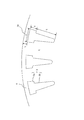
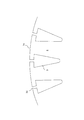
図3乃至図9は実施の形態1を示す図で、図3は回転子鉄心1aのT字形状のスロット3を示す部分拡大平面図、図4は二重かご形状のスロット3を示す部分拡大平面図、図5は回転子鉄心1aの外周部付近(固定子2を含む)の部分拡大平面図、図6は二重かご形状のスロット3を示す部分拡大平面図、図7は変形例の回転子鉄心1aのT字形状のスロット3を示す部分拡大平面図、図8は変形例の二重かご形状のスロット3を示す部分拡大平面図、図9は二重かご形状のスロット3の詳細を示す部分拡大平面図である。
FIGS. 3 to 9 are views showing the first embodiment, FIG. 3 is a partially enlarged plan view showing a T-shaped
図3のスロット3の形状はT字形状である。外層スロット3aと内層スロット3bとで、スロット3を構成する。周方向の幅の広い外層スロット3aが回転子鉄心1aの外周部に位置する。外層スロット3aの内側(回転子鉄心1aの中心側)に周方向の幅の狭い内層スロット3bが位置する(内層スロット3bの周方向の幅は、外層スロット3aの周方向の幅より狭い)。外層スロット3aと内層スロット3bとは直接連結している。
The shape of the
スロット3の形状をT字形状とすることにより、スロット3間の回転子ティース4の周方向の幅が回転子外周部の方が狭い形状となっている。即ち、外層スロット3a間の回転子ティース4の周方向の幅が、内層スロット3b間の回転子ティース4の周方向の幅よりも小さい。尚、外層スロット3a間、内層スロット3b間の各々の回転子ティース4の周方向の幅は、各スロット間の最小ティース幅とする。
By making the shape of the slot 3 T-shaped, the circumferential width of the
このように、図3に示すT字形状のスロット3は、一部の回転子ティース4(外層スロット3a間)の周方向の幅を狭くし、他の回転子ティース4(内層スロット3b間)の周方向の幅を広げることにより、磁気飽和部分を一部の回転子ティース4(外層スロット3a間)の一箇所に集中させ、他の回転子ティース4(内層スロット3b間)の磁気飽和を緩和させることが可能である。
As described above, the T-shaped
回転子ティース4全体が磁気飽和すると、回転子ティース4全体の透磁率が低くなる。しかし、スロット3をT字形状にすることにより、磁気飽和は一部の回転子ティース4(外層スロット3a間)の一箇所に集中するため、透磁率が低い部分が短くなり(径方向に)、結果的にモータ効率が向上する。
When the
また、図4に示すように、スロット3を外層スロット3aと内層スロット3bとを連結スロット3cで連結する二重かご形状とすることも可能である。隣合う連結スロット3cの間の回転子ティース4の周方向の幅は、外層スロット3a間の回転子ティース4の周方向の幅と、内層スロット3b間の回転子ティース4の周方向の幅よりも大きい。尚、隣合う連結スロット3cの間の回転子ティース4の周方向の幅は、隣合う連結スロット3cの間の最大ティース幅とする。
Further, as shown in FIG. 4, the
図3、図4において、スロット3の各部の寸法を次のように定義する。
A:外層スロット3aの半径方向幅
B:内層スロット3bの半径方向幅
C:外層スロット3aの周方向幅
P:連結スロット3cの半径方向幅
L:薄肉部8の半径方向幅3 and 4, the dimensions of each part of the
A: Radial width of the
AとBとの関係を、
A<0.5B (1)
とする。磁気飽和が集中する外層スロット3a間の回転子ティース4の半径方向幅(外層スロット3aの半径方向幅A)が、磁気飽和が緩和される内層スロット3b間の回転子ティース4の半径方向幅(内層スロット3bの半径方向幅B)の1/2以下になる。AをBの1/2以上にすると磁気飽和を集中させる部分が長くなり、逆に効率が悪化してしまう。そのため、AをBの1/2以下とし、磁気飽和を集中させる部分を短くすると、外層スロット3a間の回転子ティース4の磁気飽和のモータ特性への影響が小さくなり、モータ効率が向上する。The relationship between A and B
A <0.5B (1)
And The radial width of the
また、AとCとの関係を、
A<0.5C (2)
とする。外層スロット3aの周方向幅Cが、外層スロット3aの半径方向幅Aの2倍以上になる。即ち、回転子鉄心1aにおける外周部の薄肉部8の周方向の長さが、外層スロット3aの半径方向幅Aの2倍以上になる。そのため、外層スロット3a間の回転子ティース4が磁気飽和しても、CがAの2倍以上であるため、薄肉部8は外層スロット3a間の回転子ティースより十分長く、薄肉部8に磁束が漏れることなく、磁束を有効に使用することができる。Also, the relationship between A and C
A <0.5C (2)
And The circumferential width C of the
薄肉部8は薄肉に構成され、回転子鉄心1aの外周部を漏れる磁束を低減する目的がある。薄肉部8の半径方向幅Lは、加工可能(電磁鋼板の打ち抜き加工が可能)な最小寸法とする。電磁鋼板の打ち抜き加工が可能な最小寸法は、一般的には電磁鋼板の板厚と同程度である。電磁鋼板の板厚は、0.1〜1.5mm程度である。薄肉部8の半径方向幅Lを加工可能な最小寸法で一定にすることにより、漏れ磁束を低減でき、磁束を有効に使用することができる。
The
また、図5において、外層スロット3aの周方向幅Cを、固定子2のスロット2aのスロットオープニング(開口部)の周方向幅Sより大きくする。これにより、漏れ磁束(固定子2の巻線より生成される磁束が回転子1のスロット3と鎖交しない磁束)が小さくなるため有効に磁束を使用することができる。
In FIG. 5, the circumferential width C of the
さらに、薄肉部8の半径方向幅Lが一定である部分がスロットオープニングの周方向幅Sより大きくすることにより、一層有効に磁束を使用することができる。
Furthermore, the magnetic flux can be used more effectively by making the portion where the radial width L of the
また、図4において、外層スロット3aと内層スロット3b間に連結スロット3cを設けることにより、二重かご形状の特性を持たせることができる。しかし、連結スロット3cの半径方向幅Pが大きすぎると、スロット3の半径方向の長さが同一の場合、内層スロット3bの面積が小さくなる。すると、スロット3全体の面積が小さくなり、回転子1の二次抵抗が大きくなる。二次抵抗が大きくなると、モータ効率が低下する。
Further, in FIG. 4, by providing the connecting
従って、連結スロット3cの半径方向幅Pは、可能な限り小さい方がよい。一般的に回転子鉄心1aを構成する電磁鋼板の板厚(0.1〜1.5mm)と同程度が加工可能な最小寸法である。従って、連結スロット3cの半径方向幅Pを、電磁鋼板の板厚と同程度の寸法とする。それにより、回転子1の二次抵抗が大きくならず、二重かご形状の特性を持たせることが可能となる。
Therefore, the radial width P of the connecting
また、図6に示すように、回転子鉄心1aのスロット3をオープンスロットにすることも有効である。スロット3は、外層スロット3aが回転子鉄心1aの外周部に開口部3dを備える。
As shown in FIG. 6, it is also effective to make the
スロット3に開口部3dを設けることにより、漏れ磁束(固定子2の巻線より生成される磁束が回転子1のスロット3と鎖交しない磁束)が小さくなるため有効に磁束を使用することができる。モータ効率が改善される。
By providing the
また、図3、図4、図6に示す外層スロット3aの形状は四角形状である。図7に示すように、例えば外層スロット3aを楕円形状とする。また、図8ではそれに加えて内層スロット3bの外側部分の角部を丸くする。そのように構成することにより、金型の打ち抜き性が向上し、生産性が向上する。さらに、スロット3内に非磁性且つ導電性の材料(アルミや銅など)を充填する際に、外層スロット3aが四角形状では角に充填しにくい。外層スロット3aを楕円形状にすることにより、角がなくなるため充填率が向上する。また、磁気飽和部分もさらに集中する(磁気飽和する回転子ティース4部分の半径方向の長さが短くなる)ため、さらにモータ効率を向上させることができる。
Further, the shape of the
図9に示すように、外層スロット3aの両側側面と回転子鉄心1aの中心とのなす角度をθ1、隣り合う外層スロット3aの近接側の両側面と回転子鉄心1aの中心とのなす角度をθ2とする。本実施の形態では、θ1>θ2となるように構成する。また内層スロット3bは、外層スロット3aのなす角度θ1の内側に収まるように構成されている。
As shown in FIG. 9, the angle formed between both side surfaces of the
このように構成することにより、起動トルク、停動トルク(最大トルク)及び運転効率のバランスが良い誘導電動機100を得ることができる。
By comprising in this way, the
起動トルクを高くするためには、外層スロット3aの断面積を小さくして、二次抵抗を大きくすることが効果的である。しかし、通常運転時の高効率化を行うためには、外層スロット3aと内層スロット3bの両方からなる二次抵抗を低くして、二次銅損を低くする必要がある。
In order to increase the starting torque, it is effective to increase the secondary resistance by reducing the cross-sectional area of the
起動トルクを高くするためにはθ1を小さくして、外層スロット3aの断面積を小さくした方が良い。しかし、外層スロット3aの断面積が小さくなると、通常運転時の二次抵抗が高くなる。内層スロット3bを回転子鉄心1a中心方向に長くすれば、内層スロット3bの断面積を大きくすることは可能である。しかし、中心方向はスロットの幅が細くなるため(回転子ティース4の周方向幅が一定の場合)、所望の断面積を得るためには、内層スロット3bが回転軸に近づいてしまうことがある。内層スロット3bが長くなると言うことは、回転子における磁束密度が高い回転子ティース4の長さが長くなるため、効率が悪化することがある。
In order to increase the starting torque, it is preferable to reduce θ1 and reduce the cross-sectional area of the
また中心方向はスロットの幅が細くなるため、ダイキャストによりアルミを鋳込んだ場合、内層スロット3bの回転子鉄心1a中心側はアルミが流れ込みにくくなり、結果として二次抵抗を低くできず、モータ効率が悪化する可能性もある。
In addition, since the slot width is narrow in the center direction, when aluminum is cast by die casting, aluminum does not easily flow into the rotor core 1a center side of the
別の手段として内層スロット3bの横幅を大きくすることで所望の断面積を得ることができる。しかし、内層スロット3bの横幅が大きくなるということは、通常運転時の磁束の通路である歯幅(回転子ティース4の周方向幅)が細くなることである。歯幅が細くなると磁気抵抗が増加するため、通常運転時のトルクを得るために必要な電流が増加し、モータ効率が悪化する課題がある。
As another means, a desired cross-sectional area can be obtained by increasing the lateral width of the
以上のようにこの実施の形態によれば、以下の効果を奏する。
(1)スロット3をT字形状にすることにより、磁気飽和は一部の回転子ティース4(外層スロット3a間)の一箇所に集中するため、透磁率が低い部分が短くなり、結果的にモータ効率が向上する。
(2)スロット3を外層スロット3aと内層スロット3bとを連結スロット3cで連結する二重かご形状とすることでも、同様の効果を奏する。
(3)外層スロット3aの半径方向幅Aと内層スロット3bの半径方向幅Bとの関係を、A<0.5Bとすることにより、外層スロット3a間の回転子ティース4の磁気飽和のモータ特性への影響が小さくできる。
(4)外層スロット3aの半径方向幅Aと外層スロット3aの周方向幅Cとの関係を、A<0.5Cとすることにより、外層スロット3a間の回転子ティース4が磁気飽和しても、薄肉部8に磁束が漏れることなく、磁束を有効に使用することができる。
(5)薄肉部8の半径方向幅Lを加工可能な最小寸法(電磁鋼板の板厚の0.1〜1.5mm程度)で一定にすることにより、漏れ磁束を低減でき、磁束を有効に使用することができる。
(6)外層スロット3aの周方向幅Cを、固定子2のスロット2aのスロットオープニング(開口部)の周方向幅Sより大きくすることにより、漏れ磁束(固定子2の巻線より生成される磁束が回転子1のスロット3と鎖交しない磁束)が小さくなるため有効に磁束を使用することができる。
(7)さらに、薄肉部8の半径方向幅Lが一定である部分がスロットオープニングの周方向幅Sより大きくすることにより、一層有効に磁束を使用することができる。
(8)連結スロット3cの半径方向幅Pを、電磁鋼板の板厚と同程度の寸法とすることにより、回転子1の二次抵抗が大きくならず、二重かご形状の特性を持たせることが可能となる。(9)スロット3に開口部3dを設けることにより、漏れ磁束(固定子2の巻線より生成される磁束が回転子1のスロット3と鎖交しない磁束)が小さくなるため有効に磁束を使用することができ、モータ効率が改善される。
(10)図7のスロット3では、外層スロット3aを楕円形状とする。また、図8のスロット3ではそれに加えて内層スロット3bの外側部分の角部を丸くすることにより、金型の打ち抜き性が向上し、生産性が向上する。さらに、スロット3内に非磁性且つ導電性の材料を充填する際に、角がなくなるため充填率が向上する。また、磁気飽和部分もさらに集中するため、さらにモータ効率を向上させることができる。
(11)外層スロット3aの両側側面と回転子鉄心1aの中心とのなす角度θ1と、隣り合う外層スロット3aの近接側の両側面と回転子鉄心1aの中心とのなす角度θ2との関係を、θ1>θ2となるように構成することにより、起動トルク、停動トルク(最大トルク)及び運転効率のバランスが良い誘導電動機100を得ることができる。As described above, according to this embodiment, the following effects can be obtained.
(1) By making the slot 3 T-shaped, the magnetic saturation is concentrated in one part of the rotor teeth 4 (between the
(2) The same effect can be obtained by forming the
(3) By setting the relationship between the radial width A of the
(4) By setting the relationship between the radial width A of the
(5) By making the radial width L of the thin-
(6) By making the circumferential width C of the
(7) Furthermore, the magnetic flux can be used more effectively by making the portion where the radial width L of the
(8) By making the radial width P of the
(10) In the
(11) The relationship between the angle θ1 formed between both side surfaces of the
実施の形態2.
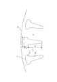
図10乃至図13は実施の形態2を示す図で、図10は回転子鉄心1aの外層スロット、中層スロット及び内層スロットを備えるスロット3を示す部分拡大平面図、図11は回転子鉄心1aの外周部付近(固定子2を含む)の部分拡大平面図、図12は変形例の回転子鉄心1aの外層スロット、中層スロット及び内層スロットを備えるスロット3を示す部分拡大平面図、図13は別の変形例の回転子鉄心1aの外層スロット、中層スロット及び内層スロットを備えるスロット3を示す部分拡大平面図である。
FIGS. 10 to 13 are views showing the second embodiment. FIG. 10 is a partially enlarged plan view showing a
図10に示す回転子鉄心1aのスロット3は、外層スロット3a、中層スロット3e及び内層スロット3bを備える。各層のスロットが連通している。そして、外層スロット3aの周方向の幅、中層スロット3eの周方向の幅、内層スロット3bの周方向の幅の関係を、外層スロット3aの周方向の幅>中層スロット3eの周方向の幅>内層スロット3bの周方向の幅とする。さらに、外層スロット3a間の回転子ティース4の周方向の幅<隣合う中層スロット3e間の回転子ティース4の周方向の幅<隣合う内層スロット3b間の回転子ティース4の周方向の幅とする。尚、外層スロット3a間、中層スロット3e間、内層スロット3b間の各々の回転子ティース4の周方向の幅は、各スロット間の最小ティース幅とする。
The
従って、回転子ティース4幅は、回転子鉄心1aの内周部よりも回転子鉄心1aの外周部の方が狭い形状となっている。
Therefore, the width of the
実施の形態1で説明したように、一部分の回転子ティース4の周方向幅を狭くし、他の回転子ティース4部分の周方向幅を広げることにより、磁気飽和部分を一箇所に集中させ、他の回転子ティース4部分の磁気飽和を緩和させる。それにより、回転子ティース4全体が磁気飽和せず、一部分の回転子ティース4に磁気飽和が集中するため、透磁率が低い部分が短くなり、結果的にモータ効率が向上する。回転子ティース4幅を、図10に示すように三段形状とすることにより、さらに磁気飽和は分散され、よりモータ効率を向上させることが可能である。
As described in the first embodiment, by narrowing the circumferential width of a part of the
図10に示すスロットの各部の寸法を次のように定義する。
G:外層スロット3aの半径方向幅
H:中層スロット3eの半径方向幅
I:内層スロット3bの半径方向幅
D:外層スロット3aの周方向幅、
L:外層スロット3aと回転子鉄心1aの外周部との間隔The dimensions of each part of the slot shown in FIG. 10 are defined as follows.
G: radial width of
L: Distance between
G、H、Iの関係を、
G+H<0.5I (3)
とする。磁気飽和が集中する外層スロット3aの間の回転子ティース4の半径方向の幅(外層スロット3aの半径方向幅G)及び中層スロット3eの間の回転子ティース4の半径方向の幅(中層スロット3eの半径方向幅H)が、磁気飽和が緩和される内層スロット3bの間の回転子ティース4の半径方向の幅(内層スロット3bの半径方向幅I)の1/2以下となる。そのため、実施の形態1で示したように外層スロット3a間の回転子ティース4及び中層スロット3eの間の回転子ティース4の磁気飽和のモータ特性への影響が小さくなる。The relationship between G, H, and I
G + H <0.5I (3)
And The radial width of the
また、G+HとDとの関係を、
G+H<0.5D (4)
とする。外層スロット3aの周方向幅Dが、外層スロット3aの半径方向幅Gと中層スロット3e半径方向幅Hとの和の2倍以上になる。即ち、回転子鉄心1aにおける外周部の薄肉部8の周方向の長さが、外層スロット3aの半径方向幅Gと中層スロット3e半径方向幅Hとの和の2倍以上になる。そのため、実施の形態1で示したように外層スロット3a及び中層スロット3e間の回転子ティース4が磁気飽和しても、薄肉部8に磁束が漏れることなく、磁束を有効に使用することができる。Also, the relationship between G + H and D is
G + H <0.5D (4)
And The circumferential width D of the
実施の形態1と同様、薄肉部8は薄肉に構成され、回転子鉄心1aの外周部を漏れる磁束を低減する目的がある。薄肉部8の半径方向幅Lは、加工可能(電磁鋼板の打ち抜き加工が可能)な最小寸法とする。電磁鋼板の打ち抜き加工が可能な最小寸法は、一般的には電磁鋼板の板厚と同程度である。電磁鋼板の板厚は、0.1〜1.5mm程度である。薄肉部8の半径方向幅Lを加工可能な最小寸法で一定にすることにより、漏れ磁束を低減でき、磁束を有効に使用することができる。
Similar to the first embodiment, the
また、図11において、外層スロット3aの周方向幅Dを、固定子2のスロット2aのスロットオープニング(開口部)の周方向幅Sより大きくする。これにより、漏れ磁束(固定子2の巻線より生成される磁束が回転子1のスロット3と鎖交しない磁束)が小さくなるため有効に磁束を使用することができる。
In FIG. 11, the circumferential width D of the
さらに、薄肉部8の半径方向幅Lが一定である部分がスロットオープニングの周方向幅Sより大きくすることにより、一層有効に磁束を使用することができる。
Furthermore, the magnetic flux can be used more effectively by making the portion where the radial width L of the
また、図12に示すように、回転子鉄心1aのスロット3をオープンスロットにすることも有効である。スロット3は、外層スロット3aが回転子鉄心1aの外周部に開口部3dを備える。
As shown in FIG. 12, it is also effective to make the
スロット3に開口部3dを設けることにより、漏れ磁束(固定子2の巻線より生成される磁束が回転子1のスロット3と鎖交しない磁束)が小さくなるため有効に磁束を使用することができる。モータ効率が改善される。
By providing the
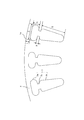
また、図10乃至図12に示す外層スロット3a、中層スロット3eの形状は四角形状であるが、図13に示すように、外層スロット3a、中層スロット3eを楕円形状とする。そのように構成することにより、金型の打ち抜き性が向上し、生産性が向上する。さらに、スロット3内に非磁性且つ導電性の材料(アルミや銅など)を充填する際に、外層スロット3a、中層スロット3eが四角形状では角に充填しにくい。外層スロット3a、中層スロット3eを楕円形状にすることにより、角がなくなるため充填率が向上する。また、磁気飽和部分もさらに集中する(磁気飽和する回転子ティース4部分の半径方向の長さが短くなる)ため、さらにモータ効率を向上させることができる。
Further, the
以上のようにこの実施の形態によれば、以下の効果を奏する。
(1)スロット3を、各層が連通している外層スロット3a、中層スロット3e及び内層スロット3bを備え、外層スロット3aの周方向の幅>中層スロット3eの周方向の幅>内層スロット3bの周方向の幅とし、さらに外層スロット3a間の回転子ティース4の周方向の幅<隣合う中層スロット3e間の回転子ティース4の周方向の幅<隣合う内層スロット3b間の回転子ティース4の周方向の幅とすることにより、磁気飽和は一部の回転子ティース4(外層スロット3a間及び中層スロット3e間)の一箇所に集中するため、透磁率が低い部分が短くなり、結果的にモータ効率が向上する。
(2)外層スロット3aの半径方向幅Gと中層スロット3eの半径方向幅Hとの和と、内層スロット3bの半径方向幅Iとの関係を、G+H<0.5Iとすることにより、外層スロット3a間の回転子ティース4及び中層スロット3eの間の回転子ティース4の磁気飽和のモータ特性への影響が小さくできる。
(3)外層スロット3aの半径方向幅Gと中層スロット3e半径方向幅Hとの和と、外層スロット3aの周方向幅Dとの関係を、G+H<0.5Dとすることにより、外層スロット3a及び中層スロット3e間の回転子ティース4が磁気飽和しても、薄肉部8に磁束が漏れることなく、磁束を有効に使用することができる。
(4)薄肉部8の半径方向幅Lを加工可能な最小寸法(電磁鋼板の板厚の0.1〜1.5mm程度)で一定にすることにより、漏れ磁束を低減でき、磁束を有効に使用することができる。
(5)外層スロット3aの周方向幅Dを、固定子2のスロット2aのスロットオープニング(開口部)の周方向幅Sより大きくすることにより、漏れ磁束(固定子2の巻線より生成される磁束が回転子1のスロット3と鎖交しない磁束)が小さくなるため有効に磁束を使用することができる。
(6)さらに、薄肉部8の半径方向幅Lが一定である部分がスロットオープニングの周方向幅Sより大きくすることにより、一層有効に磁束を使用することができる。
(7)スロット3に開口部3dを設けることにより、漏れ磁束(固定子2の巻線より生成される磁束が回転子1のスロット3と鎖交しない磁束)が小さくなるため有効に磁束を使用することができ、モータ効率が改善される。
(8)外層スロット3a、中層スロット3eを楕円形状とすることにより、金型の打ち抜き性が向上し、生産性が向上する。さらに、スロット3内に非磁性且つ導電性の材料を充填する際に、角がなくなるため充填率が向上する。また、磁気飽和部分もさらに集中するため、さらにモータ効率を向上させることができる。As described above, according to this embodiment, the following effects can be obtained.
(1) The
(2) By setting the relationship between the sum of the radial width G of the
(3) By setting the relationship between the sum of the radial width G of the
(4) By making the radial width L of the thin-
(5) By making the circumferential width D of the
(6) Furthermore, the magnetic flux can be used more effectively by making the portion where the radial width L of the
(7) By providing the
(8) By making the
実施の形態3.
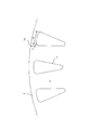
図14乃至図17は実施の形態3を示す図で、図14は回転子鉄心1aの隣り合うスロット3の間の回転子ティース4の幅が回転子鉄心1a中心に向かうにつれ広くなる略三角形状のスロット3を示す部分拡大平面図、図15は回転子鉄心1aの外周部付近(固定子2を含む)の部分拡大平面図、図16は変形例の回転子鉄心1aの隣り合うスロット3の間の回転子ティース4の幅が回転子鉄心1a中心に向かうにつれ広くなる略三角形状のスロット3を示す部分拡大平面図、図17は別の変形例の回転子鉄心1aの隣り合うスロット3の間の回転子ティース4の幅が回転子鉄心1a中心に向かうにつれ広くなる略三角形状のスロット3を示す部分拡大平面図である。
FIGS. 14 to 17 show the third embodiment. FIG. 14 shows a substantially triangular shape in which the width of the
図14に示すスロット3は、隣り合うスロット3の間の回転子ティース4の周方向の幅が、回転子鉄心1a中心に向かうにつれ広くなる略三角形状のスロット3である。即ち、外周側の回転子ティース4の周方向の幅J1は、中心側の回転子ティース4の周方向の幅J2よりも小さい。
The
そしてスロット3と回転子鉄心1aの外周部との間の薄肉部8の寸法Lを一定とした構成である。
And the dimension L of the
実施の形態1で説明したように、一部分の回転子ティース4の周方向幅を狭くし、他の回転子ティース4部分の周方向幅を広げることにより、磁気飽和部分を一箇所に集中させ、他の回転子ティース4部分の磁気飽和を緩和させる。それにより、回転子ティース4全体が磁気飽和せず、一部分の回転子ティース4に磁気飽和が集中するため、透磁率が低い部分が短くなり、結果的にモータ効率が向上する。図14に示すように、回転子ティース4の周方向幅を回転子鉄心1aの中心に向って徐々に広くすることにより、回転子ティース4の磁束密度が回転子鉄心1aの中心になるほど低くなり、磁気飽和が分散され、よりモータ効率を向上させることが可能である。
As described in the first embodiment, by narrowing the circumferential width of a part of the
さらに、回転子ティース4と回転子鉄心1aの外周部の薄肉部8の半径方向幅Lを一定とすることにより、回転子鉄心1aの外周部からの漏れ磁束が少なくなり、高効率な運転が可能である。
Furthermore, by making the radial width L of the
また、図15において、スロット3の外側の周方向幅Kを固定子2のスロット2aのスロットオープニング(開口部)の周方向幅Sより大きくする。これにより、漏れ磁束(固定子2の巻線より生成される磁束が回転子1のスロット3と鎖交しない磁束)が小さくなるため有効に磁束を使用することができる。
In FIG. 15, the circumferential width K outside the
さらに、薄肉部8の半径方向幅Lが一定である部分が固定子2のスロットオープニングの周方向幅Sより大きくすることにより、一層有効に磁束を使用することができる。
Furthermore, by making the portion where the radial width L of the
また、図16に示すように、回転子鉄心1aのスロット3をオープンスロットにすることも有効である。スロット3は、回転子鉄心1aの外周部に開口部3dを備える。
As shown in FIG. 16, it is also effective to make the
スロット3に開口部3dを設けることにより、漏れ磁束(固定子2の巻線より生成される磁束が回転子1のスロット3と鎖交しない磁束)が小さくなるため有効に磁束を使用することができる。モータ効率が改善される。
By providing the
また、図14乃至図16に示すスロット3の回転子鉄心1aの外周部側の形状を、図17に示すように、鋭角の両角部に丸みを持たせることにより、金型の打ち抜き性が向上し、生産性が向上する。さらに、スロット3内に非磁性且つ導電性の材料(アルミや銅など)を充填する際に、スロット3が鋭角の両角部を持つ形状では角に充填しにくい。鋭角の両角部に丸みを持たせることにより、角がなくなるため充填率が向上する。
Further, the shape of the outer peripheral portion of the rotor core 1a of the
以上のようにこの実施の形態によれば、以下の効果を奏する。
(1)スロット3を、隣り合うスロット3の間の回転子ティース4の幅が、回転子鉄心1a中心に向かうにつれ広くなる略三角形状にすることにより、回転子ティース4の周方向幅が回転子鉄心1aの中心に向って徐々に広くなる。よって、回転子ティース4の磁束密度が回転子鉄心1aの中心になるほど低くなり、磁気飽和が分散され、よりモータ効率を向上させることが可能である。
(2)回転子ティース4と回転子鉄心1aの外周部の薄肉部8の半径方向幅Lを一定とすることにより、回転子鉄心1aの外周部からの漏れ磁束が少なくなり、高効率な運転が可能である。
(3)スロット3の外側の周方向幅Kを固定子2のスロット2aのスロットオープニング(開口部)の周方向幅Sより大きくすることにより、漏れ磁束(固定子2の巻線より生成される磁束が回転子1のスロット3と鎖交しない磁束)が小さくなるため有効に磁束を使用することができる。
(4)薄肉部8の半径方向幅Lが一定である部分が固定子2のスロットオープニングの周方向幅Sより大きくすることにより、一層有効に磁束を使用することができる。
(5)スロット3に開口部3dを設けることにより、漏れ磁束(固定子2の巻線より生成される磁束が回転子1のスロット3と鎖交しない磁束)が小さくなるため有効に磁束を使用することができる。モータ効率が改善される。
(6)スロット3の回転子鉄心1aの外周部側の鋭角の両角部に丸みを持たせることにより、金型の打ち抜き性が向上し、生産性が向上する。さらに、スロット3内に非磁性且つ導電性の材料を充填する際に、角がなくなるため充填率が向上する。また、磁気飽和部分もさらに集中するため、さらにモータ効率を向上させることができる。As described above, according to this embodiment, the following effects can be obtained.
(1) The circumferential width of the
(2) By making the radial width L of the
(3) By making the circumferential width K outside the
(4) By making the portion where the radial width L of the
(5) Since the
(6) By rounding both the acute angle corners on the outer peripheral side of the rotor core 1a of the
実施の形態4.
単相の電源により駆動される一定速の単相誘導電動機は、起動トルクが三相誘導電動機に比べ小さく、起動トルク向上の要求が高い。一定速の誘導電動機は起動時の電流が、定格電流に比べ大きく、回転子ティース4が磁気飽和している状態で使用している。実施の形態1乃至3にて示した回転子1のスロット3形状により、磁気飽和を回転子鉄心1aの外周部に集中させ、内側(回転子鉄心1aの中心側)の回転子ティース4の磁気飽和が緩和し、起動トルク向上が可能であるため、単相誘導電動機には有効な回転子1のスロット3形状である。
A constant-speed single-phase induction motor driven by a single-phase power source has a smaller starting torque than a three-phase induction motor, and there is a high demand for improving the starting torque. The constant-speed induction motor is used in a state where the current at startup is larger than the rated current and the
また、実施の形態1乃至3のいずれかの回転子1を用いる誘導電動機を、圧縮機、送風機等に用いることにより、圧縮機、送風機等を高効率化することが可能である。また、これらの圧縮機、送風機等を搭載した空気調和機も高効率化することが可能である。
Further, by using the induction motor that uses the
1 回転子、1a 回転子鉄心、2 固定子、2a スロット、2b ティース、2c コアバック、3 スロット、3a 外層スロット、3b 内層スロット、3c 連結スロット、3d 開口部、3e 中層スロット、4 回転子ティース、6 軸孔、7 エンドリング、8 薄肉部、100 誘導電動機。 1 rotor, 1a rotor core, 2 stator, 2a slot, 2b teeth, 2c core back, 3 slot, 3a outer layer slot, 3b inner layer slot, 3c connection slot, 3d opening, 3e middle layer slot, 4 rotor teeth , 6 shaft hole, 7 end ring, 8 thin part, 100 induction motor.
Claims (18)
前記スロットは略T字形状であり、該スロットを前記回転子鉄心の外周部に位置する外層スロットと、前記外層スロットの内側に位置する内層スロットとで構成し、
前記スロットは、前記外層スロットの周方向の幅を、前記内層スロットの周方向の幅よりも広くし、
前記スロットは、隣合う前記外層スロット間の回転子ティースの周方向幅を、隣合う前記内層スロット間の前記回転子ティースの周方向幅より狭くなるようにしたことを特徴とする誘導電動機の回転子。In the rotor of an induction motor having a squirrel-cage secondary conductor formed by filling a nonmagnetic and conductive material in a slot of a rotor core,
The slot is substantially T-shaped, and the slot is composed of an outer layer slot located on the outer periphery of the rotor core and an inner layer slot located inside the outer layer slot;
The slot has a circumferential width of the outer layer slot wider than a circumferential width of the inner layer slot,
The induction motor according to claim 1, wherein the slot is configured such that a circumferential width of the rotor teeth between the adjacent outer layer slots is narrower than a circumferential width of the rotor teeth between the adjacent inner layer slots. Child.
前記スロットは略T字形状であり、該スロットを前記回転子鉄心の外周部に位置する外層スロットと、前記外層スロットの内側に位置する内層スロットとで構成し、
前記スロットは、前記外層スロットの周方向の幅を、前記内層スロットの周方向の幅よりも広くし、
前記スロットは、隣合う前記外層スロット間の回転子ティースの周方向の幅を、隣合う前記内層スロット間の前記回転子ティースの周方向の幅より狭くなるようにし、
前記スロットは、前記外層スロットと前記内層スロットとの間に連結スロットを有し、
前記スロットは、隣合う前記連結スロットの間の前記回転子ティースの周方向の幅を、隣合う前記外層スロット間の前記回転子ティースの周方向の幅と、隣合う前記内層スロット間の前記回転子ティースの周方向の幅よりも大きくしたことを特徴とする誘導電動機の回転子。In the rotor of an induction motor having a squirrel-cage secondary conductor formed by filling a nonmagnetic and conductive material in a slot of a rotor core,
The slot is substantially T-shaped, and the slot is composed of an outer layer slot located on the outer periphery of the rotor core and an inner layer slot located inside the outer layer slot;
The slot has a circumferential width of the outer layer slot wider than a circumferential width of the inner layer slot,
The slot is configured such that the circumferential width of the rotor teeth between the adjacent outer layer slots is narrower than the circumferential width of the rotor teeth between the adjacent inner layer slots,
The slot has a connection slot between the outer layer slot and the inner layer slot;
The slot has a circumferential width of the rotor teeth between adjacent connecting slots, a circumferential width of the rotor teeth between adjacent outer layer slots, and the rotation between adjacent inner layer slots. An induction motor rotor characterized in that it is larger than the circumferential width of the child teeth.
A<0.5B
の関係を満たすことを特徴とする請求項1記載の誘導電動機の回転子。A radial width of the outer layer slot is defined as A, a radial width of the inner layer slot is defined as B, and A and B are:
A <0.5B
The rotor of the induction motor according to claim 1, wherein the relationship is satisfied.
A<0.5B
の関係を満たすことを特徴とする請求項2記載の誘導電動機の回転子。A radial width of the outer layer slot is defined as A, a radial width of the inner layer slot is defined as B, and A and B are:
A <0.5B
The rotor of the induction motor according to claim 2, wherein the relationship is satisfied.
A<0.5C
の関係を満たすことを特徴とする請求項1記載の誘導電動機の回転子。The radial width of the outer layer slot is defined as A, the circumferential width of the outer layer slot is defined as C, and A and C are:
A <0.5C
The rotor of the induction motor according to claim 1, wherein the relationship is satisfied.
A<0.5C
の関係を満たすことを特徴とする請求項2記載の誘導電動機の回転子。The radial width of the outer layer slot is defined as A, the circumferential width of the outer layer slot is defined as C, and A and C are:
A <0.5C
The rotor of the induction motor according to claim 2, wherein the relationship is satisfied.
前記スロットは、夫々が連通した外層スロットと、中層スロットと、内層スロットとを備え、前記外層スロットの周方向の幅、前記中層スロットの周方向の幅、前記内層スロットの周方向の幅の関係を、
外層スロットの周方向の幅>中層スロットの周方向の幅>内層スロットの周方向の幅とし、
さらに隣合う前記外層スロット間の前記回転子ティースの周方向の幅、隣合う前記中層スロット間の前記回転子ティースの周方向の幅、隣合う前記内層スロット間の前記回転子ティースの周方向の幅の関係を、
外層スロット間の回転子ティースの周方向の幅<隣合う中層スロット間の回転子ティースの周方向の幅<隣合う内層スロット間の回転子ティースの周方向の幅
とすることを特徴とする誘導電動機の回転子。In the rotor of an induction motor having a squirrel-cage secondary conductor formed by filling a nonmagnetic and conductive material in a slot of a rotor core,
The slot includes an outer layer slot, an intermediate layer slot, and an inner layer slot that communicate with each other, and a relationship between a circumferential width of the outer layer slot, a circumferential width of the middle layer slot, and a circumferential width of the inner layer slot The
Outer layer slot circumferential width> Middle layer slot circumferential width> Inner layer slot circumferential width,
Further, the circumferential width of the rotor teeth between the adjacent outer layer slots, the circumferential width of the rotor teeth between the adjacent middle layer slots, and the circumferential width of the rotor teeth between the adjacent inner layer slots. Width relationship,
The circumferential width of the rotor teeth between the outer layer slots <the circumferential width of the rotor teeth between the adjacent middle layer slots <the circumferential width of the rotor teeth between the adjacent inner layer slots. Electric motor rotor.
G+H<0.5I
の関係を満たすことを特徴とする請求項8記載の誘導電動機の回転子。The radial width of the outer layer slot is defined as G, the radial width of the middle layer slot is defined as H, and the radial width of the inner layer slot is defined as I. G, H, I are
G + H <0.5I
The rotor of the induction motor according to claim 8, wherein the relationship is satisfied.
Applications Claiming Priority (3)
| Application Number | Priority Date | Filing Date | Title |
|---|---|---|---|
| JP2007335776 | 2007-12-27 | ||
| JP2007335776 | 2007-12-27 | ||
| PCT/JP2008/059127 WO2009084251A1 (en) | 2007-12-27 | 2008-05-19 | Rotator for induction electric motor, induction electric motor, compressor, blower, and air-conditioning device |
Publications (2)
| Publication Number | Publication Date |
|---|---|
| JP4672083B2 true JP4672083B2 (en) | 2011-04-20 |
| JPWO2009084251A1 JPWO2009084251A1 (en) | 2011-05-12 |
Family
ID=40823986
Family Applications (1)
| Application Number | Title | Priority Date | Filing Date |
|---|---|---|---|
| JP2009547920A Active JP4672083B2 (en) | 2007-12-27 | 2008-05-19 | Induction motor rotor, induction motor, compressor, blower and air conditioner |
Country Status (8)
| Country | Link |
|---|---|
| US (2) | US8466597B2 (en) |
| EP (2) | EP2200160B1 (en) |
| JP (1) | JP4672083B2 (en) |
| KR (1) | KR101102146B1 (en) |
| CN (1) | CN101842967B (en) |
| MY (2) | MY177440A (en) |
| TW (1) | TW200929800A (en) |
| WO (1) | WO2009084251A1 (en) |
Cited By (1)
| Publication number | Priority date | Publication date | Assignee | Title |
|---|---|---|---|---|
| US9287759B2 (en) | 2010-12-06 | 2016-03-15 | Mitsubishi Electric Corporation | Induction motor, compressor, air blower, and air conditioner |
Families Citing this family (40)
| Publication number | Priority date | Publication date | Assignee | Title |
|---|---|---|---|---|
| EP2200160B1 (en) * | 2007-12-27 | 2019-06-26 | Mitsubishi Electric Corporation | Rotator for induction electric motor, induction electric motor, compressor, blower, and air-conditioning device |
| MY154195A (en) * | 2008-01-25 | 2015-05-15 | Mitsubishi Electric Corp | Induction motor and hermetic compressor |
| MY156192A (en) * | 2008-08-05 | 2016-01-29 | Mitsubishi Electric Corp | Induction motor and hermetic compressor |
| EP2388891A1 (en) * | 2010-05-19 | 2011-11-23 | Siemens Aktiengesellschaft | Generator with compact single turn wave winding and wind turbine |
| DE102010021470A1 (en) * | 2010-05-25 | 2011-12-01 | Siemens Aktiengesellschaft | Squirrel cage rotor for an asynchronous machine and method of manufacturing the squirrel cage rotor |
| CN103181066B (en) * | 2010-10-19 | 2016-10-12 | 三菱电机株式会社 | The rotor of induction conductivity, induction conductivity, compressor, pressure fan and air-conditioning |
| JP5591099B2 (en) | 2010-12-28 | 2014-09-17 | 三菱電機株式会社 | Compressor and refrigeration cycle equipment |
| CN102655353A (en) * | 2011-03-01 | 2012-09-05 | 中山大洋电机制造有限公司 | External tooth type stator iron core |
| JP5084980B1 (en) * | 2012-04-06 | 2012-11-28 | 三菱電機株式会社 | Double cage rotor |
| JP2013051881A (en) * | 2012-12-12 | 2013-03-14 | Mitsubishi Electric Corp | Induction motor, compressor, and refrigeration cycle device |
| CN103912243B (en) * | 2013-01-07 | 2017-12-15 | 陈雪 | The soft transmission beam-pumping unit of invariable power |
| US10396615B2 (en) | 2013-02-28 | 2019-08-27 | General Electric Company | Electric machine stator lamination with dual phase magnetic material |
| US9520751B2 (en) * | 2013-07-24 | 2016-12-13 | General Electric Company | System and method for smoothing a salient rotor in electrical machines |
| US9653954B2 (en) * | 2013-09-18 | 2017-05-16 | Siemens Industry, Inc. | Electric machine rotor with rotor vent and axial slot fluid communication |
| KR102080634B1 (en) * | 2013-10-15 | 2020-02-24 | 현대모비스 주식회사 | Rotor with 2-step shaped slot and Induction motor having the same |
| JP2015186274A (en) * | 2014-03-20 | 2015-10-22 | 株式会社豊田中央研究所 | Rotor of rotary electric machine and rotary electric machine including the same |
| CN104135095A (en) * | 2014-07-23 | 2014-11-05 | 珠海凌达压缩机有限公司 | Motor rotor |
| WO2016080284A1 (en) * | 2014-11-21 | 2016-05-26 | 株式会社東芝 | Induction motor |
| DE112016002076T5 (en) * | 2015-05-07 | 2018-01-25 | Mitsubishi Electric Corporation | ROTATING ELECTRICAL MACHINE AND METHOD FOR THE PRODUCTION THEREOF |
| CN105119406B (en) * | 2015-08-28 | 2018-06-05 | 郑州凌达压缩机有限公司 | Double-cage rotor punching, double-cage rotor and motor |
| DE112016006435T5 (en) * | 2016-02-15 | 2018-10-31 | Mitsubishi Electric Corporation | Three-phase induction motor and secondary conductor for it |
| US10498280B1 (en) | 2016-08-25 | 2019-12-03 | Apple Inc. | Electric motor with shielded phase windings |
| CN108123560B (en) * | 2016-11-30 | 2021-10-26 | 亨特风扇公司 | Stator of motor for ceiling fan |
| DE102016124830A1 (en) * | 2016-12-19 | 2018-06-21 | Fraunhofer-Gesellschaft zur Förderung der angewandten Forschung e.V. | Sheet for forming a laminated core for a rotor of an electrical machine |
| JP6914742B2 (en) * | 2017-06-16 | 2021-08-04 | 株式会社東芝 | Induction motor rotor |
| FR3069725B1 (en) | 2017-07-31 | 2021-01-29 | Leroy Somer Moteurs | INJECTED CAGE ROTOR |
| US11735969B2 (en) * | 2017-07-31 | 2023-08-22 | William R. Benner, Jr. | High torque low inertia brushless motor |
| FR3069726B1 (en) * | 2017-07-31 | 2020-12-11 | Leroy Somer Moteurs | INJECTED CAGE ROTOR |
| US10804781B2 (en) | 2017-12-30 | 2020-10-13 | Abb Schweiz Ag | Electrical machines and methods for manufacturing electrical machines |
| WO2019244240A1 (en) * | 2018-06-19 | 2019-12-26 | 三菱電機株式会社 | Rotor and rotary electric machine |
| EP3618232A1 (en) * | 2018-08-30 | 2020-03-04 | Siemens Aktiengesellschaft | Electric machine, method for producing an electric machine and electric vehicle |
| FR3090234B1 (en) | 2018-12-14 | 2021-11-12 | Ge Energy Power Conversion Technology Ltd | Blind shaft rotor and associated rotating electrical machine |
| CN111384790A (en) * | 2018-12-28 | 2020-07-07 | 福特全球技术公司 | Stator for motor and motor |
| CN110247491A (en) * | 2019-06-21 | 2019-09-17 | 卧龙电气驱动集团股份有限公司 | A kind of motor rotor punching sheet of three slot continuous structure of deep slot type |
| CN112311112B (en) * | 2020-09-14 | 2021-09-07 | 珠海格力电器股份有限公司 | Rotor punching sheet, rotor core, motor rotor, motor and compressor |
| JP2022055707A (en) * | 2020-09-29 | 2022-04-08 | 本田技研工業株式会社 | Rotary electric machine |
| US11661646B2 (en) | 2021-04-21 | 2023-05-30 | General Electric Comapny | Dual phase magnetic material component and method of its formation |
| US11926880B2 (en) | 2021-04-21 | 2024-03-12 | General Electric Company | Fabrication method for a component having magnetic and non-magnetic dual phases |
| FR3131990A1 (en) * | 2022-01-19 | 2023-07-21 | Safran Ventilation Systems | Rotating electrical machine rotor comprising conductors of free section |
| WO2024024071A1 (en) * | 2022-07-29 | 2024-02-01 | 株式会社日立インダストリアルプロダクツ | Rotary electric machine and slit-forming method for rotor slot |
Citations (8)
| Publication number | Priority date | Publication date | Assignee | Title |
|---|---|---|---|---|
| JPS54148207A (en) * | 1978-05-12 | 1979-11-20 | Toshiba Corp | Cast rotor for rotary electric machine |
| JPS563559A (en) * | 1979-06-22 | 1981-01-14 | Toshiba Corp | Manufacturing of cage rotor |
| JPH027771A (en) * | 1988-06-27 | 1990-01-11 | Toshiba Corp | Facsimile equipment |
| JPH03285542A (en) * | 1990-03-30 | 1991-12-16 | Toshiba Corp | Squirrel-cage rotor |
| JPH07163107A (en) * | 1993-12-06 | 1995-06-23 | Mitsubishi Electric Corp | Squirrel-cage induction motor, manufacture thereof, and fluid machinery having square torque characteristics driven thereby |
| JPH09224358A (en) * | 1996-02-16 | 1997-08-26 | Hitachi Ltd | Induction motor |
| JPH10322939A (en) * | 1997-05-15 | 1998-12-04 | Hitachi Ltd | Dynamoelectric machine and iron core thereof |
| JP2004056860A (en) * | 2002-07-17 | 2004-02-19 | Fujitsu General Ltd | Induction motor |
Family Cites Families (66)
| Publication number | Priority date | Publication date | Assignee | Title |
|---|---|---|---|---|
| US980986A (en) | 1906-08-22 | 1911-01-10 | Gen Electric | Alternating-current electric motor. |
| FR564927A (en) * | 1923-01-20 | 1924-01-15 | Acec | Improvements to short-circuited rotors for asynchronous motors |
| US1650795A (en) | 1924-12-16 | 1927-11-29 | Us Electrical Mfg Company | Bimetallic rotor for induction motors |
| US1708909A (en) | 1925-12-17 | 1929-04-09 | Crockerwheeler Electric Mfg Co | Rotor for induction motors |
| US1650895A (en) * | 1926-11-24 | 1927-11-29 | Bates Valve Bag Co | Bag-valving apparatus |
| US1771936A (en) | 1927-10-11 | 1930-07-29 | Gen Electric | Induction motor |
| US1957551A (en) | 1930-04-17 | 1934-05-08 | Electric Specialty Co | Electric motor |
| US2139748A (en) | 1936-11-18 | 1938-12-13 | Reliance Electric & Eng Co | Squirrel cage rotor and process for making the same |
| US2292167A (en) * | 1940-07-20 | 1942-08-04 | Allis Louis Co | Induction motor |
| US2370458A (en) * | 1942-09-14 | 1945-02-27 | Allis Louis Co | Cast squirrel cage rotor |
| US3401291A (en) * | 1966-01-26 | 1968-09-10 | Gen Electric | Bar design for high torque, low slip squirrel cage rotors |
| DE1563345A1 (en) * | 1966-06-07 | 1970-03-26 | Siemens Ag | Exchange bar runner for asynchronous machines |
| FR1568986A (en) * | 1967-03-18 | 1969-05-30 | ||
| JPS4729503U (en) | 1971-04-30 | 1972-12-04 | ||
| JPS5171915A (en) | 1974-12-19 | 1976-06-22 | Tokyo Shibaura Electric Co | KAITENDENKI |
| JPS5239106A (en) | 1975-09-25 | 1977-03-26 | Hitachi Ltd | Cage rotor of induction motor |
| JPS6023584B2 (en) | 1977-12-14 | 1985-06-08 | 株式会社日立製作所 | Permanent magnet synchronous motor |
| CS215749B1 (en) * | 1980-12-16 | 1982-09-15 | Eduard Krumpolc | Asynchronous motor for feeding from non-sinusoidal voltage and/or current sources |
| JPS58176540U (en) | 1982-05-20 | 1983-11-25 | 三菱電機株式会社 | rotor of rotating electric machine |
| JPS5910159A (en) | 1982-07-07 | 1984-01-19 | Hitachi Ltd | Manufacture of core for die cast rotor |
| JPS60162434A (en) | 1984-02-01 | 1985-08-24 | Ebara Corp | Liquid-cooled rotary electric machine |
| JPS61244248A (en) | 1985-04-22 | 1986-10-30 | Toshiba Corp | Preparation of cast rotor |
| JPS6268468U (en) | 1985-10-14 | 1987-04-28 | ||
| JPS62189929A (en) | 1986-02-13 | 1987-08-19 | Mitsubishi Electric Corp | Rotor for rotary electric machine and its manufacture |
| US4782260A (en) * | 1987-02-27 | 1988-11-01 | General Electric Company | Closed slot rotor construction |
| JPH0721096Y2 (en) | 1987-09-18 | 1995-05-15 | 三菱電機株式会社 | Rotor of squirrel cage induction motor |
| US4801832A (en) | 1987-11-04 | 1989-01-31 | General Electric Company | Stator and rotor lamination construction for a dynamo-electric machine |
| JPH01129738A (en) | 1987-11-16 | 1989-05-23 | Shinko Electric Co Ltd | Motor or squirrel-cage induction motor |
| JPH027771U (en) | 1988-06-22 | 1990-01-18 | ||
| JPH0241672U (en) | 1988-09-08 | 1990-03-22 | ||
| US5182483A (en) * | 1989-12-28 | 1993-01-26 | Kabushiki Kaisha Toshiba | Squirrel-cage rotor with shaped-conductor harmonic reduction |
| JP2977846B2 (en) | 1990-02-06 | 1999-11-15 | 株式会社東芝 | Inverter driven rotary electric machine |
| US5334923A (en) * | 1990-10-01 | 1994-08-02 | Wisconsin Alumni Research Foundation | Motor torque control method and apparatus |
| JPH04244762A (en) | 1991-01-28 | 1992-09-01 | Toshiba Corp | Rotor shaft for rotary electric machine |
| JP2580212Y2 (en) | 1991-11-08 | 1998-09-03 | 株式会社東芝 | Rotating electric machine rotor |
| JPH06153471A (en) | 1992-11-04 | 1994-05-31 | East Japan Railway Co | Construction of rotor of induction motor |
| JPH06253511A (en) | 1993-02-24 | 1994-09-09 | Fanuc Ltd | Squirrel-cage rotor for high speed induction motor |
| TW340983B (en) | 1993-05-21 | 1998-09-21 | Toshiba Co Ltd | Rotor for rotating electric machine and method of manufacturing the same |
| JPH08140319A (en) | 1994-11-11 | 1996-05-31 | Nissan Motor Co Ltd | Rotor of induction motor |
| JPH08205438A (en) | 1995-01-25 | 1996-08-09 | Toshiba Ave Corp | Motor |
| JPH0993883A (en) * | 1995-09-20 | 1997-04-04 | Hitachi Ltd | Rotor for motor |
| JP3296702B2 (en) * | 1995-10-27 | 2002-07-02 | 株式会社日立製作所 | Motor rotor |
| JP3132992B2 (en) * | 1995-10-31 | 2001-02-05 | 三菱電機株式会社 | Rotor assembly equipment |
| DE19614458C2 (en) | 1996-04-12 | 1998-10-29 | Grundfos As | Pressure or differential pressure sensor and method for its production |
| JPH104658A (en) | 1996-06-13 | 1998-01-06 | Hitachi Ltd | Induction motor |
| US6088906A (en) | 1997-09-16 | 2000-07-18 | Ut-Battelle, Llc | Method of manufacturing squirrel cage rotors |
| JPH11299188A (en) | 1998-04-17 | 1999-10-29 | Toshiba Corp | Manufacture of winding of rotor |
| US6058596A (en) * | 1998-08-03 | 2000-05-09 | General Electric Company | Method of making an induction motor rotor |
| US5986366A (en) | 1998-09-23 | 1999-11-16 | Sundstrand Corporation | Rotor for a dynamoelectric machine |
| JP2001342954A (en) | 2000-05-31 | 2001-12-14 | Sanyo Electric Co Ltd | Electric compressor and cooling system using the same |
| EP1246348B1 (en) | 2001-03-30 | 2011-05-04 | Sanyo Electric Co., Ltd. | Synchronous induction motor and manufacturing method and drive unit for the same, and hermetic electric compressor |
| JP4582947B2 (en) * | 2001-04-13 | 2010-11-17 | 三菱電機株式会社 | Induction motor rotor and rotor manufacturing method |
| JP3801477B2 (en) | 2001-10-11 | 2006-07-26 | 三菱電機株式会社 | Synchronous induction motor rotor, synchronous induction motor, fan motor, compressor, air conditioner, and refrigerator |
| TW571487B (en) | 2001-10-16 | 2004-01-11 | Hitachi Air Conditioning Sys | Self-starting synchronous motor and compressor using the same |
| JP3764375B2 (en) | 2001-11-15 | 2006-04-05 | 三菱電機株式会社 | Synchronous induction motor rotor, motor rotor, synchronous induction motor, induction motor, DC brushless motor, hermetic compressor, refrigerator, air conditioner, and synchronous induction motor rotor manufacturing method |
| JP4003228B2 (en) | 2001-11-20 | 2007-11-07 | 株式会社安川電機 | Air cooling motor |
| JP2003333812A (en) | 2002-05-14 | 2003-11-21 | Yaskawa Electric Corp | Rotor for induction motor |
| JP2004201428A (en) | 2002-12-19 | 2004-07-15 | Matsushita Electric Ind Co Ltd | Motor |
| CN2624503Y (en) * | 2003-06-10 | 2004-07-07 | 陈积粮 | Rotor chip of condenser motor |
| KR20060027707A (en) | 2004-09-23 | 2006-03-28 | 엘지전자 주식회사 | Rotor of induction motor and manufacturing method thereof |
| KR100619751B1 (en) | 2004-10-23 | 2006-09-13 | 엘지전자 주식회사 | Shading coil type single-phase hybride induction motor |
| US20070247015A1 (en) | 2006-04-25 | 2007-10-25 | A. O. Smith Corporation | Rotor having lobed bore and method of assembling same |
| CN200966019Y (en) * | 2006-09-14 | 2007-10-24 | 上海浩正电气有限公司 | A three-phase asynchronous motor for a novel automatic escalator |
| EP2200160B1 (en) | 2007-12-27 | 2019-06-26 | Mitsubishi Electric Corporation | Rotator for induction electric motor, induction electric motor, compressor, blower, and air-conditioning device |
| MY154195A (en) | 2008-01-25 | 2015-05-15 | Mitsubishi Electric Corp | Induction motor and hermetic compressor |
| MY156192A (en) | 2008-08-05 | 2016-01-29 | Mitsubishi Electric Corp | Induction motor and hermetic compressor |
-
2008
- 2008-05-19 EP EP08764338.3A patent/EP2200160B1/en active Active
- 2008-05-19 KR KR1020107007521A patent/KR101102146B1/en active IP Right Grant
- 2008-05-19 MY MYPI2016000546A patent/MY177440A/en unknown
- 2008-05-19 US US12/744,622 patent/US8466597B2/en active Active
- 2008-05-19 JP JP2009547920A patent/JP4672083B2/en active Active
- 2008-05-19 CN CN2008801106792A patent/CN101842967B/en active Active
- 2008-05-19 EP EP14197009.5A patent/EP2860859B1/en active Active
- 2008-05-19 WO PCT/JP2008/059127 patent/WO2009084251A1/en active Application Filing
- 2008-05-19 MY MYPI2010002457A patent/MY159912A/en unknown
- 2008-07-30 TW TW097128787A patent/TW200929800A/en unknown
-
2011
- 2011-02-24 US US13/034,229 patent/US8344581B2/en active Active
Patent Citations (8)
| Publication number | Priority date | Publication date | Assignee | Title |
|---|---|---|---|---|
| JPS54148207A (en) * | 1978-05-12 | 1979-11-20 | Toshiba Corp | Cast rotor for rotary electric machine |
| JPS563559A (en) * | 1979-06-22 | 1981-01-14 | Toshiba Corp | Manufacturing of cage rotor |
| JPH027771A (en) * | 1988-06-27 | 1990-01-11 | Toshiba Corp | Facsimile equipment |
| JPH03285542A (en) * | 1990-03-30 | 1991-12-16 | Toshiba Corp | Squirrel-cage rotor |
| JPH07163107A (en) * | 1993-12-06 | 1995-06-23 | Mitsubishi Electric Corp | Squirrel-cage induction motor, manufacture thereof, and fluid machinery having square torque characteristics driven thereby |
| JPH09224358A (en) * | 1996-02-16 | 1997-08-26 | Hitachi Ltd | Induction motor |
| JPH10322939A (en) * | 1997-05-15 | 1998-12-04 | Hitachi Ltd | Dynamoelectric machine and iron core thereof |
| JP2004056860A (en) * | 2002-07-17 | 2004-02-19 | Fujitsu General Ltd | Induction motor |
Cited By (1)
| Publication number | Priority date | Publication date | Assignee | Title |
|---|---|---|---|---|
| US9287759B2 (en) | 2010-12-06 | 2016-03-15 | Mitsubishi Electric Corporation | Induction motor, compressor, air blower, and air conditioner |
Also Published As
| Publication number | Publication date |
|---|---|
| EP2860859A2 (en) | 2015-04-15 |
| EP2200160A4 (en) | 2014-03-26 |
| KR20100057899A (en) | 2010-06-01 |
| MY159912A (en) | 2017-02-15 |
| TW200929800A (en) | 2009-07-01 |
| US8466597B2 (en) | 2013-06-18 |
| WO2009084251A1 (en) | 2009-07-09 |
| CN101842967B (en) | 2013-12-18 |
| EP2200160B1 (en) | 2019-06-26 |
| KR101102146B1 (en) | 2012-01-02 |
| US20100253174A1 (en) | 2010-10-07 |
| EP2860859B1 (en) | 2020-07-22 |
| EP2200160A1 (en) | 2010-06-23 |
| CN101842967A (en) | 2010-09-22 |
| JPWO2009084251A1 (en) | 2011-05-12 |
| EP2860859A3 (en) | 2016-07-27 |
| US8344581B2 (en) | 2013-01-01 |
| TWI371902B (en) | 2012-09-01 |
| MY177440A (en) | 2020-09-15 |
| US20110140565A1 (en) | 2011-06-16 |
Similar Documents
| Publication | Publication Date | Title |
|---|---|---|
| JP4672083B2 (en) | Induction motor rotor, induction motor, compressor, blower and air conditioner | |
| JP4559872B2 (en) | Single-phase motor and hermetic compressor | |
| US8692435B2 (en) | Rotating electric machine | |
| JP4900132B2 (en) | Rotor and rotating electric machine | |
| WO2016115722A1 (en) | Permanent magnet synchronous motor | |
| WO2006092924A1 (en) | Magnetic body, rotor, motor, compressor, fan, air conditioner, and on-vehicle air conditioner | |
| JP5649566B2 (en) | Magnetic circuit structure | |
| JP2010183800A (en) | Rotor of electric motor, electric motor, air blower and compressor | |
| WO2002027893A1 (en) | Rotor of electric motor | |
| JP3871873B2 (en) | Permanent magnet type rotor | |
| KR20180090477A (en) | motor | |
| JP4666526B2 (en) | Commutator motor and vacuum cleaner | |
| CN208638104U (en) | A kind of stator core and its motor stator, the motor of application | |
| JP5947703B2 (en) | Squirrel-cage induction motor | |
| JPWO2017208317A1 (en) | Rotor, electric motor, compressor, blower, and air conditioner | |
| JP2010045872A (en) | Permanent magnet rotary machine | |
| JP2010246301A (en) | Rotor for permanent magnet type motor | |
| JP2006280172A (en) | Dc motor | |
| WO2022068052A1 (en) | Electric motor, compressor and refrigeration device | |
| CN220628970U (en) | Stator punching sheet and motor | |
| JP7027187B2 (en) | Abduction type permanent magnet rotary electric machine | |
| JP2013179759A (en) | Permanent magnet type rotary electrical machine | |
| JP2011239609A (en) | Permanent magnet type rotating electrical machine | |
| JP2010068595A (en) | Stator of synchronous motor | |
| KR100820180B1 (en) | A rotor of a squirrel cage induction motor |
Legal Events
| Date | Code | Title | Description |
|---|---|---|---|
| TRDD | Decision of grant or rejection written | ||
| A01 | Written decision to grant a patent or to grant a registration (utility model) |
Free format text: JAPANESE INTERMEDIATE CODE: A01 Effective date: 20101221 |
|
| A01 | Written decision to grant a patent or to grant a registration (utility model) |
Free format text: JAPANESE INTERMEDIATE CODE: A01 |
|
| R150 | Certificate of patent or registration of utility model |
Ref document number: 4672083 Country of ref document: JP Free format text: JAPANESE INTERMEDIATE CODE: R150 Free format text: JAPANESE INTERMEDIATE CODE: R150 |
|
| FPAY | Renewal fee payment (event date is renewal date of database) |
Free format text: PAYMENT UNTIL: 20140128 Year of fee payment: 3 |
|
| R250 | Receipt of annual fees |
Free format text: JAPANESE INTERMEDIATE CODE: R250 |
|
| R250 | Receipt of annual fees |
Free format text: JAPANESE INTERMEDIATE CODE: R250 |
|
| R250 | Receipt of annual fees |
Free format text: JAPANESE INTERMEDIATE CODE: R250 |
|
| R250 | Receipt of annual fees |
Free format text: JAPANESE INTERMEDIATE CODE: R250 |
|
| R250 | Receipt of annual fees |
Free format text: JAPANESE INTERMEDIATE CODE: R250 |
|
| R250 | Receipt of annual fees |
Free format text: JAPANESE INTERMEDIATE CODE: R250 |
|
| R250 | Receipt of annual fees |
Free format text: JAPANESE INTERMEDIATE CODE: R250 |
|
| R250 | Receipt of annual fees |
Free format text: JAPANESE INTERMEDIATE CODE: R250 |
|
| R250 | Receipt of annual fees |
Free format text: JAPANESE INTERMEDIATE CODE: R250 |