JP4656334B2 - Alignment device - Google Patents
Alignment device Download PDFInfo
- Publication number
- JP4656334B2 JP4656334B2 JP2006547703A JP2006547703A JP4656334B2 JP 4656334 B2 JP4656334 B2 JP 4656334B2 JP 2006547703 A JP2006547703 A JP 2006547703A JP 2006547703 A JP2006547703 A JP 2006547703A JP 4656334 B2 JP4656334 B2 JP 4656334B2
- Authority
- JP
- Japan
- Prior art keywords
- translation
- freedom
- rotation
- drive
- degree
- Prior art date
- Legal status (The legal status is an assumption and is not a legal conclusion. Google has not performed a legal analysis and makes no representation as to the accuracy of the status listed.)
- Expired - Fee Related
Links
Images


Classifications
-
- B—PERFORMING OPERATIONS; TRANSPORTING
- B23—MACHINE TOOLS; METAL-WORKING NOT OTHERWISE PROVIDED FOR
- B23Q—DETAILS, COMPONENTS, OR ACCESSORIES FOR MACHINE TOOLS, e.g. ARRANGEMENTS FOR COPYING OR CONTROLLING; MACHINE TOOLS IN GENERAL CHARACTERISED BY THE CONSTRUCTION OF PARTICULAR DETAILS OR COMPONENTS; COMBINATIONS OR ASSOCIATIONS OF METAL-WORKING MACHINES, NOT DIRECTED TO A PARTICULAR RESULT
- B23Q1/00—Members which are comprised in the general build-up of a form of machine, particularly relatively large fixed members
- B23Q1/25—Movable or adjustable work or tool supports
- B23Q1/44—Movable or adjustable work or tool supports using particular mechanisms
-
- G—PHYSICS
- G12—INSTRUMENT DETAILS
- G12B—CONSTRUCTIONAL DETAILS OF INSTRUMENTS, OR COMPARABLE DETAILS OF OTHER APPARATUS, NOT OTHERWISE PROVIDED FOR
- G12B5/00—Adjusting position or attitude, e.g. level, of instruments or other apparatus, or of parts thereof; Compensating for the effects of tilting or acceleration, e.g. for optical apparatus
-
- H—ELECTRICITY
- H01—ELECTRIC ELEMENTS
- H01L—SEMICONDUCTOR DEVICES NOT COVERED BY CLASS H10
- H01L21/00—Processes or apparatus adapted for the manufacture or treatment of semiconductor or solid state devices or of parts thereof
- H01L21/67—Apparatus specially adapted for handling semiconductor or electric solid state devices during manufacture or treatment thereof; Apparatus specially adapted for handling wafers during manufacture or treatment of semiconductor or electric solid state devices or components ; Apparatus not specifically provided for elsewhere
- H01L21/68—Apparatus specially adapted for handling semiconductor or electric solid state devices during manufacture or treatment thereof; Apparatus specially adapted for handling wafers during manufacture or treatment of semiconductor or electric solid state devices or components ; Apparatus not specifically provided for elsewhere for positioning, orientation or alignment
- H01L21/682—Mask-wafer alignment
Description
【技術分野】
【0001】
本発明は、半導体装置やプリント基板、液晶表示素子等の露光装置などで、モータを駆動して、テーブルを移動させ、テーブル上の被位置決め物(以下、対象物という)を所定の位置に位置決めするアライメント装置に関する。
【背景技術】
【0002】
従来技術の第1例である、リニアモータを内蔵したステージ装置は、リニアモータを用いて微小の角度位置決めを可能にし、小型、薄型化している(例えば、特許文献1参照)。
また、従来技術の第2例である、2軸平行・1軸旋回運動案内機構およびこれを用いた2軸平行・1軸旋回テーブル装置は、テーブルへの組み付けが簡単でかつ高精度に案内支持できる2軸平行・1軸旋回運動案内機構を用いたテーブル装置としているものもある(例えば、特許文献2参照)。
まず、従来技術の第1例のリニアモータを内蔵したステージ装置を説明する。
図59は、従来の第1例によるリニアモータを内蔵したステージ装置の一実施例を示し、一方向であるX方向から見た正面図である。
図60は、従来技術の第1例による図59のステージ装置を示す平面図である。
リニアモータを内蔵したステージ装置は、回転ステージ103と第2ステージ102との間に微小の回転方向に移動させる駆動装置として回転用リニアモータ113を組み込み、特に、回転ステージ103の微小量の角度位置きめを考慮して,回転用リニアモータ113として、可動マグネット型リニアモータを適用し、回転用リニアモータ113と回転方向部分である回転ステージ103を微小量だけ回転方向(即ち、θ方向)に移動させてワーク等の部品を角度位置決めする回転ステージ装置である。
一方向の直線方向であるX方向に往復移動する第1ステージ101と、X方向に直交するY方向に往復移動する第2ステージ102とによって構成されるXYステージ装置に回転ステージ103(即ち、θステージ装置)を組み込み,XY−θステージ装置の複合ステージ装置に構成し、ワーク等の部品をX方向,Y方向及び回転方向(θ方向)に対して平面上での位置決めを行う構造に構成している。
このように、従来技術の第1例におけるリニアモータを内蔵したステージ装置は、小型、薄型化してXYθ方向の位置決めをするようにしている。
次に、従来技術の第2例を2軸平行・1軸旋回運動案内機構およびこれを用いた2軸平行・1軸旋回テーブル装置を説明する。
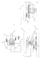
図61は、従来の第2例による2軸平行・1軸旋回運動案内機構の一部破断分解斜視図である。
図61は、従来技術の第2例による2軸平行・1軸旋回運動案内機構を用いた2軸平行・1軸旋回テーブル装置であり、同図(a)はテーブルを省略して2点鎖線で示す平面図、同図(b)は正面図である。
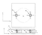
図62は、従来技術の第2例によるテーブルの平面図である。
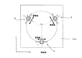
図62のように、2軸平行・1軸旋回運動案内機構201は、2軸平行運動案内部270と、この2軸平行運動案内部270に組み付けられる旋回運動案内部280と、から構成されている。
また、2軸平行・1軸旋回運動案内機構201を用いた2軸平行・旋回テーブル装置は、図61、図62に示すように、4つの2軸平行・1軸旋回運動案内機構201A,201B,201C,201Dを介して、テーブル233を基台234に対して平行に互いに直交する2軸方向に移動自在に支持し、テーブル233中央部に位置する旋回軸C0を中心にして旋回可能となっている。
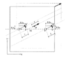
4つのうち3つの2軸平行・1軸旋回運動案内機構201A,201B,201Dには、それぞれ直線方向に伸縮駆動される、回転モータ238と、この回転モータ238の回転運動を直線運動に変換する送りねじ機構239から構成される直線駆動機構237A,237B,237Dが作動連結されている。これにより、2軸平行・1軸旋回運動案内機構201Cは、自由に運動ができる。
前記テーブル233を平行移動させる場合は、2つの直線駆動機構237A,237Bもしくは、直線駆動機構237Cを駆動する。
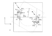
テーブル233を旋回軸C0に対して旋回させる場合、直線駆動機構237A,237Bとを互いに逆方向に図63に示すように同一量+ΔX,−ΔXだけ駆動させ、一方、直線駆動機構237DをY軸方向に所定量ΔYだけ駆動させる。
このように、従来技術における2軸平行・1軸旋回運動案内機構およびこれを用いた2軸平行・1軸旋回テーブル装置は、テーブルを平行移動または旋回させ、位置決めを行うようにしている。
【特許文献1】
特開2002−328191号公報(図1、図2)
【特許文献2】
特開平11−245128号公報(図2、図4、図5)
【発明の開示】
【発明が解決しようとする課題】
【0003】
従来技術の第1例のリニアモータを内蔵したステージ装置は、XYθの3方向の各軸が重なりあった装置構成となっていて、位置決めする対象物が大型化すると、ステージ装置が物理的に高くなるという問題があった。近年、液晶材料は年々大型化しており、テーブル即ちステージの往復移動や回転移動させるためには、リニアモータやステージ装置をそのまま大きくせざるを得ず、ステージ装置の重心が高くなると、振動等の外乱に弱いという欠点もあった。
また、XYθの3方向の各軸が重なりあった装置構成のため、ステージが大型化した場合、XYが移動すると、重心位置がずれる。このため、駆動部によるステージの移動位置によっては、各軸の連結部に荷重が集中し、ステージに大きなモーメント荷重が発生することになり、ステージの円滑な移動が妨げられたり、意図しない回転移動が生じたりして、位置決め精度が低下する問題がある。
【0004】
また、従来技術の第2例の2軸平行・1軸旋回運動案内機構およびこれを用いた2軸平行・1軸旋回テーブル装置は、2軸平行・1軸旋回運動案内機構をテーブルの4隅のうちの3つに配置した、3軸構成となっている。このため、1軸のみで駆動する方向があり、モータの容量が不均一のため、2軸を駆動させる方向と同じ性能を発揮することができないので、1軸のみで駆動する方向では、移動・位置決めに時間が掛かり、結果的に効率性・生産性が悪くなるという問題があった。
また、ボールねじ駆動なので、バックラッシュ等のメカロスが存在した。
さらに、大型化したテーブルを移動するような場合は、1軸駆動では、テーブルの片側で駆動することにとなるので、駆動軸の無いテーブル片側が遅れて移動し、テーブル位置決め精度が低下するというような問題もあった。
【0005】
加えて、テーブル上の対象物の加工などが行われる際に、外力が掛かると、制御系で保持しない並進自由度や、回転自由度が存在するので、テーブルが外力に従い移動する場合がある。この後、外力によるテーブルや対象物の移動を把握する部が無いので、テーブル位置を補正できない問題があった。
【0006】
本発明は、このような問題点に鑑みてなされたもので、テーブルが大型化しても、装置の高さを抑えて構成するとともに、テーブルや対象物による荷重をバランス良く分散して支持し、さらに、駆動力をバランスよく作用させることで、各方向への並進移動、回転移動を同じような性能で、精度良く、効率的に動作させ、加えて、テーブルに外力が加わって、テーブルが移動した場合にも、再度テーブルを補正できるアライメント装置を提供することを目的とする。
【課題を解決するための部】
【0007】
上記問題を解決するため、本発明は、次のように構成したものである。
請求項1に記載の発明は、機台部に配置された駆動機構を介して対象物を搭載するテーブルを所定の位置に位置決めするアライメント装置において、前記駆動機構は、並進自由度を持つ2つの並進駆動部と、回転自由度を持つ1つの回転駆動部とよりなる機構部と、2つの前記並進駆動部と1つの前記回転駆動部にそれぞれ該駆動部を駆動するための3つの電動機と、被検出体となる該機構部の動作量を検出する検出部と、指令信号を受けて前記電動機を制御する制御器とよりなる電動機制御装置と、から構成される並進駆動・並進・回転自由度機構モジュールを少なくも2組備えたものであり、前記並進駆動・並進・回転自由度機構モジュールは、前記制御器に動作指令を与える指令装置を備えると共に、前記電動機により、2つの前記並進駆動部と1つの前記回転駆動部を動作させることにより、前記テーブルを2方向の並進移動もしくは回転移動させるようにしたことを特徴とするものである。
また、請求項2に記載の発明は、前記並進駆動・並進・回転自由度機構モジュールは、少なくとも1つの並進駆動部と、1つの回転駆動部とからなり、前記回転駆動部の回転中心が、回転中心から同一半径上に配置され、前記回転中心に対して軸対称に配置されていることを特徴とするものである。
また、請求項3に記載の発明は、前記並進駆動・並進・回転自由度機構モジュールは、前記並進駆動部の移動方向の1つが回転中心に一致するように配置されていることを特徴とするものである。
また、請求項4に記載の発明は、前記並進駆動・並進・回転自由度機構モジュールは、2自由度を有する前記並進駆動部の上部または下部に、前記回転駆動部を備えていることを特徴とするものである。
また、請求項5に記載の発明は、前記並進駆動・並進・回転自由度機構モジュールは、少なくとも1自由度を有する前記並進駆動部の上部に、前記回転駆動部が配置され、該回転駆動部の上部に、少なくとも1自由度を有する前記並進駆動部が配置されていることを特徴とするものである。
【0008】
本発明によれば、次のような効果がある。
本発明によると、装置の高さを抑えてXYθの3方向へ動作するテーブルを実現でき、テーブルや対象物の荷重を、バランス良く分散して支持することができ、さらに、テーブルを移動する駆動力を、バランス良く分散して出力できるので、テーブルの並進移動や回転移動では、どの方向にも各リニアモータが動作し、重心から偏らずに動作するので、均一な性能で、精度良く、効率的に動作させることができる。
また、本発明によると、テーブルや対象物の荷重を、バランス良く分散して支持することができ、さらに、テーブルを移動する駆動力を、バランス良く分散して出力できるので、どの方向にも各リニアモータが動作し、重心から偏らずに動作する状況に加えて、特定の方向に必要な駆動出力を追加することができる。
また、本発明によると、テーブルの回転角度や並進動作量がわかれば、テーブルの動作量と各リニアモータの動作量が幾何学的な関係によって決定されるので、各並進駆動・並進・回転自由度機構モジュールの並進駆動部の動作量を算出し、動作指令として用いることができる。
また、本発明によると、テーブル上の対象物の配置状況を2次元位置センサを用いて位置の補正値を算出することで、テーブル移動動作を迅速に行うことができる。
また、本発明によると、2つの並進自由度案内部の取り付け角度が固定なので、テーブル移動する際に必要な動作量を比較的簡単に演算することができる。
また、本発明によると、2つの並進駆動部の直動案内を挟んで回転駆動部を置くことができ、テーブルから機台まで連続して支持できるので、テーブル他の荷重に対して、並進駆動・並進・回転自由度機構モジュールが変形を抑制して支持することができる。
また、本発明によると、テーブルの平面内の動作を抑制せずにテーブルや対象物の荷重を、バランス良く分散して支持することができる。
また、本発明によると、XYθの3方向へ動作するテーブルを実現でき、テーブルや対象物の荷重を、バランス良く分散して支持することができ、さらに、テーブルを移動する駆動力を、バランス良く分散して出力できるので、テーブルの並進移動や回転移動では、どの方向にも各並進駆動・並進・回転自由度機構モジュールが動作し、重心から偏らずに動作するので、均一な性能で、精度良く、効率的に動作させることができる。
また、本発明によると、並進駆動・並進・回転自由度機構モジュールの回転駆動部の中心が、テーブル中心から同一半径上に配置され、テーブル中心軸対象に配置されているので、重心の偏りが生じることなく、動作できることにより精度良く動作させることができる。
また、本発明によると、並進駆動部の1つの移動方向が回転中心に一致することにより、テーブル移動に必要な動作量を比較的簡単に演算することができる。
また、本発明によると、2つの並進駆動部の取り付け角度が固定なので、テーブル移動する際に必要な動作量を比較的簡単に演算することができる。
また、本発明によると、2つの並進駆動部に挟まれて回転駆動部が配置されることにより、テーブルから機台まで連続して支持できるので、並進駆動・並進・回転自由度機構モジュールの変形が抑制され、テーブルは精度良く位置決めされる。
また、本発明によると、テーブル上の対象物の位置が2次元位置センサにより求められ、位置の補正値が算出される補正量算出部を具備したことにより、テーブルに位置ずれが生じた場合でも、テーブルは所定の位置へ確実に位置決めされる。
また、本発明によると、テーブル上の対象物の配置状況を2次元位置センサの検出信号により位置の補正値を算出することで、テーブル移動動作を迅速に行うことができる。
また、本発明によると、前記回転駆動部が移動した後に、並進駆動部が移動するように指令を生成する指令部を具備したことにより、補正量の算出が容易となり、テーブルは効率的に位置決めされる。
【図面の簡単な説明】
【0009】
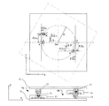
【図1】本発明の第1実施例を示すアライメント装置の概略図
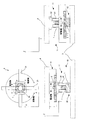
【図2】本発明の第1実施例を示すアライメント装置の構成図
【図3】本発明の第1実施例を示すアライメント装置に使用する並進駆動・並進・回転自由度機構モジュールの概略図で、(a)は平面図、(b)は正面図(c)は側面図
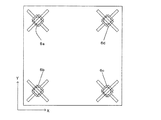
【図4】本発明の第1実施例を示すアライメント装置の上面図および並進駆動・並進・回転自由度機構モジュールの配置例1を示す図
【図5】本発明の第1実施例を示すアライメント装置のテーブルの回転移動を示す図
【図6】本発明の第1実施例を示すアライメント装置のテーブルの並進移動を示す図
【図7】本発明の第1実施例を示すアライメント装置の2次元位置センサによる対象物の配置図および位置補正方法を示す図
【図8】本発明の第1実施例を示すアライメント装置の上面図および並進駆動・並進・回転自由度機構モジュールの配置例2を示す図
【図9】本発明の第1実施例を示すアライメント装置の上面図および並進駆動・並進・回転自由度機構モジュールの配置例3を示す図
【図10】本発明の第1実施例を示すアライメント装置の上面図および並進駆動・並進・回転自由度機構モジュールの配置例4を示す図
【図11】本発明の第1実施例を示すアライメント装置の並進駆動・並進・回転自由度機構モジュールの配置例4におけるテーブルの回転移動を示す図
【図12】本発明の第1実施例を示すアライメント装置の上面図および並進駆動・並進・回転自由度機構モジュールの配置例5を示す図
【図13】本発明の第1実施例を示すアライメント装置の上面図および並進駆動・並進・回転自由度機構モジュールの配置例6を示す図
【図14】本発明の第1実施例を示すアライメント装置の上面図および並進駆動・並進・回転自由度機構モジュールの配置例7を示す図
【図15】本発明の第1実施例を示すアライメント装置の上面図および並進駆動・並進・回転自由度機構モジュールの配置例8を示す図
【図16】本発明の第1実施例を示すアライメント装置の上面図および並進駆動・並進・回転自由度機構モジュールの配置例9を示す図
【図17】本発明の第1実施例を示すアライメント装置の上面図および並進駆動・並進・回転自由度機構モジュールの配置例10を示す図
【図18】本発明の第1実施例を示すアライメント装置の上面図および並進駆動・並進・回転自由度機構モジュールの配置例11を示す図
【図19】本発明の第1実施例を示すアライメント装置の上面図および並進駆動・並進・回転自由度機構モジュールの配置例12を示す図
【図20】本発明の第1実施例を示すアライメント装置の上面図および並進駆動・並進・回転自由度機構モジュールの配置例13を示す図
【図21】本発明の第1実施例を示すアライメント装置の上面図および並進駆動・並進・回転自由度機構モジュールの配置例14を示す図
【図22】本発明の第1実施例を示すアライメント装置の上面図および並進駆動・並進・回転自由度機構モジュールの配置例15を示す図
【図23】本発明の第1実施例を示すアライメント装置の上面図および並進駆動・並進・回転自由度機構モジュールの配置例16を示す図
【図24】本発明の第1実施例を示すアライメント装置の上面図および並進駆動・並進・回転自由度機構モジュールの配置例17を示す図
【図25】本発明の第1実施例を示すアライメント装置の上面図および並進駆動・並進・回転自由度機構モジュールの配置例18を示す図
【図26】本発明の第1実施例を示すアライメント装置の上面図および並進駆動・並進・回転自由度機構モジュールの配置例19を示す図
【図27】本発明の第2実施例を示すアライメント装置の構成図
【図28】本発明の第2実施例を示すアライメント装置に使用する並進駆動・並進・回転自由度機構モジュールの概略図で、(a)は平面図、(b)は正面図(c)は側面図
【図29】本発明の第2実施例を示すアライメント装置のテーブルの回転移動を示す図
【図30】本発明の第2実施例を示すアライメント装置のテーブルの並進移動を示す図
【図31】本発明の第3実施例を示すアライメント装置に使用する3自由度モジュールの概略図で、(a)は平面図、(b)は正面図(c)は側面図
【図32】本発明の第3実施例を示すアライメント装置の上面図および並進駆動・並進・回転自由度機構モジュールと3自由度モジュールの配置例1を示す図
【図33】本発明の第3実施例を示すアライメント装置の上面図および並進駆動・並進・回転自由度機構モジュールと3自由度モジュールの配置例2を示す図
【図34】本発明の第4実施例を示すアライメント装置の上面図および並進駆動・並進・回転自由度機構モジュールの配置例1を示す図
【図35】本発明の第5実施例を示すアライメント装置を示す模式図
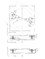
【図36】本発明の第5実施例を示す並進回転駆動機構の上面および側面図
【図37】本発明の第5実施例を示すアライメント装置の上面図および側面図
【図38】本発明の第5実施例を示すアライメント装置のテーブルの回転移動を示す図
【図39】本発明の第5実施例を示すアライメント装置のテーブルの並進移動を示す図
【図40】本発明の第6実施例を示す並進回転駆動機構の上面図および側面図
【図41】本発明の第7実施例を示すアライメント装置を示す模式図
【図42】本発明の第7実施例を示す並進回転駆動機構の上面および側面図
【図43】本発明の第7実施例を示すアライメント装置の並進回転駆動機構の配置およびテーブルの回転移動を示す図
【図44】本発明の第7実施例を示す位置補正方法を示す模式図
【図45】本発明の第8実施例を示す並進回転駆動機構の配置およびテーブルの回転移動を示す図
【図46】本発明の第9実施例を示す並進回転駆動機構の配置およびテーブルの回転移動を示す図
【図47】本発明の第9実施例を示す並進回転駆動機構の配置およびテーブルの回転移動を示す図
【図48】本発明の第10実施例を示すアライメント装置の上面図
【図49】本発明の第11実施例を示すアライメント装置の上面図
【図50】本発明の第12実施例を示すアライメント装置上面図
【図51】本発明の第13実施例を示すアライメント装置の上面図(その他の変形配置例1)
【図52】本発明の第13実施例を示すアライメント装置の上面図(その他の変形配置例2)
【図53】本発明の第13実施例を示すアライメント装置の上面図(その他の変形配置例3)
【図54】本発明の第13実施例を示すアライメント装置の上面図(その他の変形配置例4)
【図55】本発明の第13実施例を示すアライメント装置の上面図(その他の変形配置例5)
【図56】本発明の第13実施例を示すアライメント装置の上面図(その他の変形配置例6)
【図57】本発明の第13実施例を示すアライメント装置の上面図(その他の変形配置例7)
【図58】本発明の第13実施例を示すアライメント装置の上面図(その他の変形配置例8)
【図59】第1の従来例のリニアモータを内蔵したステージ装置の正面図
【図60】第1の従来例のリニアモータを内蔵したステージ装置の平面図
【図61】第2の従来例の2軸平行・1軸旋回運動案内機構の一部破断分解斜視図
【図62】第2の従来例の2軸平行・1軸旋回テーブル装置の平面図および側面図同図(a)はテーブルを省略して2点鎖線で示す平面図、同図(b)は正面図
【図63】第2の従来例のテーブルの平面図
【符号の説明】
【0010】
1 リニアモータ
2 動作量検出部
3 制御器
4 テーブル
5 対象物
6 並進駆動・並進・回転自由度機構モジュール
7 機台部
8 指令部
9 2次元位置センサ
10 補正量算出部
11 並進駆動部
12 回転自由度案内部
13 並進自由度案内部
14 3自由度モジュール
15 動作量演算部
16 電動機
16L リニアモータ
16R 回転型モータ
17 回転駆動部
21 直動案内
22 直動案内ブロック
23 回転用軸受
101 第1ステージ
102 第2ステージ
103 回転ステージ
104 基台
105,106 直動案内ユニット
107 軌道レール
108 スライダ
109 ストッパ
110,114,115 コード
111 第1リニアモータ
112 第2リニアモータ
113 回転用リニアモータ
117 センサ
118 リニアスケール
119,121,122,125 突出部
120 テーブル
126 取付用ねじ孔
128 ベッド
134 第3リニアモータの一次側
141 取付用孔
139 第3リニアモータの二次側
201 2軸平行・1軸旋回運動案内機構
202 第1軌道レール
204 移動ブロック
205 ボール(転動体)
206 第2軌道レール
210 第1凹部
211 第2凹部
212 ボール転走溝(第1軌道レール)
213 ボール転走溝(第1凹部)
214 ボール逃がし通路
215 方向転換路
216 側蓋
217 ボール転走溝(第2軌道レール)
218 ボール転走溝(第2凹部)
219 ボール逃がし通路
220 方向転換路
221 側蓋
233 テーブル(第2部材)
234 基台(第1部材)
237 直線駆動機構
238 回転モータ
239 送りねじ機構
241 ナット
242 ねじ軸
243 ベアリング(複列アンギュラコンタクトタイプ)
244 ベアリングサポート
247 継手部材
249 ブレーキ機構
270 2軸平行運動案内部
280 旋回運動案内部
206 回転モータ
【発明を実施するための最良の形態】
【0011】
以下、本発明の実施の形態について図を参照して説明する。
【実施例1】
【0012】
本発明の第1実施例のアライメント装置の構成は、以下のようになっている。
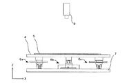
図1は、本発明の第1実施例を示すアライメント装置の概略図である。
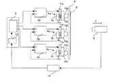
図2は、本発明の第1実施例を示すアライメント装置の構成図である。
図3は、本発明の第1実施例を示すアライメント装置に使用する並進駆動・並進・回転自由度機構モジュールの概略図で、(a)は平面図、(b)は正面図(c)は側面図である。
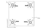
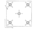
図4は、本発明の第1実施例を示すアライメント装置の上面図および並進駆動・並進・回転自由度機構モジュールの配置例1を示す図である。
図において、1(1a,1b,1c)はリニアモータ、2(2a,2b,2c)は動作量検出部、3(3a,3b,3c)は制御器、4はテーブル、5は対象物、6(6a,6b,6c)は並進駆動・並進・回転自由度機構モジュール、7は機台部、8は指令部、9は2次元位置センサ、10補正量算出部、11(11a,11b11c)は並進駆動部、12(12a,12b,12c)は回転自由度案内部、13(13a,13b,13c)は並進自由度案内部、15は動作量演算部、21は直動案内、22は直動案内ブロック、23は回転用軸受となっている。
【0013】
本発明が特許文献1と異なる部分は、リニアモータを重ねてXYθ方向へのテーブル移動を実現しているのでは無く、並進駆動・並進・回転自由度機構モジュール6を少なくとも3つ備えてXYθ方向へのテーブル移動を実現している部分である。
本発明が特許文献2と異なる部分は、並進駆動・並進・回転自由度機構モジュール6を少なくとも3つ備えて、その配置を均等配置して、各方向へのテーブル移動を偏りなく実現している部分である。
【0014】
図1のように、2次元位置センサ9が把握した対象物5の配置を、並進駆動・並進・回転自由度機構モジュール6(6a,6b,6c)が駆動して、テーブル4を移動して、位置の補正を行う。
並進駆動・並進・回転自由度機構モジュール6(6a,6b,6c)はテーブル4と機台部7に固定されている。
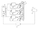
図2のように、テーブル4は並進駆動・並進・回転自由度機構モジュール6が、3つ(6a,6b,6c)付随し、並進駆動・並進・回転自由度機構モジュール6(6a,6b,6c)は、並進駆動部11(11a,11b,11c)と、回転自由度案内部12(12a,12b,12c)と、並進自由度案内部13(13a,13b,13c)から成り、並進駆動部11(11a,11b,11c)には、リニアモータ1(1a,1b,1c)が装着され、リニアモータ1(1a,1b,1c)は、指令部8に従い制御器3(3a,3b,3c)が動作を制御する。2次元位置センサ9が捕らえた対象物5の画像を画像処理して、対象物5があるべき配置位置を補正量算出部10が算出して得た値から指令部8は、テーブル4の動作量からリニアモータ1の動作量を各動作量演算部15にて算出し、各制御器3(3a,3b,3c)に補正量を指令する。
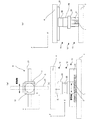
図3(a),(b),(c)のように、並進駆動・並進・回転自由度機構モジュール6は、リニアモータ1を有する並進駆動部11と、回転自由度案内部12と、並進自由度案内部13から成り、機台部7からテーブル4までの間に、並進自由度、並進自由度、回転自由度を順に有するように構成されている。
回転自由度案内部12には、回転用軸受23を有して回転自由度を実現し、並進駆動部11と並進自由度案内部13には、直動案内21を移動できる直動案内ブロック22を設けることで、並進自由度を実現している。
さらに、2つの並進自由度は、直交するように構成されている。
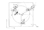
図4のように、図3で示した並進駆動・並進・回転自由度機構モジュール6(6a,6b,6c)が3つ有り、その初期位置が構成する正三角形の重心が、テーブル4の重心と一致するように、かつ、並進駆動部11(11a,11b,11c)のリニアモータ1(1a,1b,1c)が、テーブル4の中心から成す円の接線方向に駆動するように配置されている。
【0015】
次に、並進駆動・並進・回転自由度機構モジュール6と、これを用いたアライメント装置の動作について説明する。
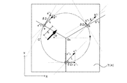
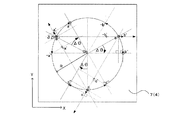
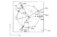
図5は本発明の第1実施例を示すアライメント装置のテーブルの回転移動を示す図である。
図5において、Ooはテーブルの中心および回転中心、Rは回転半径、δZiは並進駆動・並進・回転自由度機構モジュール6の並進駆動部11のリニアモータ1の動作量、Δθはテーブルの回転角度、a,b,cは並進・回転自由度機構モジュール6の並進駆動部11のリニアモータ1の初期位置、a’,b’,c’はδZi移動時の並進・回転自由度機構モジュール6の並進駆動部11のリニアモータ1の移動後の位置、a’’,b’’,c’’は並進・回転自由度機構モジュール6の回転自由度案内部12の移動後の位置である。
並進駆動・並進・回転自由度機構モジュール6(6a,6b,6c)の並進駆動部11(11a,11b,11c)のリニアモータ1(1a,1b,1c)を、同じ量だけ進めると、リニアモータ1aは初期位置aからa’へ、リニアモータ1bは初期位置bからb’へ、リニアモータ1cは初期位置cからc’へ、移動する。
並進駆動・並進・回転自由度機構モジュール6(6a,6b,6c)の上端と下端は、テーブル4と機台部7に固定されているが、並進自由度案内部13(13a,13b,13c)と回転自由度案内部12(12a,12b,12c)による並進自由度と回転自由度を有しているので、並進駆動・並進・回転自由度機構モジュール6aの直交関係がある並進自由度案内部13aは、他軸のリニアモータ1b、1cが動作するので、直動案内21が移動し、回転自由度案内部12aも回転する。
同様に、並進自由度案内部13bの直動案内21が移動し、回転自由度案内部12bも回転し、並進自由度案内部13cの直動案内21が移動し、回転自由度案内部12cも回転するので、テーブル4が回転運動する。
回転自由度案内部12(12a,12b,12c)は、並進自由度案内部13(13a,13b,13c)の上部に構成されているので、回転自由度案内部12(12a,12b,12c)は、回転運動の回転中心からの半径上(a’’,b’’,c’’)に移動することになる。
【0016】
均等かつテーブル中心に対して対象に並進駆動・並進・回転自由度機構モジュール6(6a,6b,6c)が配置されているため、各並進駆動・並進・回転自由度機構モジュール6(6a,6b,6c)の並進駆動部11のリニアモータ1(1a,1b,1c)を、同じ量だけ進めると、テーブル4はテーブル中心に対して回転移動する。
なお、リニアモータ1(1a,1b,1c)の移動範囲は有限のため、テーブル4の大きな回転角度の移動は不可能である。
【0017】
また、テーブルの中心を回転中心とするテーブル4の回転角度Δθと並進駆動部11(11a,11b,11c)のリニアモータ1(1a,1b,1c)の動作量δziの関係は図4のようになる。
つまり、並進駆動・並進・回転自由度機構モジュール6(6a,6b,6c)の初期配置位置は既知であるので、テーブル4の回転角度Δθが決まれば、並進駆動部11(11a,11b,11c)のリニアモータ1(1a,1b,1c)の動作量δziが求まることになる。
ここでは、テーブル4の中心を回転中心としたが、任意の位置を回転中心とした場合も、同様になり、回転中心の位置と回転角度から、各並進駆動・並進・回転自由度機構モジュール6(6a,6b,6c)のリニアモータ1(1a,1b,1c)の動作量δziが決まる。
よって、テーブル4の回転角度と各並進駆動・並進・回転自由度機構モジュール6(6a,6b,6c)のリニアモータ1(1a,1b,1c)の動作量δziの関係は幾何学的に決まり、指令部8が、これらの動作量として指令すれば、各制御器3は、動作量δziだけリニアモータ1を駆動することができる。
【0018】
図6は本発明の第1実施例を示すアライメント装置のテーブルの並進移動を示す図である。
図6において、Lはテーブル4の並進動作量、αはテーブル4の並進移動方向が成す角度、δZiは並進駆動・並進・回転自由度機構モジュール6の並進駆動部11のリニアモータ1の動作量a,b,cは並進・回転自由度機構モジュール6の並進駆動部11のリニアモータ1の初期位置a’’’1,b’’’1,c’’’1はδZi移動時の並進・回転自由度機構モジュール6の並進駆動部11のリニアモータ1の移動後の位置a’’’,b’’’,c’’’は並進・回転自由度機構モジュール6の回転自由度案内部12の移動後の位置である。
テーブル4を並進移動する場合も、テーブル4の並進動作量と方向と、並進駆動・並進・回転自由度機構モジュール6(6a,6b,6c)のリニアモータ1(1a,1b,1c)の各々の動作量δziが幾何学的に決定できる。
図6のように、リニアモータ1aが初期位置aからa’’’1へ、リニアモータ1bが初期位置bからb’’’1へ、リニアモータ1cが初期位置cからc’’’1へ、移動すると、テーブル4が並進移動する。
テーブル4の並進動作量は、リニアモータ1aの駆動方向の成分:aからa’’’1までと、並進自由度案内部13aの直動案内21の移動成分:a’’’1からa’’’までを合成した量に等しい。同様に、リニアモータ1bの駆動方向の成分:bからb’’’1と、並進自由度案内部13bの直動案内21の移動成分:b’’’1からb’’’、を合成した量に等しく、リニアモータ1cの駆動方向の成分:cからc’’’1と並進自由度案内部13cの直動案内21の移動成分:c’’1からc’’’を合成した量に等しい。
並進自由度案内部13aは、リニアモータ1bおよび1cの動作によってa’’’へ移動する。同様に、並進自由度案内部13b、13cはリニアモータ1a,1b,1cの動作によってb’’’へ移動する。
なお、テーブルに回転方向への力が掛からないので、回転自由度案内部12(12a,12b,12c)は作用しない。
以上のように、並進駆動・並進・回転自由度機構モジュール6を複数用いて、テーブル4を回転および並進移動することができる。
【0019】
次に、本発明の第1実施例の一連の動作を説明する。
アライメント装置のテーブル4に対象物5に置かれ、加工等の作業をするうえで、対象物5を加工側に合わせて配置する必要があるので、テーブル4を平面上で移動して、対象物5の位置を補正する必要が出てくる。
図7は本発明の第1実施例を示すアライメント装置の説明図で、(a)は2次元位置センサによる対象物の配置図を示し、(b)はおよび位置補正方法を示す図である。
図7(a)のように、テーブル4に置かれた対象物5の配置は、2次元位置センサ9で画像として認識できる。
この画像にて、補正量算出部10は、図7(b)のように、対象物5に予め記されたマークや対象物5の特徴を認識できれば、その傾きから、ある回転中心からの回転角度や、並進動作量を認識できる。
補正量算出部10が補正角度Ф、動作量Lを算出すると、動作量演算部15は、図5、図6で示したように、テーブル4の動作量から、幾何学的に各並進駆動・並進・回転自由度機構モジュール6の並進駆動部11のリニアモータ1の動作量がわかるので、指令部8に各軸の動作量を出力する。指令部8は、この各制御器3に動作量δziを指令する。各制御器3は、動作量δziを実行するように、各リニアモータ1を駆動するので、並進駆動・並進・回転自由度機構モジュール6が作用して、テーブル4を移動して、対象物5の位置を補正することができる。
対象物5の位置の補正が完了したあと、テーブル4上の対象物5の加工などが行われる際に、外力が掛かると、並進駆動・並進・回転自由度機構モジュール6には制御系で保持しない並進自由度の回転自由度案内部12や、回転自由度の並進自由度案内部13が存在するので、テーブル4が外力に従い移動する可能性がある。この場合、2次元位置センサ9でテーブル4上の対象物5の配置を認識できるので、再度、2次元位置センサ9の画像を基に、補正量算出部10が、テーブル4の補正量を算出し、前述のように補正できるのである。
【0020】
なお、本実施例では、図3のように、各並進駆動・並進・回転自由度機構モジュール6を配置したが、別の形態でも良い。
図8は本発明の第1実施例を示すアライメント装置の上面図および並進駆動・並進・回転自由度機構モジュールの配置例2を示す図である。
図9は本発明の第1実施例を示すアライメント装置の上面図および並進駆動・並進・回転自由度機構モジュールの配置例3を示す図である。
図3の配置を、テーブル中心に右回りに90度回転させた配置でも良いし、図3の配置を、テーブル中心に右回りに180度回転させて配置しても良い。また、図示しないが、図3の配置を、テーブル中心に任意の角度回転させた配置でも良い。
【0021】
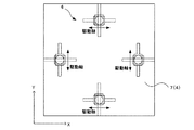
図10は本発明の第1実施例を示すアライメント装置の上面図および並進駆動・並進・回転自由度機構モジュールの配置例4を示す図である。
図11は本発明の第1実施例を示すアライメント装置の並進駆動・並進・回転自由度機構モジュールの配置例4におけるテーブルの回転移動を示す図である。
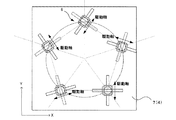
並進駆動・並進・回転自由度機構モジュール6が3つあれば、並進駆動部11・リニアモータ1の駆動方向を、正三角形を囲い込むように配置しても良い。
図11のように、この場合も、図5と同様に、テーブル4の回転角度θと各リニアモータ1の動作量δZiは幾何学的に決定できる。
リニアモータ1aが初期位置aからa’へ、リニアモータ1bが初期位置bからb’へ、リニアモータ1cが初期位置cからc’へ、移動すると、テーブル4が回転移動する。
これは、図5と同様に、任意の回転中心の回転移動とした場合も同様に幾何学的に、動作量δZiと回転移動の角度が決まる。並進移動も同様である。
【0022】
図12は本発明の第1実施例を示すアライメント装置の上面図および並進駆動・並進・回転自由度機構モジュールの配置例5を示す図である。
図13は本発明の第1実施例を示すアライメント装置の上面図および並進駆動・並進・回転自由度機構モジュールの配置例6を示す図である。
図12のように、並進駆動部11・リニアモータ1の駆動方向を、図10とは逆向きに正三角形を囲い込んだ配置でも良い。
さらに、図13のように、並進駆動・並進・回転自由度機構モジュール6を傾けて配置しても良く、リニアモータ1の正負の動作方向で他の並進自由度案内部11と回転自由度案内部12の方向が確定できるように配置すれば良い。
【0023】
さらに、本実施例では、並進駆動・並進・回転自由度機構モジュール6を3つ用いたが、これにこだわるものではない。
図14は本発明の第1実施例を示すアライメント装置の上面図および並進駆動・並進・回転自由度機構モジュールの配置例7を示す図である。
図15は本発明の第1実施例を示すアライメント装置の上面図および並進駆動・並進・回転自由度機構モジュールの配置例8を示す図である。
図16は本発明の第1実施例を示すアライメント装置の上面図および並進駆動・並進・回転自由度機構モジュールの配置例9を示す図である。
図17は本発明の第1実施例を示すアライメント装置の上面図および並進駆動・並進・回転自由度機構モジュールの配置例10を示す図である。
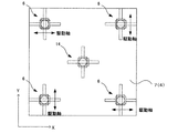
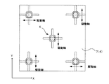
図14〜図17のように4つの並進駆動・並進・回転自由度機構モジュール6を配置して構成しても良い。
テーブルの回転移動や並進移動と、各リニアモータの動作量の関係は幾何学的に決定できる。また、リニアモータ1の正負の動作方向で他の並進自由度案内部11と回転自由度案内部12の方向が確定できるように配置すれば良い。
【0024】
図18は本発明の第1実施例を示すアライメント装置の上面図および並進駆動・並進・回転自由度機構モジュールの配置例11を示す図である。
図19は本発明の第1実施例を示すアライメント装置の上面図および並進駆動・並進・回転自由度機構モジュールの配置例12を示す図である。
図20は本発明の第1実施例を示すアライメント装置の上面図および並進駆動・並進・回転自由度機構モジュールの配置例13を示す図である。
図18〜図20は5つの並進駆動・並進・回転自由度機構モジュール6を配置した例であるが、前述と同様に、テーブル4の回転移動や並進移動と、各リニアモータ1の動作量の関係は幾何学的に決定できる。また、リニアモータ1の正負の動作方向で他の並進自由度案内部11と回転自由度案内部12の方向が確定できるように配置すれば良い。
【0025】
図21は本発明の第1実施例を示すアライメント装置の上面図および並進駆動・並進・回転自由度機構モジュールの配置例14を示す図である。
図21は6つの並進駆動・並進・回転自由度機構モジュール6を配置した例であるが、同様に、テーブルの回転移動や並進移動と、各リニアモータの動作量の関係は幾何学的に決定できる。また、リニアモータ1の正負の動作方向で他の並進自由度案内部11と回転自由度案内部12の方向が確定できるように配置すれば良い。
さらに、図示していないが、7つの並進駆動・並進・回転自由度機構モジュール6を配置しても良い。
【0026】
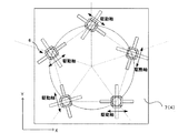
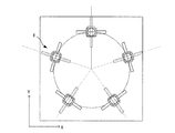
図22は本発明の第1実施例を示すアライメント装置の上面図および並進駆動・並進・回転自由度機構モジュールの配置例15を示す図である。
図22は6つの並進駆動・並進・回転自由度機構モジュール6を配置した例であるが、テーブル4の中心から2種類の正三角形を成すように、構成している。
テーブルの回転移動や並進移動と、各リニアモータの動作量の関係は幾何学的に決定できる。また、リニアモータ1の正負の動作方向で他の並進自由度案内部11と回転自由度案内部12の方向が確定できるように配置すれば良い。
【0027】
図23は本発明の第1実施例を示すアライメント装置の上面図および並進駆動・並進・回転自由度機構モジュールの配置例16を示す図である。
図24は本発明の第1実施例を示すアライメント装置の上面図および並進駆動・並進・回転自由度機構モジュールの配置例17を示す図である。
図25は本発明の第1実施例を示すアライメント装置の上面図および並進駆動・並進・回転自由度機構モジュールの配置例18を示す図である。
図26は本発明の第1実施例を示すアライメント装置の上面図および並進駆動・並進・回転自由度機構モジュールの配置例19を示す図である。
図23〜図26は8つの並進駆動・並進・回転自由度機構モジュール6を配置した例であるが、前述と同様に、テーブル4の回転移動や並進移動と、各リニアモータの動作量の関係は幾何学的に決定できる。また、図22のように、テーブル4の中心から並進駆動・並進・回転自由度機構モジュール6の初期位置が複数の半径を構成するように配置しても良く、また、リニアモータ1の正負の動作方向で他の並進自由度案内部11と回転自由度案内部12の方向が確定できるように配置すれば良い。
【0028】
図示した例にこだわらず、少なくとも3つの並進駆動・並進・回転自由度機構モジュールを有し、リニアモータ1の正負の動作方向で他の並進自由度案内部11と回転自由度案内部12の方向が確定できるように配置すれば良い。
テーブルの回転移動や並進移動と、各リニアモータの動作量の関係は幾何学的に決定できる。
これにより、テーブル4が大型化して重荷重になっても、バランスよく並進駆動・並進・回転自由度機構モジュール6が荷重を支持し、さらに、バランスよくテーブル4を各方向への並進移動や、回転移動を行うことができるのである。
【実施例2】
【0029】
本発明の第2実施例のアライメント装置の構成は、以下のようになっている。
図27は本発明の第2実施例を示すアライメント装置構成図である。
図28は本発明の第2実施例を示すアライメント装置に使用する並進駆動・並進・回転自由度機構モジュールの概略図である。
図において、1(1a,1b,1c)はリニアモータ、2(2a,2b,2c)は動作量検出部、3(3a,3b,3c)は制御器、4はテーブル、5は対象物、6(6a,6b,6c)は並進駆動・並進・回転自由度機構モジュール、7は機台部、8は指令部、9は2次元位置センサ、10補正量算出部、11(11a,11b,11c)は並進駆動部、12(12a,12b,12c)は回転自由度案内部、13(13a,13b,13c)は並進自由度案内部、21は直動案内、22は直動案内ブロック、23は回転用軸受となっている。
【0030】
本発明の第2実施例の概略は、第1実施例の図1と同じであり、並進駆動・並進・回転自由度機構モジュール6の配置は第1実施例の図3と同じである。
本発明の第2実施例が、第1実施例と異なる部分は、並進駆動・並進・回転自由度機構モジュール6の構成である。
図28のように、並進駆動・並進・回転自由度機構モジュール6は、リニアモータ1を有する並進駆動部11と、回転自由度案内部12と、並進自由度案内部13から成り、機台部7からテーブル4までの間に、並進自由度、回転自由度、並進自由度を順に有するように構成されている。
図4とは、回転自由度、並進自由度の順番が異なり、2つの並進自由度が、回転自由度を介して構成しているため、並進駆動部11と並進自由度案内部13が成す角度が変わる点が、第1実施例とは異なる。
【0031】
第1実施例と同様に、2次元位置センサ9が把握した対象物5の配置を、並進駆動・並進・回転自由度機構モジュール6(6a,6b,6c)が駆動して、テーブル4を移動して、位置の補正を行う。
並進駆動・並進・回転自由度機構モジュール6の構成が異なる以外は、機能や基本的な動作は第1実施例と同様である。
並進駆動・並進・回転自由度機構モジュール6の構成が、第1実施例は異なるので、テーブル4の移動と、並進駆動・並進・回転自由度機構モジュール6の並進駆動部11のリニアモータ1の動作量の幾何学的な関係が異なる。
図29は本発明の第2実施例を示すアライメント装置のテーブルの回転移動を示す図である。
図30は本発明の第2実施例を示すアライメント装置のテーブルの並進移動を示す図である。
図29において、Ooはテーブルの中心および回転中心、Rは回転半径、δZiは並進駆動・並進・回転自由度機構モジュール6の並進駆動部11のリニアモータ1の動作量、Δθはテーブルの回転角度、a,b,cは並進・回転自由度機構モジュール6の並進駆動部11のリニアモータ1の初期位置、a’,b’,c’はδZi移動時の並進・回転自由度機構モジュール6の並進駆動部11のリニアモータ1の移動後の位置、a’’,b’’,c’’は並進・回転自由度機構モジュール6の並進自由度案内部13の移動後の位置である。
テーブル4の回転移動は、2つの並進自由度が、回転自由度を介して構成しているため、並進駆動部11と並進自由度案内部13が成す角度が変わる。
図29のように、テーブル中心Ooを中心にΔθ回転するには、並進駆動部11aのリニアモータ1aの初期位置aからa’までの移動によるδZ1が必要になる。第1実施例の場合は、2つの並進自由度は、直交が固定される構成なので、図中のδZ1−1だけ移動すれば、テーブル4をΔθ回転できたが、2つの並進自由度が回転自由度を介して連結され、2つの並進自由度が成す角度が変わるので、図中のδZ1−2の成分を第1実施例の場合の動作量δZ1−1に追加する必要がある。
これらのδZ1−1、δZ1−2は、図29のように、幾何学的に求められる。
他の並進・回転自由度機構モジュール6b、6cも同様に、並進駆動部11b、11cのリニアモータ1b、1cの初期位置bからb’、cからc’までの移動によるδZ2、δZ3が幾何学的に求めることができる。
図30において、Lはテーブル4の並進動作量、αはテーブル4の並進移動方向が成す角度、δZiはは並進駆動・並進・回転自由度機構モジュール6の並進駆動部11のリニアモータ1の動作量、a,b,cは並進・回転自由度機構モジュール6の並進駆動部11のリニアモータ1の初期位置、a’’’1,b’’’1,c’’’1はδZi移動時の並進・回転自由度機構モジュール6の並進駆動部11のリニアモータ1の移動後の位置、a’’’,b’’’,c’’’は並進・回転自由度機構モジュール6の並進自由度案内部13の移動後の位置である。
【0032】
テーブル4の並進移動では、回転成分が発生しないので、並進・回転自由度機構モジュール6の回転自由度案内部12は作用しない。よって、テーブル4の並進移動の場合の各リニアモータ1の動作量は、第1実施例と同じ幾何学的関係となり、同様に算出できる。
本発明の第2実施例の一連の動作は、第1実施例と同様になる。
2次元位置センサ9や補正量算出部10の機能は変わらず、並進・回転自由度機構モジュール6の構成が異なるだけなので、動作量演算部15が各リニアモータ1の動作量を算出する際に用いる回転移動の幾何学的関係が異なり、第1実施例とは異なる値を動作量演算部15が算出する。
その後、第1実施例と同様に、各リニアモータ1を動作させ、テーブル4を移動して、対象物5の位置を補正する。
対象物5の位置の補正が完了したあと、第1実施例と同様に、再度、2次元位置センサ9により対象物5の位置を把握し、再度、対象物5の位置の補正を実施しても良い。
【0033】
なお、本実施例では、並進駆動・並進・回転自由度機構モジュール6の配置を図27のように示したが、これにこだわるものではなく、第1実施例で示したように図8〜図10、図12〜図26のように配置しても良い。
テーブル4の動作量と並進駆動・並進・回転自由度機構モジュール6のリニアモータ1の動作量は幾何学的な関係がある。
【実施例3】
【0034】
本発明の第3実施例のアライメント装置の構成は以下のようになっている。
図31は本発明の第3実施例を示すアライメント装置に使用する3自由度モジュールの概略図である。
図32は本発明の第3実施例を示すアライメント装置の上面図および並進駆動・並進・回転自由度機構モジュールと3自由度モジュールの配置例1を示す図である。
図33は本発明の第3実施例を示すアライメント装置の上面図および並進駆動・並進・回転自由度機構モジュールと3自由度モジュールの配置例2を示す図である。
図において、4はテーブル、6は並進駆動・並進・回転自由度機構モジュール、12は回転自由度案内部、13は並進自由度案内部、14は3自由度モジュール、21は直動案内、22は直動案内ブロック、23は回転用軸受となっている。
全体の構成は、第1実施例や第2実施例と同様な構成となっていて、リニアモータ1、動作量検出部2、制御器3、テーブル4、対象物5、並進駆動・並進・回転自由度機構モジュール6、機台部7、指令部8、2次元位置センサ9、補正量算出部10、並進駆動部11、回転自由度案内部12、並進自由度案内部13、動作量演算部15、直動案内21、直動案内ブロック22、回転用軸受23を備えている。
3自由度モジュール14は、並進駆動・並進・回転自由度機構モジュール6のように駆動源を持たず、1つの回転と2つの並進自由度を持つ機構であり、第1実施例の図3の並進駆動・並進・回転自由度機構モジュール6のように並進、並進、回転の順に機台部7からテーブル4に掛けて構成しても良いし、第2実施例の図28の並進駆動・並進・回転自由度機構モジュール6のように、並進、回転、並進の順に機台部7からテーブル4に掛けて構成しても良い。
また、並進駆動・並進・回転自由度機構モジュール6の構成も、第1実施例もしくは第2実施例の構成である。
並進駆動・並進・回転自由度機構モジュール6の配置を図32と図33に示したが、第1実施例の図4や、図8〜図10、図12〜図26に3自由度モジュール14を追加して構成しても良い。
【0035】
本発明の第3実施例が、第1実施例もしくは第2実施例と異なる部分は、3自由度モジュール14を追加した構成である点である。
また、第3実施例では、図32、図33のように、4つの並進駆動・並進・回転自由度機構モジュール6を用いた例と、8つの並進駆動・並進・回転自由度機構モジュール6を配置した例を図示している。
並進駆動・並進・回転自由度機構モジュール6と、これを用いたアライメント装置の動作も、前記の第1実施例、第2実施例と同様である。
3自由度モジュール14は、駆動源が無く、3自由度を有しているので、テーブル4の駆動に従い、各自由度が作用して、テーブル4の移動を妨げない。
テーブル4が大型化すると、重量が大きくなり、テーブル4自体がたわみ、平面精度が低下する場合があるが、3自由度モジュール14で支持すれば、テーブル4の変形を抑制し、平面精度を維持することができるようになる。
【実施例4】
【0036】
図34に本発明の第4実施例を示すアライメント装置の上面図および並進駆動・並進・回転自由度機構モジュールの配置例1を示す図を示す。
図34は、実施例1の図14に、並進駆動・並進・回転自由度機構モジュール6を追加した構成になっている。
全体の構成は、第1実施例や第2実施例、第3実施例と同様な構成となっていて、リニアモータ1、動作量検出部2、制御器3、テーブル4、対象物5、並進駆動・並進・回転自由度機構モジュール6、機台部7、指令部8、2次元位置センサ9、補正量算出部10、並進駆動部11、回転自由度案内部12、並進自由度案内部13、動作量演算部15、直動案内21、直動案内ブロック22、回転用軸受23を備えている。
【0037】
本発明の第4実施例が、第1実施例、第2実施例、第3実施例と異なる部分は、テーブル4および機台部7に対して、均等に配置された並進駆動・並進・回転自由度機構モジュール6にさらに、並進駆動・並進・回転自由度機構モジュール6を追加して、一方向だけリニアモータ1が増加した構成になっている点である。
本実施例においても、テーブル4の移動は、第1実施例、第2実施例、第3実施例と同様に行うことができる。
テーブル4の移動と、各リニアモータの動作量δZiは幾何学的に決定でき、指令部8にて動作量を指令すれば、テーブル4上の対象物5の位置の補正を実施できる。
なお、本実施例では、実施例1の図14に、並進駆動・並進・回転自由度機構モジュール6を追加した構成したが、これにこだわるものではなく、第1実施例の図4、図8〜図10、図12〜図13、もしくは図15〜図26に並進駆動・並進・回転自由度機構モジュール6を追加して構成しても良い。
並進駆動・並進・回転自由度機構モジュール6は、制御器3によりリニアモータ1の機能を切り、フリーラン状態にすれば、3自由度を持つ3自由度モジュール14と同じ機能を有するので、不均一に配置された並進駆動・並進・回転自由度機構モジュール6をフリーラン状態にすれば、第3実施例と同じ作用および効果をもつ。
なお、並進駆動・並進・回転自由度機構モジュール6は、第1実施例の図4と、第2実施例の図28とあり、テーブル4とリニアモータ1との幾何学的な関係が変わるが、各々に適した指令を生成するようにすれば、2つの種類の並進駆動・並進・回転自由度機構モジュール6を混在して使用しても良い。
【実施例5】
【0038】
図35は、本発明の第5実施例を示すアライメント装置を示す模式図である。
図36は、本発明の第5実施例を示す並進駆動・並進・回転自由度機構モジュールの上面および側面図である。
図37は、本発明の第5実施例を示すアライメント装置の上面図である。
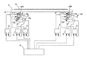
アライメント装置は、図35に示すようにテーブル下面に2つ配置された並進駆動・並進・回転自由度機構モジュール6指令部とから構成されている。
指令部8は、テーブル4の動作量として必要なリニアモータ16Lと回転型モータ16Rの動作量を算出して、各制御器3に動作量を指令する。リニアモータ16Lと回転型モータ16Rは、指令部8からの指令にしたがって6つの制御器3により動作が制御されている。
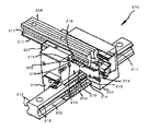
並進駆動・並進・回転自由度機構モジュール6は、図36に示すように2つの並進自由度部11と、回転型モータ1を有する1つ回転駆動部17とからなり、機台部7からテーブル4までの間に、並進駆動部11、回転駆動部17、並進駆動部11を順次配置されるように構成されている。並進駆動部11には、リニアモータ16Lが装着され、直動案内21を移動できる直動案内ブロック22を設けることで、並進自由に支持されている。回転駆動部17には回転型モータ16Rが装着され、回転用軸受23を設けることで回転自由に支持されている。2つの並進駆動部11の間に回転駆動部17があるため直交するとは限らない。
2個の第1および第2の並進駆動・並進・回転自由度機構モジュール6a,6bは、図37に示すように回転駆動部17の回転中心が、テーブル4の中心(Oo)から同一半径上でテーブル4の中心に対して軸対称になるように配置されている。
【0039】
本発明が特許文献1および特許文献2と異なる部分は、並進駆動・並進・回転自由度機構モジュール6を2つ備えてXYθ方向へのテーブル移動を実現している部分である。
【0040】
次に、アライメント装置の回転移動について図38を用いて説明する。図38は、本発明の第5実施例を示すアライメント装置のテーブルの回転移動を示す図である。Ooはテーブルの中心および回転中心、Rは回転半径、δZijは並進駆動・並進・回転自由度機構モジュール6の並進駆動部11の移動量、Δθはテーブルの回転角度、a,bは初期位置ある。
テーブル4の回転移動は、2つの並進駆動部11は、回転駆動部17を介して構成されているため、2つの並進駆動部11がなす角度は直交とは限らない。
図38のように、第1の並進駆動・並進・回転自由度機構モジュール6aの下部に配置された並進駆動部11の移動量はδZ1Y、上部に配置された並進駆動部11の移動量はδZ1X,回転駆動部17の移動量はδ1θとした場合、第2の並進駆動・並進・回転自由度機構モジュール6bの下部に配置された並進自由度部11の移動量はδZ2Y、上部に配置された並進駆動部11の移動量はδZ2X,回転駆動部17の移動量がδ2θになるように移動する。さらに、2つの並進駆動部11が回転駆動部17を介して配置され、2つの並進駆動部11がなす角度は直交ではないので、δε1の成分が動作量δZy1に追加されることにより、テーブル4はテーブル中心に回転移動する。
このように、テーブル4の移動量と並進駆動・並進・回転自由度機構モジュール6の各移動量は幾何学的に決まり、並進駆動部11と回転駆動部17の移動によりテーブル4はテーブル中心に回転移動する。
ここでは、テーブル4の中心Ooを基準としたが、任意の位置を回転中心としてもよく、幾何学的に並進駆動・並進・回転自由度機構モジュール6の各移動量がもとめられることにより任意の場所を回転中心として回転移動する。
次に、テーブルの並進移動について図39を用いて説明する。図39は本発明の第5実施例を示すアライメント装置のテーブルの並進移動を示す図である。Lはテーブル4の並進動作量、αはテーブル4の並進移動方向がなす角度、δZijは並進駆動・並進・回転自由度機構モジュール6の各並進自由度部の移動量である。テーブル4は、第1の並進駆動・並進・回転自由度機構モジュール6a,6bの上下部に配置された並進駆動部11に所定の移動量が指令され、位置決めされる。
このように、テーブル4の移動量と並進駆動・並進・回転自由度機構モジュール6の各移動量は幾何学的に決まり、並進駆動部11の移動により、テーブル4は並進移動する。回転駆動部17は作用せず、回転型モータ16Rは、テーブル4に回転方向への動きが生じないように保持する。
【0041】
以上のような構成にしたので、テーブル4の移動中や移動完了後に、対象物5が加工などされる際に、外力が作用しても、並進駆動・並進・回転自由度機構モジュール6は動作量検出部2によりテーブル4の位置を検出してフィードバック制御されているので、テーブル4の位置決め位置は保持される。
このように、テーブル4が大型化して重荷重になっても、荷重は2つの並進駆動・並進・回転自由度機構モジュール6で分散して支持され、外力がテーブル4に作用しても、位置が保持されることにより、テーブル4は、任意の位置へ精度良く位置決めされる。
【実施例6】
【0042】
次に、本発明の第6実施例を説明する。図40は本発明の第6実施例を示すテーブルの回転移動と並進駆動・並進・回転自由度機構モジュールの配置を示す側面図である。
実施例6の並進駆動・並進・回転自由度機構モジュール6aは、図36に示した実施例5と同じである。また、実施例6が実施例5と異なる部分は、第1の並進駆動・並進・回転自由度機構モジュール6aは、下部の並進駆動部11がX方向に駆動するように配置され、上部の並進駆動部11が、回転駆動部17の上にY方向に駆動するように配置されて構成されており、第2の並進駆動・並進・回転自由度機構モジュール6bは、下部の並進駆動部11がY方向に駆動するように配置され、上部の並進駆動部11が、回転駆動部17の上にX方向に駆動するように配置された構成されている点である。
動作については、並進駆動・並進・回転自由度機構モジュール6aが実施例5と同じであり、2つの第1および第2の並進駆動・並進・回転自由度機構モジュール6a,6bの並進駆動部11の配置の向きが相違しているが、幾何学的に求められる補正量から各駆動部へ指令すればよく、並進駆動部11と回転駆動部17の動作は実施例5と同様であるので省略する。
このように、テーブル4が大型化して重荷重になっても、荷重は2つの並進駆動・並進・回転自由度機構モジュール6で分散して支持され、外力がテーブル4に作用しても、位置が保持されることにより、テーブル4は、任意の位置へ精度良く位置決めされる。
【実施例7】
【0043】
次に、本発明の第7実施例を説明する。
図41は、本発明の第7実施例を示すアライメント装置を示す模式図である。
図42は、本発明の第7実施例を示す並進駆動・並進・回転自由度機構モジュールの上面および側面図である。
図43は、本発明の第7実施例を示すアライメント装置の並進駆動・並進・回転自由度機構モジュールの配置およびテーブルの回転移動を示す図である。
図41において、9は2次元位置センサ、10は補正量算出部である。
実施例7が実施例5、実施例6と異なる部分は、図41に示すように、テーブル上方に配置されたCCDカメラなどからなる2次元位置センサ9と、2次元位置センサ9の検出信号をもとに制御する補正量算出部10とを構成に加えた点と、テーブル下面に2つ配置された並進駆動・並進・回転自由度機構モジュール6が図42のような構成である点である。
2次元位置センサ9がモニタされた対象物5の画像は画像処理されて、対象物5があるべき配置位置が、補正量算出部10で算出されるので、対象物5があるべき配置になるように、第5例と同様にしてリニアモータ16Lと回転型モータ16Rを指令部8からの指令にしたがって6つの制御器3により動作を制御する。
並進駆動・並進・回転自由度機構モジュール6は、実施例5とは異なり図42に示すように、下から順次並進駆動部11と、並進駆動部11と、回転駆動部17とから構成されている。
また、2個の第1および第2の並進駆動・並進・回転自由度機構モジュール6a,6bは、実施例5と同様に、回転駆動部12の回転中心が、テーブル4の中心(Oo)から同一半径上でテーブル4の中心に対して軸対称になるように配置されている。
本発明が特許文献1および特許文献2と異なる部分は、並進駆動・並進・回転自由度機構モジュール6がテーブル4の下面に2つ備えられ、XYθ方向へテーブルが移動されている部分である。
【0044】
次に、実施例7のアライメント装置の回転移動について図43を用いて説明する。Ooはテーブルの中心および回転中心、Rは回転半径、δZijは並進駆動部11の移動量、Δθはテーブルの回転角度、a,bは初期位置である。
第1の並進駆動・並進・回転自由度機構モジュール6aの下部の並進駆動部11の移動量がδZ1Y、上部の並進駆動部11の移動量がδZ1X,回転駆動部12の移動量がδ1θとした時、第2の並進駆動・並進・回転自由度機構モジュール6bの下部の並進駆動部11の移動量がδZ2Y、上部の並進駆動部11の移動量がδZ2X,回転駆動部12の移動量がδ2θになるように移動することにより、テーブル4はテーブル中心に回転移動する。
図42のように並進駆動・並進・回転自由度機構モジュール6の構成が実施例5と異なるので、幾何学的な関係が変わり各電動機1の動作量が異なる点があるが、テーブル4の移動量と並進駆動・並進・回転自由度機構モジュール6の各移動量は、幾何学的に決まる点は同じであり、並進駆動部11と回転駆動部12の移動によりテーブル4はテーブル中心に回転移動する。
テーブルの並進移動については、回転駆動部17が動作せず、実施例5と同様の動作となるので省略する。
【0045】
次に、実施例7のアライメント装置の一連の動作について説明する。
図44は本発明の第7実施例を示す位置補正方法を示す模式図である。
テーブル4に置かれた対象物5の位置は、2次元位置センサ9で画像として認識される。補正量算出部10は、対象物5に予め記されたマークや対象物5の特徴(図中+で示す)を検出し、その傾き角からある回転中心からの回転角度や、並進動作量が求められる。
補正角度Ф、動作量Lが補正量算出部10により算出され、テーブル4の位置から、幾何学的に、並進駆動・並進・回転自由度機構モジュール6の各駆動部の動作量が求められ、指令部8は各制御器3に動作量δZijを指令され、テーブル4は位置決めされ、対象物5の位置は補正される。
ここで、テーブル4の移動中や移動完了後に、対象物5が加工などされる際に、外力が作用しても、並進駆動・並進・回転自由度機構モジュール6は動作量検出部2によりテーブル4の位置を検出してフィードバック制御されているので、テーブル4の位置決め位置は保持される。
このように、テーブル4が大型化して重荷重になっても、荷重は2つの並進駆動・並進・回転自由度機構モジュール6で分散して支持され、外力がテーブル4に作用しても、位置が保持されることにより、テーブル4は、任意の位置へ精度良く位置決めされる。
さらに、万が一テーブル4が外力により移動しても、2次元位置センサ9がテーブル4の移動を把握できるので、再び2次元の位置決めを行えばよい。
ここでは、並進駆動部11は、リニアモータ16Lを2台用いて説明したが、平面モータでも良く、平面内を自在に移動するものであれば良い。また、各駆動機構の駆動部を電磁型で説明したが、圧電型等でも良く、特に限定されるものではない。
【実施例8】
【0046】
次に、本発明の第8実施例を説明する。図45は、本発明の第8実施例を示すアライメント装置の並進駆動・並進・回転自由度機構モジュールの配置およびテーブルの回転移動を示す図である。
実施例8が実施例5および実施例6と異なる部分は、並進駆動・並進・回転自由度機構モジュール6の構成である。並進駆動・並進・回転自由度機構モジュール6の構成は、図42に示した実施例6と同じである。また、実施例7に示した2次元位置センサ9、補正量算出部10は省略する。
実施例8が実施例7と異なる部分は、第1の並進駆動・並進・回転自由度機構モジュール6aは、下部の並進駆動部11がX方向に駆動するように配置され、上部の並進駆動部11が、Y方向に駆動するように配置されて構成されており、第2の並進駆動・並進・回転自由度機構モジュール6bは、下部の並進駆動部11がY方向に駆動するように配置され、上部の並進駆動部11が、X方向に駆動するように配置された構成されている点である。
動作については、2個の第1および第2の並進駆動・並進・回転自由度機構モジュール6a,6bの並進駆動部11の配置が相違しているが、幾何学的に求められる補正量から各駆動部へ指令すればよく、並進駆動部11と回転駆動部12の動作は実施例6と同様であるので省略する。
このように、テーブル4が大型化して重荷重になっても、荷重は2つの並進駆動・並進・回転自由度機構モジュール6で分散して支持され、外力がテーブル4に作用しても、位置が保持されることにより、テーブル4は、任意の位置へ精度良く位置決めされる。
【実施例9】
【0047】
次に、本発明の第9の実施例について説明する。図46は本発明の第9実施例を示す並進駆動・並進・回転自由度機構モジュールの上面図および側面図である。
図47は、本発明の第9実施例を示す並進駆動・並進・回転自由度機構モジュールの配置およびテーブルの回転移動を示す図である。
実施例9が、実施例5から実施例8と異なる部分は、並進駆動・並進・回転自由度機構モジュール6の構成である。図46に示すように2つの並進駆動部11が回転駆動部17とからなり、機台部7からテーブル4までの間に、回転駆動部17、並進駆動部11、並進駆動部11を順次配置されるように構成されている点である。また、実施例7に示した2次元位置センサ9、補正量算出部10は省略する。
次に、アライメント装置の回転移動について図47を用いて説明する。(A)は2つの並進駆動・並進・回転自由度機構モジュール6の配置の向きが異なる場合であり、(B)は2つの並進駆動・並進・回転自由度機構モジュール6の配置の向きが同じ場合である。つまり、実施例5(図37)と実施例6(図40)、実施例7(図43)と実施例8(図45)の違いに相当する。
Ooはテーブルの中心および回転中心、Rは回転半径、δZijは並進駆動・並進・回転自由度機構モジュール6の並進駆動部11の移動量、Δθはテーブルの回転角度、a,bは初期位置ある。
(A)(B)いずれの場合も、X方向、Y方向、回転方向の各自由度の移動量は同じである。図46のように、第1の並進駆動・並進・回転自由度機構モジュール6aの下部に配置された並進駆動機構11の移動量はδZ1Y、上部に配置された並進駆動部11の移動量はδZ1X,回転駆動部17の移動量はδ1θとした場合、第2の並進駆動・並進・回転自由度機構モジュール6bの下部に配置された並進駆動部11の移動量はδZ2Y、上部に配置された並進駆動部11の移動量はδZ2X,回転駆動部17の移動量はδ2θ移動することにより、テーブル4はテーブル中心に回転移動する。
テーブルの並進移動については、回転駆動部17が動作しないことにより、実施例5と同様の動作となるので省略する。また、実施例9の一連の動作も実施例5や実施例7と同様であるので省略する。
以上のように実施例5から実施例9に示したように、並進駆動・並進・回転自由度機構モジュール6の構成が変わっても、テーブル4の移動量と各並進駆動・並進・回転自由度機構モジュール6の各駆動部の移動量とは幾何学的に求められる。
このように、テーブル4が大型化して重荷重になっても、荷重は2つの並進駆動・並進・回転自由度機構モジュール6で分散して支持され、外力がテーブル4に作用しても、位置が保持されることにより、テーブル4は、任意の位置へ精度良く位置決めされる。
【実施例10】
【0048】
次に、第10の実施例について説明する。図48は本発明の第10実施例を示すアライメント装置の上面図である。実施例10が、実施例5から9と異なる部分は、並進駆動・並進・回転自由度機構モジュール6の数であり、3つの並進駆動・並進・回転自由度機構モジュール6を用いている。また、実施例7に示した2次元位置センサ9、補正量算出部10は省略する。
アライメント装置の回転移動、並進移動およびテーブルの一連の動作については、並進駆動・並進・回転自由度機構モジュール6の個数が増えたに過ぎず同一であるので省略する。
並進駆動・並進・回転自由度機構モジュール6は、構成が実施例5から実施例9に示したいずれでも、さらに異なる構成の並進駆動・並進・回転自由度機構モジュール6が混在しても、また、その配置の向きがいずれの場合でも幾何学的に決定できる。
このように、テーブル4が大型化して重荷重になっても、荷重は3つの並進駆動・並進・回転自由度機構モジュール6で分散して支持され、外力がテーブル4に作用しても、位置が保持されることにより、テーブル4は、任意の位置へ精度良く位置決めされる。
【実施例11】
【0049】
次に、第11の実施例について説明する。図49は、本発明の第11実施例を示すアライメント装置の上面図である。
実施例11が、実施例5から10と異なる部分は、並進駆動・並進・回転自由度機構モジュール6の数である。並進駆動・並進・回転自由度機構モジュール6は、構成が実施例5から実施例9に示したいずれでも、さらに異なる構成の並進駆動・並進・回転自由度機構モジュール6が混在しても、また、その配置の向きがいずれの場合でも幾何学的に決定できるため、アライメント装置の回転移動、並進移動およびテーブルの一連の動作については、同一であるので省略する。
このように、テーブル4が大型化して重荷重になっても、荷重は4つの並進駆動・並進・回転自由度機構モジュール6で分散して支持され、外力がテーブル4に作用しても、位置が保持されることにより、テーブル4は、任意の位置へ精度良く位置決めされる。
このように、テーブル4が大型化して重荷重になっても、荷重は4つの並進回転駆動で分散して支持され、外力がテーブル4に作用しても、位置が保持されることにより、テーブル4は、任意の位置へ精度良く位置決めされる。
【実施例12】
【0050】
次に、第12の実施例について説明する。図50は、本発明の第12実施例を示すアライメント装置上面図である。実施例12が、実施例5から10と異なる部分は、並進駆動・並進・回転自由度機構モジュール6の数である。実施例11とは並進駆動・並進・回転自由度機構モジュール6の数が同じ4つである。
並進駆動・並進・回転自由度機構モジュール6は、構成が実施例5から実施例9に示したいずれでも、さらに異なる構成の並進駆動・並進・回転自由度機構モジュール6が混在しても、また、その配置の向きがいずれの場合でも幾何学的に決定できるため、アライメント装置の回転移動、並進移動およびテーブルの一連の動作については、同一であるので省略する。
このように、テーブル4が大型化して重荷重になっても、荷重は2つの並進駆動・並進・回転自由度機構モジュール6で分散して支持され、外力がテーブル4に作用しても、位置が保持されることにより、テーブル4は、任意の位置へ精度良く位置決めされる。
【実施例13】
【0051】
次に、第13の実施例について説明する。
図51は本発明の第13実施例を示すアライメント装置の上面図(その他の変形配置例1)、図52は本発明の第13実施例を示すアライメント装置の上面図(その他の変形配置例2)、図53は本発明の第13実施例を示すアライメント装置の上面図(その他の変形配置例3)、図54は本発明の第13実施例を示すアライメント装置の上面図(その他の変形配置例4)、図55は本発明の第13実施例を示すアライメント装置の上面図(その他の変形配置例5)、図56は本発明の第13実施例を示すアライメント装置の上面図(その他の変形配置例6)、図57は本発明の第13実施例を示すアライメント装置の上面図(その他の変形配置例7)、図58は本発明の第13実施例を示すアライメント装置の上面図(その他の変形配置例8)である。実施例13が実施例5から12と異なる部分は、並進駆動・並進・回転自由度機構モジュール6の数であり、図51から58に示されるように、並進駆動・並進・回転自由度機構モジュール6が5個以上用いられた点である。並進駆動・並進・回転自由度機構モジュール6は、構成が実施例5から実施例9に示したいずれでも、さらに異なる構成の並進駆動・並進・回転自由度機構モジュール6が混在しても、また、その配置の向きがいずれの場合でも幾何学的に決定できるため、アライメント装置の回転移動、並進移動およびテーブルの一連の動作については、同一であるので省略する。また、実施例7に示した2次元位置センサ9、補正量算出部10は省略する。
つまり、並進駆動・並進・回転自由度機構モジュール6が異なる構成で配置された場合でも、構成に合わせて指令部8にて移動量を指令すれば良く、並進駆動・並進・回転自由度機構モジュール6において、並進駆動部11と回転駆動部17の配置が異なるものを混在していても良い。
また、並進駆動・並進・回転自由度機構モジュール6の数と配置は、第5実施例から第13実施例で示したものではなくとも、複数の並進駆動・並進・回転自由度機構モジュール6がテーブル4下面に配置され、テーブル4が回転移動および並進移動されるものであれば良い。
【0052】
以上のように、テーブル4が大型化して重荷重になっても、荷重は2つ以上の並進駆動・並進・回転自由度機構モジュール6で分散して支持され、外力がテーブル4に作用しても、位置が保持されることにより、テーブル4は、任意の位置へ精度良く位置決めされる。
【産業上の利用可能性】
【0053】
並進駆動・並進・回転自由度機構モジュールによって、リニアモータをすべて下部に構成することによって、テーブルが大型化しても、テーブル高さを抑えて構成することができるので、装置高さの小型化という用途にも適用できる。
さらに、装置が大型化しても、特殊な大型リニアモータを使用せず、標準的なリニアモータを複数利用して、駆動力を分散して構成できるので、装置部品の納期やコストの面で、特殊品に比べて安易に調達できるという利点もある。【Technical field】
[0001]
In the present invention, an exposure apparatus such as a semiconductor device, a printed circuit board, or a liquid crystal display element drives a motor to move a table to position an object to be positioned on the table (hereinafter referred to as an object) at a predetermined position. The present invention relates to an alignment apparatus.
[Background]
[0002]
A stage apparatus incorporating a linear motor, which is a first example of the prior art, is capable of minute angular positioning using a linear motor, and is small and thin (see, for example, Patent Document 1).
In addition, the 2-axis parallel / single-axis turning motion guide mechanism and the 2-axis parallel / single-turn turning table device using the same, which is the second example of the prior art, are easily assembled to the table and supported with high accuracy. There is also a table device using a two-axis parallel / single-axis turning motion guide mechanism that can be used (see, for example, Patent Document 2).
First, the stage apparatus incorporating the linear motor of the first example of the prior art will be described.
FIG. 59 is a front view of an embodiment of a stage apparatus incorporating a linear motor according to the first conventional example, viewed from the X direction, which is one direction.
FIG. 60 is a plan view showing the stage apparatus of FIG. 59 according to the first example of the prior art.
A stage device incorporating a linear motor incorporates a rotation
A rotary stage 103 (that is, θ) is formed by an XY stage apparatus constituted by a
As described above, the stage device incorporating the linear motor in the first example of the prior art is small and thin, and is positioned in the XYθ direction.
Next, a second example of the prior art will be described for a two-axis parallel / one-axis turning motion guide mechanism and a two-axis parallel / one-axis turning table device using the same.
FIG. 61 is a partially broken exploded perspective view of a conventional biaxial / uniaxial turning motion guide mechanism according to a second example.
FIG. 61 is a two-axis parallel / one-axis turning table device using a two-axis parallel / one-axis turning movement guide mechanism according to a second example of the prior art. FIG. 61 (a) is a two-dot chain line with the table omitted. The top view and (b) of the figure are front views.
FIG. 62 is a plan view of a table according to a second example of the prior art.
As shown in FIG. 62, the two-axis parallel / one-axis turning motion guide mechanism 201 is composed of a two-axis parallel
In addition, as shown in FIGS. 61 and 62, the two-axis parallel / single-spinning motion guide mechanism 201 using the two-axis parallel / single-spinning motion guiding mechanism 201 includes four two-axis parallel / single-spinning
Of the four, three 2-axis parallel / single-axis turning
When the table 233 is moved in parallel, the two
When the table 233 is swung with respect to the swivel axis C0, the
As described above, the two-axis parallel / one-axis turning motion guide mechanism and the two-axis parallel / one-axis turning table device using the same in the prior art perform positioning by moving or turning the table in parallel.
[Patent Document 1]
JP 2002-328191 A (FIGS. 1 and 2)
[Patent Document 2]
Japanese Patent Laid-Open No. 11-245128 (FIGS. 2, 4, and 5)
DISCLOSURE OF THE INVENTION
[Problems to be solved by the invention]
[0003]
The stage apparatus incorporating the linear motor of the first example of the prior art has an apparatus configuration in which the axes in the three directions of XYθ are overlapped. When the object to be positioned is enlarged, the stage apparatus is physically high. There was a problem of becoming. In recent years, liquid crystal materials have become larger year by year, and in order to reciprocate and rotate the table, that is, the stage, the linear motor and the stage device have to be enlarged as they are. There was also a drawback of being vulnerable to disturbances.
In addition, since the apparatus has a configuration in which the three axes of XYθ overlap, when the stage is enlarged, the position of the center of gravity shifts when XY moves. For this reason, depending on the stage movement position by the drive unit, the load may concentrate on the connecting part of each axis, and a large moment load will be generated on the stage, preventing smooth movement of the stage or unintentional rotational movement There is a problem that the positioning accuracy is lowered.
[0004]
Further, the two-axis parallel / one-axis turning motion guide mechanism of the second example of the prior art and the two-axis parallel / one-axis turning table guide mechanism using the same are arranged at the four corners of the table. The three-axis configuration is arranged in three of them. For this reason, there is a direction in which only one axis is driven, and the capacity of the motor is not uniform, so the same performance as in the direction in which two axes are driven cannot be exhibited. There is a problem that positioning takes time, resulting in poor efficiency and productivity.
In addition, since it is ball screw driven, mechanical loss such as backlash existed.
Furthermore, when moving an enlarged table, the single-axis driving means that the table is driven on one side of the table, so that the table side without the driving shaft moves with a delay, and the table positioning accuracy is reduced. There was also a problem like this.
[0005]
In addition, when an external force is applied when an object on the table is processed, the table may move according to the external force because there are translational degrees of freedom and rotational degrees of freedom that are not held by the control system. Thereafter, there is no section for grasping the movement of the table or the object due to the external force, and there is a problem that the table position cannot be corrected.
[0006]
The present invention has been made in view of such problems, and even when the table is enlarged, the height of the device is suppressed and the load due to the table and the object is distributed and supported in a well-balanced manner. Furthermore, by applying the driving force in a well-balanced manner, the translation and rotation in each direction can be operated efficiently and accurately with the same performance, and in addition, an external force is applied to the table to move the table. In this case, it is an object to provide an alignment apparatus that can correct the table again.
[Parts for solving problems]
[0007]
In order to solve the above problems, the present invention is configured as follows.
The invention described in
The invention according to
The invention according to
The invention according to
The invention according to
[0008]
The present invention has the following effects.
Book According to the invention, it is possible to realize a table that operates in three directions of XYθ while suppressing the height of the apparatus, can support the table and the load of the object in a well-balanced manner, and can further drive the table. Can be output in a well-balanced manner, so that each linear motor operates in any direction in the translational or rotational movement of the table and operates without being biased from the center of gravity. Can be operated.
Also, Book According to the invention, the load of the table and the object can be distributed and supported in a well-balanced manner, and further, the driving force for moving the table can be distributed and output in a well-balanced manner, so that each linear motor can be output in any direction. In addition to the situation of operating and operating without being biased from the center of gravity, it is possible to add the necessary drive output in a specific direction.
Also, Book According to the invention, if the rotation angle of the table and the amount of translational motion are known, the amount of motion of the table and the amount of motion of each linear motor are determined by the geometric relationship, so that each translational drive / translation / rotational freedom mechanism module The amount of movement of the translation drive unit can be calculated and used as an operation command.
Also, Book According to the invention, the table moving operation can be quickly performed by calculating the position correction value of the arrangement state of the object on the table using the two-dimensional position sensor.
Also, Book According to the present invention, since the angle of attachment of the two translational degree-of-freedom guiding portions is fixed, the amount of operation necessary for moving the table can be calculated relatively easily.
Also, Book According to the invention, the rotary drive unit can be placed across the linear motion guides of the two translation drive units and can be supported continuously from the table to the machine base. The rotation degree of freedom mechanism module can be supported while suppressing deformation.
Also, Book According to the invention, it is possible to support the load of the table and the object in a well-balanced manner without suppressing the operation in the plane of the table.
Also book According to the invention, a table that operates in three directions of XYθ can be realized, the load of the table and the object can be distributed and supported in a balanced manner, and the driving force for moving the table can be distributed in a balanced manner. Since it can output, each translation drive / translation / rotation degree of freedom mechanism module operates in any direction for translation and rotation of the table, and it operates without deviation from the center of gravity. Can be operated automatically.
Also, Book According to the invention, the center of the rotational drive part of the translation drive / translation / rotation degree-of-freedom mechanism module is arranged on the same radius from the table center and is arranged on the table center axis object, so that the deviation of the center of gravity does not occur. It is possible to operate with high accuracy by being able to operate.
Also, Book According to the present invention, since one movement direction of the translation drive unit coincides with the center of rotation, the amount of operation required for table movement can be calculated relatively easily.
Also, Book According to the present invention, since the mounting angles of the two translational drive units are fixed, it is possible to relatively easily calculate the operation amount necessary for moving the table.
Also, Book According to the invention, since the rotation drive unit is disposed between the two translation drive units, the support from the table to the machine base can be supported continuously, so that the deformation of the translation drive / translation / rotation degree of freedom mechanism module is suppressed. The table is accurately positioned.
Also, Book According to the invention, the position of the object on the table is obtained by the two-dimensional position sensor, and the correction amount calculation unit for calculating the position correction value is provided. It is surely positioned to a predetermined position.
Also, Book According to the invention, the table moving operation can be quickly performed by calculating the position correction value based on the detection signal of the two-dimensional position sensor regarding the arrangement state of the object on the table.
Also, Book According to the invention, the correction amount can be easily calculated and the table can be efficiently positioned by providing the command unit that generates the command so that the translation drive unit moves after the rotation drive unit moves.
[Brief description of the drawings]
[0009]
FIG. 1 is a schematic view of an alignment apparatus showing a first embodiment of the present invention.
FIG. 2 is a configuration diagram of an alignment apparatus showing a first embodiment of the present invention.
3A and 3B are schematic views of a translation drive / translation / rotation degree-of-freedom mechanism module used in the alignment apparatus according to the first embodiment of the present invention. FIG. 3A is a plan view, and FIG. 3B is a front view. Side view
FIG. 4 is a top view of the alignment apparatus showing the first embodiment of the present invention and a diagram showing an arrangement example 1 of the translation drive / translation / rotation degree of freedom mechanism module;
FIG. 5 is a view showing the rotational movement of the table of the alignment apparatus showing the first embodiment of the invention.
FIG. 6 is a diagram showing translational movement of the table of the alignment apparatus showing the first embodiment of the invention.
FIG. 7 is a diagram illustrating an object layout and a position correction method using a two-dimensional position sensor of the alignment apparatus according to the first embodiment of the present invention.
FIG. 8 is a top view of the alignment apparatus showing the first embodiment of the present invention and a diagram showing an arrangement example 2 of the translation drive / translation / rotational freedom mechanism module.
FIG. 9 is a top view of the alignment apparatus showing the first embodiment of the present invention and a diagram showing an arrangement example 3 of the translation drive / translation / rotational freedom mechanism module.
FIG. 10 is a top view of an alignment apparatus showing a first embodiment of the present invention and a diagram showing an arrangement example 4 of a translation drive / translation / rotation degree-of-freedom mechanism module;
FIG. 11 is a diagram showing the rotational movement of the table in the arrangement example 4 of the translation drive / translation / rotation degree of freedom mechanism module of the alignment apparatus showing the first embodiment of the invention.
FIG. 12 is a top view of an alignment apparatus showing a first embodiment of the present invention and a diagram showing an arrangement example 5 of a translation drive / translation / rotational freedom mechanism module.
FIG. 13 is a top view of the alignment apparatus showing the first embodiment of the present invention and a diagram showing an arrangement example 6 of the translation drive / translation / rotational freedom mechanism module.
FIG. 14 is a top view of an alignment apparatus showing a first embodiment of the present invention and a diagram showing an arrangement example 7 of a translation drive / translation / rotation degree-of-freedom mechanism module;
FIG. 15 is a top view of an alignment apparatus showing a first embodiment of the present invention and a diagram showing an arrangement example 8 of a translation drive / translation / rotation degree-of-freedom mechanism module;
FIG. 16 is a top view of the alignment apparatus showing the first embodiment of the present invention and a diagram showing an arrangement example 9 of the translation drive / translation / rotation degree of freedom mechanism module;
FIG. 17 is a top view of the alignment apparatus showing the first embodiment of the present invention and a diagram showing an arrangement example 10 of the translation drive / translation / rotation degree-of-freedom mechanism module;
FIG. 18 is a top view of an alignment apparatus showing a first embodiment of the present invention and a diagram showing an arrangement example 11 of a translation drive / translation / rotation degree-of-freedom mechanism module;
FIG. 19 is a top view of an alignment apparatus showing a first embodiment of the present invention and a diagram showing an arrangement example 12 of a translation drive / translation / rotation degree-of-freedom mechanism module;
FIG. 20 is a top view of an alignment apparatus showing a first embodiment of the present invention and a diagram showing an arrangement example 13 of a translation drive / translation / rotational freedom mechanism module.
FIG. 21 is a top view of an alignment apparatus showing a first embodiment of the present invention and a diagram showing an arrangement example 14 of a translation drive / translation / rotation degree of freedom mechanism module;
FIG. 22 is a top view of an alignment apparatus showing a first embodiment of the invention and a diagram showing an arrangement example 15 of a translation drive / translation / rotation degree-of-freedom mechanism module;
FIG. 23 is a top view of the alignment apparatus showing the first embodiment of the present invention and a diagram showing an arrangement example 16 of the translation drive / translation / rotational freedom mechanism module.
FIG. 24 is a top view of an alignment apparatus showing a first embodiment of the present invention and a diagram showing an arrangement example 17 of a translation drive / translation / rotation degree-of-freedom mechanism module;
FIG. 25 is a top view of the alignment apparatus showing the first embodiment of the present invention and a diagram showing an arrangement example 18 of the translation drive / translation / rotation degree-of-freedom mechanism module;
FIG. 26 is a top view of the alignment apparatus showing the first embodiment of the present invention and a diagram showing an arrangement example 19 of the translation drive / translation / rotational freedom mechanism module.
FIG. 27 is a block diagram of an alignment apparatus showing a second embodiment of the present invention.
28A and 28B are schematic views of a translation drive / translation / rotation degree-of-freedom mechanism module used in the alignment apparatus according to the second embodiment of the present invention. FIG. 28A is a plan view, and FIG. 28B is a front view. Side view
FIG. 29 is a view showing the rotational movement of the table of the alignment apparatus showing the second embodiment of the invention.
FIG. 30 is a diagram showing translational movement of the table of the alignment apparatus showing the second embodiment of the invention.
31A and 31B are schematic views of a three-degree-of-freedom module used in an alignment apparatus showing a third embodiment of the present invention, in which FIG. 31A is a plan view, FIG. 31B is a front view, and FIG.
FIG. 32 is a top view of an alignment apparatus showing a third embodiment of the present invention and a diagram showing an arrangement example 1 of a translation drive / translation / rotation degree-of-freedom mechanism module and a three-degree-of-freedom module;
FIG. 33 is a top view of an alignment apparatus showing a third embodiment of the present invention and a diagram showing an arrangement example 2 of a translation drive / translation / rotation degree-of-freedom mechanism module and a three-degree-of-freedom module;
FIG. 34 is a top view of an alignment apparatus showing a fourth embodiment of the present invention and a diagram showing an arrangement example 1 of a translation drive / translation / rotation degree-of-freedom mechanism module;
FIG. 35 is a schematic view showing an alignment apparatus showing a fifth embodiment of the invention.
FIG. 36 is a top and side view of a translational rotation drive mechanism showing a fifth embodiment of the present invention.
FIG. 37 is a top view and a side view of an alignment apparatus showing a fifth embodiment of the invention.
FIG. 38 is a view showing the rotational movement of the table of the alignment apparatus showing the fifth embodiment of the invention.
FIG. 39 is a diagram showing translational movement of the table of the alignment apparatus showing the fifth embodiment of the invention.
FIG. 40 is a top view and a side view of a translational rotation drive mechanism showing a sixth embodiment of the present invention.
FIG. 41 is a schematic view showing an alignment apparatus showing a seventh embodiment of the invention.
FIG. 42 is a top and side view of a translational rotation drive mechanism showing a seventh embodiment of the present invention.
FIG. 43 is a diagram showing the arrangement of the translational rotation drive mechanism and the rotational movement of the table of the alignment apparatus showing the seventh embodiment of the present invention.
FIG. 44 is a schematic diagram showing a position correction method according to a seventh embodiment of the present invention.
FIG. 45 is a diagram showing the arrangement of the translational rotation drive mechanism and the rotational movement of the table according to the eighth embodiment of the present invention.
FIG. 46 is a diagram showing the arrangement of the translational rotation drive mechanism and the rotational movement of the table according to the ninth embodiment of the present invention.
FIG. 47 is a diagram showing the arrangement of the translational rotation drive mechanism and the rotational movement of the table according to the ninth embodiment of the present invention.
FIG. 48 is a top view of an alignment apparatus showing a tenth embodiment of the invention.
FIG. 49 is a top view of an alignment apparatus showing an eleventh embodiment of the present invention.
FIG. 50 is a top view of an alignment apparatus showing a twelfth embodiment of the present invention.
FIG. 51 is a top view of an alignment apparatus showing a thirteenth embodiment of the present invention (another modified arrangement example 1).
FIG. 52 is a top view of an alignment apparatus showing a thirteenth embodiment of the present invention (another modified arrangement example 2).
FIG. 53 is a top view of an alignment apparatus showing a thirteenth embodiment of the present invention (another modified arrangement example 3).
FIG. 54 is a top view of an alignment apparatus showing a thirteenth embodiment of the present invention (another modified arrangement example 4).
FIG. 55 is a top view of an alignment apparatus showing a thirteenth embodiment of the present invention (another modified arrangement example 5).
FIG. 56 is a top view of an alignment apparatus showing a thirteenth embodiment of the present invention (another modified arrangement example 6).
FIG. 57 is a top view of an alignment apparatus showing a thirteenth embodiment of the present invention (another modified arrangement example 7).
FIG. 58 is a top view of an alignment apparatus showing a thirteenth embodiment of the present invention (another modified arrangement example 8).
FIG. 59 is a front view of a stage apparatus incorporating a linear motor according to a first conventional example.
FIG. 60 is a plan view of a stage apparatus incorporating the linear motor of the first conventional example.
61 is a partially broken exploded perspective view of a biaxial parallel / uniaxial turning motion guide mechanism of a second conventional example. FIG.
62 (a) is a plan view and a side view of the second conventional parallel / single-axis turning table device according to the second conventional example, and FIG. 62 (b) is a plan view indicated by a two-dot chain line with the table omitted. Front view
FIG. 63 is a plan view of a table of the second conventional example.
[Explanation of symbols]
[0010]
1 Linear motor
2 Operation amount detector
3 Controller
4 tables
5 objects
6 Translational drive / translation / rotational freedom mechanism module
7 Machine stand
8 Command section
9 Two-dimensional position sensor
10 Correction amount calculation unit
11 Translational drive
12 Rotation degree of freedom guide
13 Translational degree of freedom guide
14 3 degrees of freedom module
15 Operation amount calculator
16 Electric motor
16L linear motor
16R rotary motor
17 Rotation drive
21 Linear motion guidance
22 Linear motion guide block
23 Rotating bearings
101 1st stage
102 2nd stage
103 Rotating stage
104 base
105,106 Linear motion guide unit
107 track rail
108 Slider
109 stopper
110, 114, 115 code
111 First linear motor
112 Second linear motor
113 Linear motor for rotation
117 sensor
118 linear scale
119, 121, 122, 125 Projection
120 tables
126 Screw holes for mounting
128 beds
134 Primary side of the third linear motor
141 Mounting hole
139 Secondary side of the third linear motor
201 2 axis parallel and 1 axis turning motion guide mechanism
202 First track rail
204 Moving block
205 balls (rolling elements)
206 Second track rail
210 First recess
211 Second recess
212 Ball rolling groove (first track rail)
213 Ball rolling groove (first recess)
214 Ball escape passage
215 direction change road
216 Side lid
217 Ball rolling groove (second track rail)
218 Ball rolling groove (second recess)
219 Ball escape passage
220 direction change path
221 Side lid
233 Table (second member)
234 Base (first member)
237 Linear drive mechanism
238 Rotating motor
239 Feed screw mechanism
241 nut
242 Screw shaft
243 Bearing (Double row angular contact type)
244 Bearing support
247 Joint member
249 Brake mechanism
270 2-axis parallel motion guide
280 Turning motion guide
206 Rotation motor
BEST MODE FOR CARRYING OUT THE INVENTION
[0011]
Hereinafter, embodiments of the present invention will be described with reference to the drawings.
[Example 1]
[0012]
The configuration of the alignment apparatus according to the first embodiment of the present invention is as follows.
FIG. 1 is a schematic view of an alignment apparatus showing a first embodiment of the present invention.
FIG. 2 is a block diagram of the alignment apparatus showing the first embodiment of the present invention.
3A and 3B are schematic views of a translation drive / translation / rotation degree-of-freedom mechanism module used in the alignment apparatus according to the first embodiment of the present invention. FIG. 3A is a plan view, and FIG. 3B is a front view. It is a side view.
FIG. 4 is a diagram showing a top view of the alignment apparatus showing the first embodiment of the present invention and an arrangement example 1 of the translation drive / translation / rotational freedom mechanism module.
In the figure, 1 (1a, 1b, 1c) is a linear motor, 2 (2a, 2b, 2c) is an operation amount detector, 3 (3a, 3b, 3c) is a controller, 4 is a table, 5 is an object, 6 (6a, 6b, 6c) is a translation drive / translation / rotation degree of freedom mechanism module, 7 is a machine base unit, 8 is a command unit, 9 is a two-dimensional position sensor, 10 correction amount calculation unit, 11 (11a, 11b11c) Is a translation drive unit, 12 (12a, 12b, 12c) is a rotation degree of freedom guide unit, 13 (13a, 13b, 13c) is a translation degree of freedom guide unit, 15 is a motion amount calculation unit, 21 is a linear motion guide, 22 is The linear
[0013]
The present invention is different from
The part in which the present invention is different from
[0014]
As shown in FIG. 1, the arrangement of the
The translation drive / translation / rotation degree-of-freedom mechanism module 6 (6 a, 6 b, 6 c) is fixed to the table 4 and the
As shown in FIG. 2, the table 4 is accompanied by three translation drive / translation / rotation freedom degree mechanism modules 6 (6a, 6b, 6c), and the translation drive / translation / rotation freedom degree mechanism module 6 (6a, 6b, 6a). 6c) includes a translation drive unit 11 (11a, 11b, 11c), a rotation degree of freedom guide unit 12 (12a, 12b, 12c), and a translation degree of freedom guide unit 13 (13a, 13b, 13c). The linear motor 1 (1a, 1b, 1c) is mounted on the part 11 (11a, 11b, 11c), and the linear motor 1 (1a, 1b, 1c) is controlled by the controller 3 (3a, 3b, 3c) controls the operation. The
As shown in FIGS. 3A, 3B, and 3C, the translation drive / translation / rotation degree of
The rotation degree of
In addition, the two translational degrees of freedom are Orthogonal Is configured to do.
As shown in FIG. 4, there are three translational drive / translation / rotation degree-of-freedom mechanism modules 6 (6 a, 6 b, 6 c) shown in FIG. 3, and the center of gravity of the equilateral triangle formed by the initial position is the center of gravity of the table 4. And the linear motor 1 (1a, 1b, 1c) of the translation drive unit 11 (11a, 11b, 11c) is arranged so as to drive in the tangential direction of the circle formed from the center of the table 4. Yes.
[0015]
Next, the translation drive / translation / rotational
FIG. 5 is a view showing the rotational movement of the table of the alignment apparatus showing the first embodiment of the present invention.
5, Oo is the center and rotation center of the table, R is the radius of rotation, δZi is the amount of movement of the
When the linear motor 1 (1a, 1b, 1c) of the translation drive unit 11 (11a, 11b, 11c) of the translation drive / translation / rotation freedom degree mechanism module 6 (6a, 6b, 6c) is advanced by the same amount, linear The
The upper and lower ends of the translation drive / translation / rotation degree of freedom mechanism module 6 (6a, 6b, 6c) are fixed to the table 4 and the
Similarly, the
Since the rotation degree of freedom guide part 12 (12a, 12b, 12c) is comprised in the upper part of the translation degree of freedom guide part 13 (13a, 13b, 13c), the rotation degree of freedom guide part 12 (12a, 12b, 12c). Moves on the radius (a ″, b ″, c ″) from the rotational center of the rotational motion.
[0016]
Since the translation drive / translation / rotation degree-of-freedom mechanism modules 6 (6a, 6b, 6c) are arranged uniformly and relative to the center of the table, each translation drive / translation / rotation degree-of-freedom mechanism module 6 (6a, 6b). , 6c), when the linear motor 1 (1a, 1b, 1c) of the
Since the movement range of the linear motor 1 (1a, 1b, 1c) is limited, it is impossible to move the table 4 at a large rotation angle.
[0017]
Further, the relationship between the rotation angle Δθ of the table 4 centering on the center of the table and the operation amount δzi of the linear motor 1 (1a, 1b, 1c) of the translation drive unit 11 (11a, 11b, 11c) is as shown in FIG. become.
That is, since the initial arrangement position of the translation drive / translation / rotation degree-of-freedom mechanism module 6 (6a, 6b, 6c) is known, if the rotation angle Δθ of the table 4 is determined, the translation drive unit 11 (11a, 11b, 11c). ) Of the linear motor 1 (1a, 1b, 1c) is obtained.
Here, the center of the table 4 is set as the rotation center, but the same applies to the case where an arbitrary position is set as the rotation center. From the position and rotation angle of the rotation center, each translation drive / translation / rotation degree-of-
Therefore, the relationship between the rotation angle of the table 4 and the operation amount δzi of the linear motor 1 (1a, 1b, 1c) of each translation drive / translation / rotation degree of freedom mechanism module 6 (6a, 6b, 6c) is geometrically determined. If the
[0018]
FIG. 6 is a diagram showing translation of the table of the alignment apparatus showing the first embodiment of the present invention.
In FIG. 6, L is a translation amount of the table 4, α is an angle formed by the translation movement direction of the table 4, and δZi is an operation amount of the
When the table 4 is moved in translation, the translation operation amount and direction of the table 4 and each of the linear motors 1 (1a, 1b, 1c) of the translation drive / translation / rotational freedom mechanism module 6 (6a, 6b, 6c) are also provided. Can be determined geometrically.
As shown in FIG. 6, the
The translation amount of the table 4 is a component in the driving direction of the
The translational degree-of-
In addition, since the force to a rotation direction is not applied to a table, the rotation freedom degree guide part 12 (12a, 12b, 12c) does not act.
As described above, the table 4 can be rotated and translated by using a plurality of translation drive / translation / rotational
[0019]
Next, a series of operations of the first embodiment of the present invention will be described.
When the
FIGS. 7A and 7B are explanatory views of the alignment apparatus showing the first embodiment of the present invention. FIG. 7A is an arrangement diagram of an object by a two-dimensional position sensor, and FIG. 7B is a diagram showing a position correction method.
As shown in FIG. 7A, the arrangement of the
If the correction
When the correction
After the correction of the position of the
[0020]
In this embodiment, the translation drive / translation / rotation degree-of-
FIG. 8 is a top view of the alignment apparatus showing the first embodiment of the present invention and a diagram showing an arrangement example 2 of the translation drive / translation / rotational freedom mechanism module.
FIG. 9 is a top view of the alignment apparatus showing the first embodiment of the present invention and a third arrangement example of the translation drive / translation / rotation degree-of-freedom mechanism module.
The arrangement shown in FIG. 3 may be an arrangement rotated 90 degrees clockwise around the table center, or the arrangement shown in FIG. 3 may be arranged rotated 180 degrees clockwise around the table center. Although not shown, the arrangement shown in FIG. 3 may be an arrangement rotated by an arbitrary angle about the table center.
[0021]
FIG. 10 is a top view of the alignment apparatus showing the first embodiment of the present invention and a diagram showing an arrangement example 4 of the translation drive / translation / rotation freedom degree mechanism module.
FIG. 11 is a view showing the rotational movement of the table in the arrangement example 4 of the translation drive / translation / rotation degree-of-freedom mechanism module of the alignment apparatus showing the first embodiment of the invention.
If there are three translation drive / translation / rotation degree of
As shown in FIG. 11, in this case as well, as in FIG. 5, the rotation angle θ of the table 4 and the operation amount δZi of each
When the
Similarly to FIG. 5, even when the rotational movement of an arbitrary rotational center is performed, the operation amount δZi and the rotational movement angle are determined geometrically. The same applies to translational movement.
[0022]
FIG. 12 is a top view of the alignment apparatus showing the first embodiment of the present invention and a diagram showing an arrangement example 5 of the translation drive / translation / rotation degree-of-freedom mechanism module.
FIG. 13 is a top view of the alignment apparatus showing the first embodiment of the present invention and a diagram illustrating an arrangement example 6 of the translation drive / translation / rotation degree-of-freedom mechanism module.
As shown in FIG. 12, the drive direction of the
Furthermore, as shown in FIG. 13, the translation drive / translation / rotation degree-of-
[0023]
Further, in the present embodiment, three translation drive / translation / rotation degree of
FIG. 14 is a top view of the alignment apparatus showing the first embodiment of the present invention and a diagram showing an arrangement example 7 of the translation drive / translation / rotational freedom mechanism module.
FIG. 15 is a top view of the alignment apparatus showing the first embodiment of the present invention and a diagram showing an arrangement example 8 of the translation drive / translation / rotation degree of freedom mechanism module.
FIG. 16 is a top view of the alignment apparatus showing the first embodiment of the present invention, and a diagram showing an arrangement example 9 of the translation drive / translation / rotational freedom mechanism module.
FIG. 17 is a top view of the alignment apparatus showing the first embodiment of the present invention and a diagram showing an arrangement example 10 of the translation drive / translation / rotation freedom mechanism module.
As shown in FIGS. 14 to 17, four translation drive / translation / rotational
The relationship between the rotational movement and translational movement of the table and the operation amount of each linear motor can be determined geometrically. Moreover, what is necessary is just to arrange | position so that the direction of the other translation
[0024]
FIG. 18 is a top view of the alignment apparatus showing the first embodiment of the present invention and a diagram showing an arrangement example 11 of the translation drive / translation / rotation degree-of-freedom mechanism module.
FIG. 19 is a top view of the alignment apparatus showing the first embodiment of the present invention and a diagram showing an arrangement example 12 of the translation drive / translation / rotation degree-of-freedom mechanism module.
FIG. 20 is a top view of the alignment apparatus showing the first embodiment of the present invention, and a diagram showing an arrangement example 13 of the translation drive / translation / rotation degree-of-freedom mechanism module.
18 to 20 are examples in which five translational drive / translation / rotational
[0025]
FIG. 21 is a view showing a top view of the alignment apparatus showing the first embodiment of the present invention and an arrangement example 14 of the translation drive / translation / rotation degree-of-freedom mechanism module.
FIG. 21 shows an example in which six translation drive / translation / rotational
Further, although not shown, seven translation drive / translation / rotational
[0026]
FIG. 22 is a top view of the alignment apparatus showing the first embodiment of the present invention and a diagram showing an arrangement example 15 of the translation drive / translation / rotational freedom mechanism module.
FIG. 22 shows an example in which six translation drive / translation / rotation degree-of-
The relationship between the rotational movement and translational movement of the table and the operation amount of each linear motor can be determined geometrically. Moreover, what is necessary is just to arrange | position so that the direction of the other translation
[0027]
FIG. 23 is a diagram showing a top view of the alignment apparatus showing the first embodiment of the present invention and an arrangement example 16 of the translation drive / translation / rotational freedom mechanism module.
FIG. 24 is a top view of the alignment apparatus showing the first embodiment of the present invention and a diagram showing an arrangement example 17 of the translation drive / translation / rotation degree-of-freedom mechanism module.
FIG. 25 is a top view of the alignment apparatus showing the first embodiment of the present invention and a diagram showing an arrangement example 18 of the translation drive / translation / rotation degree-of-freedom mechanism module.
FIG. 26 is a diagram showing a top view of the alignment apparatus showing the first embodiment of the present invention and an arrangement example 19 of the translation drive / translation / rotational freedom mechanism module.
FIGS. 23 to 26 are examples in which eight translation drive / translation / rotation degree of
[0028]
Regardless of the illustrated example, it has at least three translational drive / translation / rotation degree-of-freedom mechanism modules, and the directions of the other translation degree of
The relationship between the rotational movement and translational movement of the table and the operation amount of each linear motor can be determined geometrically.
As a result, even if the table 4 becomes large and becomes heavy, the translation drive / translation / rotation degree of
[Example 2]
[0029]
The configuration of the alignment apparatus of the second embodiment of the present invention is as follows.
FIG. 27 is a configuration diagram of an alignment apparatus showing a second embodiment of the present invention.
FIG. 28 is a schematic view of a translation drive / translation / rotation degree-of-freedom mechanism module used in the alignment apparatus showing the second embodiment of the present invention.
In the figure, 1 (1a, 1b, 1c) is a linear motor, 2 (2a, 2b, 2c) is an operation amount detector, 3 (3a, 3b, 3c) is a controller, 4 is a table, 5 is an object, 6 (6a, 6b, 6c) is a translation drive / translation / rotation degree of freedom mechanism module, 7 is a machine base, 8 is a command unit, 9 is a two-dimensional position sensor, 10 correction amount calculation unit, 11 (11a, 11b, 11c) is a translation drive unit, 12 (12a, 12b, 12c) is a rotation degree of freedom guide unit, 13 (13a, 13b, 13c) is a translation degree of freedom guide unit, 21 is a linear motion guide, 22 is a linear motion guide block,
[0030]
The outline of the second embodiment of the present invention is the same as that of FIG. 1 of the first embodiment, and the arrangement of the translation drive / translation / rotational
The second embodiment of the present invention is different from the first embodiment in the configuration of the translation drive / translation / rotation degree of
As shown in FIG. 28, the translation drive / translation / rotation degree of
The order of rotational degrees of freedom and translational degrees of freedom is different from FIG. 4, and the two translational degrees of freedom are configured via rotational degrees of freedom, so the angle formed by the
[0031]
As in the first embodiment, the
The functions and basic operations are the same as those in the first embodiment except that the configuration of the translation drive / translation / rotational
Since the structure of the translation drive / translation / rotation degree of
FIG. 29 is a view showing the rotational movement of the table of the alignment apparatus showing the second embodiment of the present invention.
FIG. 30 is a diagram showing translation of the table of the alignment apparatus showing the second embodiment of the present invention.
29, Oo is the center and rotation center of the table, R is the radius of rotation, δZi is the amount of movement of the
Since the rotational movement of the table 4 has two translational degrees of freedom through the rotational degrees of freedom, the angle formed by the
As shown in FIG. 29, in order to rotate Δθ around the table center Oo, δZ1 due to the movement from the initial position a to a ′ of the
These δZ1-1 and δZ1-2 are obtained geometrically as shown in FIG.
Similarly, the other translation / rotation degree-of-
In FIG. 30, L is the amount of translational motion of the table 4, α is the angle formed by the translational movement direction of the table 4, and δZi is the motion of the
[0032]
In the translational movement of the table 4, no rotational component is generated, so the rotational degree of
A series of operations of the second embodiment of the present invention is the same as that of the first embodiment.
Since the functions of the two-
Thereafter, similarly to the first embodiment, each
After the correction of the position of the
[0033]
In the present embodiment, the arrangement of the translation drive / translation / rotation degree of
The movement amount of the table 4 and the movement amount of the
[Example 3]
[0034]
The configuration of the alignment apparatus of the third embodiment of the present invention is as follows.
FIG. 31 is a schematic view of a three-degree-of-freedom module used in the alignment apparatus showing the third embodiment of the present invention.
FIG. 32 is a top view of an alignment apparatus showing a third embodiment of the present invention, and a diagram showing an arrangement example 1 of a translation drive / translation / rotation degree-of-freedom mechanism module and a three-degree-of-freedom module.
FIG. 33 is a top view of an alignment apparatus showing a third embodiment of the present invention and a second arrangement example of a translational drive / translation / rotation degree-of-freedom mechanism module and a three-degree-of-freedom module.
In the figure, 4 is a table, 6 is a translation drive / translation / rotation degree of freedom mechanism module, 12 is a rotation degree of freedom guide unit, 13 is a translation degree of freedom guide unit, 14 is a 3 degree of freedom module, 21 is a linear motion guide, 22 Is a linear motion guide block, and 23 is a bearing for rotation.
The overall configuration is the same as that of the first embodiment and the second embodiment. The
The three-degree-of-
Moreover, the structure of the translation drive / translation / rotational
The arrangement of the translation drive / translation / rotation degree-of-
[0035]
The third embodiment of the present invention is different from the first embodiment or the second embodiment in that the three-degree-of-
In the third embodiment, as shown in FIGS. 32 and 33, an example using four translation drive / translation / rotation freedom
The translation drive / translation / rotation degree-of-
Since the three-degree-of-
When the size of the table 4 is increased, the weight increases, the table 4 itself may bend and the planar accuracy may be lowered. However, if supported by the three-degree-of-
[Example 4]
[0036]
FIG. 34 shows a top view of an alignment apparatus showing a fourth embodiment of the present invention and a diagram showing an arrangement example 1 of the translation drive / translation / rotational freedom mechanism module.
FIG. 34 shows a configuration in which the translation drive / translation / rotation degree-of-
The overall configuration is the same as that of the first embodiment, the second embodiment, and the third embodiment. The
[0037]
The fourth embodiment of the present invention is different from the first embodiment, the second embodiment, and the third embodiment in that the translation drive / translation / rotation is evenly arranged with respect to the table 4 and the
Also in this embodiment, the table 4 can be moved in the same manner as in the first embodiment, the second embodiment, and the third embodiment.
The movement of the table 4 and the movement amount δZi of each linear motor can be determined geometrically. If the movement amount is commanded by the
In the present embodiment, the translation drive / translation / rotation degree-of-
The translation drive / translation / rotation degree-of-
The translation drive / translation / rotation degree-of-
[Example 5]
[0038]
FIG. 35 is a schematic view showing an alignment apparatus showing the fifth embodiment of the invention.
FIG. 36 is a top view and a side view of a translation drive / translation / rotation degree-of-freedom mechanism module according to a fifth embodiment of the present invention.
FIG. 37 is a top view of the alignment apparatus showing the fifth embodiment of the invention.
As shown in FIG. 35, the alignment apparatus includes two translation drive / translation / rotational
The
As shown in FIG. 36, the translation drive / translation / rotation degree-of-
As shown in FIG. 37, the two first and second translation drive / translation / rotation degree-of-
[0039]
The portion of the present invention that differs from
[0040]
Next, the rotational movement of the alignment apparatus will be described with reference to FIG. FIG. 38 is a view showing the rotational movement of the table of the alignment apparatus showing the fifth embodiment of the invention. Oo is the center and rotation center of the table, R is the radius of rotation, δZij is the amount of movement of the
In the rotational movement of the table 4, since the two
As shown in FIG. 38, the movement amount of the
Thus, the movement amount of the table 4 and each movement amount of the translation drive / translation / rotation degree of
Here, the center Oo of the table 4 is used as a reference. However, an arbitrary position may be set as the rotation center, and an arbitrary position can be obtained by geometrically determining each movement amount of the translation drive / translation / rotation freedom
Next, translation of the table will be described with reference to FIG. FIG. 39 is a diagram showing translation of the table of the alignment apparatus showing the fifth embodiment of the invention. L is the amount of translational movement of the table 4, α is the angle formed by the translational movement direction of the table 4, and δZij is the amount of movement of each translational degree of freedom of the translational drive / translation / rotation degree of
Thus, the movement amount of the table 4 and each movement amount of the translation drive / translation / rotation degree of
[0041]
With the above-described configuration, the translation drive / translation / rotation degree-of-
In this way, even if the table 4 becomes large and becomes heavy, the load is distributed and supported by the two translational drive / translation / rotation degree-of-
[Example 6]
[0042]
Next, a sixth embodiment of the present invention will be described. FIG. 40 is a side view showing the rotational movement of the table and the arrangement of the translation drive / translation / rotation degree of freedom mechanism module according to the sixth embodiment of the present invention.
The translation drive / translation / rotation degree-of-
Regarding the operation, the translation drive / translation / rotation degree-of-
In this way, even if the table 4 becomes large and becomes heavy, the load is distributed and supported by the two translational drive / translation / rotation degree-of-
[Example 7]
[0043]
Next, a seventh embodiment of the present invention will be described.
FIG. 41 is a schematic diagram showing an alignment apparatus showing a seventh embodiment of the present invention.
FIG. 42 is a top view and a side view of a translation drive / translation / rotation degree-of-freedom mechanism module according to a seventh embodiment of the present invention.
FIG. 43 is a diagram showing the arrangement of the translation drive / translation / rotation degree-of-freedom mechanism module and the rotational movement of the table in the alignment apparatus showing the seventh embodiment of the invention.
In FIG. 41, 9 is a two-dimensional position sensor, and 10 is a correction amount calculation unit.
As shown in FIG. 41, the seventh embodiment differs from the fifth and sixth embodiments in that the two-
The image of the
Unlike the fifth embodiment, the translation drive / translation / rotation degree-of-
Further, in the two first and second translational drive / translation / rotation degree-of-
The part where the present invention is different from
[0044]
Next, the rotational movement of the alignment apparatus of Example 7 will be described with reference to FIG. Oo is the table center and rotation center, R is the rotation radius, δZij is the amount of movement of the
The amount of movement of the lower
As shown in FIG. 42, the structure of the translation drive / translation / rotation degree of
The translation of the table is omitted because the
[0045]
Next, a series of operations of the alignment apparatus of Example 7 will be described.
FIG. 44 is a schematic diagram showing a position correction method according to the seventh embodiment of the present invention.
The position of the
The correction angle Ф and the operation amount L are calculated by the correction
Here, even when the
In this way, even if the table 4 becomes large and becomes heavy, the load is distributed and supported by the two translational drive / translation / rotation degree-of-
In addition, even if the table 4 is moved by an external force, the two-
Here, the
[Example 8]
[0046]
Next, an eighth embodiment of the present invention will be described. FIG. 45 is a view showing the arrangement of the translation drive / translation / rotation degree of freedom mechanism module and the rotational movement of the table in the alignment apparatus showing the eighth embodiment of the invention.
A difference of the eighth embodiment from the fifth and sixth embodiments is the configuration of the translation drive / translation / rotation degree-of-
The eighth embodiment is different from the seventh embodiment in that the first translation drive / translation / rotation degree-of-
Regarding the operation, the arrangements of the
In this way, even if the table 4 becomes large and becomes heavy, the load is distributed and supported by the two translational drive / translation / rotation degree-of-
[Example 9]
[0047]
Next, a ninth embodiment of the present invention will be described. FIG. 46 is a top view and a side view of a translation drive / translation / rotation degree-of-freedom mechanism module according to the ninth embodiment of the present invention.
FIG. 47 is a diagram showing the arrangement of the translation drive / translation / rotation degree of freedom mechanism module and the rotational movement of the table according to the ninth embodiment of the present invention.
A difference of the ninth embodiment from the fifth to eighth embodiments is the configuration of the translation drive / translation / rotation degree-of-
Next, the rotational movement of the alignment apparatus will be described with reference to FIG. (A) is a case where the direction of arrangement of the two translational drive / translation / rotational freedom
Oo is the center and rotation center of the table, R is the radius of rotation, δZij is the amount of movement of the
In both cases (A) and (B), the movement amount of each degree of freedom in the X direction, the Y direction, and the rotation direction is the same. As shown in FIG. 46, the movement amount of the
The translation of the table is omitted because the operation is the same as that of the fifth embodiment because the
As described above, as shown in the fifth to ninth embodiments, even if the configuration of the translation drive / translation / rotation degree of
In this way, even if the table 4 becomes large and becomes heavy, the load is distributed and supported by the two translational drive / translation / rotation degree-of-
[Example 10]
[0048]
Next, a tenth embodiment will be described. FIG. 48 is a top view of an alignment apparatus showing the tenth embodiment of the present invention. The tenth embodiment differs from the fifth to ninth embodiments in the number of translation drive / translation / rotational
The rotational movement, translational movement, and series of operations of the table of the alignment apparatus are omitted because they are the same except that the number of translational drive / translation / rotational
The translation drive / translation / rotation degree-of-
As described above, even if the table 4 becomes large and becomes heavy, the load is distributed and supported by the three translation drive / translation / rotation degree-of-
Example 11
[0049]
Next, an eleventh embodiment will be described. FIG. 49 is a top view of the alignment apparatus showing the eleventh embodiment of the present invention.
The difference between the eleventh embodiment and the fifth to tenth embodiments is the number of translation drive / translation / rotational
As described above, even if the table 4 becomes large and becomes heavy, the load is distributed and supported by the four translation drive / translation / rotation degree-of-
In this way, even if the table 4 becomes large and becomes a heavy load, the load is dispersed and supported by four translational rotation drives, and the position is maintained even if an external force acts on the table 4. 4 is accurately positioned at an arbitrary position.
Example 12
[0050]
Next, a twelfth embodiment will be described. FIG. 50 is a top view of an alignment apparatus showing a twelfth embodiment of the present invention. The difference between the twelfth embodiment and the fifth to tenth embodiments is the number of the translational drive / translation / rotational
The translation drive / translation / rotation degree-of-
In this way, even if the table 4 becomes large and becomes heavy, the load is distributed and supported by the two translational drive / translation / rotation degree-of-
Example 13
[0051]
Next, a thirteenth embodiment will be described.
FIG. 51 is a top view of an alignment apparatus according to a thirteenth embodiment of the present invention (another modified arrangement example 1), and FIG. 52 is a top view of the alignment apparatus according to a thirteenth embodiment of the present invention (another modified arrangement example 2). FIG. 53 is a top view of the alignment apparatus according to the thirteenth embodiment of the present invention (another modified arrangement example 3), and FIG. 54 is a top view of the alignment apparatus according to the thirteenth embodiment of the present invention (another modified arrangement). Example 4), FIG. 55 is a top view of an alignment apparatus showing a thirteenth embodiment of the present invention (another modified arrangement example 5), and FIG. 56 is a top view of an alignment apparatus showing a thirteenth embodiment of the present invention (another arrangement). 57 is a top view of an alignment apparatus showing a thirteenth embodiment of the present invention (another modified arrangement example 7), and FIG. 58 is a top view of an alignment apparatus showing a thirteenth embodiment of the present invention. This is another modified arrangement example 8). The part of the thirteenth embodiment different from the fifth to twelfth embodiments is the number of translation drive / translation / rotational
That is, even when the translation drive / translation / rotation degree-of-
Further, the number and arrangement of the translation drive / translation / rotation degree of
[0052]
As described above, even when the table 4 becomes large and becomes heavy, the load is distributed and supported by the two or more translational drive / translation / rotational
[Industrial applicability]
[0053]
By configuring the linear motor at the bottom with the translation drive / translation / rotation degree of freedom mechanism module, the table height can be reduced even if the table size is increased. It can also be applied to applications.
In addition, even if the device becomes larger, it can be configured by using multiple standard linear motors without using special large linear motors, so that the driving force can be distributed. There is also an advantage that it can be procured easily compared to special products.
Claims (5)
前記駆動機構は、並進自由度を持つ2つの並進駆動部と、回転自由度を持つ1つの回転駆動部とよりなる機構部と、The drive mechanism includes a mechanism unit composed of two translational drive units having translational freedom and one rotational drive unit having rotational freedom;
2つの前記並進駆動部と1つの前記回転駆動部にそれぞれ該駆動部を駆動するための3つの電動機と、被検出体となる該機構部の動作量を検出する検出部と、指令信号を受けて前記電動機を制御する制御器とよりなる電動機制御装置と、Three motors for driving the translation unit to the two translation drive units and one rotation drive unit, a detection unit for detecting the operation amount of the mechanism unit to be detected, and a command signal An electric motor control device comprising a controller for controlling the electric motor;
から構成される並進駆動・並進・回転自由度機構モジュールを少なくも2組備えたものであり、It is equipped with at least two sets of translation drive / translation / rotational freedom mechanism modules composed of
前記並進駆動・並進・回転自由度機構モジュールは、前記制御器に動作指令を与える指令装置を備えると共に、前記電動機により、2つの前記並進駆動部と1つの前記回転駆動部を動作させることにより、前記テーブルを2方向の並進移動もしくは回転移動させるようにしたことを特徴とするアライメント装置。The translation drive / translation / rotation degree-of-freedom mechanism module includes a command device that gives an operation command to the controller, and by operating the two translation drive units and the one rotation drive unit by the electric motor, An alignment apparatus characterized in that the table is translated or rotated in two directions.
Applications Claiming Priority (5)
| Application Number | Priority Date | Filing Date | Title |
|---|---|---|---|
| JP2004345925 | 2004-11-30 | ||
| JP2004345925 | 2004-11-30 | ||
| JP2005160929 | 2005-06-01 | ||
| JP2005160929 | 2005-06-01 | ||
| PCT/JP2005/020343 WO2006059457A1 (en) | 2004-11-30 | 2005-11-07 | Alignment device |
Publications (2)
| Publication Number | Publication Date |
|---|---|
| JPWO2006059457A1 JPWO2006059457A1 (en) | 2008-06-05 |
| JP4656334B2 true JP4656334B2 (en) | 2011-03-23 |
Family
ID=36564894
Family Applications (1)
| Application Number | Title | Priority Date | Filing Date |
|---|---|---|---|
| JP2006547703A Expired - Fee Related JP4656334B2 (en) | 2004-11-30 | 2005-11-07 | Alignment device |
Country Status (6)
| Country | Link |
|---|---|
| US (1) | US7848832B2 (en) |
| JP (1) | JP4656334B2 (en) |
| KR (1) | KR101025632B1 (en) |
| DE (1) | DE112005002970T5 (en) |
| TW (1) | TW200621418A (en) |
| WO (1) | WO2006059457A1 (en) |
Families Citing this family (24)
| Publication number | Priority date | Publication date | Assignee | Title |
|---|---|---|---|---|
| JP2007240213A (en) | 2006-03-06 | 2007-09-20 | Yaskawa Electric Corp | Rotational/bidirectional moving device, alignment unit, and alignment stage |
| JP4952102B2 (en) * | 2006-07-12 | 2012-06-13 | 株式会社安川電機 | Alignment device |
| JP5061569B2 (en) * | 2006-10-12 | 2012-10-31 | 株式会社安川電機 | Alignment stage |
| JP2010274429A (en) * | 2009-05-26 | 2010-12-09 | Ihi Corp | Alignment stage |
| JP5467349B2 (en) * | 2010-02-17 | 2014-04-09 | 国立大学法人京都大学 | Mechanical structure with drive unit |
| CN101871549B (en) * | 2010-06-04 | 2012-06-13 | 上海理工大学 | Three-degree-of-freedom precision-positioning workbench |
| JP6208419B2 (en) * | 2012-09-19 | 2017-10-04 | 株式会社ダイヘン | Calculation device, transfer robot system, and calculation method |
| CN104007768B (en) * | 2013-02-25 | 2017-04-12 | 全研科技有限公司 | Origin regression method of four-axis coplanar alignment platform |
| CN104465472B (en) * | 2013-09-22 | 2020-05-19 | 盛美半导体设备(上海)股份有限公司 | Alignment device and alignment method |
| CN103714865B (en) * | 2014-01-03 | 2015-11-18 | 天津大学 | Precisely locating platform is rotated in a kind of Long Distances two translation one |
| US10379314B2 (en) * | 2015-03-19 | 2019-08-13 | Panasonic Intellectual Property Management Co., Ltd. | Multi-degree-of-freedom support mechanism, lens barrel, and optical device |
| CN106158715B (en) * | 2015-04-24 | 2021-04-02 | 上海微电子装备(集团)股份有限公司 | Pre-alignment device and method for wafer |
| CN105448353B (en) * | 2015-11-23 | 2018-06-22 | 清华大学 | Compact multi-layer nano servo platform |
| CN106933060B (en) * | 2015-12-30 | 2018-10-16 | 上海微电子装备(集团)股份有限公司 | A kind of prism rotation regulating mechanism and exposure system of photo-etching machine and litho machine |
| CN106363615B (en) * | 2016-10-31 | 2019-02-26 | 天津大学 | A kind of horizontal six degree of freedom micro-containing operators |
| CN106683710B (en) * | 2017-03-20 | 2023-01-10 | 歌尔股份有限公司 | Three-degree-of-freedom motion platform |
| CN108146058A (en) * | 2018-03-07 | 2018-06-12 | 杭州思元智能科技有限公司 | Full-automatic printer |
| TWI664642B (en) * | 2018-08-20 | 2019-07-01 | 全研科技有限公司 | High precision linear motor for one-time positioning platform |
| CN111146917B (en) * | 2018-11-03 | 2021-01-01 | 全研科技有限公司 | High-precision linear motor one-time alignment platform |
| JP7235587B2 (en) * | 2019-05-14 | 2023-03-08 | 株式会社ディスコ | Load sensor voltage adjustment method |
| CN111285880A (en) * | 2019-08-28 | 2020-06-16 | 中南大学 | Preparation and application of switch compound containing bisprown ether |
| KR102298394B1 (en) * | 2020-01-21 | 2021-09-06 | (주)브이에이디인스트루먼트 | Rotatable stage apparatus |
| KR102298055B1 (en) * | 2020-04-01 | 2021-09-03 | 유한책임회사 세봉 | Substrate aligning device |
| CN116230610B (en) * | 2023-05-08 | 2023-09-26 | 上海隐冠半导体技术有限公司 | Workpiece position adjustment method and system |
Citations (4)
| Publication number | Priority date | Publication date | Assignee | Title |
|---|---|---|---|---|
| JPH05162035A (en) * | 1991-12-13 | 1993-06-29 | Ono Sokki Co Ltd | Mechanism for finely adjusting xy-theta axes |
| JPH0899243A (en) * | 1994-10-04 | 1996-04-16 | Hiihaisuto Seiko Kk | Vertical/horizontal moving and turning table mechanism |
| JPH1043978A (en) * | 1996-08-02 | 1998-02-17 | Sakai Giken:Kk | Moving table device |
| JPH11245128A (en) * | 1998-02-26 | 1999-09-14 | Thk Co Ltd | Mechanism for guiding parallel movement of two shafts and turning of one shaft, and table device provided with two parallel shafts and one turning shaft using this mechanism |
Family Cites Families (6)
| Publication number | Priority date | Publication date | Assignee | Title |
|---|---|---|---|---|
| US5758429A (en) * | 1996-05-14 | 1998-06-02 | Farzan; Farshad | Translation and rotation coupled positioning method and apparatus |
| TW469483B (en) * | 1999-04-19 | 2001-12-21 | Applied Materials Inc | Method and apparatus for aligning a cassette |
| US6577923B1 (en) * | 1999-12-23 | 2003-06-10 | Applied Materials, Inc. | Apparatus and method for robotic alignment of substrates |
| JP4814438B2 (en) | 2001-05-02 | 2011-11-16 | 日本トムソン株式会社 | Stage device with built-in linear motor |
| TWI229243B (en) * | 2002-09-20 | 2005-03-11 | Asml Netherlands Bv | Lithographic marker structure, lithographic projection apparatus comprising such a lithographic marker structure and method for substrate alignment using such a lithographic marker structure |
| US20090152785A1 (en) * | 2005-09-12 | 2009-06-18 | Kabushiki Kaisha Yaskawa Denki | Alignment apparatus and original point returning method of alignment apparatus, turning table, translational table, machine including alignment apparatus and machine control system |
-
2005
- 2005-11-07 JP JP2006547703A patent/JP4656334B2/en not_active Expired - Fee Related
- 2005-11-07 KR KR1020077012126A patent/KR101025632B1/en not_active IP Right Cessation
- 2005-11-07 US US11/720,271 patent/US7848832B2/en not_active Expired - Fee Related
- 2005-11-07 DE DE112005002970T patent/DE112005002970T5/en not_active Ceased
- 2005-11-07 WO PCT/JP2005/020343 patent/WO2006059457A1/en not_active Application Discontinuation
- 2005-11-18 TW TW094140663A patent/TW200621418A/en not_active IP Right Cessation
Patent Citations (4)
| Publication number | Priority date | Publication date | Assignee | Title |
|---|---|---|---|---|
| JPH05162035A (en) * | 1991-12-13 | 1993-06-29 | Ono Sokki Co Ltd | Mechanism for finely adjusting xy-theta axes |
| JPH0899243A (en) * | 1994-10-04 | 1996-04-16 | Hiihaisuto Seiko Kk | Vertical/horizontal moving and turning table mechanism |
| JPH1043978A (en) * | 1996-08-02 | 1998-02-17 | Sakai Giken:Kk | Moving table device |
| JPH11245128A (en) * | 1998-02-26 | 1999-09-14 | Thk Co Ltd | Mechanism for guiding parallel movement of two shafts and turning of one shaft, and table device provided with two parallel shafts and one turning shaft using this mechanism |
Also Published As
| Publication number | Publication date |
|---|---|
| KR101025632B1 (en) | 2011-03-30 |
| KR20070085538A (en) | 2007-08-27 |
| US7848832B2 (en) | 2010-12-07 |
| JPWO2006059457A1 (en) | 2008-06-05 |
| DE112005002970T5 (en) | 2007-10-25 |
| US20080019817A1 (en) | 2008-01-24 |
| TWI365116B (en) | 2012-06-01 |
| TW200621418A (en) | 2006-07-01 |
| WO2006059457A1 (en) | 2006-06-08 |
Similar Documents
| Publication | Publication Date | Title |
|---|---|---|
| JP4656334B2 (en) | Alignment device | |
| EP0327949B1 (en) | Alignment stage device | |
| US20080229860A1 (en) | Planar Parallel Mechanism and Method | |
| KR100971586B1 (en) | Alignment device, method for resetting origin of alignment device, and turn table, translation table, machine and machine control system equipped with alignment device | |
| WO2007055339A1 (en) | Three-dimensional positioning table | |
| JP2700050B2 (en) | Vertical and horizontal swing table mechanism | |
| JP4826584B2 (en) | Translational and two-degree-of-freedom stage device and three-degree-of-freedom stage device using the same | |
| JP6404957B2 (en) | Machining system with a robot that transports workpieces to the processing machine | |
| JP4826149B2 (en) | Long-stroke movable alignment stage | |
| JPH02139146A (en) | Positioning table of one step six degrees of freedom | |
| JP2005148045A (en) | FOUR-AXIS XYTheta TABLE AND CONTROL METHOD THEREFOR | |
| JP2006215950A (en) | Translation driving/translation/rotating freedom degree mechanism device and two-dimensional positioning device using it | |
| JP2006237485A (en) | Alignment device | |
| JP4742663B2 (en) | Alignment device | |
| JP6709994B2 (en) | Stage equipment | |
| JP4591136B2 (en) | Two-dimensional positioning device | |
| JP2012071403A (en) | Four-axis alignment stage | |
| JP2000210889A (en) | Industrial robot | |
| JP3275544B2 (en) | Stage equipment | |
| JPH10216981A (en) | Optical axis moving type laser bean machine | |
| CN112207793A (en) | Mobile robot | |
| JPH06204321A (en) | Positioning device | |
| JP4952102B2 (en) | Alignment device | |
| JP3400735B2 (en) | Tilt adjusting device and bonding device | |
| JPH10206574A (en) | 6 degree-of-freedom stage mechanism |
Legal Events
| Date | Code | Title | Description |
|---|---|---|---|
| A131 | Notification of reasons for refusal |
Free format text: JAPANESE INTERMEDIATE CODE: A131 Effective date: 20100928 |
|
| A521 | Written amendment |
Free format text: JAPANESE INTERMEDIATE CODE: A523 Effective date: 20101020 |
|
| TRDD | Decision of grant or rejection written | ||
| A01 | Written decision to grant a patent or to grant a registration (utility model) |
Free format text: JAPANESE INTERMEDIATE CODE: A01 Effective date: 20101201 |
|
| A01 | Written decision to grant a patent or to grant a registration (utility model) |
Free format text: JAPANESE INTERMEDIATE CODE: A01 |
|
| A61 | First payment of annual fees (during grant procedure) |
Free format text: JAPANESE INTERMEDIATE CODE: A61 Effective date: 20101214 |
|
| FPAY | Renewal fee payment (event date is renewal date of database) |
Free format text: PAYMENT UNTIL: 20140107 Year of fee payment: 3 |
|
| R150 | Certificate of patent or registration of utility model |
Free format text: JAPANESE INTERMEDIATE CODE: R150 |
|
| LAPS | Cancellation because of no payment of annual fees |