JP4635350B2 - Transport device - Google Patents
Transport device Download PDFInfo
- Publication number
- JP4635350B2 JP4635350B2 JP2001053824A JP2001053824A JP4635350B2 JP 4635350 B2 JP4635350 B2 JP 4635350B2 JP 2001053824 A JP2001053824 A JP 2001053824A JP 2001053824 A JP2001053824 A JP 2001053824A JP 4635350 B2 JP4635350 B2 JP 4635350B2
- Authority
- JP
- Japan
- Prior art keywords
- workpiece
- moving
- beams
- vertical
- fixed
- Prior art date
- Legal status (The legal status is an assumption and is not a legal conclusion. Google has not performed a legal analysis and makes no representation as to the accuracy of the status listed.)
- Expired - Lifetime
Links
Images
Landscapes
- Reciprocating Conveyors (AREA)
- Tunnel Furnaces (AREA)
- Container, Conveyance, Adherence, Positioning, Of Wafer (AREA)
Description
【0001】
【発明の属する技術分野】
本発明は、炉などの連続熱処理装置に用いられる搬送装置に関する。特に、半導体基板、LCDパネルやプラズマディスプレーパネルなどのガラス基板、プリント基板などの板状被処理物の処理のためにクリーンルーム内などで用いられる炉などの処理装置用の搬送装置に関する。
【0002】
【従来の技術】
クリーンルーム内などで用いられる炉などの処理装置用の搬送装置は発塵が少ないことが要求される。このような要求を満たす搬送装置の1つとして、ウォーキングビーム式搬送装置がある。
【0003】
ウォーキングビーム式搬送装置は、左右に間隔をおいて設けられかつ前後方向に伸びた一対の可動ビームと可動ビーム間に左右に間隔をおいて配された一対の固定ビームと備え、以下のようにして被処理物を搬送する。
【0004】
まず、固定ビームより低い位置にあるビームが上方向に移動して固定ビーム上の被処理物を持ち上げる。ついで、移動ビームが前方に移動する。そして、移動ビームが下方に移動して被処理物が固定ビーム上に載せられる。この後、移動ビームは後方へと移動する。
【0005】
上記の一連の動作が繰り返されて被処理物が固定ビーム上を前方へと載せ替えられて搬送される。
【0006】
【発明が解決しようとする課題】
ところで、上記従来の搬送装置において、移動ビームおよび固定ビーム上に被処理物支持用垂直ピンが直列に並べられており、被処理物がビームの支持用垂直ピンによって支持されているものがあるが、その場合に被処理物の支持用垂直ピン接触部分が常に同じであるため被処理物の支持用垂直ピン接触部分に傷が付くことがあるという問題がある。
【0007】
本発明は上記問題を解決することを課題とし、被処理物が傷つくことのない搬送装置を提供することを目的とする。
【0008】
【課題を解決するための手段および発明の効果】
上記課題を解決するために本発明の搬送装置は、
少なくとも一対のビームを備えたウォーキングビーム式搬送装置において、
各ビーム上に多数の被処理物支持用垂直ピンが直列に設けられ、垂直ピンの上面が傾斜しているとともに被処理物支持部の対応する垂直ピンの上面の向きが異なるように配されていることを特徴とするものである。
【0009】
この搬送装置によれば、
被処理物支持部ごとに、搬送中の被処理物の異なる部分に垂直ピンが接触することになり、被処理物が傷つくことがない。
【0010】
また、垂直ピンは全て同じ形状のものとすることができ、これらの上面の向きを変えてビーム上に配するのみであるので、搬送装置が高価になることがない。
【0011】
【発明の実施の形態】
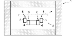
以下、図1および図2を参照して本発明の搬送方法の1実施形態について説明する。図1には本発明の搬送方法を実施する搬送装置(2)を備えた連続炉(1)が示されている。
【0012】
ここで、搬送装置(2)は、左右に間隔をおいて設けられた一対の移動ビーム(3)と、移動ビーム(3)間に左右に間隔をおいて設けられた一対の固定ビーム(4)とを備えている。
【0013】
移動ビーム(3)の間隔および固定ビーム(4)の間隔は被処理物(P)の幅より小さく、被処理物(P)を載せることができるようになっている。移動ビーム(3)は図示しない駆動装置によって駆動され、固定ビーム(4)より上の上昇位置および固定ビーム(4)より下の下降位置の間を上下に移動し、かつ前進位置と後退位置との間を前後に移動するものである。
【0014】
移動ビーム(3)上および固定ビーム(4)上にはそれぞれ多数の被処理物支持用垂直ピン(5)(6)が配されている。
【0015】
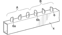
図2には固定ビーム(4)の要部が示されている。同図に示したように垂直ピン(6)の上面は傾斜している。そして、後から3つの垂直ピン(6)が組をなし、支持部(A)を形成し、次の3つの垂直ピン(6)が組をなし、支持部(A)より1つ前方の支持部(B)を形成する。垂直ピン(6)は、対応するピン(6)の上面の向きが異なるようにランダムに配されている。例えば、両支持部(A)(B)の垂直ピン(6a)(6b)が対応するものであるが、図2に示すように両ピン(6a)(6b)の上面の向きは異なっている。
【0016】
上記のように対応する垂直ピン(6)の向きが異なっているので、例えば、支持部(A)に被処理物(P)がある場合と、支持部(A)の1つ前方の支持部(B)に被処理物(P)がある場合とにおいて、被処理物(P)後端部を支持する支持用垂直ピン(6a)(6b)の被処理物接触部は、支持部(A)と1つ前方の支持部(B)とで異なることになる。このように、支持部(A)(B)ごとに被処理物(P)と対応する垂直ピン(6)との接触部分が異なる。
【0017】
詳細な図示は省略したが移動ビーム(3)においてもピン(5)の上面は傾斜し、対応するピン(5)の上面の向きが異なるようにピン(5)が配置されているので搬送時に被処理物(P)の同じ場所が垂直ピン(5)(6)に接触することを避けることができ、被処理物(P)が搬送時に傷つくことがない。
【0018】
なお、移動ビーム(3)は以下のようにして被処理物(P)を前方に搬送する。
【0019】
移動ビーム(3)は、まず後退位置かつ上昇位置にある初期状態をとる。この状態の移動ビーム(3)に被処理物(P)が載せられる。被処理物(P)が載せられた移動ビーム(3)は前進位置まで前進して停止する。ついで移動ビーム(3)は下降する。移動ビーム(3)が固定ビーム(4)より下方の下降位置まで下降し、被処理物(P)が固定ビーム(4)に載せ替えられると、移動ビーム(3)は後退位置まで後退する。後退位置まで後退した移動ビーム(3)は、上昇位置まで上昇し初期状態を取る。この際、固定ビーム(4)上の被処理物(P)は移動ビーム(3)に載せ替えられて持ち上げられる。上記のような動作が繰り返されて被処理物(P)は前方へと搬送される。
【0020】
なお、上記搬送装置は、一方のビーム(4)が上下および前後に移動し、他方のビーム(5)が固定されたものであるが、本発明の搬送装置はこれに限られず、両方のビームが交互に移動して被処理物(P)が搬送されるものや、一方のビームが上下に移動し、他方のビームが前後に移動して被処理物(P)が搬送されるものも含まれる。
【図面の簡単な説明】
【図1】本発明の搬送装置が適用された連続熱処理装置の縦断面図である。
【図2】本発明の搬送装置の要部の斜視図である。
【符号の説明】
(3)(4) ビーム
(5)(6) 被処理物支持用垂直ピン
(A)(B) 被処理物支持部
(P) 被処理物[0001]
BACKGROUND OF THE INVENTION
The present invention relates to a transfer device used in a continuous heat treatment apparatus such as a furnace. In particular, the present invention relates to a transfer device for a processing apparatus such as a furnace used in a clean room or the like for processing a plate-shaped workpiece such as a semiconductor substrate, a glass substrate such as an LCD panel or a plasma display panel, or a printed substrate.
[0002]
[Prior art]
A transfer device for a processing apparatus such as a furnace used in a clean room or the like is required to generate less dust. There is a walking beam type conveying apparatus as one of the conveying apparatuses that satisfy such requirements.
[0003]
The walking beam type conveying apparatus includes a pair of movable beams provided in the left-right direction and extending in the front-rear direction, and a pair of fixed beams spaced in the left-right direction between the movable beams. To transport the workpiece.
[0004]
First, a beam at a position lower than the fixed beam moves upward to lift the object to be processed on the fixed beam. The moving beam then moves forward. Then, the moving beam moves downward and the object to be processed is placed on the fixed beam. After this, the moving beam moves backward.
[0005]
The above-described series of operations is repeated, and the object to be processed is transferred onto the fixed beam forward and conveyed.
[0006]
[Problems to be solved by the invention]
By the way, in the above-described conventional transfer apparatus, there are some in which the workpiece supporting vertical pins are arranged in series on the moving beam and the fixed beam, and the workpiece is supported by the beam supporting vertical pins. In that case, since the vertical pin contact portion for supporting the object to be processed is always the same, there is a problem that the vertical pin contact portion for supporting the object to be processed may be damaged.
[0007]
An object of the present invention is to solve the above-described problems, and an object of the present invention is to provide a transport device that does not damage an object to be processed.
[0008]
[Means for Solving the Problems and Effects of the Invention]
In order to solve the above problems, the transport device of the present invention is
In the walking beam type conveying apparatus provided with at least a pair of beams,
A large number of workpiece support vertical pins are provided in series on each beam, and the upper surface of the vertical pin is inclined and the upper surface of the corresponding vertical pin of the workpiece support portion is oriented differently. It is characterized by being.
[0009]
According to this transport device
For each workpiece support part, the vertical pin comes into contact with a different part of the workpiece being transported, and the workpiece is not damaged.
[0010]
Further, all the vertical pins can have the same shape, and the orientation of these upper surfaces is simply changed and arranged on the beam, so that the conveying device does not become expensive.
[0011]
DETAILED DESCRIPTION OF THE INVENTION
Hereinafter, an embodiment of the transport method of the present invention will be described with reference to FIGS. 1 and 2. FIG. 1 shows a continuous furnace (1) equipped with a transfer device (2) for carrying out the transfer method of the present invention.
[0012]
Here, the transfer device (2) includes a pair of moving beams (3) spaced apart from each other on the left and right, and a pair of fixed beams (4) spaced apart from each other between the moving beams (3). ).
[0013]
The interval between the moving beam (3) and the interval between the fixed beams (4) is smaller than the width of the workpiece (P) so that the workpiece (P) can be placed thereon. The moving beam (3) is driven by a driving device (not shown) and moves up and down between an ascending position above the fixed beam (4) and a descending position below the fixed beam (4). It moves between the front and back.
[0014]
A large number of vertical pins (5) and (6) for supporting an object to be processed are disposed on the moving beam (3) and the fixed beam (4), respectively.
[0015]
FIG. 2 shows the main part of the fixed beam (4). As shown in the figure, the upper surface of the vertical pin (6) is inclined. After that, the three vertical pins (6) form a set and form a support part (A), and the next three vertical pins (6) form a set and support one front from the support part (A). Part (B) is formed. The vertical pins (6) are randomly arranged so that the directions of the upper surfaces of the corresponding pins (6) are different. For example, the vertical pins (6a) and (6b) of the support portions (A) and (B) correspond to each other, but the orientations of the upper surfaces of the pins (6a) and (6b) are different as shown in FIG. .
[0016]
Since the direction of the corresponding vertical pin (6) is different as described above, for example, when the workpiece (P) is present in the support portion (A) and the support portion one front of the support portion (A). In the case where the workpiece (P) is present in (B), the workpiece contact portion of the supporting vertical pin (6a) (6b) that supports the rear end of the workpiece (P) is the support portion (A ) And the one front support part (B). Thus, the contact portion between the workpiece (P) and the corresponding vertical pin (6) is different for each of the support portions (A) and (B).
[0017]
Although detailed illustration is omitted, even in the moving beam (3), the upper surface of the pin (5) is inclined, and the pin (5) is arranged so that the direction of the upper surface of the corresponding pin (5) is different. The same place of the workpiece (P) can be prevented from coming into contact with the vertical pins (5) and (6), and the workpiece (P) is not damaged during transportation.
[0018]
The moving beam (3) conveys the workpiece (P) forward as follows.
[0019]
The moving beam (3) first takes an initial state in the retracted position and the raised position. The workpiece (P) is placed on the moving beam (3) in this state. The moving beam (3) on which the workpiece (P) is placed advances to the advance position and stops. The moving beam (3) then descends. When the moving beam (3) is lowered to a lower position below the fixed beam (4) and the workpiece (P) is transferred to the fixed beam (4), the moving beam (3) is moved back to the retracted position. The moving beam (3) retracted to the retracted position rises to the ascending position and takes an initial state. At this time, the workpiece (P) on the fixed beam (4) is lifted by being transferred to the moving beam (3). The operation as described above is repeated and the workpiece (P) is conveyed forward.
[0020]
Note that the transport device is one in which one beam (4) moves up and down and back and forth, and the other beam (5) is fixed, but the transport device of the present invention is not limited to this, both beams , The workpiece (P) is transported by moving alternately, and the workpiece (P) is transported by moving one beam up and down and the other beam moving back and forth. It is.
[Brief description of the drawings]
FIG. 1 is a longitudinal sectional view of a continuous heat treatment apparatus to which a transfer apparatus of the present invention is applied.
FIG. 2 is a perspective view of a main part of a transport apparatus according to the present invention.
[Explanation of symbols]
(3) (4) Beam
(5) (6) Vertical pin for supporting workpiece
(A) (B) Workpiece support part
(P) Workpiece
Claims (1)
各ビーム上に多数の被処理物支持用垂直ピンが直列に設けられ、
垂直ピンの上面が傾斜しているとともに被処理物支持部の対応する垂直ピンの上面の向きが異なるように配されていることを特徴とするウォーキングビーム式搬送装置。In the walking beam type conveying apparatus provided with at least a pair of beams,
A number of workpiece support vertical pins are provided in series on each beam,
A walking beam type conveying apparatus characterized in that the upper surface of the vertical pin is inclined and the direction of the upper surface of the corresponding vertical pin of the workpiece support portion is different.
Priority Applications (1)
| Application Number | Priority Date | Filing Date | Title |
|---|---|---|---|
| JP2001053824A JP4635350B2 (en) | 2001-02-28 | 2001-02-28 | Transport device |
Applications Claiming Priority (1)
| Application Number | Priority Date | Filing Date | Title |
|---|---|---|---|
| JP2001053824A JP4635350B2 (en) | 2001-02-28 | 2001-02-28 | Transport device |
Publications (2)
| Publication Number | Publication Date |
|---|---|
| JP2002255329A JP2002255329A (en) | 2002-09-11 |
| JP4635350B2 true JP4635350B2 (en) | 2011-02-23 |
Family
ID=18914249
Family Applications (1)
| Application Number | Title | Priority Date | Filing Date |
|---|---|---|---|
| JP2001053824A Expired - Lifetime JP4635350B2 (en) | 2001-02-28 | 2001-02-28 | Transport device |
Country Status (1)
| Country | Link |
|---|---|
| JP (1) | JP4635350B2 (en) |
Families Citing this family (4)
| Publication number | Priority date | Publication date | Assignee | Title |
|---|---|---|---|---|
| JP4515117B2 (en) * | 2003-03-06 | 2010-07-28 | 日本碍子株式会社 | Conveying mechanism using wire, heat treatment furnace and heat treatment method using the same |
| JP2004286425A (en) * | 2003-03-06 | 2004-10-14 | Ngk Insulators Ltd | Carrying mechanism using wire material, heat treatment furnace and heat treatment method using the mechanism |
| JP3917994B2 (en) * | 2004-08-24 | 2007-05-23 | 株式会社石井表記 | Coating film drying oven |
| JP5022855B2 (en) * | 2007-10-05 | 2012-09-12 | 古河機械金属株式会社 | Lift pin mechanism, heat treatment device, vacuum drying device |
Family Cites Families (3)
| Publication number | Priority date | Publication date | Assignee | Title |
|---|---|---|---|---|
| JPS5370013A (en) * | 1976-12-02 | 1978-06-22 | Daido Steel Co Ltd | Walking beam type heating furnace |
| JPH01285517A (en) * | 1988-05-12 | 1989-11-16 | Tokyo Electron Ltd | Conveyer device |
| JPH02108921U (en) * | 1989-02-18 | 1990-08-30 |
-
2001
- 2001-02-28 JP JP2001053824A patent/JP4635350B2/en not_active Expired - Lifetime
Also Published As
| Publication number | Publication date |
|---|---|
| JP2002255329A (en) | 2002-09-11 |
Similar Documents
| Publication | Publication Date | Title |
|---|---|---|
| US5823736A (en) | Substrate processing device and method for substrate from the substrate processing device | |
| JP4633161B2 (en) | Substrate transfer device | |
| JP6659682B2 (en) | Printing equipment | |
| JP5152469B2 (en) | Substrate transfer device | |
| JP4635350B2 (en) | Transport device | |
| JP2005126243A (en) | Substrate elevator and substrate lifting system | |
| JP2006008396A (en) | Plate member conveying apparatus and conveying method, flat panel display manufacturing apparatus and manufacturing method | |
| JP3705699B2 (en) | Thin plate holding and conveying method | |
| JP2005064431A (en) | Substrate transport apparatus and substrate transport method | |
| JP4133489B2 (en) | Substrate standby device and substrate processing apparatus having the same | |
| KR100708216B1 (en) | Substrate loading device | |
| JP3853093B2 (en) | Automatic cleaning device transport mechanism | |
| JPH0545489B2 (en) | ||
| JP3855119B2 (en) | Transport device | |
| JP4457480B2 (en) | Electronic component mounting method | |
| JP5110078B2 (en) | Thin plate conveying method and thin plate processing equipment | |
| JP4922495B2 (en) | Transport device | |
| KR100619222B1 (en) | Glass Upright Feeder | |
| JP3366870B2 (en) | Frit seal device, transfer device and frit seal method | |
| JPS6328599Y2 (en) | ||
| JP3628865B2 (en) | Substrate processing equipment | |
| KR20060075108A (en) | Film Scribing Device for Glass Substrate | |
| KR200319194Y1 (en) | Buffer apparatus for glass with conveyer | |
| KR100551471B1 (en) | Board loading device | |
| JP3486761B2 (en) | Continuous heat treatment equipment |
Legal Events
| Date | Code | Title | Description |
|---|---|---|---|
| A621 | Written request for application examination |
Free format text: JAPANESE INTERMEDIATE CODE: A621 Effective date: 20080118 |
|
| A977 | Report on retrieval |
Free format text: JAPANESE INTERMEDIATE CODE: A971007 Effective date: 20100909 |
|
| TRDD | Decision of grant or rejection written | ||
| A01 | Written decision to grant a patent or to grant a registration (utility model) |
Free format text: JAPANESE INTERMEDIATE CODE: A01 Effective date: 20101012 |
|
| A01 | Written decision to grant a patent or to grant a registration (utility model) |
Free format text: JAPANESE INTERMEDIATE CODE: A01 |
|
| A61 | First payment of annual fees (during grant procedure) |
Free format text: JAPANESE INTERMEDIATE CODE: A61 Effective date: 20101108 |
|
| FPAY | Renewal fee payment (event date is renewal date of database) |
Free format text: PAYMENT UNTIL: 20131203 Year of fee payment: 3 |
|
| R150 | Certificate of patent or registration of utility model |
Ref document number: 4635350 Country of ref document: JP Free format text: JAPANESE INTERMEDIATE CODE: R150 Free format text: JAPANESE INTERMEDIATE CODE: R150 |
|
| R250 | Receipt of annual fees |
Free format text: JAPANESE INTERMEDIATE CODE: R250 |
|
| R250 | Receipt of annual fees |
Free format text: JAPANESE INTERMEDIATE CODE: R250 |
|
| R250 | Receipt of annual fees |
Free format text: JAPANESE INTERMEDIATE CODE: R250 |
|
| R250 | Receipt of annual fees |
Free format text: JAPANESE INTERMEDIATE CODE: R250 |
|
| R250 | Receipt of annual fees |
Free format text: JAPANESE INTERMEDIATE CODE: R250 |
|
| R250 | Receipt of annual fees |
Free format text: JAPANESE INTERMEDIATE CODE: R250 |
|
| R250 | Receipt of annual fees |
Free format text: JAPANESE INTERMEDIATE CODE: R250 |
|
| R250 | Receipt of annual fees |
Free format text: JAPANESE INTERMEDIATE CODE: R250 |
|
| EXPY | Cancellation because of completion of term |