JP4438726B2 - 火花点火式エンジンの燃焼室構造 - Google Patents
火花点火式エンジンの燃焼室構造 Download PDFInfo
- Publication number
- JP4438726B2 JP4438726B2 JP2005273525A JP2005273525A JP4438726B2 JP 4438726 B2 JP4438726 B2 JP 4438726B2 JP 2005273525 A JP2005273525 A JP 2005273525A JP 2005273525 A JP2005273525 A JP 2005273525A JP 4438726 B2 JP4438726 B2 JP 4438726B2
- Authority
- JP
- Japan
- Prior art keywords
- combustion
- combustion chamber
- ceiling wall
- spark plug
- periphery
- Prior art date
- Legal status (The legal status is an assumption and is not a legal conclusion. Google has not performed a legal analysis and makes no representation as to the accuracy of the status listed.)
- Expired - Fee Related
Links
- 238000002485 combustion reaction Methods 0.000 title claims description 300
- 230000002093 peripheral effect Effects 0.000 claims description 12
- 230000006835 compression Effects 0.000 description 16
- 238000007906 compression Methods 0.000 description 16
- 239000000446 fuel Substances 0.000 description 16
- 238000005474 detonation Methods 0.000 description 10
- 230000005484 gravity Effects 0.000 description 10
- 230000009471 action Effects 0.000 description 8
- 230000020169 heat generation Effects 0.000 description 8
- 230000002159 abnormal effect Effects 0.000 description 5
- 230000000694 effects Effects 0.000 description 5
- 239000000203 mixture Substances 0.000 description 5
- 230000003111 delayed effect Effects 0.000 description 4
- 229940054107 isochron Drugs 0.000 description 4
- MOYKHGMNXAOIAT-JGWLITMVSA-N isosorbide dinitrate Chemical compound [O-][N+](=O)O[C@H]1CO[C@@H]2[C@H](O[N+](=O)[O-])CO[C@@H]21 MOYKHGMNXAOIAT-JGWLITMVSA-N 0.000 description 4
- 238000004904 shortening Methods 0.000 description 4
- 230000007704 transition Effects 0.000 description 4
- 230000002411 adverse Effects 0.000 description 3
- 238000010586 diagram Methods 0.000 description 3
- 230000008901 benefit Effects 0.000 description 2
- 230000002542 deteriorative effect Effects 0.000 description 2
- 230000013011 mating Effects 0.000 description 2
- 230000007423 decrease Effects 0.000 description 1
- 230000007613 environmental effect Effects 0.000 description 1
- 238000004519 manufacturing process Methods 0.000 description 1
- 238000000034 method Methods 0.000 description 1
- 238000007790 scraping Methods 0.000 description 1
- 230000002195 synergetic effect Effects 0.000 description 1
- 230000009466 transformation Effects 0.000 description 1
- 238000010792 warming Methods 0.000 description 1
Images


Classifications
-
- Y—GENERAL TAGGING OF NEW TECHNOLOGICAL DEVELOPMENTS; GENERAL TAGGING OF CROSS-SECTIONAL TECHNOLOGIES SPANNING OVER SEVERAL SECTIONS OF THE IPC; TECHNICAL SUBJECTS COVERED BY FORMER USPC CROSS-REFERENCE ART COLLECTIONS [XRACs] AND DIGESTS
- Y02—TECHNOLOGIES OR APPLICATIONS FOR MITIGATION OR ADAPTATION AGAINST CLIMATE CHANGE
- Y02T—CLIMATE CHANGE MITIGATION TECHNOLOGIES RELATED TO TRANSPORTATION
- Y02T10/00—Road transport of goods or passengers
- Y02T10/10—Internal combustion engine [ICE] based vehicles
- Y02T10/12—Improving ICE efficiencies
Landscapes
- Ignition Installations For Internal Combustion Engines (AREA)
- Combustion Methods Of Internal-Combustion Engines (AREA)
Description
グ性能を高めた分だけ圧縮比を増大させる、つまり耐ノッキング性能を悪化させることなく圧縮比を高めることができる。本願発明者は、本発明の燃焼室構造によって、耐ノッキング性能を悪化させることなく圧縮比を従来比で0.5以上高めることができることを確認している。また、本発明によれば、ピストン冠部に凹凸を設けるという簡単な構造で第1燃焼空間、小間隙部および第2燃焼空間を形成することができる。さらに、比較的大きな吸排気バルブ径を確保しつつ、燃焼室容積を小さくすることができるというペントルーフ型燃焼室の特徴を利用して、より容易に高圧縮比化を図ることができる。また、上記小間隙部のうち排気側は吸気側に対してさらに間隙が小さい最小間隙部となるように、上記凸部において排気側が吸気側に対して高く形成されているので、第1燃焼空間から第2燃焼空間への火炎伝播が、全体的により均等となり円滑な燃焼を図ることができる。
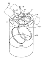
5 小間隙部
6 凸部
7 中央側凹部(凹部)
8 周縁側凹部(凹部)
9 凸部頂面
10 シリンダヘッド
11 天井壁(シリンダヘッド下面)
11a 吸気側天井壁
11b 排気側天井壁
12 シリンダボア
13 ピストン
13a ピストン冠部
14 燃焼室
14a 第1燃焼空間
14b 第2燃焼空間
15 第1点火プラグ
15a 第2点火プラグ
16 吸気側間隙部
21 吸気ポート(タンブル生成ポート)
22 排気ポート
30 タンブル
Claims (3)
- シリンダヘッド下面とピストン頂面との間に形成され、上記シリンダヘッド下面を天井壁とする燃焼室と、
上記天井壁の、シリンダボア軸線を挟んだ一方側に開口する2個の吸気ポートと、
同他方側に開口する少なくとも1個の排気ポートと、
上記天井壁の、シリンダボア径方向中央部から上記燃焼室内に先端が臨設された第1点火プラグとを含む火花点火式エンジンの燃焼室構造であって、
上記燃焼室は、吸気側天井壁と排気側天井壁とが屋根形をなすペントルーフ型であり、
上記2個の吸気ポート開口部の間であってシリンダボア周縁部における上記天井壁から上記燃焼室内に先端が臨む第2点火プラグが設けられ、
ピストンが上死点にある状態で、上記燃焼室内空間の主要部が、上記第1点火プラグ周辺から上記第2点火プラグ周辺にかけて連続する第1燃焼空間と、シリンダボア周縁部の第2燃焼空間とによって形成され、
上記第1点火プラグ周辺から排気側のシリンダボア周縁にかけての途中位置に、上記第1燃焼空間と上記第2燃焼空間とを連通するとともに、上記天井壁と上記ピストン頂面との間隙が周囲よりも狭められた小間隙部が形成されており、
該小間隙部は、ピストンの冠部に設けられた凸部の頂面と上記天井壁との間に形成され、該凸部は、平面視で吸気側の第2点火プラグ下方部位が切り欠かれた略円環状をなして上方に突出し、
該凸部の内側および外側においてそれぞれ、該凸部に対して相対的に没入した凹部と上記天井壁との間に上記第1燃焼空間および上記第2燃焼空間が形成され、該第2燃焼空間は上記凸部の外周に沿って略環状に形成されているとともに、
上記小間隙部のうち排気側は吸気側に対してさらに間隙が小さい最小間隙部となるように、上記凸部において排気側が吸気側に対して高く形成されていることを特徴とする火花点火式エンジンの燃焼室構造。 - 上記2個の吸気ポートは、タンブル生成ポートであることを特徴とする請求項1記載の火花点火式エンジンの燃焼室構造。
- 上記小間隙部は、上記シリンダボア径方向における、上記第1点火プラグから上記シリンダボア周縁との中間点よりも上記シリンダボア周縁寄りに形成されていることを特徴とする請求項1または2記載の火花点火式エンジンの燃焼室構造。
Priority Applications (1)
| Application Number | Priority Date | Filing Date | Title |
|---|---|---|---|
| JP2005273525A JP4438726B2 (ja) | 2005-09-21 | 2005-09-21 | 火花点火式エンジンの燃焼室構造 |
Applications Claiming Priority (1)
| Application Number | Priority Date | Filing Date | Title |
|---|---|---|---|
| JP2005273525A JP4438726B2 (ja) | 2005-09-21 | 2005-09-21 | 火花点火式エンジンの燃焼室構造 |
Publications (2)
| Publication Number | Publication Date |
|---|---|
| JP2007085220A JP2007085220A (ja) | 2007-04-05 |
| JP4438726B2 true JP4438726B2 (ja) | 2010-03-24 |
Family
ID=37972456
Family Applications (1)
| Application Number | Title | Priority Date | Filing Date |
|---|---|---|---|
| JP2005273525A Expired - Fee Related JP4438726B2 (ja) | 2005-09-21 | 2005-09-21 | 火花点火式エンジンの燃焼室構造 |
Country Status (1)
| Country | Link |
|---|---|
| JP (1) | JP4438726B2 (ja) |
Families Citing this family (4)
| Publication number | Priority date | Publication date | Assignee | Title |
|---|---|---|---|---|
| JP5239720B2 (ja) * | 2008-10-08 | 2013-07-17 | 日産自動車株式会社 | 火花点火内燃機関 |
| US8151747B2 (en) * | 2009-04-07 | 2012-04-10 | Scuderi Group, Llc | Crescent-shaped recess in piston of a split-cycle engine |
| DE102016007279A1 (de) * | 2016-06-15 | 2017-12-21 | Audi Ag | Kolben für eine Brennkraftmaschine sowie entsprechende Brennkraftmaschine |
| CN118912536B (zh) * | 2024-07-19 | 2025-11-21 | 浙江大学 | 一种高空点火机理研究的环形燃烧室装置 |
-
2005
- 2005-09-21 JP JP2005273525A patent/JP4438726B2/ja not_active Expired - Fee Related
Also Published As
| Publication number | Publication date |
|---|---|
| JP2007085220A (ja) | 2007-04-05 |
Similar Documents
| Publication | Publication Date | Title |
|---|---|---|
| EP1764491B1 (en) | Combustion chamber structure for spark-ignition engine | |
| JP7388224B2 (ja) | プレチャンバを備える内燃機関 | |
| JP4280925B2 (ja) | 内燃機関の燃焼室構造 | |
| JP2009041397A (ja) | 複数点火エンジンの燃焼室構造 | |
| JP4702409B2 (ja) | 火花点火式内燃機関 | |
| JP4428325B2 (ja) | 火花点火式エンジンの燃焼室構造 | |
| JP3906963B2 (ja) | 内燃機関の燃焼室構造 | |
| JP4438726B2 (ja) | 火花点火式エンジンの燃焼室構造 | |
| JP6006276B2 (ja) | 内燃機関 | |
| JP4432867B2 (ja) | 火花点火式エンジン | |
| US6701883B2 (en) | Cylinder head for use on a spark-ignition internal combustion engine and such spark-ignition internal combustion engine | |
| JPS5838610B2 (ja) | 内燃機関 | |
| JP4618067B2 (ja) | 火花点火式エンジン | |
| JP4442542B2 (ja) | 往復動ピストン型エンジン | |
| JP3982482B2 (ja) | 筒内直接噴射式内燃機関の燃焼室構造 | |
| JP2006152904A (ja) | 内燃機関の燃焼室構造 | |
| JP2022083622A (ja) | エンジンの燃焼室構造 | |
| JP4257520B2 (ja) | 筒内噴射型内燃機関 | |
| JP7610450B2 (ja) | エンジンシステム | |
| JP2007085221A (ja) | 火花点火式直噴エンジンの燃焼室構造 | |
| JP2016113990A (ja) | 内燃機関 | |
| JPH11182249A (ja) | 直噴火花点火式内燃機関 | |
| JP3852273B2 (ja) | 内燃機関の燃焼室 | |
| JP4216944B2 (ja) | 内燃機関の燃焼室構造 | |
| JP3966619B2 (ja) | 内燃機関の燃焼室構造 |
Legal Events
| Date | Code | Title | Description |
|---|---|---|---|
| A621 | Written request for application examination |
Free format text: JAPANESE INTERMEDIATE CODE: A621 Effective date: 20080303 |
|
| A977 | Report on retrieval |
Free format text: JAPANESE INTERMEDIATE CODE: A971007 Effective date: 20090827 |
|
| A131 | Notification of reasons for refusal |
Free format text: JAPANESE INTERMEDIATE CODE: A131 Effective date: 20090908 |
|
| A521 | Written amendment |
Free format text: JAPANESE INTERMEDIATE CODE: A523 Effective date: 20091109 |
|
| TRDD | Decision of grant or rejection written | ||
| A01 | Written decision to grant a patent or to grant a registration (utility model) |
Free format text: JAPANESE INTERMEDIATE CODE: A01 Effective date: 20091215 |
|
| A01 | Written decision to grant a patent or to grant a registration (utility model) |
Free format text: JAPANESE INTERMEDIATE CODE: A01 |
|
| A61 | First payment of annual fees (during grant procedure) |
Free format text: JAPANESE INTERMEDIATE CODE: A61 Effective date: 20091228 |
|
| FPAY | Renewal fee payment (event date is renewal date of database) |
Free format text: PAYMENT UNTIL: 20130115 Year of fee payment: 3 |
|
| R150 | Certificate of patent or registration of utility model |
Ref document number: 4438726 Country of ref document: JP Free format text: JAPANESE INTERMEDIATE CODE: R150 Free format text: JAPANESE INTERMEDIATE CODE: R150 |
|
| FPAY | Renewal fee payment (event date is renewal date of database) |
Free format text: PAYMENT UNTIL: 20140115 Year of fee payment: 4 |
|
| LAPS | Cancellation because of no payment of annual fees |