JP4437487B2 - 捩り管形熱交換器及びヒートポンプ式給湯機 - Google Patents
捩り管形熱交換器及びヒートポンプ式給湯機 Download PDFInfo
- Publication number
- JP4437487B2 JP4437487B2 JP2006279559A JP2006279559A JP4437487B2 JP 4437487 B2 JP4437487 B2 JP 4437487B2 JP 2006279559 A JP2006279559 A JP 2006279559A JP 2006279559 A JP2006279559 A JP 2006279559A JP 4437487 B2 JP4437487 B2 JP 4437487B2
- Authority
- JP
- Japan
- Prior art keywords
- heat exchanger
- pipe
- twisted
- tube heat
- refrigerant
- Prior art date
- Legal status (The legal status is an assumption and is not a legal conclusion. Google has not performed a legal analysis and makes no representation as to the accuracy of the status listed.)
- Expired - Fee Related
Links
Images


Landscapes
- Heat-Exchange Devices With Radiators And Conduit Assemblies (AREA)
Description
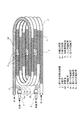
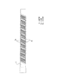
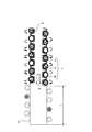
図1乃至図7は実施の形態1を示す図で、図1は給湯室外機50の分解斜視図、図2は冷媒回路と水回路図、図3は捩り管形熱交換器1を示す斜視図、図4は捩り形状の水配管2を示す平面図、図5は捩り管形熱交換器1入口部の冷媒配管3の巻き付け状態を示す拡大図、図6は捩り管形熱交換器1出口部の冷媒配管3巻き付け状態を示す拡大図、図7は炭酸カルシウム析出加速試験の結果を示す図である。
本実施の形態の捩り管形熱交換器1は水配管2が長円渦巻状に形成されていることを特徴とする。
図8は実施の形態2を示す図で、捩り管形熱交換器1の構成を示す平面図である。捩り管形熱交換器1の捩り形状の水配管2は図4、捩り管形熱交換器1入口部の冷媒配管3の巻き付け状態は図5、捩り管形熱交換器1出口部の冷媒配管3の巻き付け状態は図6と同じである。
Claims (10)
- 外周に複数条の山谷底部を各条毎に連続して螺旋状に設けた水配管と、
この水配管外周に螺旋状に巻き付けた複数の冷媒配管とを備え、
前記水配管は、1本の平滑管に対して、捩り加工した部分と捩り加工しない部分とを有し、
前記捩り加工した部分は、前記山谷底部により螺旋形状を有し、前記捩り加工しない部分の内径より小さい内径を有し、
前記捩り加工しない部分は、前記水配管出口側に設けられており、前記水配管出口側から所定の長さの捩り加工しない部分を螺旋形状のない素管部とし、
複数の冷媒配管は、前記山谷底部の形状に沿って螺旋状に巻き付けられ、前記山谷底部の形状に沿って巻き付けられた複数の冷媒配管が、連続して、素管部の外周に螺旋状に巻き付けられたことを特徴とする捩り管形熱交換器。 - 前記捩り加工した部分の前記山谷底部を形成する谷底部の内面が、前記捩り加工しない部分の内面より流路中央側に形成されたことを特徴とする請求項1に記載の捩り管形熱交換器。
- 前記水配管は、捩り加工した部分と捩り加工しない部分との間に接続箇所を設けることなく、捩り加工した部分から捩り加工しない部分に向かって流路断面積を拡大したことを特徴とする請求項1又は2に記載の捩り管形熱交換器。
- 前記水配管の素管部は、前記平滑管に対する捩り加工時に、捩り加工しない部分を設定することにより形成された流路拡大部であることを特徴とする請求項1乃至3のいずれかに記載の捩り管形熱交換器。
- 前記複数の冷媒配管は、前記水配管の素管部を流れる水の温度が、複数の冷媒配管との熱交換によって、スケールが析出する温度から所定の温度になるまでの範囲で、前記素管部に螺旋状に巻き付けられたことを特徴とす請求項1乃至4いずれかに記載の捩り管形熱交換器。
- 前記水配管全長に対する前記素管部の長さの比率を2〜10%とすることを特徴とする請求項1乃至5のいずれかに記載の捩り管形熱交換器。
- 前記素管部に少なくとも1箇所以上の曲げ部を設けたことを特徴とする請求項1乃至6のいずれかに記載の捩り管形熱交換器。
- 上記捩り管形熱交換器は、長円コイル状に巻いた構成又は長円渦巻状に巻いた構成としたことを特徴とする請求項1乃至7のいずれかに記載の捩り管形熱交換器。
- 上記捩り管形熱交換器は、前記水配管と前記冷媒配管とに水及び冷媒を対向流となるように流す構成とすることを特徴とする請求項1乃至8のいずれかに記載の捩り管形熱交換器。
- 請求項1乃至9のいずれかに記載の捩り管形熱交換器を用いたことを特徴とするヒートポンプ式給湯機。
Priority Applications (1)
| Application Number | Priority Date | Filing Date | Title |
|---|---|---|---|
| JP2006279559A JP4437487B2 (ja) | 2006-10-13 | 2006-10-13 | 捩り管形熱交換器及びヒートポンプ式給湯機 |
Applications Claiming Priority (1)
| Application Number | Priority Date | Filing Date | Title |
|---|---|---|---|
| JP2006279559A JP4437487B2 (ja) | 2006-10-13 | 2006-10-13 | 捩り管形熱交換器及びヒートポンプ式給湯機 |
Publications (3)
| Publication Number | Publication Date |
|---|---|
| JP2008096043A JP2008096043A (ja) | 2008-04-24 |
| JP2008096043A5 JP2008096043A5 (ja) | 2008-09-04 |
| JP4437487B2 true JP4437487B2 (ja) | 2010-03-24 |
Family
ID=39379069
Family Applications (1)
| Application Number | Title | Priority Date | Filing Date |
|---|---|---|---|
| JP2006279559A Expired - Fee Related JP4437487B2 (ja) | 2006-10-13 | 2006-10-13 | 捩り管形熱交換器及びヒートポンプ式給湯機 |
Country Status (1)
| Country | Link |
|---|---|
| JP (1) | JP4437487B2 (ja) |
Cited By (1)
| Publication number | Priority date | Publication date | Assignee | Title |
|---|---|---|---|---|
| CN104236339A (zh) * | 2013-06-14 | 2014-12-24 | 三菱电机株式会社 | 扭管式换热器以及扭管式换热器的制造方法 |
Families Citing this family (5)
| Publication number | Priority date | Publication date | Assignee | Title |
|---|---|---|---|---|
| JP5513738B2 (ja) * | 2008-12-24 | 2014-06-04 | 東芝キヤリア株式会社 | 熱交換器およびヒートポンプ式給湯機 |
| JP5378782B2 (ja) * | 2008-12-26 | 2013-12-25 | カルソニックカンセイ株式会社 | 熱交換器 |
| JP5625966B2 (ja) * | 2011-02-03 | 2014-11-19 | 三菱電機株式会社 | ヒートポンプ給湯室外機 |
| JP5656786B2 (ja) * | 2011-09-22 | 2015-01-21 | 三菱電機株式会社 | 異径捩り管形熱交換器の製造方法 |
| CN208765538U (zh) * | 2017-01-18 | 2019-04-19 | 三菱电机株式会社 | 螺旋管式热交换器 |
-
2006
- 2006-10-13 JP JP2006279559A patent/JP4437487B2/ja not_active Expired - Fee Related
Cited By (1)
| Publication number | Priority date | Publication date | Assignee | Title |
|---|---|---|---|---|
| CN104236339A (zh) * | 2013-06-14 | 2014-12-24 | 三菱电机株式会社 | 扭管式换热器以及扭管式换热器的制造方法 |
Also Published As
| Publication number | Publication date |
|---|---|
| JP2008096043A (ja) | 2008-04-24 |
Similar Documents
| Publication | Publication Date | Title |
|---|---|---|
| CN107532870B (zh) | 热交换器和使用其的制冷循环装置 | |
| US20050269069A1 (en) | Heat transfer apparatus with enhanced micro-channel heat transfer tubing | |
| JP2001201275A (ja) | 二重管式熱交換器 | |
| CN101021393A (zh) | 热交换器用传热管以及使用其的热交换器 | |
| JP4211041B2 (ja) | ヒートポンプ給湯機 | |
| JP4449856B2 (ja) | 捩り管形熱交換器 | |
| CN101769656A (zh) | 一种电冰箱用蛇形平行流冷凝器 | |
| JP2002228370A (ja) | 熱交換器 | |
| JP4437487B2 (ja) | 捩り管形熱交換器及びヒートポンプ式給湯機 | |
| JP2003097898A (ja) | 熱交換器 | |
| JP4572662B2 (ja) | 熱交換器 | |
| JP4501446B2 (ja) | 給湯用熱交換器 | |
| JP6573210B2 (ja) | 二重管式熱交換器及びこれを備えたヒートポンプ式熱源機 | |
| JP4736533B2 (ja) | 熱交換器 | |
| JP4224793B2 (ja) | 熱交換器及びその製造方法 | |
| JP2010091266A (ja) | 捩り管形熱交換器 | |
| JP2006162165A (ja) | 熱交換器 | |
| JP4615422B2 (ja) | 伝熱管、給湯用熱交換器およびヒートポンプ給湯器 | |
| JP2005009832A (ja) | 二重管式熱交換器 | |
| JP2003343995A (ja) | 伝熱管 | |
| JP5540683B2 (ja) | 熱交換器及びそれを備えた給湯機 | |
| JPS5864496A (ja) | 二重管式熱交換器 | |
| CN206766313U (zh) | 船用空调器系统及具有其的交通工具 | |
| JP5760105B2 (ja) | 給湯用熱交換器 | |
| JP2007218523A (ja) | 熱交換器 |
Legal Events
| Date | Code | Title | Description |
|---|---|---|---|
| A521 | Request for written amendment filed |
Free format text: JAPANESE INTERMEDIATE CODE: A523 Effective date: 20080723 |
|
| A621 | Written request for application examination |
Free format text: JAPANESE INTERMEDIATE CODE: A621 Effective date: 20080723 |
|
| A977 | Report on retrieval |
Free format text: JAPANESE INTERMEDIATE CODE: A971007 Effective date: 20090918 |
|
| A131 | Notification of reasons for refusal |
Free format text: JAPANESE INTERMEDIATE CODE: A131 Effective date: 20090929 |
|
| A521 | Request for written amendment filed |
Free format text: JAPANESE INTERMEDIATE CODE: A523 Effective date: 20091125 |
|
| TRDD | Decision of grant or rejection written | ||
| A01 | Written decision to grant a patent or to grant a registration (utility model) |
Free format text: JAPANESE INTERMEDIATE CODE: A01 Effective date: 20091222 |
|
| A01 | Written decision to grant a patent or to grant a registration (utility model) |
Free format text: JAPANESE INTERMEDIATE CODE: A01 |
|
| A61 | First payment of annual fees (during grant procedure) |
Free format text: JAPANESE INTERMEDIATE CODE: A61 Effective date: 20091222 |
|
| FPAY | Renewal fee payment (event date is renewal date of database) |
Free format text: PAYMENT UNTIL: 20130115 Year of fee payment: 3 |
|
| R150 | Certificate of patent or registration of utility model |
Ref document number: 4437487 Country of ref document: JP Free format text: JAPANESE INTERMEDIATE CODE: R150 Free format text: JAPANESE INTERMEDIATE CODE: R150 |
|
| FPAY | Renewal fee payment (event date is renewal date of database) |
Free format text: PAYMENT UNTIL: 20130115 Year of fee payment: 3 |
|
| R250 | Receipt of annual fees |
Free format text: JAPANESE INTERMEDIATE CODE: R250 |
|
| R250 | Receipt of annual fees |
Free format text: JAPANESE INTERMEDIATE CODE: R250 |
|
| R250 | Receipt of annual fees |
Free format text: JAPANESE INTERMEDIATE CODE: R250 |
|
| R250 | Receipt of annual fees |
Free format text: JAPANESE INTERMEDIATE CODE: R250 |
|
| R250 | Receipt of annual fees |
Free format text: JAPANESE INTERMEDIATE CODE: R250 |
|
| R250 | Receipt of annual fees |
Free format text: JAPANESE INTERMEDIATE CODE: R250 |
|
| R250 | Receipt of annual fees |
Free format text: JAPANESE INTERMEDIATE CODE: R250 |
|
| R250 | Receipt of annual fees |
Free format text: JAPANESE INTERMEDIATE CODE: R250 |
|
| R250 | Receipt of annual fees |
Free format text: JAPANESE INTERMEDIATE CODE: R250 |
|
| LAPS | Cancellation because of no payment of annual fees |