WO2018134899A1 - 捻り管式熱交換器 - Google Patents
捻り管式熱交換器 Download PDFInfo
- Publication number
- WO2018134899A1 WO2018134899A1 PCT/JP2017/001447 JP2017001447W WO2018134899A1 WO 2018134899 A1 WO2018134899 A1 WO 2018134899A1 JP 2017001447 W JP2017001447 W JP 2017001447W WO 2018134899 A1 WO2018134899 A1 WO 2018134899A1
- Authority
- WO
- WIPO (PCT)
- Prior art keywords
- pipe
- range
- heat exchanger
- insulating material
- heat insulating
- Prior art date
Links
Images


Classifications
-
- F—MECHANICAL ENGINEERING; LIGHTING; HEATING; WEAPONS; BLASTING
- F28—HEAT EXCHANGE IN GENERAL
- F28D—HEAT-EXCHANGE APPARATUS, NOT PROVIDED FOR IN ANOTHER SUBCLASS, IN WHICH THE HEAT-EXCHANGE MEDIA DO NOT COME INTO DIRECT CONTACT
- F28D7/00—Heat-exchange apparatus having stationary tubular conduit assemblies for both heat-exchange media, the media being in contact with different sides of a conduit wall
- F28D7/0008—Heat-exchange apparatus having stationary tubular conduit assemblies for both heat-exchange media, the media being in contact with different sides of a conduit wall the conduits for one medium being in heat conductive contact with the conduits for the other medium
- F28D7/0016—Heat-exchange apparatus having stationary tubular conduit assemblies for both heat-exchange media, the media being in contact with different sides of a conduit wall the conduits for one medium being in heat conductive contact with the conduits for the other medium the conduits for one medium or the conduits for both media being bent
-
- F—MECHANICAL ENGINEERING; LIGHTING; HEATING; WEAPONS; BLASTING
- F28—HEAT EXCHANGE IN GENERAL
- F28F—DETAILS OF HEAT-EXCHANGE AND HEAT-TRANSFER APPARATUS, OF GENERAL APPLICATION
- F28F19/00—Preventing the formation of deposits or corrosion, e.g. by using filters or scrapers
-
- F—MECHANICAL ENGINEERING; LIGHTING; HEATING; WEAPONS; BLASTING
- F28—HEAT EXCHANGE IN GENERAL
- F28D—HEAT-EXCHANGE APPARATUS, NOT PROVIDED FOR IN ANOTHER SUBCLASS, IN WHICH THE HEAT-EXCHANGE MEDIA DO NOT COME INTO DIRECT CONTACT
- F28D7/00—Heat-exchange apparatus having stationary tubular conduit assemblies for both heat-exchange media, the media being in contact with different sides of a conduit wall
- F28D7/02—Heat-exchange apparatus having stationary tubular conduit assemblies for both heat-exchange media, the media being in contact with different sides of a conduit wall the conduits being helically coiled
- F28D7/024—Heat-exchange apparatus having stationary tubular conduit assemblies for both heat-exchange media, the media being in contact with different sides of a conduit wall the conduits being helically coiled the conduits of only one medium being helically coiled tubes, the coils having a cylindrical configuration
-
- F—MECHANICAL ENGINEERING; LIGHTING; HEATING; WEAPONS; BLASTING
- F28—HEAT EXCHANGE IN GENERAL
- F28F—DETAILS OF HEAT-EXCHANGE AND HEAT-TRANSFER APPARATUS, OF GENERAL APPLICATION
- F28F2210/00—Heat exchange conduits
- F28F2210/06—Heat exchange conduits having walls comprising obliquely extending corrugations, e.g. in the form of threads
-
- F—MECHANICAL ENGINEERING; LIGHTING; HEATING; WEAPONS; BLASTING
- F28—HEAT EXCHANGE IN GENERAL
- F28F—DETAILS OF HEAT-EXCHANGE AND HEAT-TRANSFER APPARATUS, OF GENERAL APPLICATION
- F28F2270/00—Thermal insulation; Thermal decoupling
Definitions
- the present invention relates to a twisted tube heat exchanger including a first pipe and a second pipe spirally provided on the outer periphery of the first pipe.
- heat exchange includes a first pipe and a second pipe provided on the outer periphery of the first pipe, and heats a first fluid such as water flowing in the first pipe with a refrigerant flowing in the second pipe.
- a container is known (see, for example, Patent Document 1).
- the second pipe is arranged along the length direction of the first pipe.
- the first pipe and the second pipe are arranged in parallel.
- the heat exchanger of patent document 1 has covered the outer peripheral part of the 1st piping and the 2nd piping with the resin layer, and has made the 2nd piping adhere to the 1st piping.
- This resin layer covering the outer periphery of the first pipe and the second pipe also functions as a heat insulating material. Moreover, this resin layer is provided in the outer peripheral part of a 1st piping and a 2nd piping by an extrusion method.
- a twisted tube heat exchanger has also been proposed as a heat exchanger for heating a first fluid such as water flowing in the first pipe with a refrigerant flowing in the second pipe.
- the twisted tube heat exchanger includes a first pipe having a spiral groove formed on the outer periphery thereof, and a second pipe wound around the groove of the first pipe. That is, the second pipe is spirally provided on the outer periphery of the first pipe.
- the heat exchanger described in Patent Document 1 a resin layer that functions as a heat insulating material is formed by an extrusion method. That is, the heat exchanger described in Patent Document 1 has a configuration in which a heat insulating material is provided in the entire heat exchanger. For this reason, the structure which provides a heat insulating material like patent document 1 had the subject that the material cost of a heat exchanger would increase.
- the twisted pipe heat exchanger has a complicated shape in which the second pipe is spirally provided on the outer periphery of the first pipe. For this reason, it is practically impossible to form a resin layer on the outer peripheral portion of the twisted tube heat exchanger by an extrusion method. For this reason, the conventional twisted tube heat exchanger has a problem that the outer peripheral portion is not provided with a heat insulating layer and the second pipe is corroded.
- both ends of the second pipe are connected to a pipe that supplies the refrigerant to the second pipe and a pipe that causes the refrigerant to flow out of the second pipe, so that the two pipes are not wound around the outer periphery of the first pipe. It has become.
- the middle part of 2nd piping is wound around the outer peripheral part of the middle part of 1st piping.
- the 2nd piping part wound by the outer peripheral part of the 1st piping and the 1st piping are joined by solder etc., for example.
- the range in which the first pipe and the second pipe are joined is referred to as the first range, and is present on the end side of the first pipe with respect to the first range, and the first pipe and the second pipe are joined.
- the range that is not set is referred to as a second range.
- the first fluid flowing into the first pipe first flows in the second range. Thereafter, the first fluid in the first pipe flows into the first range and is heated by the refrigerant flowing in the second pipe. That is, the first fluid flowing through the first piping portion existing in the second range is not yet heated by the refrigerant, and thus has a low temperature. For this reason, the 1st piping part which exists in a 2nd range becomes low temperature from ambient temperature, and it is easy to dew condensation.
- the second range is a range where the first pipe and the second pipe are not joined, and a gap is formed between the first pipe and the second pipe.
- the dew condensation water is bridged.
- the refrigerant coolant higher temperature than the 1st fluid is flowing. That is, the second pipe is at a higher temperature than the first pipe.
- the present invention has been made to solve the above-described problems, and provides a twisted tube heat exchanger that can suppress the corrosion of the second pipe and also can suppress an increase in material cost. With the goal.
- a spiral groove is formed on the outer periphery, and a part of the first pipe through which the first fluid flows and the groove of the first pipe are wound.
- a twist pipe having a second pipe through which a refrigerant for heating the first fluid flows, and a range in which the first pipe and the second pipe are joined is defined as a first range, When a range in which the first pipe and the second pipe are not joined to each other is defined as a second range, the first range and the second range. Wrapped around a part of the range including the boundary with the range so as to cover the outer periphery of the first pipe and the second pipe in the boundary and the outer periphery of the first pipe in the second range. It is the heat exchanger provided with the heat insulating material.
- the twisted tube heat exchanger according to the present invention can be used as a configuration in which the first fluid flows from the second range toward the first range.
- the twisted tube heat exchanger according to the present invention includes an outer peripheral portion of the first pipe and the second pipe at a boundary portion between the first range and the second range, and an outer peripheral portion of the first pipe in the second range.
- a heat insulating material is wound around the cover. That is, in the twisted tube heat exchanger according to the present invention, the condensed water bridged between the first pipe and the second pipe acts as a temperature difference battery, and a heat insulating material is provided at a location where corrosion occurs in the second pipe. It is wrapped around.
- the method of attaching the heat insulating material by winding the heat insulating material is a method in which the heat insulating material can be easily attached even in a twisted tube heat exchanger having a complicated shape.
- the twisted tube heat exchanger according to the present invention can suppress dew condensation water from bridging between the first piping and the second piping, and the location acts as a temperature difference battery to the second piping. The occurrence of corrosion can be suppressed.
- the torsion tube heat exchanger according to the present invention is provided with a heat insulating material only in a part, it is possible to suppress an increase in the material cost of the torsion tube heat exchanger.
- FIG. 1 It is a perspective view which shows the twisted tube type heat exchanger which concerns on embodiment of this invention. It is a principal part enlarged view which shows the heat insulating material attachment range vicinity in the twisted tube of the twisted tube type heat exchanger which concerns on embodiment of this invention, and is a figure which shows the state by which the heat insulating material is not attached. It is a principal part enlarged view which shows the heat insulating material attachment range vicinity in the twisted pipe of the twisted tube type heat exchanger which concerns on embodiment of this invention, and is a figure which shows the state by which the heat insulating material is attached. It is sectional drawing of the heat insulating material attachment range in the twisted tube of the twisted tube type heat exchanger which concerns on embodiment of this invention.
- FIG. 1 is a perspective view showing a twisted tube heat exchanger according to an embodiment of the present invention.
- the twisted tube heat exchanger 100 includes a twisted tube 1. Details of the twisted tube 1 will be described later. As described later, the twisted tube 1 includes a first pipe 10 through which a first fluid such as water flows, a second pipe 20 through which a refrigerant for heating the first fluid flows, (See FIGS. 2 and 3 to be described later). Further, in the twisted tube heat exchanger 100 according to the present embodiment, the heat insulating material 30 is wound around a part of the twisted tube 1. Note that the twisted tube heat exchanger 100 according to the present embodiment uses a long (long) twisted tube 1.
- the twisted tube heat exchanger 100 has a shape in which the twisted tube 1 is wound in a plurality of stages of coil shape.
- the side length and the number of steps of the rounded portion may be appropriately determined according to the length of the twisted tube 1.
- the twisted tube heat exchanger 100 is used as, for example, a water-refrigerant heat exchanger for a heat pump water heater.
- the water that is the first fluid is heated by the twisted tube heat exchanger 100.
- water flows into the twisted tube 1 from the inlet side end 11 of the twisted tube 1.
- water flows into the inside of the first pipe 10 from the inlet side end 11 of the first pipe 10 constituting the twisted pipe 1.
- this water which flowed into the 1st piping 10 is heated by the refrigerant
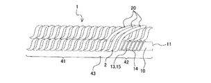
- FIG. 2 is an enlarged view of a main part showing the vicinity of the heat insulating material attachment range in the twisted tube of the twisted tube heat exchanger according to the embodiment of the present invention, and shows a state in which the heat insulating material is not attached.
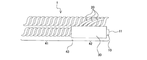
- FIG. 3 is a main part enlarged view showing the vicinity of the heat insulating material attachment range in the twisted tube of the twisted tube heat exchanger according to the embodiment of the present invention, and shows a state where the heat insulating material is attached.
- FIG. 4 is sectional drawing of the heat insulating material attachment range in the twisted tube of the twisted tube type heat exchanger which concerns on embodiment of this invention.
- FIG. 4 is a cross-sectional view perpendicular to the length direction of the first pipe 10. In other words, FIG. 4 is a cross-sectional view perpendicular to the tube axis direction of the first pipe 10.
- FIG. 4 is a cross-sectional view at a location where the first pipe 10 and the second pipe 20 are joined.
- the twisted pipe 1 has a first pipe 10 and a second pipe 20 provided in a spiral shape on the outer periphery of the first pipe 10.
- the 1st piping 10 and the 2nd piping 20 are formed with the material with favorable heat conductivity.
- the first pipe 10 and the second pipe 20 are made of, for example, copper or a copper alloy.
- the first pipe 10 is a pipe through which a first fluid such as water flows as described above.
- a spiral groove 13 around which the second pipe 20 is wound is formed on the outer periphery of the first pipe 10.
- spiral ridges 14 and spiral valleys 15 are alternately formed on the outer periphery of the first pipe 10.
- the trough part 15 is used as the groove part 13.
- a plurality of grooves 13 are formed. More specifically, in the present embodiment, three groove portions 13 are formed.
- the cross-sectional shape of the 1st piping 10 in the groove part 13 is a triangle. This is because three sides are formed because the first pipe 10 is formed by twisting the circular pipe into three strips. Therefore, when the four groove portions 13 are formed in the first pipe 10, the cross-sectional shape of the first pipe 10 in the groove portion 13 is a quadrangle.
- the refrigerant that heats the first fluid flows through the second pipe 20.
- the second pipe 20 is wound around the groove 13 of the first pipe 10.
- a plurality of (more specifically, three) grooves 13 are formed. For this reason, the same number of second pipes 20 are wound around the outer periphery of the first pipe 10.
- both ends of the second pipe 20 are wound around the outer periphery of the first pipe 10 in order to connect to a pipe that supplies the refrigerant to the second pipe 20 and a pipe that causes the refrigerant to flow out of the second pipe 20. It is not in a state. For this reason, the middle part, that is, a part of the second pipe 20 is wound around the outer peripheral part (that is, the groove part 13) of the middle part of the first pipe 10. And the 2nd piping 20 part wound around the groove part 13 of the 1st piping 10 and the 1st piping 10 are joined by solder etc., for example.
- a range where the first pipe 10 and the second pipe 20 are joined is defined as a first range 41. Further, a range that is present on the inlet side end 11 side of the first pipe 10 with respect to the first range 41 and is not joined to the first pipe 10 and the second pipe 20 is defined as a second range 42. Further, a boundary portion between the first range 41 and the second range 42 is defined as a boundary portion 43. That is, the boundary part 43 is the endmost part in the range where the first pipe 10 and the second pipe 20 are joined.
- the twisted tube 1 is provided with the above-described heat insulating material 30 in a partial range including the boundary portion 43.
- the heat insulating material 30 is wound so as to cover the outer peripheral portions of the first pipe 10 and the second pipe 20 in the boundary portion 43 and the outer peripheral portion of the first pipe 10 in the second range 42.
- the length of the heat insulating material 30 (specifically, the length of the twisted tube 1 in the tube axis direction) is not particularly limited. However, the workability of winding, the cost of the heat insulating material 30, and the condensation on the twisted tube 1 are assumed. In consideration of the length of the range, etc., about 20 cm in the direction from the boundary 43 to the second range 42 is appropriate.
- the heat insulating material 30 is formed of a material that does not easily dissolve components that cause corrosion in the first pipe 10 and the second pipe 20, and is preferably formed of, for example, a polyethylene foam resin.
- the heat insulating material 30 is fixed by, for example, applying an adhesive to the entire area of one surface and attaching the heat insulating material 30 to the twisted tube 1 with the adhesive.
- an adhesive that causes corrosion in the first pipe 10 and the second pipe 20 hydroochloric acid, sulfuric acid, acetic acid, etc.
- an acrylic adhesive is desirable.
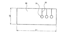
- FIG. 5 is a diagram showing an example of a heat insulating material wound around the twisted tube of the twisted tube heat exchanger according to the embodiment of the present invention.
- FIG. 6 is a figure which shows another example of the heat insulating material wound around the twisted tube of the twisted tube type heat exchanger which concerns on embodiment of this invention.
- the heat insulating material 30 before being wound around the twisted tube 1 has a rectangular shape, for example, and has the same number of holes 31 as the second pipe 20.
- the hole 31 is a hole into which the second pipe 20 is inserted.
- the diameter of the hole 31 is substantially the same as the outer diameter of the second pipe 20, for example.
- the position of the hole 31 is not particularly specified, but the hole 31 is formed at a substantially central position in the short side direction, for example.
- the length L2 of the short side of the heat insulating material 30 is a dimension which can cover the substantially perimeter of the outer peripheral part of the 1st piping 10 and the 2nd piping 20 in the boundary part 43 (refer FIG. 4). .
- the edge part of the longitudinal direction of the heat insulating material 30 is arrange
- the length L1 of the long side of the heat insulating material 30 is also about 20 cm.
- the 1st range 41 side rather than the boundary part 43 is also covered with the heat insulating material 30, it is good to lengthen the length L1 of the long side of the heat insulating material 30 only by the length which covers the 1st range 41.
- the heat insulating material 30 is formed with a cut from the hole 31 to the end of the heat insulating material 30.
- the insertion of the 2nd piping 20 to the hole 31 becomes easy by inserting the 2nd piping 20 in the hole 31 through the notch 32 from the edge part of the heat insulating material 30.
- the formation direction of the notch 32 is not specifically limited. The cut 32 may be formed toward the long side as shown in FIG. 5, or the cut 32 may be formed toward the short side as shown in FIG.
- the first fluid flows into the inside of the first pipe 10 from the inlet side end portion 11 of the first pipe 10 constituting the twisted pipe 1.
- the first fluid flows from the second range 42 toward the first range 41 in the first pipe 10.
- the first fluid is heated by the refrigerant flowing in the second pipe 20 while flowing in the first range 41.
- the heated first fluid flows out from the outlet side end portion 12 of the first pipe 10 to the outside of the twisted tube heat exchanger 100.
- the 1st fluid which flows through the 1st piping 10 part which exists in the 2nd range 42 is not yet heated by the refrigerant, it becomes the lowest temperature in the 1st fluid which exists in the 1st piping 10 here. Yes.
- the 1st piping part which exists in a 2nd range becomes low temperature rather than ambient temperature, and becomes an environment which is easy to dew condensation.
- the heat insulating material 30 is not provided in the twisted tube heat exchanger 100, dew condensation occurs in the first piping portion existing in the second range.
- the second range 42 is a range in which the first pipe 10 and the second pipe 20 are not joined, and a gap 2 is formed between the first pipe 10 and the second pipe 20 (see FIG. 2). .
- the dew condensation water is held in a bridge form in the second range 42 in the vicinity of the boundary portion 43 where the gap 2 is reduced.
- a refrigerant having a temperature higher than that of the first fluid flows through the second pipe 20 in order to heat the first fluid in the first pipe 10. That is, the second pipe 20 has a higher temperature than the first pipe 10.
- the portion acts as a temperature difference battery, and the second pipe 20 on the high temperature side is corroded. Resulting in.
- the heat insulating material 30 is wound around a part of the range including the boundary portion 43. That is, in the twisted tube heat exchanger 100, the condensed water bridged between the first pipe 10 and the second pipe 20 acts as a temperature difference battery, and heat insulation is provided at a location where corrosion occurs in the second pipe 20. The material 30 is wound.
- the twisted tube heat exchanger 100 according to the present embodiment indicates that the ambient air is cooled by a part of the range including the boundary part 43, that is, condensation is generated in a part of the range including the boundary part 43. Can be prevented from occurring. Therefore, the twisted tube heat exchanger 100 according to the present embodiment can suppress the corrosion of the second pipe 20.
- the twisted tube heat exchanger 100 has a shape in which the twisted tube 1 is wound in a plurality of stages (coil shape). For this reason, when the heat insulating material 30 is not provided, dew condensation water can bridge between the 1st piping 10 part which exists in the 2nd range 42, and the torsion pipe
- the range in which the heat insulating material 30 is wound and the twisted tube disposed above the range It will be in the state by which the heat insulating material 30 is arrange
- the spiral groove 13 is formed in the outer peripheral portion, and the first pipe 10 through which the first fluid flows and the groove 13 of the first pipe 10 are provided.
- a torsion pipe 1 having a part wound around and a second pipe 20 through which a refrigerant for heating the first fluid flows is provided.
- the twisted tube heat exchanger 100 according to the present embodiment includes the first pipe 10 and the first pipe 10 in the boundary portion 43 in a partial range including the boundary portion 43 between the first range 41 and the second range 42.
- the heat insulating material 30 wound so that the outer peripheral part of the 2 piping 20 and the outer peripheral part of the 1st piping 10 in the 2nd range 42 may be covered is provided.
- the condensed water bridged between the first pipe 10 and the second pipe 20 acts as a temperature difference battery, and corrosion occurs in the second pipe 20.
- a heat insulating material 30 is wound around the surface.
- the heat insulating material attaching method of winding the heat insulating material 30 is a method in which the heat insulating material 30 can be easily attached even in the twisted tube heat exchanger 100 having a complicated shape. For this reason, the twisted tube heat exchanger 100 according to the present embodiment can suppress the dew condensation water from bridging between the first piping 10 and the second piping 20, and the location acts as a temperature difference battery.
- the torsion tube type heat exchanger 100 according to the present embodiment is provided with the heat insulating material 30 only in a part, it is possible to suppress an increase in the material cost of the torsion tube type heat exchanger 100.
- the heat insulating material 30 is made of, for example, polyethylene foam resin. This is because the polyethylene foam resin is a material in which components that cause corrosion in the first pipe 10 and the second pipe 20 are difficult to elute.
- the heat insulating material 30 is formed with, for example, a hole 31 into which the second pipe 20 is inserted, and a cut 32 extending from the hole 31 to the end of the heat insulating material 30.
- the insertion of the 2nd piping 20 to the hole 31 becomes easy by inserting the 2nd piping 20 in the hole 31 through the notch 32 from the edge part of the heat insulating material 30. FIG. That is, it becomes easier to attach the heat insulating material 30.
- the twisted tube 1 when the twisted tube 1 is wound in a plurality of stages, the twisted tube disposed above the partial range (the range in which the heat insulating material 30 is wound) and the partial range.
- the heat insulating material 30 is arrange
Landscapes
- Engineering & Computer Science (AREA)
- Physics & Mathematics (AREA)
- Thermal Sciences (AREA)
- Mechanical Engineering (AREA)
- General Engineering & Computer Science (AREA)
- Heat-Exchange Devices With Radiators And Conduit Assemblies (AREA)
Abstract
捻り管式熱交換器は、外周部に螺旋状の溝部が形成され、内部に第1流体が流れる第1配管と、前記第1配管の前記溝部に一部が巻き付けられており、内部に前記第1流体を加熱する冷媒が流れる第2配管と、を有する捻り管を備え、前記第1配管と前記第2配管とが接合されている範囲を第1範囲と定義し、該第1範囲よりも前記第1配管の端部側に存在し、前記第1配管と前記第2配管とが接合されていない範囲を第2範囲と定義した場合、前記第1範囲と前記第2範囲との境界部を含む一部の範囲に、該境界部における前記第1配管及び前記第2配管の外周部と、前記第2範囲における前記第1配管の外周部とを覆うように巻き付けられている断熱材を備えた熱交換器である。
Description
本発明は、第1配管と、該第1配管の外周部に螺旋状に設けられた第2配管とを備えた捻り管式熱交換器に関するものである。
従来、第1配管と該第1配管の外周部に設けられた第2配管とを備え、第1配管内を流れる水等の第1流体を、第2配管内を流れる冷媒で加熱する熱交換器が知られている(例えば、特許文献1参照)。特許文献1に記載の熱交換器は、第1配管の長さ方向に沿って第2配管を配置している。換言すると、特許文献1に記載の熱交換器は、第1配管と第2配管とが平行に配置されている。そして、特許文献1に記載の熱交換器は、第1配管及び第2配管の外周部を樹脂層で覆い、第1配管に第2配管を密着させている。第1配管及び第2配管の外周部を覆うこの樹脂層は、断熱材としても機能する。また、この樹脂層は、押出法により、第1配管及び第2配管の外周部に設けられる。
また、従来、第1配管内を流れる水等の第1流体を、第2配管内を流れる冷媒で加熱する熱交換器として、捻り管式熱交換器というものも提案されている。この捻り管式熱交換器は、外周部に螺旋状の溝部が形成された第1配管と、該第1配管の溝部に巻き付けられた第2配管とを備えている。すなわち、第2配管は、第1配管の外周部に螺旋状に設けられている。
特許文献1に記載の熱交換器は、断熱材として機能する樹脂層を押出法により形成している。つまり、特許文献1に記載の熱交換器は、熱交換器全体に断熱材を設ける構成となっている。このため、特許文献1のように断熱材を設ける構成は、熱交換器の材料費が増加してしまうという課題があった。
また、捻り管式熱交換器は、第1配管の外周部に第2配管が螺旋状に設けられており、複雑な形状となっている。このため、捻り管式熱交換器の外周部に、押出法によって樹脂層を形成することは、現実的に不可能である。このため、従来の捻り管式熱交換器は、外周部に断熱層を備えられず、第2配管が腐食してしまうという課題があった。
詳しくは、第2配管の両端部は、該第2配管に冷媒を供給する配管及び該第2配管から冷媒を流出させる配管と接続するため、第1配管の外周部に巻かれていない状態となっている。このため、第2配管の途中部が、第1配管の途中部の外周部に巻き付けられている。そして、第1配管の外周部に巻き付けられている第2配管部分と、第1配管とが、例えば半田等により接合されている。以下では、第1配管と第2配管とが接合されている範囲を第1範囲と称し、第1範囲よりも第1配管の端部側に存在し、第1配管と第2配管とが接合されていない範囲を第2範囲と称することとする。
捻り管式熱交換器は上述のように構成されているので、第1配管に流入した第1流体は、まず第2範囲を流れる。その後、第1配管内の第1流体は、第1範囲に流入し、第2配管内を流れる冷媒によって加熱される。すなわち、第2範囲に存在する第1配管部分を流れる第1流体は、未だ冷媒によって加熱されていないため、低温となっている。このため、第2範囲に存在する第1配管部分は、周囲温度よりも低温となり、結露しやすい。また、第2範囲は、第1配管と第2配管とが接合されていない範囲であり、第1配管と第2配管との間に隙間が形成されている。このため、結露が発生した場合、第1配管と第2配管との間の隙間が小さくなる第2範囲では、つまり、第1範囲との境界部近傍となる第2範囲では、結露水がブリッジする形で保持される。ここで、第2配管には、第1配管内の第1流体を加熱するため、第1流体よりも高温の冷媒が流れている。すなわち、第2配管は、第1配管よりも高温となっている。このため、第1配管と第2配管との間に結露水がブリッジする形で保持されると、当該部分が温度差電池として作用し、高温側となる第2配管に腐食が発生してしまう。
本発明は、上述のような課題を解決するためになされたものであり、第2配管の腐食を抑制でき、材料費の増加を抑制することも可能な捻り管式熱交換器を提供することを目的とする。
本発明に係る捻り管式熱交換器は、外周部に螺旋状の溝部が形成され、内部に第1流体が流れる第1配管と、前記第1配管の前記溝部に一部が巻き付けられており、内部に前記第1流体を加熱する冷媒が流れる第2配管と、を有する捻り管を備え、前記第1配管と前記第2配管とが接合されている範囲を第1範囲と定義し、該第1範囲よりも前記第1配管の端部側に存在し、前記第1配管と前記第2配管とが接合されていない範囲を第2範囲と定義した場合、前記第1範囲と前記第2範囲との境界部を含む一部の範囲に、該境界部における前記第1配管及び前記第2配管の外周部と、前記第2範囲における前記第1配管の外周部とを覆うように巻き付けられている断熱材を備えた熱交換器である。
本発明に係る捻り管式熱交換器は、第2範囲から第1範囲へ向かって第1流体が流れる構成として用いることができる。ここで、本発明に係る捻り管式熱交換器は、第1範囲と第2範囲との境界部における第1配管及び第2配管の外周部と、第2範囲における第1配管の外周部とを覆うように、断熱材が巻き付けられている。つまり、本発明に係る捻り管式熱交換器は、第1配管と第2配管との間にブリッジした結露水が温度差電池として作用し、第2配管に腐食が発生する箇所に断熱材を巻き付けている。断熱材を巻き付けるという断熱材の取り付け方法は、押出法を用いる断熱材の取り付け方法と異なり、形状が複雑な捻り管式熱交換器においても容易に断熱材を取り付けられる方法である。このため、本発明に係る捻り管式熱交換器は、第1配管と第2配管との間に結露水がブリッジすることを抑制でき、当該箇所が温度差電池として作用して第2配管に腐食が発生することを抑制できる。また、本発明に係る捻り管式熱交換器は、一部分のみに断熱材を設けているので、捻り管式熱交換器の材料費が増加することも抑制できる。
実施の形態.
図1は、本発明の実施の形態に係る捻り管式熱交換器を示す斜視図である。
捻り管式熱交換器100は、捻り管1を備えている。捻り管1の詳細は後述するが、該捻り管1は、後述のように、水等の第1流体が流れる第1配管10と、第1流体を加熱する冷媒が流れる第2配管20と、を備えている(後述の図2及び図3を参照)。また、本実施の形態に係る捻り管式熱交換器100は、捻り管1の一部に断熱材30が巻き付けられている。なお、本実施の形態に係る捻り管式熱交換器100は、長尺の(長さが長い)捻り管1を用いている。このため、本実施の形態に係る捻り管式熱交換器100は、捻り管1が複数段のとぐろ状(コイル状)に巻かれた形状となっている。とぐろ状部分の辺の長さ及び段数は、捻り管1の長さに応じて、適宜決定すればよい。
捻り管式熱交換器100は、例えば、ヒートポンプ式給湯機用の水冷媒熱交換器として用いられる。この場合、第1流体となる水が、捻り管式熱交換器100で加熱される。具体的には水は、捻り管1の入口側端部11から、該捻り管1の内部に流入する。より詳しくは、水は、捻り管1を構成する第1配管10の入口側端部11から、該第1配管10の内部に流入する。そして、第1配管10に流入したこの水は、出口側端部12から流出するまでの間に、第2配管20の内部を流れる冷媒によって加熱され、湯となる。
続いて、本実施の形態に係る捻り管1の詳細について説明する。
図2は、本発明の実施の形態に係る捻り管式熱交換器の捻り管における断熱材取り付け範囲近傍を示す要部拡大図であり、断熱材が取り付けられていない状態を示す図である。図3は、本発明の実施の形態に係る捻り管式熱交換器の捻り管における断熱材取り付け範囲近傍を示す要部拡大図であり、断熱材が取り付けられている状態を示す図である。また、図4は、本発明の実施の形態に係る捻り管式熱交換器の捻り管における断熱材取り付け範囲の断面図である。なお、図4は、第1配管10の長さ方向と垂直な断面図となっている。換言すると、図4は、第1配管10の管軸方向と垂直な断面図となっている。また、図4は、第1配管10と第2配管20とが接合されている箇所での断面図となっている。
捻り管1は、第1配管10と、該第1配管10の外周部に螺旋状に設けられた第2配管20と、を有している。第1配管10及び第2配管20は、熱伝導性が良好な材質で形成されている。本実施の形態では、第1配管10及び第2配管20は、例えば、銅又は銅合金によって形成されている。
第1配管10は、上述のように、内部に水等の第1流体が流れるものである。第1配管10の外周部には、第2配管20が巻き付けられる螺旋状の溝部13が形成されている。詳しくは、本実施の形態では、第1配管10の外周部に、螺旋状の山部14及び螺旋状の谷部15を交互に形成している。そして、谷部15を溝部13としている。なお、本実施の形態では、複数条の溝部13を形成している。より詳しくは、本実施の形態では、3条の溝部13を形成している。このため、図4に示すように、溝部13での第1配管10の断面形状は、三角形となっている。これは、円管を3条に捻って第1配管10を形成しているため、3つの辺が形成されるからである。したがって、第1配管10に4条の溝部13を形成した場合、溝部13での第1配管10の断面形状は四角形となる。
第2配管20は、上述のように、内部に第1流体を加熱する冷媒が流れるものである。第2配管20は、第1配管10の溝部13に巻き付けられている。なお、本実施の形態では、上述のように、複数条(より詳しくは3条)の溝部13が形成されている。このため、第1配管10の外周部には、条数と同数の第2配管20が巻き付けられている。
ここで、第2配管20の両端部は、該第2配管20に冷媒を供給する配管及び該第2配管20から冷媒を流出させる配管と接続するため、第1配管10の外周部に巻かれていない状態となっている。このため、第2配管20の途中部つまり一部が、第1配管10の途中部の外周部(つまり溝部13)に巻き付けられている。そして、第1配管10の溝部13に巻き付けられている第2配管20部分と、第1配管10とが、例えば半田等により接合されている。
なお、本実施の形態では、第1配管10と第2配管20とが接合されている範囲を第1範囲41と定義する。また、第1範囲41よりも第1配管10の入口側端部11側に存在し、第1配管10と第2配管20とが接合されていない範囲を第2範囲42と定義する。また、第1範囲41と第2範囲42との境界部を、境界部43と定義する。つまり、境界部43は、第1配管10と第2配管20とが接合されている範囲の、最も端の箇所である。
図3に示すように、本実施の形態に係る捻り管1は、境界部43を含む一部の範囲に、上述の断熱材30を設けている。詳しくは、断熱材30は、境界部43における第1配管10及び第2配管20の外周部と、第2範囲42における第1配管10の外周部とを覆うように巻き付けられている。なお、断熱材30の長さ(詳しくは捻り管1の管軸方向の長さ)については、特に制限はないが、巻き付ける作業性、断熱材30のコスト、及び捻り管1における結露が想定される範囲の長さ等を考慮すると、境界部43から第2範囲42方向に約20cmが適当である。また、断熱材30は、第1配管10及び第2配管20に腐食を発生させる成分が溶出し難い材質で形成されることが好ましく、例えばポリエチレン発泡樹脂で形成されるのが好ましい。
断熱材30は、例えば片面全域に接着剤が塗布され、該接着剤によって捻り管1に貼り付けられることにより、固定されている。このように断熱材30を固定する場合、使用する接着剤としては、第1配管10及び第2配管20に腐食を発生させる成分(塩酸、硫酸、酢酸等)が溶出するようなものは避けた方が良く、例えばアクリル系の接着剤が望ましい。
図5は、本発明の実施の形態に係る捻り管式熱交換器の捻り管に巻き付けられる断熱材の一例を示す図である。また、図6は、本発明の実施の形態に係る捻り管式熱交換器の捻り管に巻き付けられる断熱材の別の一例を示す図である。
捻り管1に巻き付けられる前の断熱材30は、例えば長方形状をしており、第2配管20と同数の穴31が形成されている。穴31は、第2配管20が挿入される穴である。穴31の直径は、例えば、第2配管20の外径と略同寸法となっている。なお、穴31の位置については特に規定はないが、例えば短辺方向の略中心位置に穴31が形成される。また、断熱材30の短辺の長さL2は、境界部43において第1配管10及び第2配管20の外周部のほぼ全周を覆うことができる寸法であることが好ましい(図4参照)。また、本実施の形態では、図3に示すように、断熱材30の長手方向の端部が、境界部43近傍に配置されている。このため、境界部43から第2範囲42方向に約20cmの範囲を断熱材30で覆う場合、断熱材30の長辺の長さL1も約20cmとすることが好ましい。なお、境界部43よりも第1範囲41側も断熱材30で覆う場合、第1範囲41を覆う分の長さだけ、断熱材30の長辺の長さL1を長くするとよい。
また、断熱材30には、穴31から当該断熱材30の端部に至る切り込みが形成されている。穴31に第2配管20を挿入する際、断熱材30の端部から切り込み32を通して穴31に第2配管20を挿入することにより、穴31への第2配管20の挿入が容易となる。なお、切り込み32の形成方向は、特に限定されない。図5に示すように長辺に向かって切り込み32を形成してもよいし、図6に示すように短辺に向かって切り込み32を形成してもよい。
続いて、本実施の形態に係る捻り管式熱交換器100における第1流体の加熱動作について説明する。
第1流体は、捻り管1を構成する第1配管10の入口側端部11から、該第1配管10の内部に流入する。この第1流体は、第1配管10の内部を、第2範囲42から第1範囲41に向かって流れる。そして、第1流体は、第1範囲41を流れている間に、第2配管20の内部を流れる冷媒によって加熱される。この加熱された第1流体は、第1配管10の出口側端部12から、捻り管式熱交換器100の外部に流出する。
第1流体は、捻り管1を構成する第1配管10の入口側端部11から、該第1配管10の内部に流入する。この第1流体は、第1配管10の内部を、第2範囲42から第1範囲41に向かって流れる。そして、第1流体は、第1範囲41を流れている間に、第2配管20の内部を流れる冷媒によって加熱される。この加熱された第1流体は、第1配管10の出口側端部12から、捻り管式熱交換器100の外部に流出する。
ここで、第2範囲42に存在する第1配管10部分を流れる第1流体は、未だ冷媒によって加熱されていないため、第1配管10内に存在する第1流体の中で最も低温となっている。このため、第2範囲に存在する第1配管部分は、周囲温度よりも低温となり、結露しやすい環境となる。このため、捻り管式熱交換器100に断熱材30が設けられていない場合、第2範囲に存在する第1配管部分に結露が発生する。
第2範囲42は、第1配管10と第2配管20とが接合されていない範囲であり、第1配管10と第2配管20との間に隙間2が形成されている(図2参照)。このため、第2範囲に存在する第1配管部分に結露が発生した場合、隙間2が小さくなる境界部43近傍の第2範囲42では、結露水がブリッジする形で保持される。ここで、第2配管20には、第1配管10内の第1流体を加熱するため、第1流体よりも高温の冷媒が流れている。すなわち、第2配管20は、第1配管10よりも高温となっている。このため、第1配管10と第2配管20との間に結露水がブリッジする形で保持されると、当該部分が温度差電池として作用し、高温側となる第2配管20に腐食が発生してしまう。
しかしながら、本実施の形態に係る捻り管式熱交換器100においては、境界部43を含む一部の範囲に断熱材30が巻き付けられている。すなわち、捻り管式熱交換器100においては、第1配管10と第2配管20との間にブリッジした結露水が温度差電池として作用し、第2配管20に腐食が発生する箇所に、断熱材30が巻き付けられている。このため、本実施の形態に係る捻り管式熱交換器100は、境界部43を含む一部の範囲によって周辺空気が冷却されることを、つまり、境界部43を含む一部の範囲に結露が発生することを抑制できる。したがって、本実施の形態に係る捻り管式熱交換器100は、第2配管20の腐食を抑制することができる。
なお、上述のように、本実施の形態に係る捻り管式熱交換器100は、捻り管1が複数段のとぐろ状(コイル状)に巻かれた形状となっている。このため、断熱材30が設けられていない場合、第2範囲42に存在する第1配管10部分と当該部分の上方に配置されている捻り管1部分との間でも、結露水がブリッジする可能性がある。このように結露水がブリッジした場合、当該箇所が温度差電池として作用し、高温側となる第2配管20に腐食が発生してしまう。しかしながら、図1及び図3に示すように、本実施の形態に係る捻り管式熱交換器100においては、断熱材30が巻かれている範囲と、該範囲の上方に配置されている捻り管1部分との間に、断熱材30が配置された状態となる。このため、本実施の形態に係る捻り管式熱交換器100においては、第1範囲41の第2配管20の腐食を抑制することもできる。
以上、本実施の形態に係る捻り管式熱交換器100は、外周部に螺旋状の溝部13が形成され、内部に第1流体が流れる第1配管10と、第1配管10の溝部13に一部が巻き付けられており、内部に第1流体を加熱する冷媒が流れる第2配管20と、を有する捻り管1を備えている。そして、本実施の形態に係る捻り管式熱交換器100は、第1範囲41と第2範囲42との境界部43を含む一部の範囲に、該境界部43における第1配管10及び第2配管20の外周部と、第2範囲42における第1配管10の外周部とを覆うように巻き付けられている断熱材30を備えている。
本実施の形態に係る捻り管式熱交換器100は、第1配管10と第2配管20との間にブリッジした結露水が温度差電池として作用し、第2配管20に腐食が発生する箇所に断熱材30を巻き付けている。断熱材30を巻き付けるという断熱材の取り付け方法は、押出法を用いる断熱材の取り付け方法と異なり、形状が複雑な捻り管式熱交換器100においても容易に断熱材30を取り付けられる方法である。このため、本実施の形態に係る捻り管式熱交換器100は、第1配管10と第2配管20との間に結露水がブリッジすることを抑制でき、当該箇所が温度差電池として作用して第2配管20に腐食が発生することを抑制できる。また、本実施の形態に係る捻り管式熱交換器100は、一部分のみに断熱材30を設けているので、捻り管式熱交換器100の材料費が増加することも抑制できる。
なお、断熱材30は、例えば、ポリエチレン発泡樹脂で形成されている。ポリエチレン発泡樹脂は、第1配管10及び第2配管20に腐食を発生させる成分が溶出し難い材質だからである。
また、断熱材30は、例えば、第2配管20が挿入される穴31と、該穴31から当該断熱材30の端部に至る切り込み32とが形成されている。穴31に第2配管20を挿入する際、断熱材30の端部から切り込み32を通して穴31に第2配管20を挿入することにより、穴31への第2配管20の挿入が容易となる。すなわち、断熱材30の取り付けが更に容易となる。
また、捻り管1が複数段のとぐろ状に巻かれている場合、前記一部の範囲(断熱材30が巻き付けられている範囲)と、該一部の範囲の上方に配置されている捻り管1部分との間に、断熱材30が配置されている。前記一部の範囲(断熱材30が巻き付けられている範囲)の上方に配置されている捻り管1部分の第2配管20の腐食も抑制することができる。
1 捻り管、2 隙間、10 第1配管、11 入口側端部、12 出口側端部、13 溝部、14 山部、15 谷部、20 第2配管、30 断熱材、31 穴、32 切り込み、41 第1範囲、42 第2範囲、43 境界部、100 捻り管式熱交換器。
Claims (5)
- 外周部に螺旋状の溝部が形成され、内部に第1流体が流れる第1配管と、
前記第1配管の前記溝部に一部が巻き付けられており、内部に前記第1流体を加熱する冷媒が流れる第2配管と、
を有する捻り管を備え、
前記第1配管と前記第2配管とが接合されている範囲を第1範囲と定義し、該第1範囲よりも前記第1配管の端部側に存在し、前記第1配管と前記第2配管とが接合されていない範囲を第2範囲と定義した場合、
前記第1範囲と前記第2範囲との境界部を含む一部の範囲に、該境界部における前記第1配管及び前記第2配管の外周部と、前記第2範囲における前記第1配管の外周部とを覆うように巻き付けられている断熱材を備えた捻り管式熱交換器。 - 前記断熱材は、ポリエチレン発泡樹脂で形成されている請求項1に記載の捻り管式熱交換器。
- 前記断熱材は、前記第2配管が挿入される穴と、該穴から当該断熱材の端部に至る切り込みとが形成されている請求項1又は請求項2に記載の捻り管式熱交換器。
- 前記捻り管は、複数段のとぐろ状に巻かれており、
前記一部の範囲と、該一部の範囲の上方に配置されている前記捻り管部分との間に、前記断熱材が配置されている請求項1~請求項3のいずれか一項に記載の捻り管式熱交換器。 - 前記第1流体が前記第2範囲から前記第1範囲へ向かって流れる構成である請求項1~請求項4に記載の捻り管式熱交換器。
Priority Applications (4)
| Application Number | Priority Date | Filing Date | Title |
|---|---|---|---|
| PCT/JP2017/001447 WO2018134899A1 (ja) | 2017-01-18 | 2017-01-18 | 捻り管式熱交換器 |
| JP2018562771A JP6682017B2 (ja) | 2017-01-18 | 2017-01-18 | 捻り管式熱交換器 |
| EP17797221.3A EP3370026B1 (en) | 2017-01-18 | 2017-01-18 | Twisted pipe heat exchanger |
| CN201790000282.2U CN208765538U (zh) | 2017-01-18 | 2017-01-18 | 螺旋管式热交换器 |
Applications Claiming Priority (1)
| Application Number | Priority Date | Filing Date | Title |
|---|---|---|---|
| PCT/JP2017/001447 WO2018134899A1 (ja) | 2017-01-18 | 2017-01-18 | 捻り管式熱交換器 |
Publications (1)
| Publication Number | Publication Date |
|---|---|
| WO2018134899A1 true WO2018134899A1 (ja) | 2018-07-26 |
Family
ID=62907939
Family Applications (1)
| Application Number | Title | Priority Date | Filing Date |
|---|---|---|---|
| PCT/JP2017/001447 WO2018134899A1 (ja) | 2017-01-18 | 2017-01-18 | 捻り管式熱交換器 |
Country Status (4)
| Country | Link |
|---|---|
| EP (1) | EP3370026B1 (ja) |
| JP (1) | JP6682017B2 (ja) |
| CN (1) | CN208765538U (ja) |
| WO (1) | WO2018134899A1 (ja) |
Citations (6)
| Publication number | Priority date | Publication date | Assignee | Title |
|---|---|---|---|---|
| JPS5580685U (ja) * | 1978-11-28 | 1980-06-03 | ||
| JPS5724870U (ja) * | 1980-07-18 | 1982-02-09 | ||
| JPS6234662U (ja) * | 1985-08-16 | 1987-02-28 | ||
| JP2004347178A (ja) | 2003-05-20 | 2004-12-09 | Furukawa Electric Co Ltd:The | 熱交換器 |
| JP2008096043A (ja) * | 2006-10-13 | 2008-04-24 | Mitsubishi Electric Corp | 捩り管形熱交換器 |
| JP2009002631A (ja) * | 2007-06-25 | 2009-01-08 | Furukawa Electric Co Ltd:The | 熱交換器、および熱交換システム |
Family Cites Families (2)
| Publication number | Priority date | Publication date | Assignee | Title |
|---|---|---|---|---|
| JP2005164166A (ja) * | 2003-12-04 | 2005-06-23 | Kobelco & Materials Copper Tube Inc | 熱交換器 |
| WO2014199479A1 (ja) * | 2013-06-13 | 2014-12-18 | 三菱電機株式会社 | ヒートポンプ装置 |
-
2017
- 2017-01-18 CN CN201790000282.2U patent/CN208765538U/zh not_active Expired - Fee Related
- 2017-01-18 WO PCT/JP2017/001447 patent/WO2018134899A1/ja unknown
- 2017-01-18 JP JP2018562771A patent/JP6682017B2/ja not_active Expired - Fee Related
- 2017-01-18 EP EP17797221.3A patent/EP3370026B1/en active Active
Patent Citations (6)
| Publication number | Priority date | Publication date | Assignee | Title |
|---|---|---|---|---|
| JPS5580685U (ja) * | 1978-11-28 | 1980-06-03 | ||
| JPS5724870U (ja) * | 1980-07-18 | 1982-02-09 | ||
| JPS6234662U (ja) * | 1985-08-16 | 1987-02-28 | ||
| JP2004347178A (ja) | 2003-05-20 | 2004-12-09 | Furukawa Electric Co Ltd:The | 熱交換器 |
| JP2008096043A (ja) * | 2006-10-13 | 2008-04-24 | Mitsubishi Electric Corp | 捩り管形熱交換器 |
| JP2009002631A (ja) * | 2007-06-25 | 2009-01-08 | Furukawa Electric Co Ltd:The | 熱交換器、および熱交換システム |
Also Published As
| Publication number | Publication date |
|---|---|
| JPWO2018134899A1 (ja) | 2019-04-04 |
| EP3370026A4 (en) | 2018-09-05 |
| JP6682017B2 (ja) | 2020-04-15 |
| EP3370026B1 (en) | 2019-06-05 |
| CN208765538U (zh) | 2019-04-19 |
| EP3370026A1 (en) | 2018-09-05 |
Similar Documents
| Publication | Publication Date | Title |
|---|---|---|
| JP4211041B2 (ja) | ヒートポンプ給湯機 | |
| JP6687022B2 (ja) | 冷凍サイクル装置 | |
| JP2007218486A (ja) | 熱交換器用伝熱管及びこれを用いた熱交換器 | |
| JP2005164166A (ja) | 熱交換器 | |
| JP2005133999A (ja) | ヒートポンプ式給湯機 | |
| JP2009047394A (ja) | 捩り管形熱交換器の製造方法 | |
| WO2018134899A1 (ja) | 捻り管式熱交換器 | |
| JP4224793B2 (ja) | 熱交換器及びその製造方法 | |
| JP2005221172A (ja) | 給湯用熱交換器 | |
| JP2005083667A (ja) | 熱交換器 | |
| JP2008116112A (ja) | 熱交換器 | |
| JP4075732B2 (ja) | ヒートポンプ式給湯機用の熱交換器 | |
| JP6861848B2 (ja) | 熱交換器の製造方法及び熱交換器 | |
| JP2008249163A (ja) | 給湯用熱交換器 | |
| JP5404589B2 (ja) | 捩り管形熱交換器 | |
| RU2502931C2 (ru) | Теплообменник труба в трубе | |
| JP5656786B2 (ja) | 異径捩り管形熱交換器の製造方法 | |
| JP5289088B2 (ja) | 熱交換器及び伝熱管 | |
| RU62694U1 (ru) | Теплообменный элемент | |
| KR101016696B1 (ko) | 턴핀형 열교환기 및 그의 제조방법 | |
| JP5794952B2 (ja) | 捩り管形熱交換器 | |
| KR101725852B1 (ko) | 핀튜브 조립체 제조방법 및 이에 의해 제작된 핀튜브 조립체 | |
| JP2005098612A (ja) | 熱交換器及びその製造方法 | |
| EP2735836B1 (en) | Heat exchanger | |
| RU2785883C2 (ru) | Крепление труб в змеевиковых теплообменниках |
Legal Events
| Date | Code | Title | Description |
|---|---|---|---|
| ENP | Entry into the national phase |
Ref document number: 2018562771 Country of ref document: JP Kind code of ref document: A |
|
| NENP | Non-entry into the national phase |
Ref country code: DE |