JP4269318B2 - Vibration agitator, treatment apparatus and treatment method using the same - Google Patents
Vibration agitator, treatment apparatus and treatment method using the same Download PDFInfo
- Publication number
- JP4269318B2 JP4269318B2 JP2003507032A JP2003507032A JP4269318B2 JP 4269318 B2 JP4269318 B2 JP 4269318B2 JP 2003507032 A JP2003507032 A JP 2003507032A JP 2003507032 A JP2003507032 A JP 2003507032A JP 4269318 B2 JP4269318 B2 JP 4269318B2
- Authority
- JP
- Japan
- Prior art keywords
- vibrating
- vibration
- electrode member
- blade
- electrode
- Prior art date
- Legal status (The legal status is an assumption and is not a legal conclusion. Google has not performed a legal analysis and makes no representation as to the accuracy of the status listed.)
- Expired - Fee Related
Links
- 238000011282 treatment Methods 0.000 title claims description 97
- 238000000034 method Methods 0.000 title claims description 43
- 239000007788 liquid Substances 0.000 claims abstract description 138
- 238000012545 processing Methods 0.000 claims abstract description 95
- 238000003756 stirring Methods 0.000 claims abstract description 79
- 238000007747 plating Methods 0.000 claims description 84
- 238000004070 electrodeposition Methods 0.000 claims description 72
- 238000004381 surface treatment Methods 0.000 claims description 64
- 238000000576 coating method Methods 0.000 claims description 57
- 239000011248 coating agent Substances 0.000 claims description 51
- 238000009413 insulation Methods 0.000 claims description 22
- 238000005323 electroforming Methods 0.000 claims description 21
- 238000007743 anodising Methods 0.000 claims description 20
- 238000013019 agitation Methods 0.000 claims description 19
- 229920003002 synthetic resin Polymers 0.000 claims description 13
- 239000000057 synthetic resin Substances 0.000 claims description 13
- 238000005238 degreasing Methods 0.000 claims description 12
- 239000000463 material Substances 0.000 claims description 12
- 229920003051 synthetic elastomer Polymers 0.000 claims description 6
- 239000005061 synthetic rubber Substances 0.000 claims description 6
- 238000005498 polishing Methods 0.000 claims description 4
- 238000002048 anodisation reaction Methods 0.000 claims description 3
- 238000002203 pretreatment Methods 0.000 claims description 2
- 238000003672 processing method Methods 0.000 claims 7
- 238000010292 electrical insulation Methods 0.000 abstract description 4
- 229920001875 Ebonite Polymers 0.000 abstract description 3
- RTAQQCXQSZGOHL-UHFFFAOYSA-N Titanium Chemical compound [Ti] RTAQQCXQSZGOHL-UHFFFAOYSA-N 0.000 description 35
- 239000010936 titanium Substances 0.000 description 29
- 229910052719 titanium Inorganic materials 0.000 description 28
- XLYOFNOQVPJJNP-UHFFFAOYSA-N water Substances O XLYOFNOQVPJJNP-UHFFFAOYSA-N 0.000 description 20
- 229910052751 metal Inorganic materials 0.000 description 19
- 239000002184 metal Substances 0.000 description 19
- 230000008569 process Effects 0.000 description 13
- 230000003647 oxidation Effects 0.000 description 12
- 238000007254 oxidation reaction Methods 0.000 description 12
- BASFCYQUMIYNBI-UHFFFAOYSA-N platinum Substances [Pt] BASFCYQUMIYNBI-UHFFFAOYSA-N 0.000 description 12
- 230000001954 sterilising effect Effects 0.000 description 12
- 238000005868 electrolysis reaction Methods 0.000 description 10
- 238000005406 washing Methods 0.000 description 10
- 239000000243 solution Substances 0.000 description 9
- 239000010935 stainless steel Substances 0.000 description 9
- 229910001220 stainless steel Inorganic materials 0.000 description 9
- PXHVJJICTQNCMI-UHFFFAOYSA-N Nickel Chemical compound [Ni] PXHVJJICTQNCMI-UHFFFAOYSA-N 0.000 description 8
- QAOWNCQODCNURD-UHFFFAOYSA-N Sulfuric acid Chemical compound OS(O)(=O)=O QAOWNCQODCNURD-UHFFFAOYSA-N 0.000 description 8
- 230000000694 effects Effects 0.000 description 8
- XEEYBQQBJWHFJM-UHFFFAOYSA-N iron Substances [Fe] XEEYBQQBJWHFJM-UHFFFAOYSA-N 0.000 description 8
- 229910000831 Steel Inorganic materials 0.000 description 7
- 229910052802 copper Inorganic materials 0.000 description 7
- 239000010949 copper Substances 0.000 description 7
- 229920001971 elastomer Polymers 0.000 description 7
- 239000012530 fluid Substances 0.000 description 7
- 239000008267 milk Substances 0.000 description 7
- 235000013336 milk Nutrition 0.000 description 7
- 210000004080 milk Anatomy 0.000 description 7
- 239000005060 rubber Substances 0.000 description 7
- 239000010959 steel Substances 0.000 description 7
- 238000004659 sterilization and disinfection Methods 0.000 description 7
- RYGMFSIKBFXOCR-UHFFFAOYSA-N Copper Chemical compound [Cu] RYGMFSIKBFXOCR-UHFFFAOYSA-N 0.000 description 6
- KWYUFKZDYYNOTN-UHFFFAOYSA-M Potassium hydroxide Chemical group [OH-].[K+] KWYUFKZDYYNOTN-UHFFFAOYSA-M 0.000 description 6
- 229910045601 alloy Inorganic materials 0.000 description 6
- 239000000956 alloy Substances 0.000 description 6
- 239000000203 mixture Substances 0.000 description 6
- 230000004048 modification Effects 0.000 description 6
- 238000012986 modification Methods 0.000 description 6
- 239000003973 paint Substances 0.000 description 6
- 229910052697 platinum Inorganic materials 0.000 description 6
- UFHFLCQGNIYNRP-UHFFFAOYSA-N Hydrogen Chemical compound [H][H] UFHFLCQGNIYNRP-UHFFFAOYSA-N 0.000 description 5
- 229910052782 aluminium Inorganic materials 0.000 description 5
- XAGFODPZIPBFFR-UHFFFAOYSA-N aluminium Chemical compound [Al] XAGFODPZIPBFFR-UHFFFAOYSA-N 0.000 description 5
- 239000002585 base Substances 0.000 description 5
- 239000006185 dispersion Substances 0.000 description 5
- 238000009713 electroplating Methods 0.000 description 5
- 229910052742 iron Inorganic materials 0.000 description 5
- 229910052759 nickel Inorganic materials 0.000 description 5
- 230000001699 photocatalysis Effects 0.000 description 5
- 241000894006 Bacteria Species 0.000 description 4
- GWEVSGVZZGPLCZ-UHFFFAOYSA-N Titan oxide Chemical compound O=[Ti]=O GWEVSGVZZGPLCZ-UHFFFAOYSA-N 0.000 description 4
- 125000002091 cationic group Chemical group 0.000 description 4
- 239000011777 magnesium Substances 0.000 description 4
- 239000013307 optical fiber Substances 0.000 description 4
- 125000006850 spacer group Chemical group 0.000 description 4
- FYYHWMGAXLPEAU-UHFFFAOYSA-N Magnesium Chemical compound [Mg] FYYHWMGAXLPEAU-UHFFFAOYSA-N 0.000 description 3
- 239000003513 alkali Substances 0.000 description 3
- 150000001450 anions Chemical class 0.000 description 3
- 230000008901 benefit Effects 0.000 description 3
- 230000000052 comparative effect Effects 0.000 description 3
- 239000002131 composite material Substances 0.000 description 3
- 230000007423 decrease Effects 0.000 description 3
- 239000000839 emulsion Substances 0.000 description 3
- 238000000605 extraction Methods 0.000 description 3
- 230000005294 ferromagnetic effect Effects 0.000 description 3
- 238000002347 injection Methods 0.000 description 3
- 239000007924 injection Substances 0.000 description 3
- 229910052749 magnesium Inorganic materials 0.000 description 3
- 230000005291 magnetic effect Effects 0.000 description 3
- 238000004519 manufacturing process Methods 0.000 description 3
- KERTUBUCQCSNJU-UHFFFAOYSA-L nickel(2+);disulfamate Chemical compound [Ni+2].NS([O-])(=O)=O.NS([O-])(=O)=O KERTUBUCQCSNJU-UHFFFAOYSA-L 0.000 description 3
- 230000000149 penetrating effect Effects 0.000 description 3
- 238000003825 pressing Methods 0.000 description 3
- 229920005989 resin Polymers 0.000 description 3
- 239000011347 resin Substances 0.000 description 3
- 239000000725 suspension Substances 0.000 description 3
- OGIDPMRJRNCKJF-UHFFFAOYSA-N titanium oxide Inorganic materials [Ti]=O OGIDPMRJRNCKJF-UHFFFAOYSA-N 0.000 description 3
- HZAXFHJVJLSVMW-UHFFFAOYSA-N 2-Aminoethan-1-ol Chemical compound NCCO HZAXFHJVJLSVMW-UHFFFAOYSA-N 0.000 description 2
- VEXZGXHMUGYJMC-UHFFFAOYSA-M Chloride anion Chemical compound [Cl-] VEXZGXHMUGYJMC-UHFFFAOYSA-M 0.000 description 2
- 241000588724 Escherichia coli Species 0.000 description 2
- YCKRFDGAMUMZLT-UHFFFAOYSA-N Fluorine atom Chemical compound [F] YCKRFDGAMUMZLT-UHFFFAOYSA-N 0.000 description 2
- NBIIXXVUZAFLBC-UHFFFAOYSA-N Phosphoric acid Chemical compound OP(O)(O)=O NBIIXXVUZAFLBC-UHFFFAOYSA-N 0.000 description 2
- QAOWNCQODCNURD-UHFFFAOYSA-L Sulfate Chemical compound [O-]S([O-])(=O)=O QAOWNCQODCNURD-UHFFFAOYSA-L 0.000 description 2
- 229910001069 Ti alloy Inorganic materials 0.000 description 2
- 239000000853 adhesive Substances 0.000 description 2
- 230000001070 adhesive effect Effects 0.000 description 2
- WNROFYMDJYEPJX-UHFFFAOYSA-K aluminium hydroxide Chemical compound [OH-].[OH-].[OH-].[Al+3] WNROFYMDJYEPJX-UHFFFAOYSA-K 0.000 description 2
- BFNBIHQBYMNNAN-UHFFFAOYSA-N ammonium sulfate Chemical compound N.N.OS(O)(=O)=O BFNBIHQBYMNNAN-UHFFFAOYSA-N 0.000 description 2
- 229910052921 ammonium sulfate Inorganic materials 0.000 description 2
- 235000011130 ammonium sulphate Nutrition 0.000 description 2
- 239000007864 aqueous solution Substances 0.000 description 2
- 238000005452 bending Methods 0.000 description 2
- 238000010586 diagram Methods 0.000 description 2
- 239000003814 drug Substances 0.000 description 2
- 229940079593 drug Drugs 0.000 description 2
- 239000003792 electrolyte Substances 0.000 description 2
- 239000008151 electrolyte solution Substances 0.000 description 2
- 239000011737 fluorine Substances 0.000 description 2
- 229910052731 fluorine Inorganic materials 0.000 description 2
- 239000007789 gas Substances 0.000 description 2
- 238000007654 immersion Methods 0.000 description 2
- 230000006872 improvement Effects 0.000 description 2
- 239000011810 insulating material Substances 0.000 description 2
- 238000005304 joining Methods 0.000 description 2
- 150000002739 metals Chemical class 0.000 description 2
- 230000003287 optical effect Effects 0.000 description 2
- 239000002245 particle Substances 0.000 description 2
- 239000000049 pigment Substances 0.000 description 2
- NROKBHXJSPEDAR-UHFFFAOYSA-M potassium fluoride Chemical compound [F-].[K+] NROKBHXJSPEDAR-UHFFFAOYSA-M 0.000 description 2
- 239000001488 sodium phosphate Substances 0.000 description 2
- 229910000162 sodium phosphate Inorganic materials 0.000 description 2
- 239000007787 solid Substances 0.000 description 2
- 239000000126 substance Substances 0.000 description 2
- RYFMWSXOAZQYPI-UHFFFAOYSA-K trisodium phosphate Chemical compound [Na+].[Na+].[Na+].[O-]P([O-])([O-])=O RYFMWSXOAZQYPI-UHFFFAOYSA-K 0.000 description 2
- SXAMGRAIZSSWIH-UHFFFAOYSA-N 2-[3-[2-(2,3-dihydro-1H-inden-2-ylamino)pyrimidin-5-yl]-1,2,4-oxadiazol-5-yl]-1-(2,4,6,7-tetrahydrotriazolo[4,5-c]pyridin-5-yl)ethanone Chemical compound C1C(CC2=CC=CC=C12)NC1=NC=C(C=N1)C1=NOC(=N1)CC(=O)N1CC2=C(CC1)NN=N2 SXAMGRAIZSSWIH-UHFFFAOYSA-N 0.000 description 1
- SVONRAPFKPVNKG-UHFFFAOYSA-N 2-ethoxyethyl acetate Chemical compound CCOCCOC(C)=O SVONRAPFKPVNKG-UHFFFAOYSA-N 0.000 description 1
- 229910018134 Al-Mg Inorganic materials 0.000 description 1
- 229910018125 Al-Si Inorganic materials 0.000 description 1
- 229910018137 Al-Zn Inorganic materials 0.000 description 1
- 229910018467 Al—Mg Inorganic materials 0.000 description 1
- 229910018464 Al—Mg—Si Inorganic materials 0.000 description 1
- 229910018520 Al—Si Inorganic materials 0.000 description 1
- 229910018573 Al—Zn Inorganic materials 0.000 description 1
- FERIUCNNQQJTOY-UHFFFAOYSA-N Butyric acid Natural products CCCC(O)=O FERIUCNNQQJTOY-UHFFFAOYSA-N 0.000 description 1
- OKTJSMMVPCPJKN-UHFFFAOYSA-N Carbon Chemical compound [C] OKTJSMMVPCPJKN-UHFFFAOYSA-N 0.000 description 1
- 229910000975 Carbon steel Inorganic materials 0.000 description 1
- VYZAMTAEIAYCRO-UHFFFAOYSA-N Chromium Chemical compound [Cr] VYZAMTAEIAYCRO-UHFFFAOYSA-N 0.000 description 1
- 239000004593 Epoxy Substances 0.000 description 1
- 229910000640 Fe alloy Inorganic materials 0.000 description 1
- 244000043261 Hevea brasiliensis Species 0.000 description 1
- 229910000861 Mg alloy Inorganic materials 0.000 description 1
- 229910000990 Ni alloy Inorganic materials 0.000 description 1
- 229910021586 Nickel(II) chloride Inorganic materials 0.000 description 1
- 239000004743 Polypropylene Substances 0.000 description 1
- OFOBLEOULBTSOW-UHFFFAOYSA-N Propanedioic acid Natural products OC(=O)CC(O)=O OFOBLEOULBTSOW-UHFFFAOYSA-N 0.000 description 1
- 229910001260 Pt alloy Inorganic materials 0.000 description 1
- XUIMIQQOPSSXEZ-UHFFFAOYSA-N Silicon Chemical compound [Si] XUIMIQQOPSSXEZ-UHFFFAOYSA-N 0.000 description 1
- DBMJMQXJHONAFJ-UHFFFAOYSA-M Sodium laurylsulphate Chemical compound [Na+].CCCCCCCCCCCCOS([O-])(=O)=O DBMJMQXJHONAFJ-UHFFFAOYSA-M 0.000 description 1
- ATJFFYVFTNAWJD-UHFFFAOYSA-N Tin Chemical compound [Sn] ATJFFYVFTNAWJD-UHFFFAOYSA-N 0.000 description 1
- 229920006311 Urethane elastomer Polymers 0.000 description 1
- BZHJMEDXRYGGRV-UHFFFAOYSA-N Vinyl chloride Chemical compound ClC=C BZHJMEDXRYGGRV-UHFFFAOYSA-N 0.000 description 1
- HCHKCACWOHOZIP-UHFFFAOYSA-N Zinc Chemical compound [Zn] HCHKCACWOHOZIP-UHFFFAOYSA-N 0.000 description 1
- 239000006061 abrasive grain Substances 0.000 description 1
- 238000010306 acid treatment Methods 0.000 description 1
- 239000000654 additive Substances 0.000 description 1
- 230000000996 additive effect Effects 0.000 description 1
- 238000007605 air drying Methods 0.000 description 1
- 229920000180 alkyd Polymers 0.000 description 1
- AZDRQVAHHNSJOQ-UHFFFAOYSA-N alumane Chemical group [AlH3] AZDRQVAHHNSJOQ-UHFFFAOYSA-N 0.000 description 1
- 229910000147 aluminium phosphate Inorganic materials 0.000 description 1
- 150000001412 amines Chemical group 0.000 description 1
- 125000000129 anionic group Chemical group 0.000 description 1
- 239000010405 anode material Substances 0.000 description 1
- 239000010407 anodic oxide Substances 0.000 description 1
- QVGXLLKOCUKJST-UHFFFAOYSA-N atomic oxygen Chemical compound [O] QVGXLLKOCUKJST-UHFFFAOYSA-N 0.000 description 1
- 235000013361 beverage Nutrition 0.000 description 1
- 230000005540 biological transmission Effects 0.000 description 1
- 238000007664 blowing Methods 0.000 description 1
- KGBXLFKZBHKPEV-UHFFFAOYSA-N boric acid Chemical compound OB(O)O KGBXLFKZBHKPEV-UHFFFAOYSA-N 0.000 description 1
- 239000004327 boric acid Substances 0.000 description 1
- 229910052793 cadmium Inorganic materials 0.000 description 1
- BDOSMKKIYDKNTQ-UHFFFAOYSA-N cadmium atom Chemical compound [Cd] BDOSMKKIYDKNTQ-UHFFFAOYSA-N 0.000 description 1
- 229910052799 carbon Inorganic materials 0.000 description 1
- 239000010962 carbon steel Substances 0.000 description 1
- 239000003518 caustics Substances 0.000 description 1
- 210000004027 cell Anatomy 0.000 description 1
- 239000006285 cell suspension Substances 0.000 description 1
- 238000006243 chemical reaction Methods 0.000 description 1
- 239000003795 chemical substances by application Substances 0.000 description 1
- 229910052804 chromium Inorganic materials 0.000 description 1
- 239000011651 chromium Substances 0.000 description 1
- 238000004140 cleaning Methods 0.000 description 1
- 230000003750 conditioning effect Effects 0.000 description 1
- 239000004020 conductor Substances 0.000 description 1
- 230000001276 controlling effect Effects 0.000 description 1
- 238000007796 conventional method Methods 0.000 description 1
- 238000007739 conversion coating Methods 0.000 description 1
- 238000001816 cooling Methods 0.000 description 1
- 229920001577 copolymer Polymers 0.000 description 1
- JZCCFEFSEZPSOG-UHFFFAOYSA-L copper(II) sulfate pentahydrate Chemical compound O.O.O.O.O.[Cu+2].[O-]S([O-])(=O)=O JZCCFEFSEZPSOG-UHFFFAOYSA-L 0.000 description 1
- 230000007797 corrosion Effects 0.000 description 1
- 238000005260 corrosion Methods 0.000 description 1
- 239000013078 crystal Substances 0.000 description 1
- 210000004748 cultured cell Anatomy 0.000 description 1
- 230000007547 defect Effects 0.000 description 1
- 230000002950 deficient Effects 0.000 description 1
- 239000008367 deionised water Substances 0.000 description 1
- 229910021641 deionized water Inorganic materials 0.000 description 1
- 238000000151 deposition Methods 0.000 description 1
- 230000008021 deposition Effects 0.000 description 1
- 230000006866 deterioration Effects 0.000 description 1
- 238000001035 drying Methods 0.000 description 1
- 235000013399 edible fruits Nutrition 0.000 description 1
- 238000003487 electrochemical reaction Methods 0.000 description 1
- 239000007772 electrode material Substances 0.000 description 1
- 239000003822 epoxy resin Substances 0.000 description 1
- 210000003746 feather Anatomy 0.000 description 1
- 239000010419 fine particle Substances 0.000 description 1
- 235000013305 food Nutrition 0.000 description 1
- 239000011521 glass Substances 0.000 description 1
- PCHJSUWPFVWCPO-UHFFFAOYSA-N gold Chemical compound [Au] PCHJSUWPFVWCPO-UHFFFAOYSA-N 0.000 description 1
- 229910052737 gold Inorganic materials 0.000 description 1
- 239000010931 gold Substances 0.000 description 1
- 230000005484 gravity Effects 0.000 description 1
- BHEPBYXIRTUNPN-UHFFFAOYSA-N hydridophosphorus(.) (triplet) Chemical compound [PH] BHEPBYXIRTUNPN-UHFFFAOYSA-N 0.000 description 1
- 239000001257 hydrogen Substances 0.000 description 1
- 229910052739 hydrogen Inorganic materials 0.000 description 1
- XLYOFNOQVPJJNP-UHFFFAOYSA-M hydroxide Chemical compound [OH-] XLYOFNOQVPJJNP-UHFFFAOYSA-M 0.000 description 1
- 230000001771 impaired effect Effects 0.000 description 1
- 230000003993 interaction Effects 0.000 description 1
- JEIPFZHSYJVQDO-UHFFFAOYSA-N iron(III) oxide Inorganic materials O=[Fe]O[Fe]=O JEIPFZHSYJVQDO-UHFFFAOYSA-N 0.000 description 1
- 235000021388 linseed oil Nutrition 0.000 description 1
- 239000000944 linseed oil Substances 0.000 description 1
- 239000011976 maleic acid Substances 0.000 description 1
- 238000005259 measurement Methods 0.000 description 1
- 238000001465 metallisation Methods 0.000 description 1
- 229920003052 natural elastomer Polymers 0.000 description 1
- 229920001194 natural rubber Polymers 0.000 description 1
- QMMRZOWCJAIUJA-UHFFFAOYSA-L nickel dichloride Chemical compound Cl[Ni]Cl QMMRZOWCJAIUJA-UHFFFAOYSA-L 0.000 description 1
- 239000001301 oxygen Substances 0.000 description 1
- 229910052760 oxygen Inorganic materials 0.000 description 1
- 230000002093 peripheral effect Effects 0.000 description 1
- 230000035699 permeability Effects 0.000 description 1
- 239000004033 plastic Substances 0.000 description 1
- 229920003023 plastic Polymers 0.000 description 1
- 239000004417 polycarbonate Substances 0.000 description 1
- 229920000515 polycarbonate Polymers 0.000 description 1
- 229920000647 polyepoxide Polymers 0.000 description 1
- -1 polypropylene Polymers 0.000 description 1
- 229920001155 polypropylene Polymers 0.000 description 1
- 229920002635 polyurethane Polymers 0.000 description 1
- 239000004814 polyurethane Substances 0.000 description 1
- 229920003225 polyurethane elastomer Polymers 0.000 description 1
- 239000011698 potassium fluoride Substances 0.000 description 1
- 235000003270 potassium fluoride Nutrition 0.000 description 1
- 239000012286 potassium permanganate Substances 0.000 description 1
- 230000001105 regulatory effect Effects 0.000 description 1
- 238000007788 roughening Methods 0.000 description 1
- 238000007789 sealing Methods 0.000 description 1
- 238000004904 shortening Methods 0.000 description 1
- 238000007086 side reaction Methods 0.000 description 1
- 229910052710 silicon Inorganic materials 0.000 description 1
- 239000010703 silicon Substances 0.000 description 1
- 235000019333 sodium laurylsulphate Nutrition 0.000 description 1
- 239000007921 spray Substances 0.000 description 1
- 238000012360 testing method Methods 0.000 description 1
- VZCYOOQTPOCHFL-UHFFFAOYSA-N trans-butenedioic acid Natural products OC(=O)C=CC(O)=O VZCYOOQTPOCHFL-UHFFFAOYSA-N 0.000 description 1
- RHZZVWTVJHZKAH-UHFFFAOYSA-K trisodium;naphthalene-1,2,3-trisulfonate Chemical compound [Na+].[Na+].[Na+].C1=CC=C2C(S([O-])(=O)=O)=C(S([O-])(=O)=O)C(S(=O)(=O)[O-])=CC2=C1 RHZZVWTVJHZKAH-UHFFFAOYSA-K 0.000 description 1
- 108010050327 trypticase-soy broth Proteins 0.000 description 1
- 235000013311 vegetables Nutrition 0.000 description 1
- 239000003021 water soluble solvent Substances 0.000 description 1
- 239000011701 zinc Substances 0.000 description 1
- 229910052725 zinc Inorganic materials 0.000 description 1
Images


Classifications
-
- C—CHEMISTRY; METALLURGY
- C25—ELECTROLYTIC OR ELECTROPHORETIC PROCESSES; APPARATUS THEREFOR
- C25D—PROCESSES FOR THE ELECTROLYTIC OR ELECTROPHORETIC PRODUCTION OF COATINGS; ELECTROFORMING; APPARATUS THEREFOR
- C25D17/00—Constructional parts, or assemblies thereof, of cells for electrolytic coating
-
- B—PERFORMING OPERATIONS; TRANSPORTING
- B01—PHYSICAL OR CHEMICAL PROCESSES OR APPARATUS IN GENERAL
- B01F—MIXING, e.g. DISSOLVING, EMULSIFYING OR DISPERSING
- B01F31/00—Mixers with shaking, oscillating, or vibrating mechanisms
- B01F31/44—Mixers with shaking, oscillating, or vibrating mechanisms with stirrers performing an oscillatory, vibratory or shaking movement
- B01F31/441—Mixers with shaking, oscillating, or vibrating mechanisms with stirrers performing an oscillatory, vibratory or shaking movement performing a rectilinear reciprocating movement
-
- B—PERFORMING OPERATIONS; TRANSPORTING
- B01—PHYSICAL OR CHEMICAL PROCESSES OR APPARATUS IN GENERAL
- B01F—MIXING, e.g. DISSOLVING, EMULSIFYING OR DISPERSING
- B01F31/00—Mixers with shaking, oscillating, or vibrating mechanisms
-
- C—CHEMISTRY; METALLURGY
- C25—ELECTROLYTIC OR ELECTROPHORETIC PROCESSES; APPARATUS THEREFOR
- C25D—PROCESSES FOR THE ELECTROLYTIC OR ELECTROPHORETIC PRODUCTION OF COATINGS; ELECTROFORMING; APPARATUS THEREFOR
- C25D21/00—Processes for servicing or operating cells for electrolytic coating
- C25D21/10—Agitating of electrolytes; Moving of racks
-
- C—CHEMISTRY; METALLURGY
- C25—ELECTROLYTIC OR ELECTROPHORETIC PROCESSES; APPARATUS THEREFOR
- C25D—PROCESSES FOR THE ELECTROLYTIC OR ELECTROPHORETIC PRODUCTION OF COATINGS; ELECTROFORMING; APPARATUS THEREFOR
- C25D5/00—Electroplating characterised by the process; Pretreatment or after-treatment of workpieces
- C25D5/20—Electroplating using ultrasonics, vibrations
-
- C—CHEMISTRY; METALLURGY
- C25—ELECTROLYTIC OR ELECTROPHORETIC PROCESSES; APPARATUS THEREFOR
- C25D—PROCESSES FOR THE ELECTROLYTIC OR ELECTROPHORETIC PRODUCTION OF COATINGS; ELECTROFORMING; APPARATUS THEREFOR
- C25D5/00—Electroplating characterised by the process; Pretreatment or after-treatment of workpieces
- C25D5/60—Electroplating characterised by the structure or texture of the layers
- C25D5/605—Surface topography of the layers, e.g. rough, dendritic or nodular layers
- C25D5/611—Smooth layers
-
- C—CHEMISTRY; METALLURGY
- C25—ELECTROLYTIC OR ELECTROPHORETIC PROCESSES; APPARATUS THEREFOR
- C25D—PROCESSES FOR THE ELECTROLYTIC OR ELECTROPHORETIC PRODUCTION OF COATINGS; ELECTROFORMING; APPARATUS THEREFOR
- C25D5/00—Electroplating characterised by the process; Pretreatment or after-treatment of workpieces
- C25D5/60—Electroplating characterised by the structure or texture of the layers
- C25D5/615—Microstructure of the layers, e.g. mixed structure
- C25D5/617—Crystalline layers
-
- C—CHEMISTRY; METALLURGY
- C25—ELECTROLYTIC OR ELECTROPHORETIC PROCESSES; APPARATUS THEREFOR
- C25D—PROCESSES FOR THE ELECTROLYTIC OR ELECTROPHORETIC PRODUCTION OF COATINGS; ELECTROFORMING; APPARATUS THEREFOR
- C25D5/00—Electroplating characterised by the process; Pretreatment or after-treatment of workpieces
- C25D5/60—Electroplating characterised by the structure or texture of the layers
- C25D5/623—Porosity of the layers
-
- C—CHEMISTRY; METALLURGY
- C25—ELECTROLYTIC OR ELECTROPHORETIC PROCESSES; APPARATUS THEREFOR
- C25D—PROCESSES FOR THE ELECTROLYTIC OR ELECTROPHORETIC PRODUCTION OF COATINGS; ELECTROFORMING; APPARATUS THEREFOR
- C25D17/00—Constructional parts, or assemblies thereof, of cells for electrolytic coating
- C25D17/004—Sealing devices
Landscapes
- Chemical & Material Sciences (AREA)
- Chemical Kinetics & Catalysis (AREA)
- Engineering & Computer Science (AREA)
- Electrochemistry (AREA)
- Materials Engineering (AREA)
- Metallurgy (AREA)
- Organic Chemistry (AREA)
- Crystallography & Structural Chemistry (AREA)
- Mixers With Rotating Receptacles And Mixers With Vibration Mechanisms (AREA)
- Electroplating Methods And Accessories (AREA)
- Water Treatment By Electricity Or Magnetism (AREA)
- Processing Of Meat And Fish (AREA)
- Food-Manufacturing Devices (AREA)
- Processing Of Solid Wastes (AREA)
Abstract
Description
技術分野
本発明は、電極としての機能や冷却手段としての機能を併せ持つ新規な振動撹拌装置、及び振動撹拌装置を用いて被処理液又は被処理品を処理する装置及び方法に関するものである。本発明は、例えば電解により各種被処理品の表面処理を行なうのに好適である。
背景技術
振動撹拌装置は、振動棒に振動羽根を取り付け、振動棒を振動させることで、振動羽根を液体等の流体中にて羽ばたかせ、これにより流体に流動を生じさせるものであり、このような振動撹拌装置については、たとえば本発明者の発明に係る日本国特許出願に関する以下の特許文献に記載されている:
特開平3−275130号公報(特許第1941498号),
特開平6−220697号公報(特許第2707530号),
特開平6−312124号公報(特許第2762388号),
特開平8−281272号公報(特許第2767771号),
特開平8−173785号公報(特許第2852878号)
特開平7−126896号公報(特許第2911350号),
特開平11−189880号公報(特許第2988624号),
特開平7−54192号公報(特許第2989440号),
特開平6−33035号公報(特許第2992177号),
特開平6−287799号公報(特許第3035114号),
特開平6−280035号公報(特許第3244334号),
特開平6−304461号公報(特許第3142417号),
特開平10−43569号公報,
特開平10−369453号公報,
特開平11−253782号公報。
振動撹拌装置は、各種の処理に利用されるが、その基本的機能は、流体に振動流動を発生させることにある。しかして、近年、振動撹拌装置に上記基本的機能以外の機能を付与する試みがなされている。
例えば、特開平8−199400号公報には、上下に振動させることにより電解液の振動を伴った液流動を発生させることができる羽根板を有するチタンまたはチタン合金製電極を用いることを特徴とするアルミニウム製部品の電解研磨方法に関する発明が開示されている。しかしながら、この公報には、振動している振動棒が電極として利用されるのか或は羽根板が電極として利用されるのか、また、電極として利用される部分とその他の部分との間の電気的絶縁性がどの様にして維持されているのかについての具体的記載は殆どない。この公報の記載の全体からみると、振動棒が電極として利用される様であるが、振動棒に電流を流すと振動モータとの絶縁性はどのように維持されているのか、安全性はどうなっているのかについて、全く記載及び示唆がない。
また、特開平9−125294号公報には、振動撹拌機らしきものの支持棒を電極とした表面処理装置についての提案がなされているが、ここにも振動撹拌機本体と電極との電気的絶縁をどうするかについての記載及び示唆はない。また、この公報に記載の技術では、電流密度が通常のめっきにおける電流密度と同程度の3mA/cm2とされている。
また、振動撹拌装置により高温又は低温の流体を振動撹拌する際には振動棒を介して流体と振動モータ等の振動発生手段との間で熱伝達がなされ、振動発生手段が流体の熱的影響を受けて性能低下が促進されるおそれがある。
そこで、本発明は、振動撹拌装置に基本的機能以外の機能を付与することにより、その適用領域の拡大を図り、しかも、当該適用領域に特有の性能の向上をも図ることを目的の1つとするものである。
この様な適用領域の1つとして、表面処理がある。この表面処理においては、以下の様な技術的課題がある。
今日の電気分解を利用する陽極酸化、めっき及び電着塗装等の技術分野においては、その電流密度は、処理液(電解液)の種類、目的あるいは付属機器等によって多少異なるが、通常2〜3A/dm2程度である。電気めっきの析出速度は電流密度に比例する。そこで、高速にめっき行なうべく、強力なポンプなどを併用して、被処理品に電解液を噴射して電流密度を高める手段が知られているが、それでも電流密度はせいぜい5〜6A/dm2程度が限度であり、しかも得られる製品に膜厚のばらつきが発生するため、殆ど実用化されていない。
通常、電流密度が低い領域では、ほぼ100%近い電流効率を示すが、ある程度以上の電流密度になると電流効率が急激に低下し、めっき面からの水素ガスの発生が認められる様になり、更に電流密度を高めると、電極界面のpHが上昇し、電極面で望ましくない副反応が生ずる様になったり、泡が発生して電流が流れなくなり、反応が進まなくなったりすることがある。
このように、電流密度に上限、即ち限界電流密度があり、これ以上に電流密度を高めようとして、極間距離を小さくして処理の高速化を図っても、製品にヤケやコゲが発生して、平滑で均一な電着面が得られない。
また、電鋳の分野では、所謂高速電鋳めっきといわれる方法でも、電流密度は30A/cm2程度が限界であり、しかも膜厚において±8〜10μm程度のバラツキが発生する。
いずれの表面処理においても、被処理物に余り近付けない方が処理液の均一な撹拌ができるという考えのもとに、撹拌機が配置されている。振動撹拌機を用いる場合にもこの考え方は踏襲されており、撹拌機と被処理品との間隔または撹拌機と電極との間隔を小さくするという考え方は存在していない。即ち、被処理品は振動撹拌機と向き合った位置には配置されておらず、また陽極の一方の端部は振動撹拌機から非常に離れた位置にあり、撹拌機は処理液全体の撹拌を均一にするという点のみを考慮した配置とされている。
また、特開平9−87893号公報には、振動撹拌機を用いた電着塗装装置及び電着塗装方法が開示されている。この公報に記載の発明においては、細長い電着塗装槽内を連続的に被塗物品を通過させて処理するのであるが、槽の入り口領域に振動撹拌機が配置されており、次の領域には側部電極板とそれを取り囲む隔膜装置よりなる電着塗装領域が存在する形式になっている。このように、電着塗装においても、従来は、被処理品や電極に対して撹拌機をできるだけ近付けて配置するという考え方は、存在していない。
また、特開2002−146597号公報にも、振動撹拌機を用いた電着塗装装置及び電着塗装方法が開示されている。ここにも被処理品や電極に対して撹拌機をできるだけ近付けて配置するという考え方は、存在していない。
そこで、本発明の更なる目的は、電極と被処理品との間隔を小さくして、電流密度を従来の限界より大幅に引上げ、しかもヤケやコゲが発生せず、電極に泡が発生することがなく、且つ生成膜の厚さにばらつきの発生しない高速表面処理装置及び高速表面処理方法を提供することにある。
発明の開示
本発明によれば、以上の如き目的を達成するものとして、
振動発生手段と、該振動発生手段に連係して振動する少なくとも1本の振動棒と、該振動棒に取り付けられた少なくとも1枚の振動羽根とを含んでなり、前記振動棒と前記振動発生手段との連結部に又は前記振動棒の振動羽根を取り付けた部分より前記連結部に近い部分に電気的及び/又は熱的な絶縁領域が設けられていることを特徴とする絶縁式振動撹拌装置、
が提供される。
本発明の一態様においては、前記絶縁領域は、合成樹脂及び/又はゴムを主成分とする材料からなる。
本発明の一態様においては、前記絶縁領域は電気的絶縁領域であり、前記振動棒の前記電気的絶縁領域に対する前記振動羽根を取り付けた部分の側に通電線が接続されている。本発明の一態様においては、前記絶縁式振動撹拌装置は前記通電線に接続された電源を備えている。
本発明の一態様においては、前記振動棒には、前記電気的絶縁領域に対する前記振動羽根を取り付けた部分の側に、前記振動棒を介して前記通電線と電気的に接続された電極部材が取り付けられている。本発明の一態様においては、前記振動羽根のうちの少なくとも一枚が前記電極部材として機能する。
本発明の一態様においては、前記振動棒には、前記電気的絶縁領域に対する前記振動羽根を取り付けた部分の側に、前記振動棒を介して前記通電線と電気的に接続された電極用補助羽根が取り付けられている。本発明の一態様においては、前記電極用補助羽根は前記振動羽根と交互に位置するように前記振動棒に取り付けられている。本発明の一態様においては、前記電極用補助羽根は前記振動羽根より大きな面積を持ち且つ前記振動羽根の先端縁よりも更に突出せしめられている。
本発明の一態様においては、前記電極部材としての対をなす第1の電極部材及び第2の電極部材のそれぞれが複数の前記振動棒に取り付けられており、前記第1の電極部材は前記複数の振動棒のうちの少なくとも1つを介して前記通電線と電気的に接続されており、前記第2の電極部材は前記複数の振動棒のうちの他の少なくとも1つを介して前記通電線と電気的に接続されている。
本発明の一態様においては、前記第1の電極部材と前記第2の電極部材との間隔が20〜400mmに維持されている。本発明の一態様においては、前記振動羽根が前記複数の振動棒に取り付けられており、前記振動羽根の少なくとも一部が前記第1の電極部材又は前記第2の電極部材として機能する。
本発明の一態様においては、複数の前記振動羽根のそれぞれが前記複数の振動棒に取り付けられており、前記複数の振動羽根の一部が前記第1の電極部材として機能し、前記複数の振動羽根の他の一部が前記第2の電極部材として機能する。本発明の一態様においては、前記複数の振動棒には前記電気的絶縁領域に対する前記振動羽根を取り付けた部分の側に電極用補助羽根が取り付けられており、該電極用補助羽根は前記第1の電極部材又は前記第2の電極部材として機能する。本発明の一態様においては、前記複数の振動棒には前記電気的絶縁領域に対する前記振動羽根を取り付けた部分の側に複数の電極用補助羽根が取り付けられており、該複数の電極用補助羽根の一部が前記第1の電極部材として機能し、前記複数の電極用補助羽根の他の一部が前記第2の電極部材として機能する。
本発明の一態様においては、前記絶縁領域は熱的絶縁領域であり、前記振動棒の前記熱的絶縁領域に対する前記振動羽根を取り付けた部分の側に熱交換媒体注入部及び熱交換媒体取出部が設けられている。
また、本発明によれば、以上の如き目的を達成するものとして、
振動発生手段と、該振動発生手段に連係して振動する少なくとも1本の振動棒と、該振動棒に取り付けられた少なくとも1枚の振動羽根とを含み、前記振動棒と前記振動発生手段との連結部に又は前記振動棒の振動羽根を取り付けた部分より前記連結部に近い部分に電気的絶縁領域が設けられている絶縁式振動撹拌装置;
被処理液が収容される処理槽;
対をなす第1の電極部材及び第2の電極部材;及び
前記第1の電極部材と前記第2の電極部材との間に直流、交流またはパルス状の電圧を印加する電源
を備えていることを特徴とする液処理装置、
が提供される。
本発明の一態様においては、前記第1の電極部材と前記第2の電極部材との間の間隔が20〜400mmに維持されている。
本発明の一態様においては、前記振動棒の前記電気的絶縁領域に対する前記振動羽根を取り付けた部分の側に通電線が接続されており、前記第1の電極部材又は前記第2の電極部材は前記振動棒の前記電気的絶縁領域に対する前記振動羽根を取り付けた部分の側に取り付けられ且つ前記振動棒及び前記通電線を介して前記電源と電気的に接続されている。
本発明の一態様においては、前記振動棒及び前記通電線を介して前記電源と電気的に接続された前記振動羽根が前記第1の電極部材又は前記第2の電極部材として機能する。本発明の一態様においては、前記振動棒には、前記電気的絶縁領域に対する前記振動羽根を取り付けた部分の側に、前記振動棒及び前記通電線を介して前記電源と電気的に接続された電極用補助羽根が取り付けられており、該電極用補助羽根が前記第1の電極部材又は前記第2の電極部材として機能する。本発明の一態様においては、前記液処理装置は2台の前記絶縁式振動撹拌装置を備えており、一方の前記絶縁式振動撹拌装置の前記第1の電極部材と他方の前記絶縁式振動撹拌装置の前記第2の電極部材との間に前記電源により電圧が印加される。
本発明の一態様においては、前記振動羽根が複数の前記振動棒に取り付けられており、前記第1の電極部材及び前記第2の電極部材のそれぞれが前記複数の振動棒に取り付けられており、前記第1の電極部材は前記複数の振動棒のうちの少なくとも1つ及びそれに接続された前記通電線を介して前記電源と電気的に接続されており、前記第2の電極部材は前記複数の振動棒のうちの他の少なくとも1つ及びそれに接続された前記通電線を介して前記電源と電気的に接続されている。
本発明の一態様においては、前記複数の振動棒のうちの少なくとも1つ及びそれに接続された前記通電線を介して前記電源と電気的に接続された前記振動羽根が前記第1の電極部材として機能し、及び/又は、前記複数の振動棒のうちの他の少なくとも1つ及びそれに接続された前記通電線を介して前記電源と電気的に接続された前記振動羽根が前記第2の電極部材として機能する。
本発明の一態様においては、前記複数の振動棒には前記電気的絶縁領域に対する前記振動羽根を取り付けた部分の側に電極用補助羽根が取り付けられており、前記複数の振動棒のうちの少なくとも1つ及びそれに接続された前記通電線を介して前記電源と電気的に接続された前記電極用補助羽根が前記第1の電極部材として機能し、及び/又は、前記複数の振動棒のうちの他の少なくとも1つ及びそれに接続された前記通電線を介して前記電源と電気的に接続された前記電極用補助羽根が前記第2の電極部材として機能する。
また、本発明によれば、以上の如き目的を達成するものとして、
以上の様な液処理装置の前記処理槽内に被処理液を入れ、前記振動羽根を前記被処理液に浸漬し、前記第1の電極部材と前記第2の電極部材との間で前記被処理液を介して通電しながら前記振動羽根を振動させることを特徴とする液処理方法、
が提供される。
本発明の一態様においては、前記第1の電極部材と前記第2の電極部材との間の間隔を20〜400mmに維持する。本発明の一態様においては、前記振動発生手段において10〜500Hzの振動数の振動を発生させ、前記振動羽根を振幅0.1〜30mm且つ振動数200〜12000回/分で振動させる。
本発明の一態様においては、前記第1の電極部材及び前記第2の電極部材のうちの少なくとも一方として、前記絶縁式振動撹拌装置の振動棒の前記電気的絶縁領域に対する前記振動羽根を取り付けた部分の側に取り付けられたものを用いる。本発明の一態様においては、前記第1の電極部材及び前記第2の電極部材のうちの少なくとも一方として前記振動羽根を用いる。
本発明の一態様においては、前記第1の電極部材及び前記第2の電極部材のうちの少なくとも一方として、前記絶縁式振動撹拌装置の振動棒の前記電気的絶縁領域に対する前記振動羽根を取り付けた部分の側に取り付けられた電極用補助羽根を用いる。
本発明の一態様においては、前記絶縁式振動撹拌装置を2台使用し、前記第1の電極部材として第1の前記絶縁式振動撹拌装置の前記振動棒に取り付けられたものを用い、前記第2の電極部材として第2の前記絶縁式振動撹拌装置の前記振動棒に取り付けられたものを用いる。
本発明の一態様においては、前記絶縁式振動撹拌装置として、前記振動羽根が複数の前記振動棒に取り付けられ、前記第1の電極部材及び前記第2の電極部材のそれぞれが前記複数の振動棒の前記電気的絶縁領域に対する前記振動羽根を取り付けた部分の側に取り付けられたものを使用し、前記第1の電極部材として前記複数の振動棒のうちの少なくとも1つを介して前記電源と電気的に接続されたものを用い、前記第2の電極部材を前記複数の振動棒のうちの他の少なくとも1つを介して前記電源と電気的に接続されたものを用いる。本発明の一態様においては、前記第1の電極部材及び前記第2の電極部材のうちの少なくとも一方として前記振動羽根を用いる。
また、本発明によれば、以上の如き目的を達成するものとして、
処理槽;
振動発生手段と、該振動発生手段に連係して振動する少なくとも1本の振動棒と、該振動棒に取り付けられた少なくとも1枚の振動羽根とを含んでなる振動撹拌装置(A);
電極部材(B);及び
被処理品(C)を通電可能に保持する保持手段
を備えており、
前記振動羽根、前記電極部材(B)及び前記被処理品(C)がそれぞれの間隔を20〜400mmに維持して前記処理槽内に配置されるよう構成されていることを特徴とする表面処理装置、
が提供される。
本発明において、被処理品(C)を通電可能に保持する保持手段とは、保持手段が被処理品(C)と電気的に接続されていて電源から該被処理品(C)への通電経路を形成するようなものに限定されるものではなく、保持手段により保持された被処理品(C)が保持手段とは別に配置された通電経路を介して電源と接続されるようなものも包含する。
本発明の一態様においては、前記電極部材(B)又は前記被処理品(C)が前記振動羽根の先端縁と対向して配置されるよう構成されている。本発明の一態様においては、前記電極部材(B)は、多孔質板状体、網状体、かご状体又は棒状体からなる。
また、本発明によれば、以上の如き目的を達成するものとして、
処理槽;
振動発生手段と、該振動発生手段に連係して振動する少なくとも1本の振動棒と、該振動棒に取り付けられた少なくとも1枚の振動羽根とを含んでなり、前記振動棒と前記振動発生手段との連結部に又は前記振動棒の振動羽根を取り付けた部分より前記連結部に近い部分に電気的絶縁領域が設けられている絶縁式振動撹拌装置(A’);及び
被処理品(C)を通電可能に保持する保持手段
を備えており、
前記振動羽根及び前記被処理品(C)がそれぞれの間隔を20〜400mmに維持して前記処理槽内に配置されるよう構成されていることを特徴とする表面処理装置、
が提供される。
本発明の一態様においては、前記被処理品(C)が前記振動羽根の先端縁と対向して配置されるよう構成されている。本発明の一態様においては、表面処理装置は更に電極部材(B)を備えており、該電極部材(B)は前記振動羽根及び前記被処理品(C)のそれぞれとの間隔を20〜400mmに維持して前記処理槽内に配置されるよう構成されている。本発明の一態様においては、前記電極部材(B)は、多孔質板状体、網状体、かご状体又は棒状体からなる。
本発明の一態様においては、前記絶縁式振動撹拌装置(A’)の電気的絶縁領域は、合成樹脂及び/又はゴムを主成分とする材料からなる。本発明の一態様においては、前記絶縁式振動撹拌装置(A’)の振動棒の前記電気的絶縁領域に対する前記振動羽根を取り付けた部分の側には通電線が接続されている。
本発明の一態様においては、前記振動棒には、前記電気的絶縁領域に対する前記振動羽根を取り付けた部分の側に電極用補助羽根が取り付けられている。本発明の一態様においては、前記電極用補助羽根は前記振動羽根と交互に位置するように前記振動棒に取り付けられている。本発明の一態様においては、前記電極用補助羽根は前記振動羽根より大きな面積を持ち且つ前記振動羽根の先端縁よりも更に突出せしめられている。
また、本発明によれば、以上の如き目的を達成するものとして、
以上の様な表面処理装置の前記処理槽内に処理液を入れ、前記振動羽根、前記電極部材(B)及び前記被処理品(C)を前記処理液に浸漬し、前記電極部材(B)を一方の電極とし、且つ前記被処理品(C)を他方の電極とし、前記一方の電極及び前記他方の電極の間で前記処理液を介して通電しながら前記振動羽根を振動させて、前記被処理品(C)の表面処理を行なうことを特徴とする表面処理方法、
が提供される。
本発明の一態様においては、前記表面処理は電着塗装、陽極酸化、電解研磨、電解脱脂、めっき又は電鋳めっき、あるいはこれらの前処理または後処理である。本発明の一態様においては、前記電着塗装、陽極酸化、電解研磨、電解脱脂又はめっき、これらの前処理または後処理、あるいは電鋳めっきの前処理または後処理を10A/dm2以上の電流密度で行なう。本発明の一態様においては、前記電鋳めっきを20A/dm2以上の電流密度で行なう。本発明の一態様においては、前記振動発生手段において10〜500Hzの振動数の振動を発生させ、前記振動羽根を振幅0.1〜30mm且つ振動数200〜12000回/分で振動させる。
また、本発明によれば、以上の如き目的を達成するものとして、
以上の様な表面処理装置の前記処理槽内に処理液を入れ、前記振動羽根及び前記被処理品(C)を前記被処理液に浸漬し、前記振動棒及びこれに電気的に接続された前記振動羽根を一方の電極とし、且つ前記被処理品(C)を他方の電極とし、前記一方の電極及び前記他方の電極の間で前記処理液を介して通電しながら前記振動羽根を振動させて、前記被処理品(C)の表面処理を行なうことを特徴とする表面処理方法、
が提供される。
本発明の一態様においては、前記処理槽内に前記振動羽根及び前記被処理品(C)のそれぞれと間隔20〜400mmを維持するように電極部材(B)を配置し、該電極部材(B)をも前記一方の電極として使用する。本発明の一態様においては、前記表面処理は電着塗装、陽極酸化、電解研磨、電解脱脂、めっき又は電鋳めっき、あるいはこれらの前処理または後処理である。本発明の一態様においては、前記電着塗装、陽極酸化、電解研磨、電解脱脂又はめっき、これらの前処理または後処理、あるいは電鋳めっきの前処理または後処理を10A/dm2以上の電流密度で行なう。本発明の一態様においては、前記電鋳めっきを20A/dm2以上の電流密度で行なう。本発明の一態様においては、前記振動発生手段において10〜500Hzの振動数の振動を発生させ、前記振動羽根を振幅0.1〜30mm且つ振動数200〜12000回/分で振動させる。
本発明において、振動撹拌装置(A)のうちには、絶縁式振動撹拌装置(A’)の構成を有するものも包含される。
本発明において、処理槽内での振動撹拌装置(A)、絶縁式振動撹拌装置(A’)、電極部材(B)及び被処理品(C)の配列順序の例としては、例えば、
(A)−(B)−(C)
(B)−(A)−(C)
(A)−(B)−(C)−(B)−(A)
(B)−(A)−(C)−(A)−(B)
(A)−(B)−(C)−(A)−(B)
(A’)−(B)−(C)
(B)−(A’)−(C)
(A’)−(B)−(C)−(B)−(A’)
(B)−(A’)−(C)−(A’)−(B)
(A’)−(B)−(C)−(A’)−(B)
(A’)−(B)−(C)−(B)−(A)
(B)−(A’)−(C)−(A)−(B)
(A’)−(C)−(B)−(A)
(A’)−(C)
(A’)−(C)−(A’)
(A’)−(C)−(B)−(A’)
(A’)−(C)−(A’)−(B)
などが挙げられる。
従来、撹拌機を被処理品や電極に近付けて配置するという考え方は存在しなかった。その理由は、被処理品や電極に対して撹拌機を近付けすぎると、処理槽内の液の撹拌に「むら」が発生し、被処理品に対する処理の均一性が低下するおそれがあったからである。この考え方は、振動撹拌装置に対しても同様に踏襲されてきた。
ところが、本発明者の知見によれば、今までの撹拌の常識とは異なり、振動撹拌装置における振動羽根または電極用補助羽根を被処理品(C)や電極部材(B)に向き合って近接した状態に配置し、被処理品(C)や電極部材(B)の振動羽根との対向面に強力な流動液を接触させると、不思議なことに、従来の撹拌法ではショートが起きる距離範囲に両者を近付けてもショートが起きないことが判明した。即ち、今までせいぜい500mm程度までであった両者の距離を、400mm程度、好ましくは300mm程度、更に好ましくは200mm程度、とくに好ましくは180mm程度或はそれら以下としても、ショートを生ずることなく電流密度を増大させることができることが判明した。但し、振動羽根または電極用補助羽根と被処理品(C)や電極部材(B)との距離は20mm以上であることが好ましく、それより小さすぎるとショートを生ずるおそれがある。
被処理品(C)と電極部材(B)とが向き合う様に配置するときの両者の距離は、好ましくは200mm以下、更に好ましくは180mm以下、特に好ましくは100mm以下である。但し、この距離は20mm以上であることが好ましい。
本発明において、振動撹拌装置(A)又は絶縁式振動撹拌装置(A’)における振動羽根または電極用補助羽根と被処理品(C)又は電極部材(B)との間隔(距離)とは、振動撹拌装置(A)または絶縁式振動撹拌装置(A’)において最も被処理品(C)または電極部材(B)のほうへと突出している振動羽根または電極用補助羽根の先端縁と被処理品(C)または電極部材(B)との間の距離を意味している。
本発明において、被処理品は、振動撹拌装置(A)または絶縁式振動撹拌装置(A’)の振動羽根または電極用補助羽根と向かい合った位置に配置することが極めて好ましい。ここで、「向かい合う」とは、振動撹拌装置(A)または絶縁式振動撹拌装置(A’)の振動羽根により生ぜしめられる振動流動が直接被処理面に到達するような配置(即ち振動羽根の先端縁が被処理品(C)の特に被処理面と対向する様な配置)をいう。これは、例えば、被処理品が平らな被処理面を持つものである場合には、この被処理面が振動羽根または電極用補助羽根の先端縁と対向する様に配置されることを意味する。被処理品が振動撹拌装置の複数台分の被処理面を持つ場合には、該被処理面に対応して複数台の振動撹拌装置を並べて配置することができる。尚、被処理品が小物である場合には、小物全体が振動撹拌装置(A)または絶縁式振動撹拌装置(A’)の振動羽根または電極用補助羽根と向かい合うように配置する。小物をバレルに入れて処理する場合も同様である。
本発明において、振動棒に固定された振動羽根は、処理槽内の被処理液中または処理液中で振幅0.1〜30mm、好ましくは0.1〜20mm、更に好ましくは0.5〜15mm、特に好ましくは2〜15mmで、振動数200〜12000回/分、好ましくは200〜5000回/分、更に好ましくは200〜1000回/分で振動する。
電極部材は、たとえば多孔質板状体、金属網状体(ネット状体)、かご状体(かご内に金属片または金属塊状物を含有する場合を含む)あるいは棒状体である。多孔質板状体は、例えば金網状または格子状のものである。電極部材は、できるだけ液の流動を妨害しない様な形状であるのが好ましい。
本発明において、表面処理としては、電着塗装、陽極酸化、めっき、電解脱脂、電解研磨、電鋳めっきなどを挙げることができる。被処理品は、電着塗装処理の場合には被塗装物品であり、陽極酸化処理の場合には被陽極酸化物品であり、めっき処理の場合には被めっき物であり、電解脱脂処理の場合には被脱脂物であり、電解研磨処理の場合には被研磨物であり、電鋳めっき処理の場合には電鋳めっきされる母型である。
電着塗装処理は、従来と同様に、脱脂/水洗/表面調整/化成皮膜/水洗/湯洗(/水切乾燥)/電着塗装/一次水洗/二次水洗/エアブロー/焼付の工程に従い実施することができる。電着塗装工程において、本発明が実施される。電着塗装にはアニオン電着塗装とカチオン電着塗装があるが、本発明は、このいずれにも適用することができ、所要時間を大幅に短縮し、且つ塗膜の均一性をも向上させることができる。
陽極酸化処理においては、陰極板(電極部材)として、従来と同様に、鉛、カーボンまたは被陽極酸化物品と同一の金属(例えばAlの陽極酸化処理の場合にはAl)を用いることができる。更に、本発明においては、振動撹拌装置を電極部材に近付けて使用するので、陰極板としては、適宜の間隔で配置された穴を有する多孔質タイプ(棒状体を並べたものであってもよい)のものや、網状のものを用いるのが好ましい、また、陰極板の材質としては、耐久性及び耐蝕性の点から純チタンやチタン合金を用いることが好ましい。また、被処理品としては、Al、その合金(例えば、Al−Si、Al−Mg、Al−Mg−Si、Al−Znなど)、Mg、その合金、Ta、その合金、Ti、その合金などを挙げることができる。
陽極酸化に用いる処理浴(処理液)については、格別の制限はないが、硫酸アンモニウム、硫酸アルカリまたはこれらの混合物を含有する電解液を用いるのが好ましい。具体的には、硫酸0.3〜5.0モル/リットル、硫酸アンモニウム0.16〜4.0モル/リットル及び/又は硫酸アルカリ0.1〜2.0モル/リットルからなるものが例示される。
電気めっきにおいては、被処理品として金属からなるものや活性化処理したプラスチックからなるものを用いることができる。
電気めっきにおける金属析出速度は電流密度に比例するので、電流密度の増加はめっき速度の向上につながる。しかるに、従来のめっき方法では、電流密度はせいぜい2〜4A/dm2程度が限界であり、それ以上に電流密度を増加させようとしても、電流効率が急激に低下し、被処理品の表面からの水素ガスの発生が著しくなり、電極界面のpHが上昇し、電極面に水酸化物が沈着する様になる。これへの対応策としては、めっき液を強制流動させる方法(平行流法、ジェット流法、スプレー法など)や固体粒子(例えば砥粒やガラス球)をめっき面に衝突させる振動バレル法などが提案されているが、これらは十分に満足できるものではない。
しかるに、本発明をめっきに適用すると、電流密度を増加させても電極部材からの水素ガスの発生を抑制することができ、例えば10〜30A/dm2といった高い電流密度にしても、電流効率が低下することなく高効率でめっきを行なうことができる。特に、上記の振動撹拌装置(A)を用いる場合には、被処理品(C)の振動撹拌装置側またはその反対側において該被処理品(C)に近接して電極部材(B)を配置し、該電極部材(B)として棒状、網状、網かご状などのものを用いることにより、電流密度を著しく向上させることができる。
本発明は、銅めっき、ニッケルめっき、カドミウムめっき、クロムめっき、亜鉛めっき、金めっき、スズめっきなどの全てのめっきに有効に適用することができ、短時間で膜厚の均一なめっき膜を形成することができる。
電解脱脂や電解研磨は、以上の様な各種の表面処理の前処理として重要なものであるが、この処理においても本発明による処理速度向上などの効率向上の効果が得られる。
電鋳めっきでは、母型に対してCu、Ni、Fe等のめっきを行なう。従来の電鋳めっきは、長時間かけて100μm程度の膜厚のめっき膜を得ているが、長時間を要する上に膜厚のバラツキが大きいという難点があった。しかるに、本発明を適用することにより、上限電流密度を従来の30A/dm2程度から60A/dm2程度へと向上させることができる。これにより、生産効率が約40%向上し、膜厚の均一性も300μmに対して±2μm程度という極めて高品質の製品を提供できる。本発明を適用した電鋳めっきは、例えば光ディスク製造用型の作成に適用される。
発明を実施するための最良の形態
以下、図面を参照しながら本発明の具体的な実施の形態を説明する。尚、図面において、同様な機能を有する部材又は部分には同一の符号が付されている。
図1は本発明による絶縁式振動撹拌装置を用いた液処理装置の一実施形態の構成を示す断面図である。
図1において、10Aは処理槽(電解槽)であり、該処理槽には被処理液14が収容されている。16は振動撹拌装置である。該振動撹拌装置16は、処理槽10Aの上端縁に防振ゴム(振動吸収部材)41を介して取り付けられた取り付け台40上に固定された基台16a、該基台に下端を固定された振動吸収部材としてのコイルバネ16b、該コイルバネの上端に固定された振動部材16c、該振動部材に取り付けられた振動モータ16d、振動部材16cに上端を取り付けられた振動棒上部分16e’、該振動棒上部分の下方に絶縁領域16e”を介して取り付けられた振動棒下部分16e、該振動棒下部分において被処理液14に浸漬する位置に回転不能に複数段に取り付けられた振動羽根16fを有する。振動棒上部分16e’、絶縁領域16e”及び振動棒下部分16eにより振動棒が構成される。また、振動モータ16d及び振動部材16cを含んで振動発生手段が構成され、該振動発生手段が振動棒と連係している。コイルバネ16b内には、基台16aに固定された上下方向の棒状ガイド部材43が配置されている。
尚、本発明における振動撹拌装置の振動発生手段には、振動発生源として一般の機械式振動モータを用いたもの以外にマグネット振動モータやエアー振動モータ等を用いたものも含まれる。
振動吸収部材としては、コイルバネ16bに代えて又はそれと併用してゴム等の弾性体を用いたものを使用することも可能である。ゴム等の弾性体を用いた振動吸収部材としては、ゴム板またはゴム板と金属板との積層体が例示される。この積層体は、それぞれの間を接着剤により接合してもよいが、単に重畳させるのみでもよい。このような積層体を用いる場合には、処理槽10Aの上部開口を覆う様なものとすることができ、これにより処理槽10Aを密閉することができる。但し、この場合には、積層体を貫通する振動棒が該積層体に対して上下方向に相対移動することが可能な様に、振動棒と積層体との間を適宜シールする。
振動モータ16dとそれを駆動するための電源136との間には、振動モータ16dの振動周波数を制御するためのトランジスタ・インバータ35が介在している。電源136は、例えば200Vである。このような振動モータ16dの駆動手段は、その他の本発明の実施形態においても使用することができる。
振動モータ16dは、インバータ35を用いた制御により10〜500Hz、好ましくは20〜200Hz、特に好ましくは20〜60Hzで振動する。振動モータ16dで発生した振動は、振動部材16c及び振動棒(16e,16e’,16e”)を介して振動羽根16fに伝達される。なお、以下の説明において、簡単化のために、振動棒の符号を16eのみで代表させて用いる。
図2は振動部材16cへの振動棒16eの取り付け部111の拡大断面図である。振動棒16eの上端に形成されたオネジ部に、振動部材16cの上側から振動応力分散部材16g1及びワッシャ16hを介してナット16i1,16i2を適合させており、振動部材16cの下側から振動応力分散部材16g2を介してナット16i3,16i4を適合させている。振動応力分散部材16g1,16g2は、振動応力分散手段として用いられており、例えばゴムからなる。振動応力分散部材16g1,16g2は、例えば硬い天然ゴム、硬い合成ゴム、合成樹脂等のショアーA硬度80〜120、好ましくは90〜100の硬質弾性体により構成することができる。とくに、ショアーA硬度90〜100の硬質ウレタンゴムが耐久性、耐薬品性の点で好ましい。振動応力分散手段を使用することにより、振動部材16cと振動棒16eとの接合部分の近辺への振動応力の集中が防止され、振動棒16eが折れにくくなる。とくに、振動モータ16dの振動周波数を100Hz以上に高くした場合の振動棒16eの折れ発生防止の効果は顕著である。
図3は振動部材16cへの振動棒16eの取り付け部111の変形例を示す拡大断面図である。この変形例は、図2の取り付け部とは、振動部材16cの上側に振動応力分散部材16g1を配置しないこと、及び振動部材16cと振動応力分散部材16g2との間に球面スペーサ16xを介在させたことが異なるのみであり、他は同様である。
図1において、振動羽根16fは、振動棒下部16eに形成されたオネジに対し適合されるナットからなる固定部材16jにより固定されている。振動羽根16fは、被処理液14中で所要の振動数で先端縁が振動する。この振動は、振動羽根16fが振動棒16eへの取り付け部分から先端縁へと「しなる」ように発生する。この振動の振幅及び振動数は、振動モータ16dのものとは異なるが、振動伝達経路の力学的特性及び被処理液14との相互作用の特性などに応じて決まり、本発明では振幅0.1〜30mmで振動数200〜12000回/分とするのが好ましい。
振動羽根16fとしては、弾力性のある金属板、合成樹脂板(少なくとも表面を導電性にしたもの)などを用いることができる。振動羽根16fの厚みは、振動条件や被処理液14の粘度などにより好ましい範囲は異なるが、振動撹拌手段16の作動時に、振動羽根が折れることなく、振動撹拌の効率を高めるように振動羽根16fの先端部分が“フラッター現象”(波打つような状態)を呈するように設定される。振動羽根16fがステンレス鋼板などの金属板からなる場合には、その厚みは0.2〜2mmとすることができる。また、振動羽根16fが合成樹脂板からなる場合には、その厚みは0.5〜10mmとすることができる。振動羽根16fと固定部材16jとを一体成形したものを使用することもできる。この場合は、振動羽根16fと固定部材16jとの接合部に被処理液14が浸入し固形分が固着して洗浄に手間がかかるというような問題を回避することができる。
金属製の振動羽根16fの材質としては、チタン、アルミニウム、銅、鉄鋼、ステンレス鋼、磁性鋼などの磁性金属、これらの合金が挙げられる。合成樹脂製の振動羽根16fの材質としては、ポリカーボネート、塩化ビニル系樹脂、ポリプロピレンなどが挙げられる。
被処理液14内での振動羽根16fの振動に伴って発生する振動羽根の“フラッター現象”の程度は、振動モータ16dの振動の周波数、振動羽根16fの長さ(固定部材16jの先端縁から振動羽根16fの先端縁までの寸法)と厚み、及び被処理液14の粘度や比重などによって変化する。与えられた周波数においてもっともよく“しなる”振動羽根16fの長さと厚みとを選択することができる。振動モータ16dの振動の周波数と振動羽根16fの厚みとを一定にして、振動羽根16fの長さを変化させてゆくと、振動羽根のしなりの程度は図4に示すようになる。即ち、長さmが大きくなるに従って、ある段階までは大きくなるが、それをすぎるとしなりの程度Fは小さくなり、ある長さのときには殆どしなりがなくなり、さらに振動羽根を長くするとまたしなりが大きくなるという関係をくりかえすことが判った。
振動羽根16fの長さは、好ましくは、第1回目のピークを示す長さL1か、第2回目のピークを示す長さL2を選択することが好ましい。L1にするかL2にするかは、系の振動を強くするが流動を強くするかに応じて適宜選択できる。第3回目のピークを示す長さL3を選択した場合は、振幅が小さくなる傾向にあるが、振動羽根を電極として利用する場合には面積を大きくすることができるという利点がある。
振動羽根16fは一段または多段(例えば2〜8段)に、振動棒16eに取り付けることができる。振動羽根の段数は、被処理液14の量や振動モータの能力に応じて、所要の振動撹拌を実現すべく適宜定めることができる。
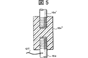
図5は、振動棒の電気的絶縁領域16e”の近傍を示す部分拡大断面図である。また、図6は電気的絶縁領域16e”の斜視図を示し、図7はその平面図を示す。
電気的絶縁領域16e”は、例えば合成樹脂またはゴムで形成することができる。電気的絶縁領域16e”は、振動棒を構成するものであるから、振動により破損せず、振動モータの振動を効率よく伝達でき、十分な絶縁性を発揮する材料を選択するのが好ましい。この様な観点から硬質ゴムが最も好ましい。その一例としては、硬質ポリウレタンゴムを挙げることができる。なお、このような絶縁材料のみからなる部材では強度的に不十分である場合には、絶縁性を損なわない範囲で、絶縁部材のみからなる部材の周囲などを例えば金属などで補強して、所要の機械的強度を得ることができる。
絶縁領域16e”は、具体的には、例えば、図示される様な硬質ゴム製の円柱状絶縁部材(多角形状等形状は任意)よりなり、その中央の上部分及び下部分に、振動棒上部分16e’及び振動棒下部分16eをそれぞれ嵌合させるための嵌合用穴124,125が設けられている。これらの嵌合用穴は上下には貫通しておらず、そのため、これら嵌合用穴の間の非貫通部分は絶縁部として機能する。
上下の嵌合用穴を貫通させた場合には、振動棒上部分16e’と振動棒下部分16eとが接触しないように、上記非貫通部分に対応する箇所に絶縁材料を充填するか、絶縁に十分な程度の空間を設ける。円柱状絶縁部材の嵌合用穴124,125は、振動棒上部分16e’と振動棒下部分16eの接合のために機能する。接合は、ネジ止め(たとえば、図示されている様に、振動棒上部分16e’の下端部と振動棒下部分16eの上端部とに雄ネジを切り、嵌合用穴124,125に雌ネジを切って、両者を結合させ、必要に応じて更にその上にワッシャーリングを当て、ビス止めする)でもよいし、接着剤による接合でもよい。いずれにしても、これらの部分の構造は、本発明の目的を達成できれば、その他のいかなる構造であってもよい。
たとえば、振動棒の直径が13mmの場合には、絶縁領域16e”は、長さ(高さ)Lが例えば100mmであり、外径r2が例えば40mmであり、嵌合用穴124,125の内径r2が13mmである。
図5及び図1に示されている様に、振動棒下部分16eの上部には、絶縁領域16e”の直下にて通電線127が接続されている。図1に示されている様に、通電線127は電源126に接続されており、該電源126には処理槽10Aと接続された通電線127が接続されている。振動棒下部分16e、固定部材16j及び振動羽根16fは導電性部材例えば金属からなり、更に処理槽10Aが導電性部材例えば金属からなる場合には、電源126から通電線127,128を介して振動羽根下部分16eと処理槽10Aとの間に印加された電圧に基づき、振動羽根下部分16e、固定部材16j及び振動羽根16fと処理槽10Aとの間で電流が流れる。これにより、振動撹拌下で被処理液14に対する処理がなされる。電源電圧は、所望の処理に応じて、交流電圧、直流電圧及びパルス状電圧のいずれかを使用することができる。電源電圧値は、所望の処理に応じて異なり例えば1〜15Vである。また、通電電流値も、所望の処理に応じて異なり例えば0.5〜100Aである。
なお、処理槽10A内に、通電線127と接続された電極部材を配置することも可能であり、これにより該電極と振動羽根下部分16e、固定部材16j及び振動羽根16fとの間で被処理液14に対する一層高い電流密度での通電を実現することができる。また、処理槽10A内に、本実施形態のものと同様なもう1つの振動撹拌装置を配置し、その振動棒下部分に通電線127を接続することで、2つの振動撹拌装置の振動羽根下部分16e、固定部材16j及び振動羽根16fどうしの間で被処理液14に対する通電を行なうことが可能である。被処理液14内での通電のための電極として該被処理液と接触する様に配置される対をなす電極部材(例えば、一方の電極として利用される振動羽根16fと他方の電極として利用される処理槽10A、あるいは専用の陽極部材と陰極部材)間の距離を例えば20〜400mmとしてもショートすることなく処理を行なうことができる。
この被処理液14に対する処理として、例えば、通電による殺菌処理が挙げられる。即ち、めっきにおいてめっき液から塩素イオンが除去されると、菌が繁殖しやすくなり、めっき液の劣化が早められるのであるが、通電によりこの様な菌の繁殖を避けることができる。また、飲料例えば水や牛乳、あるいは食器や野菜や果物等の洗浄水の殺菌に利用することができる。また、被処理液14に対する別の処理としては、例えば水を酸素と水素とに分解する電解処理が挙げられる。
この様な処理で使用される陽極材料としては、例えば、処理液が希薄塩化物(水溶液)等である場合には、Pt、Pt合金、Pt族金属、合金被覆を有するものが挙げられ、例えば、処理液が苛性アルカリ(水溶液)等である場合には、Ni、Ni合金、Fe、Fe合金、炭素鋼、ステンレス鋼等が挙げられる。
本実施形態においては、振動棒上部分16e’は絶縁領域16e”により振動棒下部分16eとは電気的に絶縁されているので、振動棒下部分16eを介する通電の影響が振動モータ16dへと及ぶことはない。更に、本実施形態では、絶縁領域16e”が熱絶縁性をも有するので、振動棒上部分16e”は振動棒下部分16eとは熱的にも絶縁され、処理液14の温度の影響が振動モータ16dへと及ぶことは少なく、処理液14が高温または低温のものであっても振動モータ16dが熱的影響により劣化するようなことがない。
また、本実施形態の装置において、絶縁式振動撹拌装置の振動羽根を電極として用いずに、別途、電源126に接続された電極部材を処理槽10A内に配置し、該電極部材を用いて被処理液14に対する通電を行なう場合においても、絶縁領域16e”が存在するので、被処理液14内の通電の影響が振動モータ16dへと及ぶことがないという利点がある。
図8は、本発明による絶縁式振動撹拌装置の他の実施形態の構成を示す側面図である。この実施形態は、振動棒下部分16eに、振動羽根16fの他にこれと交互に配置された電極用補助羽根16f’を取り付けたことのみ、図1の実施形態と異なる。電極用補助羽根16f’は、振動棒下部分16eと電気的に接続されていて、被処理液14に対する通電の際の一方の電極として機能し、従って振動撹拌の機能は必須ではない。電極用補助羽根16f’を使用する目的は電極面積の増加と当該電極と反対側の電極との間隔の低減とにあるので、電極用補助羽根16f’の大きさ(面積)は振動羽根16fより大きいほうが好ましく、また図示されている様に、補助羽根16f’の先端縁(右端縁)は振動羽根16fの先端縁(右端縁)より更に右方へと突出しているのが好ましい。
電極用補助羽根16f’は、振動羽根と振動羽根との中間に位置する様に振動棒に取り付けるのが好ましいが、必ずしもこれに限定されることはなく、振動撹拌の効果を著しく低減させない限りは、上下一方の振動羽根に近接して配置することも可能である。振動棒下部分16eへの電極用補助羽根16f’の取り付けは、振動羽根16fの取り付けと同様にして行なうことができる。
電極用補助羽根16f’の材質としては、電極として使用され得るものであればよいが、振動棒の振動に従って振動するものであるから、振動に耐え得ることが要求され、例えば振動羽根として使用可能な導電体例えば金属例えばチタン(表面に白金めっきを施すことができる)またはステンレス(表面に白金めっきを施すことができる)を使用することができる。尚、電極用補助羽根16f’を使用する場合には、振動羽根16fは必ずしも導電性材料からなる必要はなく、合成樹脂製のものを使用することも可能である。
図9及び図10は本発明による絶縁式振動撹拌装置を用いた液処理装置の他の実施形態の構成を示す断面図であり、図11は振動棒16eへの振動羽根16fの取り付け部の拡大断面図である。
本実施形態では、2つの振動棒にわたって各振動羽根が取り付けられている。図11に示されている様に、振動羽根16fの各々の上下両側には、振動羽根固定部材16jが配置されている。隣接する振動羽根16fどうしの間には固定部材16jを介して振動羽根16fの間隔設定のためのスペーサリング16kが配置されている。尚、最上部の振動羽根16fの上側及び最下部の振動羽根16fの下側には、図10に示されているように、スペーサリング16kを介して又は介することなく、振動棒下部分16eに形成されたオネジに適合するナット16mが配置されている。図11に示されているように、各振動羽根16fと固定部材16jとの間にフッ素系樹脂やフッ素系ゴムなどからなる振動応力分散手段としての弾性部材シート16pを介在させることで、振動羽根16fの破損を防止することができる。弾性部材シート16pは、振動羽根16fの破損防止効果を一層高めるために、固定部材16jから若干はみ出すように配置するのが好ましい。この様な弾性部材シート16pは、他の実施形態においても同様に使用することができる。振動棒下部分16eと振動羽根16とは電気的に接続されている。
図示されているように、上側の固定部材16jの下面(押圧面)は凸状面とされており、下側の固定部材16jの上面(押圧面)は対応する凹状面とされている。これにより、固定部材16jにより上下方向から押圧される振動羽根16fの部分は湾曲せしめられ、振動羽根16fの先端部は水平面に対して角度αをなしている。この角度αは、例えば−30°以上30°以下好ましくは−20°以上20°以下とすることができる。特に、角度αは、−30°以上−5°以下または5°以上30°以下、好ましくは−20°以上−10°以下または10°以上20°以下とするのが好ましい。固定部材16jの押圧面を平面とした場合には、角度αは0°である。角度αは、全ての振動羽根16fについて同一である必要はなく、例えば、下方の1〜2枚の振動羽根16fについては−の値(即ち下向き:図11に示される向き)とし、それ以外の振動羽根16fについては+の値(即ち上向き:図11に示されるものと逆の向き)とすることができる。尚、電極用補助羽根を使用する場合には、該補助羽根も振動羽根16fと同様にして上向きまたは下向きに適宜の角度傾けることができる。
図12は振動羽根16fの近傍を示す断面図である。振動羽根16fは固定部材16jからはみ出した部分が振動流動の発生に寄与するのであり、このはみ出した部分は幅D1で長さD2である。本実施形態では、複数の振動棒にわたって各振動羽根が取り付けられているので、各振動羽根の面積を十分大きくとることができる。かくして、大きな振動流動を得ることができ、また電極として使用される面積を大きくすることが可能である。
尚、本実施形態では、コイルバネ16b内に、基台16aに固定された下側棒状ガイド部材と振動部材16cに固定された上側棒状ガイド部材とが適宜の間隔をおいて配置されている。
本実施形態においては、図示はしないが、図1に関し説明した様な処理用電源126及び通電線128が使用される。
本実施形態においても、図8の実施形態と同様に、電極用補助羽根を使用することができる。
図13は本発明による絶縁式振動撹拌装置を用いた液処理装置の他の実施形態の構成を示す断面図である。本実施形態の振動撹拌装置16においては、振動モータ16dは、処理槽10A外に配置されていて、振動部材16cが処理槽10Aの方へと延びている。
本実施形態においても、図示はしないが、図1に関し説明した様な処理用電源126及び通電線128が使用される。
図14は本発明による絶縁式振動撹拌装置を用いた液処理装置の他の実施形態の構成を示す断面図である。本実施形態では、図13の実施形態と同様な振動モータ16d、振動部材16c、振動棒上部分16e’及び絶縁領域16e”の組が、処理槽14の両側に配置されている。そして、振動棒下部分16eは、コの字形状をなしており、その2つの垂直部分が2つの絶縁領域16e”にそれぞれ対応して配置されている。これら2つの垂直部分の上端がそれぞれ絶縁領域16e”を介して2つの振動棒上部分16e’にそれぞれ接続されている。振動羽根16fは、振動棒下部分16eの水平部分にほぼ垂直に取り付けられている。上記の様に、振動羽根16fは垂直方向に対して傾斜をもって配置されてもよいことは上記と同様である。
本実施形態においても、図示はしないが、図1に関し説明した様な処理用電源126及び通電線128が使用される。
図13の実施形態及び図14の実施形態においても、図8の実施形態と同様に、電極用補助羽根を使用することができる。
図15は本発明による絶縁式振動撹拌装置の変形例を示す部分拡大斜視図である。この変形例では、振動羽根16fのための固定部材16jとして光触媒活性を有する酸化チタン等からなる表面を有するものを用いており、しかも、その一部に強磁性体部材(磁石)16j’がはめ込まれている。従って、紫外線ランプ51から発せられる紫外光UVを固定部材16jに照射し、上記実施形態と同様にして振動棒16e、固定部材16j及び振動羽根16fを介して被処理液に通電しながら、該被処理液を振動撹拌する液処理装置を構成することで、強磁性体部材16j’の発する磁力による殺菌効果と、固定部材16jの光触媒活性に基づく殺菌効果と、通電による殺菌効果とを同時に発揮させ、しかも振動撹拌により被処理液を振動棒16e、固定部材16j、強磁性体部材16j’及び振動羽根16fに対して十分に供給して、被処理液の殺菌を極めて高い効率で実現することができる。
上記酸化チタン等からなる表面を形成するための手段としては、TiO2などの微粒子(粒径5μm以下)を含む複合電気めっき(コンポジットめっき)が挙げられる。この様な光触媒活性を有する表面は、固定部材16jのみならず、同様な殺菌処理を行なうための部材(たとえば振動羽根16fや後述の図34の実施形態における槽内配置部材61)にも同様に形成することができる。
本実施形態においても、図示はしないが、図1に関し説明した様な処理用電源126及び通電線128が使用される。
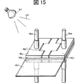
図34はこの様な液処理装置の変形例を示す部分斜視図である。この変形例においては、処理槽内に、光触媒活性を有する酸化チタン等からなる表面を有する複数の槽内配置部材61を保持部材60により固定して互いに平行に配置し、これら槽内配置部材61の隣接するもの同士により光ファイバ53を挟持している。光ファイバ53は、互いに平行に配置されており、その側面に粗面化などにより漏光部が形成されている。光ファイバ53の一端側には不図示の紫外光源から発せられる紫外光が導入される。これにより、光ファイバ漏光部から紫外光を槽内配置部材61に照射し、上記実施形態と同様にして振動棒16e、固定部材16j及び振動羽根16fを介して被処理液に通電し、槽内配置部材61の光触媒活性に基づく殺菌効果と、通電による殺菌効果とを同時に発揮させ、しかも振動撹拌により被処理液を振動棒16e、固定部材16j、及び振動羽根16f並びに槽内配置部材61に対して十分に供給して、被処理液の殺菌を極めて高い効率で実現することができる。尚、図では絶縁領域16e”や振動棒下部分16eに接続された通電線127や処理用電源126が示されていないが、これらは上記実施形態のものと同様にして設けられている。
この実施形態では、槽内配置部材61への紫外光照射が極く近くからなされるので、被処理液の紫外線透過性が低い場合(例えば被処理液が牛乳の場合)であっても高い殺菌効果が得られる。
尚、本発明の絶縁式振動撹拌装置を用いてはいないが、類似の殺菌処理については、本発明者の発明に係る日本国特許出願に関する特開2001−271189号公報及び特開2002−102323号公報に記載がある。
図16は本発明による絶縁式振動撹拌装置を用いた液処理装置の他の実施形態の構成を示す部分断面図であり、図17はその部分側面図である。
本実施形態では、2つの振動棒下部分16eを機械的に接続する様に取り付けられている振動羽根16e及び固定部材16jを2つの群に区分し、第1の群を一方の振動棒下部分16eと電気的に接続させ、第2の群を他方の振動棒下部分16eと電気的に接続させ、これら2つの群の間で電圧を印加することで、被処理液14に通電し所要の処理を行なう様にしている。
即ち、図16において、上側から奇数番目の振動羽根16f及び固定部材16jは、右側の振動棒下部分16とは電気的に接続されているが、左側の振動棒下部分16とは絶縁ブッシュ16s及び絶縁座金16tを介して取り付けられることで電気的に絶縁されている。一方、上側から偶数番目の振動羽根16f及び固定部材16jは、左側の振動棒下部分16とは電気的に接続されているが、右側の振動棒下部分16とは絶縁ブッシュ16s及び絶縁座金16tを介して取り付けられることで電気的に絶縁されている。かくして、上側から奇数番目の振動羽根16f及び固定部材16jを第1の群とし、上側から偶数番目の振動羽根16f及び固定部材16jを第2の群とし、左側の振動棒下部分16に接続されている通電線127と右側の振動棒下部分16に接続されている通電線127との間に不図示の処理用電源により所要の電圧を印加することで、第1の群と第2の群との間で被処理液14に通電することができる。尚、図17では絶縁ブッシュ16s及び絶縁座金16tの図示が省略されている。
本実施形態においては、絶縁領域16e”は振動棒16eと振動発生手段を構成する振動部材16cとの間に設けられている。即ち、ここでは、絶縁領域16e”が、上記実施形態における振動部材16cへの振動棒16eの取り付け部111の機能を兼ねている。
本実施形態においては、被処理液14への通電に直流電圧を用いる場合には、陽極側となる振動羽根16fはチタンの表面に白金めっきを施したものが好ましく用いられ、陰極側となる振動羽根16fはチタンが好ましく用いられる。
本実施形態によれば、振動撹拌装置に対する給電のみで液処理が可能となるので、装置をコンパクトなものとすることができる。また、振動羽根16fを2種類の電極のそれぞれとして兼用しているので、この点からも装置のコンパクト化がなされている。
図18は本発明による絶縁式振動撹拌装置を用いた液処理装置の他の実施形態の構成を示す部分側面図である。
本実施形態では、図16及び図17の実施形態における上側から偶数番目の振動羽根16fに代えて陽極部材16f”を使用している。この陽極部材16f”は、振動撹拌には寄与せず、図の右側にのみ延びている。陽極部材16f”としては、例えばチタン製ラス網(表面に白金めっきを施したもの)が好ましく用いられる。一方、上側から奇数番目の振動羽根16fに対してスペーサ16uを介して陰極部材16f”’を追加している。この陰極部材16f”’も、振動撹拌には寄与せず、図の右側にのみ延びている。陰極部材16f”’としては、例えばチタン板が好ましく用いられる。
本実施形態では、振動羽根16fとは別に電極部材としての陽極部材16f”及び陰極部材16f”’を使用しているので、電極材料の選択の自由度が増加する。
図19は本発明による絶縁式振動撹拌装置を用いた液処理装置の他の実施形態の構成を示す部分断面図である。
本実施形態では、2つの絶縁式振動撹拌装置が処理槽10A内に配置されており、一方の絶縁式振動撹拌装置の隣接する電極用補助羽根16f’どうしの間に他方の絶縁式振動撹拌装置の電極用補助羽根16f’が位置している。これにより、2つの絶縁式振動撹拌装置の一方を陽極側として使用し且つ他方を陽極側として使用することで、大面積の陽極と陰極とを互いに近接して配置することができ、電流密度を著しく向上させることができる。
本実施形態においては、2つの絶縁式振動撹拌装置の電極用補助羽根16f’どうしが接触してショートするのを防止するために、図20に示す様に、電極用補助羽根16f’の両面の外周部等を絶縁テープ16faなどの貼付により絶縁部とすることが好ましい。
図33は本発明による絶縁式振動撹拌装置の他の実施形態を示す部分断面図である。本実施形態では、絶縁領域16e”は熱絶縁領域として使用されている。振動棒下部分16eには、絶縁領域16e”の下側(即ち、絶縁領域16e”を基準として不図示の振動羽根を取り付けた部分の側)において、熱交換媒体注入部130及び熱交換媒体取出部132が設けられており、振動棒下部分16eにはこれら熱交換媒体の注入部130及び取出部132と連通する熱交換媒体通路131が形成されている。かくして、注入部130から通路131を通って取出部132へと熱交換媒体を流通させることで、被処理液が高温または低温の場合であっても、絶縁領域16e”の熱絶縁効果と相まって、熱的影響が振動モータを含む振動発生手段の方へと及ぶのを防止することができる。
尚、本実施形態の様に絶縁領域16e”により熱的絶縁を行なう場合には、電気的絶縁の場合に比べて絶縁領域16e”の寸法を大きくすることが好ましい。また、絶縁領域16e”の外面にヒレ状の放熱板を形成しておくことも可能である。また、被処理液が低温の場合には、上記通路131への熱交換媒体流通に代えて、振動棒下部分16eにヒーターを配置することも可能である。
次に、本発明による表面処理装置の実施形態を示すが、以下の具体的実施形態以外にも、以上の実施形態において液処理装置の被処理液を処理液とし且つ一方の電極部材を被処理品に置き換えることで、本発明の表面処理装置を構成することが可能である。
図21及び図22は本発明による絶縁式振動撹拌装置を用いた表面処理装置の一実施形態の構成を示す断面図である。
本実施形態では、処理槽10Aの左右両端部にそれぞれ絶縁式振動撹拌装置が配置されている。該絶縁式振動撹拌装置としては、上記実施形態において説明したものが使用され、特に電極用補助羽根16f’を備えたものが使用されている。処理槽10A内には、処理液14が収容されており、該処理液中に被処理品ARTが配置されている。該被処理品ARTは、保持手段80により吊下げられて保持されており、該保持手段80からの通電が可能とされている。
陽極酸化処理等の様に被処理品が陽極側とされる場合には、図示されている様に、保持手段80として陽極ブスバーが使用され、該陽極ブスバーは通電線128を介して処理用電源の陽極に接続されている。一方、該電源の陰極は、通電線127を介して上記2つの振動撹拌機の振動棒下部分16eと接続される。これに対して、めっき処理等の様に被処理品が陰極側とされる場合には、保持手段80として陰極ブスバーが使用され、該陰極ブスバーは通電線128を介して処理用電源の陰極に接続され、該電源の陽極が通電線127を介して上記2つの振動撹拌機の振動棒下部分16eと接続される。
処理用電源は、直流を発生するものであればよく、通常の平滑な直流でもよいが、その他の種々の波形の電流を使用することができる。例えば、エネルギー効率の向上の観点から、パルス波形のうちの矩形波パルス波形をのものを使用することが好ましい。この様な電源(電源装置)は、交流電圧から矩形波状電圧を作成することができるものであり、例えばトランジスタを用いた整流回路を有するものであり、パルス電源装置として知られている。このような電源装置または整流器としては、トランジスタ調整式電源、ドロッパー方式の電源、スイッチング電源、シリコン整流器、SCR型整流器、高周波型整流器、インバータデジタル制御方式の整流器(例えば(株)中央製作所製のPower Master)、(株)三社電機製作所製のKTSシリーズ、四国電機株式会社製のRCV電源、スイッチングレギュレータ式電源とトランジスタスイッチとからなりトランジスタスイッチがON−OFFすることで矩形波状のパルス電流を供給するもの、高周波スイッチング電源(交流をダイオードにて直流に変換した後にパワートランドスタで20〜30KHzの高周波をトランスに加えて再度整流、平滑化し出力を取り出す)、PR式整流器、高周波制御方式の高速パルスPR電源(例えばHiPRシリーズ((株)千代田)、サイリスタ逆並列接続方式のものなどが利用可能である。
ここで、電流波形について説明する。めっき或は陽極酸化の高速化とめっき被膜や陽極酸化膜の特性改良とを実現するためには、めっきや陽極酸化の電流波形の選択が重要である。電気めっき或は陽極酸化に必要な電圧・電流の条件は、めっきや陽極酸化の種類や処理液(浴)の組成や処理槽の寸法等によって異なり、一概には規定することができないが、例えばめっき電圧は直流の2〜15Vであれば全体を十分にカバーすることができる。そこで、めっき用電源の定格出力は6V、8V、12V、15Vの4種類が業界の標準になっている。この定格電圧以下の電圧は調整可能となっているので、めっきに必要な所望の電圧値に対して若干の余裕を見た定格電圧の電源を選択するのが好ましい。業界において、定格出力電流は500A、1000A、2000A〜10000A程度まで標準化されており、その他は注文生産の形態をとっている。被めっき処理品の所要電流密度×被めっき処理品のめっき面の表面積として、電源の所要電流容量を決定し、これに見合う適切な標準電源を選定することが得策である。
パルス波は、本来は幅が周期に比べて十分に短いものをいうが、この定義は厳密なものではない。また、パルス波には方形波以外のものも含む。パルス回路に用いる素子の動作速度が高くなり、パルス幅もns(10−9s)以下を扱える様になった。パルス幅が狭くなるにつれて前縁及び後縁の鋭い波形を維持するのが困難になる。これは、高い周波数成分を含んでいるからである。パルス波の種類としては、のこぎり波、ランプ波、三角波、複合波、矩形波(方形波)などがあるが、本発明の処理においては、特に電気の効率及び平滑性などから矩形波が好ましい。
パルスめっき処理用電源の一例としては、スイッチングレギュレータ式直流電源とトランジスタスイッチとを含み、トランジスタスイッチが高速でON−OFFすることにより、矩形波状のパルス電流を供給するものが挙げられる。
陽極酸化処理では、直流電解以外にパルス電解を使用することがある。電流反転法を利用したパルス電解は、高速化、膜質の向上、着色性の改良等多くの利点がある。
パルス電解用電源は、電流反転機能を有することが基本となるため、パルス電源2組を相互に逆極性となる様に接続したものとなる。しかし、この方式は、使用条件により効率が低下するので、パルスめっきに比して電源容量が大きいパルス電解に適用するには工業的には難点があり、むしろ3PR式整流器を転用する方が効率、価格、小形軽量等の点で実用性が高い。
サイリスタ逆並列接続方式のパルス電解波形は、サイリスタを逆並列接続したPR式整流器の原理を応用したもので、出力電圧波形は通常のサイリスタ整流器と同様となる。この場合の正常通電比は、波形のリップル周波数をパルス列にて電子制御するので、50Hz地域では約33ms、60Hz地域では約2.8ms単位で可変設定できる。
被処理品ARTは、電極用補助羽根16f’の先端縁から20〜400mmの距離に維持され、その被処理面である主表面(板状部材の両面)が電極用補助羽根16f’の先端縁と向かい合う様に配置されている。
本実施形態では、処理に際して、被処理品ARTを一方の電極とし、絶縁式振動撹拌装置の振動棒下部分16eやそれに電気的に結合している振動羽根16fや電極用補助羽根16f’を他方の電極として利用するので、振動羽根16fによる振動撹拌に基づく処理液14の流動により、電極表面にて発生または付着する各種ガスに起因する気泡が迅速に除去される。このため、電流効率が向上し、処理液の電気化学的反応が十分に促進される。
本実施形態の変形例としては、上記他方の電極として、更に別の電極部材(例えばめっき処理の場合にはめっきすべき金属よりなるもの)を併用することができる。この場合には、併用される電極部材を絶縁式振動撹拌装置と同一の極性になる様に電源に接続する。これにより、所要の電流量を確保しつつ、振動羽根や電極用補助羽根の寿命を長くすることができる。更に、その変形例として、絶縁式振動撹拌装置に代えて通常の振動撹拌装置を使用し(あるいは絶縁式振動撹拌装置の振動棒を電源と接続することなく)、上記他方の電極として専用の電極部材のみを使用してもよい。この様な変形は、以下の実施形態においても同様に可能である。
図23は本発明による絶縁式振動撹拌装置を用いた表面処理装置の他の実施形態の構成を示す平面図である。本実施形態は、例えば電着塗装処理に適用される。
図23において、処理槽10A内には、処理液14として液状電着塗料が収容されている。処理槽10A上には、吊下げコンベアからなる被処理品保持手段80が配置されており、該保持手段80を構成するハンガーには自動車部品等の被処理品ARTが吊下げられている。該被処理品ARTは、処理槽10A内で処理液14中に浸漬される。処理槽10A内には、被処理品ARTの移動経路の両側に、上記実施形態で説明したものと同様な絶縁式振動撹拌装置16が配置されている。本実施形態では、被処理品ARTの寸法に対応して、片側に2台の絶縁式振動撹拌装置16が配列されている。即ち、本実施形態は、上記図21及び図22の実施形態の装置が処理槽を共通にして2台配置されたものと同等である。
電着塗装処理用の電源により、保持手段80のハンガーと絶縁式振動撹拌装置16との間に電圧を印加し、電着塗装を行なう。非処理品ARTは、電極用補助羽根16f’の先端縁から20〜400mmの距離に維持される。
図24は本発明による絶縁式振動撹拌装置を用いた表面処理装置の他の実施形態の構成を示す平面図である。本実施形態は、例えば電着塗装処理に適用される。本実施形態は、基本的には図21及び図22の実施形態のものと同様である(被処理品ARTに印加する電圧の極性のみ異なる様に図示されているが、この極性は処理の内容に応じて適宜設定されるものである)。電着塗装処理では、カチオン電着塗装及びアニオン電着塗装に応じて、被処理品ARTに印加する電圧の極性が異なる。本発明では、特に絶縁式振動撹拌装置16を陽極側として使用するカチオン電着塗装に好適である。
図25は本発明による絶縁式振動撹拌装置を用いた表面処理装置の他の実施形態の構成を示す平面図である。本実施形態は、例えば電着塗装処理に適用される。
本実施形態は、図24の実施形態に、更に絶縁式振動撹拌装置16と同一の極性の電圧が印加される電極部材84の保持手段82を追加したものに相当する。被処理品ARTの保持手段80は例えば陰極ブスバーであり、電極部材84の保持手段82は例えば陽極ブスバーであり、電極部材84は例えばチタン製ラス網電極部材(表面に白金めっきを施したものが好ましい)である。図26にラス網電極部材の正面図を示す。上部に吊下げ用の孔が2つ設けられており、中央部から下部にかけて網状部とされており、この網状部が処理液中に浸漬される。電極部材84は、被処理品ARTと平行に且つ該被処理品ARTと絶縁式振動撹拌装置16との間に配置されている。
図27は振動撹拌装置を用いた表面処理装置の参考例の構成を示す平面図である。この参考例では、振動撹拌装置16は絶縁式のものではなく、被処理品ART及び電極部材85は、互いに平行に配置されているが、振動撹拌装置16に対して向き合う様には配置されていない。
図28は本発明による絶縁式振動撹拌装置を用いた表面処理装置の他の実施形態の構成を示す断面図である。本実施形態は、例えば陽極酸化処理に適用される。本実施形態は、基本的には図21及び図22の実施形態のものに、更に絶縁式振動撹拌装置16と同一の極性の電圧が印加される電極部材84の保持手段82を追加したものに相当する。但し、電極用補助羽根は使用されていない。被処理品ARTの保持手段80は例えば陽極ブスバーであり、電極部材84の保持手段82は例えば陰極ブスバーであり、電極部材84は例えばチタン製ラス網電極部材である。
図29及び図30は本発明による絶縁式振動撹拌装置を用いた表面処理装置の他の実施形態の構成を示す断面図である。本実施形態は、例えば電鋳めっき処理に適用される。本実施形態は、基本的には図25の実施形態の被処理品ARTの右側に位置する絶縁式振動撹拌装置及び電極部材を除去したものに相当する。但し、電極用補助羽根は使用されていない。そして、電極部材86として、図31に示される円柱状チタン網ケース内に複数の金属製ボール(ニッケルボール、銅ボールなど)を充填したものを使用し、これを水平方向に保持したものを用いている。
図32は本発明による絶縁式振動撹拌装置を用いた表面処理装置の他の実施形態の構成を示す断面図である。本実施形態は、例えばめっき処理に適用される。本実施形態は、基本的には図25の実施形態と同等である。但し、電極部材86として、図29及び図30の実施形態と同様なものを用いている。
尚、上記の様に、図1、図9、図13及び図14のそれぞれに関し説明した液処理装置において、保持手段により保持された被処理品を通電線128に接続し、該被処理品を一方の電極として利用し、これを処理液14内に浸漬することで、これら実施形態の液処理装置を被処理品の表面処理装置として使用することが可能である。
以下、実施例を挙げて本発明を説明するが、本発明はこれらにより何ら限定されるものではない。
[実施例1](牛乳殺菌)
図34に関し説明した液処理装置を用いて、牛乳の殺菌処理を行なった。処理条件は次のとおりであった:
絶縁式振動撹拌装置:
図16及び図17に関し説明したものを図34の槽内配置部材61の
両側に配置
振動モータ:200V(3相)×150W
振動周波数:42Hz
振動羽根:陰極側はチタン
陽極側はチタンの表面に白金めっきしたもの
処理用通電電源電圧:4.5V
処理用通電電流:3.5A
処理槽:W300×L700×H350mm
被処理液:
大腸菌をトリプチケースイソブロス培地にて、35℃で24時間培養
し、培養後の菌体懸濁液を処理槽内の60リットルの牛乳に懸濁した
もの[牛乳1ミリリットル当たり22,000の大腸菌を含む]
紫外線照射、通電及び振動撹拌を行なったところ、次の表1に示す様な結果が得られた。

[実施例2](電着塗装)
図23に関し説明した表面処理装置(電着塗装装置)における絶縁式振動撹拌装置16として、図21及び図22に関し説明した絶縁式振動撹拌装置を使用して、自動車部品のカチオン電着塗装を行なった。
処理槽(電着槽)10Aとして、鉄製で内面に合成樹脂ライニングの施されたタンクを使用し、その中に、合成樹脂水性エマルジョン、顔料ペースト、水などを含む処理液(液状電着塗料)14を入れ、電着槽中に電気的に絶縁された吊下げコンベア80にマイナス極のハンガーを掛け、これに自動車部品(被処理品ART)を吊下げて、これらをもマイナス極とする。絶縁式振動撹拌装置は、図21及び図22に示す様に、2本の振動棒と、白金めっきされたチタン製の振動羽根(厚さ0.5mm、図12に示すD1=250mm/D2=55mm、図11に示す傾き角α=15°)及び白金めっきされたチタン製の電極用補助羽根(厚さ0.5mm、図12に示すD1=250mm/D2=150mmに相当、図11に示す傾き角α=15°)をプラス極に接続し、インバーターにより振動モータを45Hzで振動させ、振動羽根を振幅2mm、振動数1500回/分で振動させた。絶縁式振動撹拌装置16の配置は、図23に示す通りであり、被処理品ARTを挟んで2台づつ向かい合った形で4台用いた。
絶縁式振動撹拌装置は、振動モータとして200V(3相)×250Wのものを用い、振動棒の電気的絶縁領域には、図5〜図7に関し説明したような硬質ポリウレタン製の円柱状絶縁部材を用いた。この円柱状絶縁部材の図7に示すr1=16mm、r2=50mmとし、図6に示すL=100mmとした。
振動棒への通電は、インバータを介して250V、電流密度20A/dm2とした。電極用補助羽根の先端縁と自動車部品との最短間隔を100mmとし、自動車部品の液状電着塗料への浸漬時間を3分間とした。
その結果、約40μmの電着塗膜が得られた。
これに対して、比較例として、振動棒に通電を行なわず、且つ自動車部品からの距離が振動棒までとほぼ同様となる位置に極板を4組配置し、該極板を介して通電し、更に、振動撹拌装置を駆動させて電着塗装を行なったところ、浸漬時間6分間で、塗膜厚20μmとなった。
従って、振動棒に通電することにより、電着時間が約1/4に短縮されたことが分かる。
[実施例3](電着塗装)
実施例2の絶縁式振動撹拌装置として、電極用補助羽根のないものであって、振動羽根として厚さ0.5mm、図12に示すD1=250mm/D2=170mm、図11に示す傾き角α=15°のものを使用し、且つ全ての絶縁式振動撹拌装置と自動車部品との間に図26に関し説明した様な白金めっきされたチタン製のラス網電極板(電極部材)を挿入し、該電極板を振動撹拌装置の振動棒及び振動羽根と同一極性の陽極とした。振動羽根の先端縁とラス網電極板との間の距離を50mmとし、ラス網電極板と自動車部品との最短距離を100mmとした。即ち、絶縁式振動撹拌装置とラス網電極板と被処理品との位置関係は、図28に示すものと同様であった。
このように、電極用補助羽根を設ける代わりに、同一極性とされる電極板を設けることで、実施例2と類似の結果が得られた。
[実施例4](電着塗装)
実施例3と同様の絶縁式振動撹拌装置を使用し、図23に関し説明した表面処理装置(電着塗装装置)において、自動車部品のアニオン電着塗装を行なった。
鉄製タンクからなる電着槽内に、アマニ油とマレイン酸との共重合体をエタノールアミンで中和し、これに水、水溶性溶媒であるセロソルブアセテートブチレートを加え、不揮発分10%に調整したアニオン電着塗料を入れ、自動車部品を陽極として吊下げコンベアに吊下げ、電着槽を陽極、絶縁式振動撹拌装置を陰極とし、陰極とされている絶縁式振動撹拌装置の振動羽根先端縁と陽極とされている自動車部品との間隔を100mmとした。更に、絶縁式振動撹拌装置の自動車部品とは反対の側にチタン製ラス網電極板(図26参照:厚さ3.0mm、網状部厚さ1.5mm、網目の一方の対角線長10mm、他方の対角線長20mm)を設け、絶縁式振動撹拌装置の振動羽根後端とラス網電極板との間隔を50mmとし(即ち、自動車部品と向き合っている振動羽根先端とは反対側の端部とラス網電極板との距離を50mmとし)、ラス網電極板と電着槽との間隔を100mmとした。
振動撹拌装置の振動モータをインバーターにより45Hzで駆動させ、振動羽根を振幅2mm、振動数1800回/分で振動させ、処理用電源により陽極と陰極との間に直流200Vを印加して常温で電着塗装を行なった。この際、第1段階は10A/dm2の電流密度で1分間、第2段階は15A/dm2の電流密度で1分間の電着塗装とした。こうして得られた電着塗装品を、水洗後、160℃で焼き付け処理したところ、厚さ30μmの防錆性に優れた電着塗膜が得られた。
[実施例5](電着塗装)
実施例4では自動車部品−絶縁式振動撹拌装置−チタン製ラス網電極板−電着槽という配置であったが、本実施例では、自動車部品−ステンレス製金網電極板(電極部材)−絶縁式振動撹拌装置−電解槽という配置とし、自動車部品とステンレス製金網電極板との間隔を100mmとし、ステンレス製金網電極板と振動羽根前端縁との間隔を50mmとし、振動羽根後端縁と電解槽との間隔を100mmとした。
その結果、実施例4よりは僅かに劣るものの、ほぼ満足すべき結果が得られた。
[実施例6](電着塗装)
図14に示す絶縁式振動撹拌装置を使用した。被処理品としての小物部品を細長い回転かご(合成樹脂バレル)に入れ、かごの細長い周面が振動羽根と向かい合うような配置とした。振動羽根と回転かごとの距離を100mmとした。振動羽根としては、ステンレス製で、厚さ0.5mmで、図12に示すD1=250mm/D2=170mmのものを用いた。
電着槽に、アルキッド樹脂系水性樹脂エマルジョン、顔料ペースト、水などを含む液状電着塗料を入れ、回転かご内部の被処理品を陰極とし、振動羽根を陽極として、カチオン電着塗装を行なった。処理に当たっての電流密度は15A/dm2であった。
これにより、小物部品に迅速且つ均一で不良のない電着塗装が達成できた。
[実施例7](電着塗装)
1m角の鋼板に対して、以下の(1)〜(4)の工程よりなる前処理を行なった:
(1)脱脂:振動撹拌装置(振動モータ振動数40Hz)を使用し、50〜6
0℃の弱アルカリ性脱脂剤液を用いて2分間処理
(2)水洗:振動撹拌装置(振動モータ振動数40Hz)を使用し、40〜5
0℃の水を用いて2分間処理
(3)純水洗:5×10⁵Ω以上の常温の脱イオン水を用いて2分間処理
(4)水切・空気乾燥:130〜140℃で5分間処理
得られた前処理済の鋼板に対して、以下の電着塗装を行なった:
電着槽:鉄製ライニング槽(液量600リットル)
電着塗料:エポキシアダクトの第4級アミンで中和した水性プライマータイプエマルジョン塗料
液温:30℃
振動撹拌装置の種類と配置:
(イ)200V(3相)×150Wの絶縁式振動撹拌装置(振動羽根[白金めっきされたチタン製]と電極用補助羽根[白金めっきされたチタン製])と被処理品とを、図25に示す配置とし、電極用補助羽根の先端縁と被処理品である鋼板との距離を100mmとした。被処理品を陰極とし、絶縁式振動撹拌装置の振動羽根と電極用補助羽根とを陽極とし、整流器を用いて150Vの電圧をかけ、電流密度を30A/dm2とした。
(ロ)前記(イ)の絶縁式振動撹拌装置と被処理品との間に、図25に示す様に、白金めっきされたチタン製ラス網電極板(図26のもの)を配置した。被処理品である鋼板とラス網電極板との距離は100mm、ラス網電極板と絶縁式振動撹拌装置の電極用補助羽根先端縁との距離は50mmとした。そして被処理品を陰極とし、ラス網電極板と振動羽根及び電極用補助羽根とを陽極とし、整流器を用いて150Vの電圧をかけ、電流密度を30A/dm2とした。
(ハ)比較のために示す。被処理品、電極部材及び振動撹拌装置を図27の様に配置した。この配置では、被処理品である鋼板と電極部材とは互いに向き合っているが、振動撹拌装置の振動羽根に対しては被処理品と電極部材とはいずれも向き合った関係にはなく、直角となるように配置されている。従来タイプの振動撹拌は、液体をできるだけ効率よく撹拌することが第1と考えられていたから、被処理品に振動羽根を近付けることや、振動羽根を被処理品と向き合った状態に置くという発想はなく、被処理品から出来るだけ離れた位置に振動撹拌装置を配置し、被処理品や電極部材は、液体の流れをできるだけ妨げない様に、振動羽根に対して直角に配置していたのである。この配置では、電極部材は(イ)及び(ロ)と異なり金網状である必要はない。また、振動撹拌装置は、絶縁式である必要はない。ここでは、被処理品と電極部材との距離を400mmとし、振動羽根として、ステンレス製で、厚さ0.4mmで、図12に示すD1=180mm/D2=50mm(図4の第1回目のピークを示す長さ)のものを用いた。被処理品を陰極とし、電極部材を陽極とし、150Vの電圧をかけ、電流密度を3A/dm2とした。
以上の(イ)、(ロ)及び(ハ)の各システムを用いて液温30℃で電着塗装を行なった。得られた試験板の電着塗装結果を、以下の表2に示す。尚、電着塗装の前処理及び後処理においても、振動撹拌機を使用した。
一般に、陽極酸化処理は、その前処理工程や後処理工程に比較して時間がかかりすぎるという問題があった。
そこで、この実施例8では、図21及び図22に示す装置を使用した。
ここで使用した絶縁式振動撹拌装置は、下記のものである。
振動モータ:200V(3相)×150W
振動周波数:50Hz
振動羽根:チタン製で、厚さ0.4mmで、図12に示すD1=180m
m/D2=150mm(図4の第2回目のピークを示す長さ)
のもの6枚
電極用補助羽根:チタン製のもの5枚
また、被処理品として、アルミニウム(#2017)製で、寸法100×100×2mmのものを用いた。使用薬として硫酸(200g/リットル)を用いて処理液を調製し、一般アルマイト[実施例7−1]及び硬質アルマイト[実施例7−2]を形成した。
比較例として、絶縁式ではない従来の振動撹拌装置を使用し、電極部材を別途配置して、図27に示す様な配置を形成して、一般アルマイト及び硬質アルマイトを形成した。
以下の表3及び表4に、陽極酸化処理条件及び得られた結果を示す。
本実施例では、図28に示す装置を使用した。ここで、陽極酸化対象金属(被処理品)としては、寸法100×100×2mmのアルミニウム板(#2017)を用い、これに向き合った形でその両側にチタン製ラス網電極板を配置し、更に、その両側に向かい合う様にして絶縁式振動撹拌装置を配置した。振動羽根は、チタン製で、厚さ0.4mmで、図12に示すD1=180mm/D2=50mm(図4の第1回目のピークを示す長さ)のもの6枚とした。振動羽根とチタン製ラス網電極板との間隔は50mm、チタン製ラス網電極板とアルミニウム板との間隔を100mmとした。
絶縁式振動撹拌装置を介する通電を行なわずに、振動モータを40Hzで駆動し、振動羽根を振幅1.5mmで、振動数2000回/分で振動させ、使用薬として硫酸(200g/リットル)を用いて処理液を調製し、一般アルマイト及び硬質アルマイトを形成した。
その結果、実施例7と比較するとやや劣るが、それでもマイクロポーラスがなく、ほぼ均一なアルマイトが得られた。
陽極酸化処理条件及び得られた結果は、次のとおりであった:
(その1)一般アルマイト
電圧:19V
電流密度:20A/dm2
温度:21℃
処理時間:3分
膜厚:16μm
(その2)硬質アルマイト
電圧:21V
電流密度:20A/dm2
温度:5℃
処理時間:3分
膜厚:16μm
[実施例10](陽極酸化)
絶縁式振動撹拌装置を介する通電を行なうこと以外は、実施例9と同様な処理を行なった。但し、振動羽根の振動数を1800回/分とし、電流密度を30A/dm2とした。
その結果は、実施例9とほぼ同一であった。
[実施例11](マグネシウムの陽極酸化)
陽極酸化対象物(被処理品)として、マグネシウム合金AZ91Dからなるものを用い、予備処理/アルカリ浸漬洗浄/水洗(/アルカリ陽極電解洗浄/水洗)/酸洗い(中和)/水洗/酸処理/水洗/陽極酸化処理/水洗/乾燥の工程を経て、製品とした。
酸処理に用いる処理浴は、85%リン酸50g/リットルで、使用温度は21℃であった。陽極酸化処理に用いる処理浴の組成は、
水酸化カリウム 200g/リットル
リン酸ナトリウム 50g/リットル
水酸化アルミニウム 50g/リットル
であった。
実施例8と同様に図21及び図22に示す装置を用いて陽極酸化処理を行なった。
比較例として、実施例11と同一の陽極酸化対象物に対して、250Vの火花放電により陽極酸化を行なった。
以下の表5に、陽極酸化処理条件及び得られた結果を示す。
陽極酸化処理浴の組成を、
水酸化カリウム 165g/リットル
フッ化カリウム 35g/リットル
リン酸ナトリウム 35g/リットル
水酸化アルミニウム 35g/リットル
過マンガン酸カリウム 20g/リットル
としたこと以外は、実施例11と同様の工程を実施した。その結果、実施例11と同様な結果が得られた。
[実施例13](電鋳めっき)
図29〜30に関し説明した装置を用いて、直径200mmで厚さ2mmの光ディスク用SUS円板の電鋳めっきを行なった。絶縁式振動撹拌装置は、振動モータが200V(3相)×250Wで、振動羽根がチタン製で、厚さ0.5mm、図12に示すD1=250mm/D2=55mm(図4の第1回目のピークを示す長さ)であった。電極部材のチタン網ケース内には直径25mmのニッケルボールを多数詰めたものを用いた。振動羽根とチタン網ケースとの距離を50mmとし、チタン網ケースと被処理品との距離を100mmとした。振動モータを50Hzで駆動し、振動羽根を振幅2mm、振動数3100回/分で振動させた。
処理液としてスルファミン酸ニッケル浴を用いて、下記の要領で電鋳めっきを行なった。
(1)スルファミン酸ニッケル浴の組成
スルファミン酸ニッケル結晶 600g/リットル
塩化ニッケル 5g/リットル
ホウ酸 40g/リットル
応力調整剤(ナフタリントリスルホン酸ソーダ)
0.5〜3ミリリットル/リットル
ピット防止剤(ラウリル硫酸ナトリウム)
2〜3ミリリットル/リットル
(2)処理温度 50℃
(3)処理時間 30分
(4)電流密度 60A/dm2
(5)電圧 17V
(6)pH 4.5
比較のために、絶縁式でないことを除いて同等の振動撹拌装置を備えた図27に関し説明した装置を用いて電鋳めっきを行なった。
以下の表6に、処理条件及び得られた結果を示す。
[実施例14](めっき)
図32に関し説明しためっき装置を用いて、100×100×1.5mmの前処理及び導電化処理済のエポキシ樹脂製プリント基板(被処理品)の銅めっき(特に50μmのスルーホールへのめっき)を行なった。
絶縁式振動撹拌装置は、振動モータが200V(3相)×150Wで、振動羽根がチタン製で、厚さ0.4mm、図12に示すD1=180mm/D2=50mm(図4の第1回目のピークを示す長さ)5枚であった。電極部材の250mm×30mmφのチタン網ケース内に含リン銅製ボール8個を入れたものを横向きにして上下に4本並べてセットした。振動羽根とチタン網ケースとの距離を50mmとし、チタン網ケースと被処理品との距離を50mmとした。
振動モータを50Hzで駆動し、振動羽根を振幅2mm、振動数3000回/分で振動させ、めっき槽(725×400×450mm)中で、下記の要領でめっきを行なった。
(1)めっき液の組成
硫酸 190g/リットル
硫酸銅五水和物 70g/リットル
添加剤(光沢剤) 5ミリリットル/リットル
(2)処理条件
めっき浴液温 25℃
電流密度 30A/dm2
処理時間 5分
比較のために、絶縁式でないことを除いて同等の振動撹拌装置を備えた図27に関し説明した装置を用いてめっきを行なった。
以下の表7に、処理条件及び得られた結果を示す。
図21に関し説明した装置(但し、図21に示されているものとは極性が異なる)を用いて、プリント基板の銅めっきを行なった。絶縁式振動撹拌装置は、電極用補助羽根を有することを除いて実施例14のものと同様のものを使用した。電極用補助羽根は、図12のD1に対応する寸法が振動羽根と同一であるが、図12のD2に対応する寸法が振動羽根の2倍となる様にした。電極用補助羽根の枚数は5枚とした。
それ以外は実施例14と同様にして実施した。めっき液は適宜補充した。
めっきの速さ及び仕上り状態は実施例14とほぼ同一であったが、スルーホールへのめっきは実施例14より優れていた。
[実施例16](めっき)
実施例15において、直流8Vの適用を、周波数1kHzの5%パルス電源を使用して実施した。直径20μmのスルーホール部分のめっきが実施例1より一層きれいに、均一に且つ長時間にわたって安定して実施可能であった。
産業上の利用可能性
(1)振動撹拌装置の振動棒またはそれと振動発生手段との間に絶縁領域を設けることにより、振動撹拌装置の新しい利用分野が開拓された。
(2)絶縁領域を熱的絶縁領域とすることにより、高温または低温の処理液の撹拌にも振動撹拌装置を使用することができる様になった。
(3)絶縁領域を電気的絶縁領域とすることにより、振動撹拌装置の振動棒や振動羽根及び必要に応じて付設された電極用補助羽根に通電できるので、通電による被処理液の処理や通電による被処理物品の表面処理において振動撹拌の機能と通電のための少なくとも一方の電極としての機能とを持つ振動撹拌装置が提供された。
(4)通電による被処理物品の表面処理に本発明の振動撹拌装置を用いると、被処理品とその逆極性の電極との間の距離を短くして電流を流しても、ショートすることがなく、また被処理品または電極から泡が発生することがないため、従来より大きな電流密度で安定に高速処理することが可能となり、表面処理の効率を著しく向上させることができた。例えば、めっきの場合には従来3A/dm2程度であった電流密度を20〜30dm2程度に、電鋳めっきの場合には従来30A/dm2程度であった電流密度を60dm2程度に、陽極酸化の場合には従来3A/dm2程度であった電流密度を30dm2程度に、それぞれ向上させることができた。
(5)特に、被処理品とは逆極性の電極として利用される電極用補助羽根を付設した場合には、該電極用補助羽根の先端縁を一層被処理品に近付けることができるので、より大きな電流密度を容易に実現することができた。
(6)本発明の表面処理によれば、得られる表面の特性を著しく優れたものとすることができた。特に、形成された膜の厚さが均一であり、膜質特性も優れたものとなった。
(7)めっきの場合には、本発明を適用すると、従来法に比べて短時間でめっきができるだけでなく、被処理品に析出する金属の膜厚が細かくそろうことにより、ピットがなく均一な平滑面(レベリング)を形成することができた。
(8)電着塗装の場合には、本発明を適用すると、凹凸のある複雑な形状の部品の電着においても凹部と凸部との膜厚に差の少ない均一な電着膜を形成することができた。
(9)アルミニウムやマグネシウム等の軽金属の陽極酸化の場合には、本発明を適用すると、処理時間を大幅に短縮して生産性を格段に向上させ、且つ飛躍的に膜の硬度を高めると同時にマイクロポーラスがない高品質の製品が得られた。
【図面の簡単な説明】
図1は、本発明による絶縁式振動撹拌装置を用いた液処理装置の断面図である。
図2は、振動部材への振動棒の取り付け部の拡大断面図である。
図3は、振動部材への振動棒の取り付け部の拡大断面図である。
図4は、振動羽根の長さとしなりの程度との関係を示す図である。
図5は、振動棒の電気的絶縁領域の近傍を示す部分拡大断面図である。
図6は、振動棒の電気的絶縁領域の斜視図である。
図7は、振動棒の電気的絶縁領域の平面図である。
図8は、本発明による絶縁式振動撹拌装置の側面図である。
図9は、本発明による絶縁式振動撹拌装置を用いた液処理装置の断面図である。
図10は、本発明による絶縁式振動撹拌装置を用いた液処理装置の断面図である。
図11は、振動棒への振動羽根の取り付け部の拡大断面図である。
図12は、振動羽根の近傍を示す断面図である。
図13は、本発明による絶縁式振動撹拌装置を用いた液処理装置の断面図である。
図14は、本発明による絶縁式振動撹拌装置を用いた液処理装置の断面図である。
図15は、本発明による絶縁式振動撹拌装置の部分拡大斜視図である。
図16は、本発明による絶縁式振動撹拌装置を用いた液処理装置の部分断面図である。
図17は、本発明による絶縁式振動撹拌装置を用いた液処理装置の部分側面図である。
図18は、本発明による絶縁式振動撹拌装置を用いた液処理装置の部分側面図である。
図19は、本発明による絶縁式振動撹拌装置を用いた液処理装置の部分断面図である。
図20は、電極用補助羽根を示す図である。
図21は、本発明による絶縁式振動撹拌装置を用いた表面処理装置の断面図である。
図22は、本発明による絶縁式振動撹拌装置を用いた表面処理装置の断面図である。
図23は、本発明による絶縁式振動撹拌装置を用いた表面処理装置の平面図である。
図24は、本発明による絶縁式振動撹拌装置を用いた表面処理装置の平面図である。
図25は、本発明による絶縁式振動撹拌装置を用いた表面処理装置の平面図である。
図26は、電極部材の正面図である。
図27は、振動撹拌装置を用いた表面処理装置の参考例の構成を示す平面図である。
図28は、本発明による絶縁式振動撹拌装置を用いた表面処理装置の断面図である。
図29は、本発明による絶縁式振動撹拌装置を用いた表面処理装置の断面図である。
図30は、本発明による絶縁式振動撹拌装置を用いた表面処理装置の断面図である。
図31は、電極部材を構成する円柱状チタン網ケースの斜視図である。
図32は、本発明による絶縁式振動撹拌装置を用いた表面処理装置の断面図である。
図33は、本発明による絶縁式振動撹拌装置を示す部分断面図である。
図34は、本発明による絶縁式振動撹拌装置を用いた液処理装置の部分斜視図である。 Technical field
The present invention relates to a novel vibration stirrer having both a function as an electrode and a function as a cooling means, and an apparatus and method for processing a liquid to be processed or a product to be processed using the vibration stirrer. The present invention is suitable for performing surface treatment of various products to be treated, for example, by electrolysis.
Background art
The vibration stirrer is a device that attaches a vibrating blade to a vibrating rod and vibrates the vibrating rod, thereby causing the vibrating blade to flutter in a fluid such as a liquid, thereby causing the fluid to flow. The stirring device is described in, for example, the following patent documents relating to the Japanese patent application relating to the inventors' invention:
JP-A-3-275130 (Japanese Patent No. 1941498),
JP-A-6-220697 (Patent No. 2707530),
JP-A-6-312124 (Japanese Patent No. 2762388),
JP-A-8-281272 (Patent No. 2767777),
JP-A-8-173785 (Patent No. 2852878)
JP-A-7-126896 (Patent No. 2911350),
JP-A-11-189880 (Patent No. 29898624),
Japanese Patent Laid-Open No. 7-54192 (Patent No. 2998440),
JP-A-6-33035 (Patent No. 2992177),
JP-A-6-287799 (Patent No. 3035114),
JP-A-6-280035 (Japanese Patent No. 3244334),
JP-A-6-304461 (Patent No. 3142417),
JP 10-43569 A,
JP-A-10-369453,
Japanese Patent Application Laid-Open No. 11-253782.
The vibration stirrer is used for various processes, and its basic function is to generate a vibration flow in the fluid. In recent years, therefore, attempts have been made to impart functions other than the above basic functions to the vibration agitator.
For example, Japanese Patent Laid-Open No. 8-199400 uses an electrode made of titanium or a titanium alloy having a vane plate that can generate liquid flow accompanied by vibration of an electrolyte by vibrating up and down. An invention relating to an electrolytic polishing method for aluminum parts is disclosed. However, in this publication, whether a vibrating vibrating bar is used as an electrode or a vane plate is used as an electrode, and an electrical circuit between a part used as an electrode and other parts is used. There is almost no specific description of how insulation is maintained. From the whole description of this publication, it seems that the vibrating rod is used as an electrode. How is the insulation with the vibrating motor maintained when a current is passed through the vibrating rod, and how is the safety? There is no description or suggestion about whether it is.
Japanese Patent Application Laid-Open No. 9-125294 proposes a surface treatment apparatus that uses a support rod that seems to be a vibration stirrer as an electrode. Here, the electrical insulation between the vibration stirrer body and the electrode is also proposed. There is no description or suggestion of what to do. In the technique described in this publication, the current density is about 3 mA / cm, which is the same as the current density in normal plating.2It is said that.
Further, when high-temperature or low-temperature fluid is vibrated and agitated by the vibration agitator, heat is transferred between the fluid and the vibration generating means such as a vibration motor through the vibration rod, and the vibration generating means is affected by the thermal effect of the fluid. May reduce the performance.
Therefore, the present invention aims to expand the application area by adding functions other than the basic functions to the vibration agitator, and to improve the performance specific to the application area. To do.
One such application area is surface treatment. This surface treatment has the following technical problems.
In the technical fields such as anodic oxidation, plating and electrodeposition coating using today's electrolysis, the current density varies depending on the type, purpose or accessory of the treatment solution (electrolyte), but usually 2 to 3A. / Dm2Degree. The deposition rate of electroplating is proportional to the current density. Therefore, in order to perform high-speed plating, there is known a means for increasing the current density by injecting an electrolytic solution onto the object to be processed using a powerful pump or the like, but the current density is still 5 to 6 A / dm at most.2However, since the film thickness varies in the obtained product, it is hardly put into practical use.
Usually, in the region where the current density is low, the current efficiency is almost 100%. However, when the current density exceeds a certain level, the current efficiency decreases sharply, and generation of hydrogen gas from the plating surface is recognized. When the current density is increased, the pH of the electrode interface increases, and undesirable side reactions may occur on the electrode surface, or bubbles may be generated and the current may not flow, and the reaction may not proceed.
In this way, the current density has an upper limit, that is, the limit current density, and even if the current density is further increased to reduce the distance between the electrodes and increase the processing speed, burns and burns may occur in the product. Therefore, a smooth and uniform electrodeposition surface cannot be obtained.
Further, in the field of electroforming, the current density is 30 A / cm even by a so-called high-speed electroforming plating method.2The degree is the limit, and the film thickness varies about ± 8 to 10 μm.
In any of the surface treatments, a stirrer is disposed based on the idea that the treatment liquid can be uniformly stirred if it is not too close to the workpiece. This concept is followed even when a vibration stirrer is used, and there is no concept of reducing the distance between the stirrer and the article to be processed or the distance between the stirrer and the electrode. That is, the product to be treated is not placed at a position facing the vibration stirrer, and one end of the anode is located far away from the vibration stirrer, and the stirrer stirs the entire processing liquid. It is an arrangement considering only the point of making it uniform.
JP-A-9-87893 discloses an electrodeposition coating apparatus and an electrodeposition coating method using a vibration stirrer. In the invention described in this publication, the article to be coated is continuously passed through the elongated electrodeposition coating tank, and a vibration stirrer is arranged in the entrance area of the tank. Is a type in which there is an electrodeposition coating region comprising a side electrode plate and a diaphragm device surrounding the side electrode plate. Thus, even in electrodeposition coating, conventionally, there is no concept of placing the stirrer as close as possible to the article to be processed or the electrode.
Japanese Patent Application Laid-Open No. 2002-146597 also discloses an electrodeposition coating apparatus and an electrodeposition coating method using a vibration stirrer. Here too, there is no idea of placing the stirrer as close as possible to the workpiece or electrode.
Therefore, a further object of the present invention is to reduce the distance between the electrode and the object to be processed, to greatly increase the current density from the conventional limit, and to generate bubbles on the electrode without causing burns or burns. It is an object of the present invention to provide a high-speed surface treatment apparatus and a high-speed surface treatment method in which there is no variation in the thickness of the generated film.
Disclosure of the invention
According to the present invention, the object as described above is achieved.
Comprising: vibration generating means; at least one vibrating rod that vibrates in association with the vibration generating means; and at least one vibrating blade attached to the vibrating rod, the vibrating rod and the vibration generating means. An electrically and / or thermally insulated region is provided in a portion closer to the connecting portion than a portion to which the vibrating blade of the vibrating rod is attached or a portion to which the vibrating rod is attached;
Is provided.
In one aspect of the present invention, the insulating region is made of a material mainly composed of synthetic resin and / or rubber.
In one aspect of the present invention, the insulating region is an electrically insulating region, and a conducting wire is connected to a side of the vibrating bar attached to the vibrating blade with respect to the electrically insulating region. In one aspect of the present invention, the insulated vibration agitation device includes a power source connected to the energization line.
In one aspect of the present invention, the vibrating bar has an electrode member electrically connected to the conducting wire via the vibrating bar on the side of the portion where the vibrating blade is attached to the electrically insulating region. It is attached. In one aspect of the present invention, at least one of the vibrating blades functions as the electrode member.
In one aspect of the present invention, the vibrating bar has an auxiliary electrode for an electrode electrically connected to the conducting wire via the vibrating bar on the side where the vibrating blade is attached to the electrically insulating region. Feathers are attached. In one aspect of the present invention, the auxiliary blade for electrodes is attached to the vibrating rod so as to be alternately positioned with the vibrating blade. In one aspect of the present invention, the electrode auxiliary blade has a larger area than the vibrating blade and protrudes further than the tip edge of the vibrating blade.
In one aspect of the present invention, each of the first electrode member and the second electrode member forming a pair as the electrode member is attached to the plurality of vibrating bars, and the first electrode member includes the plurality of the first electrode members. And the second electrode member is electrically connected to at least one of the plurality of vibrating bars through at least one of the plurality of vibrating bars. And are electrically connected.
In one aspect of the present invention, a distance between the first electrode member and the second electrode member is maintained at 20 to 400 mm. In one aspect of the present invention, the vibration blade is attached to the plurality of vibration rods, and at least a part of the vibration blade functions as the first electrode member or the second electrode member.
In one aspect of the present invention, each of the plurality of vibration blades is attached to the plurality of vibration rods, and a part of the plurality of vibration blades functions as the first electrode member, and the plurality of vibration blades Another part of the blade functions as the second electrode member. In one aspect of the present invention, an electrode auxiliary vane is attached to the plurality of vibrating rods on the side where the vibrating blade is attached to the electrically insulating region, and the electrode auxiliary vane is the first auxiliary vane. The electrode member functions as the second electrode member. In one aspect of the present invention, a plurality of auxiliary blades for electrodes are attached to the plurality of vibrating rods on the side of the portion where the vibrating blades are attached to the electrically insulating region. Part of the plurality functions as the first electrode member, and another part of the plurality of electrode auxiliary blades functions as the second electrode member.
In one aspect of the present invention, the insulating region is a thermal insulating region, and a heat exchange medium injecting unit and a heat exchange medium extracting unit are disposed on a side of the vibrating rod attached to the vibrating blade with respect to the thermal insulating region. Is provided.
In addition, according to the present invention, the object as described above is achieved.
A vibration generating means; at least one vibrating rod that vibrates in association with the vibration generating means; and at least one vibrating blade attached to the vibrating rod; and the vibration rod and the vibration generating means. An insulating vibration agitation device in which an electrically insulating region is provided in a portion closer to the connecting portion than a portion to which the vibrating blade of the vibrating rod is attached to the connecting portion;
Treatment tank in which the liquid to be treated is stored;
A first electrode member and a second electrode member in pairs; and
A power supply for applying a direct current, alternating current or pulse voltage between the first electrode member and the second electrode member
A liquid processing apparatus comprising:
Is provided.
In one aspect of the present invention, a distance between the first electrode member and the second electrode member is maintained at 20 to 400 mm.
In one aspect of the present invention, a conducting wire is connected to the side of the vibrating rod attached to the portion where the vibrating blade is attached to the electrically insulating region, and the first electrode member or the second electrode member is The vibrating bar is attached to a side of the vibrating bar attached to the electrically insulating region, and is electrically connected to the power source through the vibrating bar and the energization line.
In one aspect of the present invention, the vibrating blades electrically connected to the power source via the vibrating rod and the energization line function as the first electrode member or the second electrode member. In one aspect of the present invention, the vibrating rod is electrically connected to the power source via the vibrating rod and the energizing wire on the side of the portion where the vibrating blade is attached to the electrically insulating region. An electrode auxiliary blade is attached, and the electrode auxiliary blade functions as the first electrode member or the second electrode member. In one aspect of the present invention, the liquid processing apparatus includes two of the above-described insulating vibration agitators, and the first electrode member of one of the above-described insulating vibration agitators and the other of the above-described insulating vibration agitators. A voltage is applied by the power source between the second electrode member of the apparatus.
In one aspect of the present invention, the vibrating blades are attached to the plurality of vibrating bars, and each of the first electrode member and the second electrode member is attached to the plurality of vibrating bars, The first electrode member is electrically connected to the power source via at least one of the plurality of vibrating bars and the energization line connected thereto, and the second electrode member is the plurality of the plurality of vibrating bars. It is electrically connected to the power source via at least one other of the vibrating bars and the conducting wire connected thereto.
In one aspect of the present invention, at least one of the plurality of vibrating bars and the vibrating blade electrically connected to the power source via the energization line connected thereto are used as the first electrode member. The second electrode member functions and / or the at least one other of the plurality of vibrating rods and the vibrating blade electrically connected to the power supply via the energization line connected thereto Function as.
In one aspect of the present invention, the plurality of vibrating rods are attached with auxiliary blades for electrodes on the side of the portion where the vibrating blades are attached to the electrically insulating region, and at least of the plurality of vibrating rods The auxiliary blade for an electrode electrically connected to the power source via one and the current-carrying wire connected thereto functions as the first electrode member and / or of the plurality of vibrating bars The electrode auxiliary vane electrically connected to the power source via at least one other and the energization line connected thereto functions as the second electrode member.
In addition, according to the present invention, the object as described above is achieved.
The liquid to be processed is placed in the processing tank of the liquid processing apparatus as described above, the vibrating blade is immersed in the liquid to be processed, and the object to be processed is interposed between the first electrode member and the second electrode member. A liquid treatment method, wherein the vibration blade is vibrated while being energized through the treatment liquid;
Is provided.
In one aspect of the present invention, the distance between the first electrode member and the second electrode member is maintained at 20 to 400 mm. In one aspect of the present invention, the vibration generating means generates vibration having a frequency of 10 to 500 Hz, and the vibration blade is vibrated at an amplitude of 0.1 to 30 mm and a frequency of 200 to 12000 times / minute.
In one aspect of the present invention, as at least one of the first electrode member and the second electrode member, the vibrating blade is attached to the electrically insulating region of the vibrating bar of the insulating vibration stirring device. Use the one attached to the side of the part. In one aspect of the present invention, the vibrating blade is used as at least one of the first electrode member and the second electrode member.
In one aspect of the present invention, as at least one of the first electrode member and the second electrode member, the vibrating blade is attached to the electrically insulating region of the vibrating bar of the insulating vibration stirring device. Use auxiliary blades for electrodes attached to the side of the part.
In one aspect of the present invention, two insulating vibration stirrers are used, and the first electrode member attached to the vibrating bar of the first insulating vibration stirrer is used. As the second electrode member, one attached to the vibrating rod of the second insulating vibration stirring apparatus is used.
In one aspect of the present invention, as the insulating vibration stirring device, the vibrating blades are attached to the plurality of vibrating bars, and each of the first electrode member and the second electrode member is the plurality of vibrating bars. The first electrode member is connected to the power source and the electric power via at least one of the plurality of vibration rods. The second electrode member is electrically connected to the power source via at least one of the plurality of vibrating bars. In one aspect of the present invention, the vibrating blade is used as at least one of the first electrode member and the second electrode member.
In addition, according to the present invention, the object as described above is achieved.
Treatment tank;
A vibration agitating device (A) comprising: vibration generating means; at least one vibrating rod that vibrates in association with the vibration generating means; and at least one vibrating blade attached to the vibrating rod;
An electrode member (B); and
Holding means for holding the article to be processed (C) so as to be energized
With
The vibration treatment, the electrode member (B), and the article to be treated (C) are arranged so as to be arranged in the treatment tank with their respective intervals maintained at 20 to 400 mm. apparatus,
Is provided.
In the present invention, the holding means for holding the article to be processed (C) in an energizable manner means that the holding means is electrically connected to the article to be processed (C) and energizes the article to be processed (C) from a power source. It is not limited to the one that forms the path, and the article to be processed (C) held by the holding means is connected to the power source through the energization path arranged separately from the holding means. Include.
In one aspect of the present invention, the electrode member (B) or the article to be processed (C) is arranged to face the tip edge of the vibration blade. In one aspect of the present invention, the electrode member (B) is composed of a porous plate-like body, a net-like body, a cage-like body, or a rod-like body.
In addition, according to the present invention, the object as described above is achieved.
Treatment tank;
Comprising: vibration generating means; at least one vibrating rod that vibrates in association with the vibration generating means; and at least one vibrating blade attached to the vibrating rod, the vibrating rod and the vibration generating means. Or an insulating vibration agitator (A ′) in which an electrically insulating region is provided in a portion closer to the connecting portion than a portion where the vibrating blades of the vibrating rod are attached to the connecting portion;
Holding means for holding the article to be processed (C) so as to be energized
With
A surface treatment apparatus characterized in that the vibration blade and the article to be treated (C) are arranged in the treatment tank while maintaining a distance of 20 to 400 mm.
Is provided.
In one aspect of the present invention, the article to be processed (C) is arranged to face the tip edge of the vibrating blade. In one aspect of the present invention, the surface treatment apparatus further includes an electrode member (B), and the electrode member (B) has a distance of 20 to 400 mm between each of the vibrating blades and the article to be treated (C). It is comprised so that it may maintain and may be arrange | positioned in the said processing tank. In one aspect of the present invention, the electrode member (B) is composed of a porous plate-like body, a net-like body, a cage-like body, or a rod-like body.
In one aspect of the present invention, the electrically insulating region of the insulating vibration agitator (A ′) is made of a material mainly composed of synthetic resin and / or rubber. In one aspect of the present invention, a conducting wire is connected to the side of the vibrating rod of the insulating vibration stirring apparatus (A ′) where the vibrating blade is attached to the electrically insulating region.
In one aspect of the present invention, the vibrating rod is attached with an auxiliary blade for an electrode on the side of the portion where the vibrating blade is attached to the electrically insulating region. In one aspect of the present invention, the auxiliary blade for electrodes is attached to the vibrating rod so as to be alternately positioned with the vibrating blade. In one aspect of the present invention, the electrode auxiliary blade has a larger area than the vibrating blade and protrudes further than the tip edge of the vibrating blade.
In addition, according to the present invention, the object as described above is achieved.
A treatment liquid is put in the treatment tank of the surface treatment apparatus as described above, and the vibrating blade, the electrode member (B), and the article to be treated (C) are immersed in the treatment liquid, and the electrode member (B) And the article to be processed (C) as the other electrode, the vibrating blade is vibrated while energizing the treatment liquid between the one electrode and the other electrode, A surface treatment method characterized by performing a surface treatment of the article to be treated (C);
Is provided.
In one aspect of the present invention, the surface treatment is electrodeposition coating, anodizing, electropolishing, electrolytic degreasing, plating or electroforming plating, or pretreatment or posttreatment thereof. In one aspect of the present invention, the electrodeposition coating, anodizing, electropolishing, electrolytic degreasing or plating, pretreatment or posttreatment thereof, or pretreatment or posttreatment of electroforming plating is performed at 10 A / dm.2The above current density is used. In one aspect of the present invention, the electroforming plating is performed at 20 A / dm.2The above current density is used. In one aspect of the present invention, the vibration generating means generates vibration having a frequency of 10 to 500 Hz, and the vibration blade is vibrated at an amplitude of 0.1 to 30 mm and a frequency of 200 to 12000 times / minute.
In addition, according to the present invention, the object as described above is achieved.
The treatment liquid is put into the treatment tank of the surface treatment apparatus as described above, the vibrating blade and the article to be treated (C) are immersed in the treatment liquid, and are electrically connected to the vibrating rod and the vibrator. The vibrating blade is used as one electrode and the article to be processed (C) is used as the other electrode, and the vibrating blade is vibrated while energizing the processing liquid between the one electrode and the other electrode. A surface treatment method characterized by performing a surface treatment of the article to be treated (C),
Is provided.
In one aspect of the present invention, an electrode member (B) is disposed in the treatment tank so as to maintain a distance of 20 to 400 mm from each of the vibrating blades and the article to be treated (C), and the electrode member (B ) Is also used as the one electrode. In one aspect of the present invention, the surface treatment is electrodeposition coating, anodizing, electropolishing, electrolytic degreasing, plating or electroforming plating, or pretreatment or posttreatment thereof. In one aspect of the present invention, the electrodeposition coating, anodizing, electropolishing, electrolytic degreasing or plating, pretreatment or posttreatment thereof, or pretreatment or posttreatment of electroforming plating is performed at 10 A / dm.2The above current density is used. In one aspect of the present invention, the electroforming plating is performed at 20 A / dm.2The above current density is used. In one aspect of the present invention, the vibration generating means generates vibration having a frequency of 10 to 500 Hz, and the vibration blade is vibrated at an amplitude of 0.1 to 30 mm and a frequency of 200 to 12000 times / minute.
In the present invention, the vibration agitating device (A) includes those having the configuration of an insulating vibration agitating device (A ′).
In the present invention, examples of the arrangement order of the vibration agitator (A), the insulating vibration agitator (A ′), the electrode member (B), and the article to be processed (C) in the treatment tank include, for example,
(A)-(B)-(C)
(B)-(A)-(C)
(A)-(B)-(C)-(B)-(A)
(B)-(A)-(C)-(A)-(B)
(A)-(B)-(C)-(A)-(B)
(A ')-(B)-(C)
(B)-(A ')-(C)
(A ')-(B)-(C)-(B)-(A')
(B)-(A ')-(C)-(A')-(B)
(A ')-(B)-(C)-(A')-(B)
(A ')-(B)-(C)-(B)-(A)
(B)-(A ')-(C)-(A)-(B)
(A ')-(C)-(B)-(A)
(A ')-(C)
(A ')-(C)-(A')
(A ')-(C)-(B)-(A')
(A ')-(C)-(A')-(B)
Etc.
Conventionally, there has been no concept of placing the stirrer close to the article to be processed or the electrode. The reason is that if the stirrer is too close to the product to be processed or the electrode, “unevenness” occurs in the stirring of the liquid in the processing tank, and the uniformity of processing on the product to be processed may be reduced. is there. This idea has been followed for vibration agitators as well.
However, according to the knowledge of the present inventor, unlike the conventional common knowledge of stirring, the vibrating blades or the auxiliary blades for electrodes in the vibration stirring device are close to each other to be treated (C) and the electrode member (B). Strangely, when a strong fluid is brought into contact with the surface of the article to be treated (C) or the electrode member (B) facing the vibrating blade, it is strange that the conventional agitation method is within the distance range where a short circuit occurs. It turns out that short-circuit does not occur even if both are brought close together. That is, the current density can be reduced without causing a short-circuit even if the distance between them, which has been up to about 500 mm, is about 400 mm, preferably about 300 mm, more preferably about 200 mm, particularly preferably about 180 mm or less. It has been found that it can be increased. However, the distance between the vibration blade or the auxiliary blade for electrode and the article to be processed (C) or the electrode member (B) is preferably 20 mm or more, and if it is too small, a short circuit may occur.
The distance between the workpiece (C) and the electrode member (B) when arranged so as to face each other is preferably 200 mm or less, more preferably 180 mm or less, and particularly preferably 100 mm or less. However, this distance is preferably 20 mm or more.
In the present invention, the distance (distance) between the vibration blade or the auxiliary blade for an electrode and the article to be processed (C) or the electrode member (B) in the vibration stirring device (A) or the insulating vibration stirring device (A ′) is: In the vibration agitator (A) or the insulation type vibration agitator (A ′), the tip edge of the vibration blade or the auxiliary blade for the electrode that protrudes most toward the article to be treated (C) or the electrode member (B) and the object to be treated It means the distance between the product (C) or the electrode member (B).
In the present invention, it is extremely preferable that the article to be treated is disposed at a position facing the vibration blade or the auxiliary blade for electrode of the vibration stirring device (A) or the insulating vibration stirring device (A ′). Here, “facing” means an arrangement in which the vibration flow generated by the vibration blades of the vibration agitator (A) or the insulating vibration agitator (A ′) directly reaches the surface to be treated (that is, the vibration blades). This means an arrangement in which the front edge is particularly opposed to the surface to be processed of the product (C). This means that, for example, when the product to be processed has a flat surface to be processed, the surface to be processed is arranged so as to face the tip edge of the vibration blade or the auxiliary blade for electrode. . When the article to be processed has the surfaces to be processed for a plurality of vibration agitators, a plurality of the vibration agitators can be arranged side by side corresponding to the surfaces to be processed. When the article to be processed is a small object, the entire small object is disposed so as to face the vibration blade or the auxiliary blade for electrode of the vibration agitator (A) or the insulating vibration agitator (A ′). The same applies when processing small items in a barrel.
In the present invention, the vibrating blade fixed to the vibrating rod has an amplitude of 0.1 to 30 mm, preferably 0.1 to 20 mm, more preferably 0.5 to 15 mm in the liquid to be processed in the processing tank or in the processing liquid. The vibration is particularly preferably 2 to 15 mm and the vibration frequency is 200 to 12000 times / minute, preferably 200 to 5000 times / minute, and more preferably 200 to 1000 times / minute.
The electrode member is, for example, a porous plate-like body, a metal net-like body (net-like body), a cage-like body (including a case where a metal piece or a metal lump is contained in the cage), or a rod-like body. The porous plate-like body has, for example, a wire mesh shape or a lattice shape. The electrode member preferably has a shape that does not disturb the flow of the liquid as much as possible.
In the present invention, examples of the surface treatment include electrodeposition coating, anodizing, plating, electrolytic degreasing, electrolytic polishing, and electroforming plating. The article to be treated is an article to be coated in the case of the electrodeposition coating treatment, an article to be anodized in the case of anodizing treatment, an article to be plated in the case of plating treatment, and in the case of electrolytic degreasing treatment Is a degreased material, which is an object to be polished in the case of electrolytic polishing treatment, and is a mother die to be electroformed in the case of electroforming plating treatment.
The electrodeposition coating treatment is performed according to the steps of degreasing / washing / surface conditioning / chemical conversion coating / water washing / hot water washing / water draining / electrodeposition coating / primary water washing / secondary water washing / air blowing / baking as before. be able to. The present invention is carried out in the electrodeposition coating process. There are two types of electrodeposition coating: anion electrodeposition coating and cationic electrodeposition coating, but the present invention can be applied to both of them, greatly reducing the required time and improving the uniformity of the coating film. be able to.
In the anodizing treatment, lead, carbon, or the same metal as the anodized product (for example, Al in the case of anodizing treatment of Al) can be used as the cathode plate (electrode member) as in the conventional case. Furthermore, in the present invention, since the vibration agitator is used close to the electrode member, the cathode plate may be a porous type having holes arranged at appropriate intervals (bars arranged in a row). ) Or a net-like material, and the cathode plate is preferably made of pure titanium or a titanium alloy from the viewpoint of durability and corrosion resistance. Moreover, as a to-be-processed product, Al, its alloy (for example, Al-Si, Al-Mg, Al-Mg-Si, Al-Zn etc.), Mg, its alloy, Ta, its alloy, Ti, its alloy, etc. Can be mentioned.
The treatment bath (treatment solution) used for anodization is not particularly limited, but it is preferable to use an electrolytic solution containing ammonium sulfate, alkali sulfate or a mixture thereof. Specific examples include sulfuric acid 0.3 to 5.0 mol / liter, ammonium sulfate 0.16 to 4.0 mol / liter and / or alkali sulfate 0.1 to 2.0 mol / liter. .
In electroplating, a product made of metal or a product made of activated plastic can be used as an object to be processed.
Since the metal deposition rate in electroplating is proportional to the current density, an increase in the current density leads to an improvement in the plating rate. However, in the conventional plating method, the current density is at most 2-4 A / dm.2Even if the degree is the limit and the current density is further increased, the current efficiency is drastically reduced, the generation of hydrogen gas from the surface of the article to be processed becomes remarkable, the pH at the electrode interface rises, and the electrode It becomes like the hydroxide deposits on the surface. As countermeasures against this, there are a method in which the plating solution is forced to flow (parallel flow method, jet flow method, spray method, etc.) and a vibration barrel method in which solid particles (for example, abrasive grains or glass balls) collide with the plating surface. Although proposed, these are not fully satisfactory.
However, when the present invention is applied to plating, generation of hydrogen gas from the electrode member can be suppressed even when the current density is increased, for example, 10 to 30 A / dm.2Even with such a high current density, plating can be performed with high efficiency without lowering the current efficiency. In particular, in the case of using the vibration agitator (A) described above, the electrode member (B) is disposed adjacent to the article to be treated (C) on the vibration agitator side of the article to be treated (C) or on the opposite side thereof. In addition, the current density can be remarkably improved by using the electrode member (B) having a rod shape, a mesh shape, a mesh cage shape or the like.
The present invention can be effectively applied to all types of plating such as copper plating, nickel plating, cadmium plating, chromium plating, zinc plating, gold plating, tin plating, etc., and forms a uniform plating film in a short time. can do.
Electrolytic degreasing and electropolishing are important pretreatments for the various surface treatments as described above, and in this treatment, the effect of improving the efficiency such as the improvement of the treatment speed according to the present invention can be obtained.
In electroforming plating, plating of Cu, Ni, Fe or the like is performed on a mother die. Conventional electroforming plating has obtained a plating film having a film thickness of about 100 μm over a long period of time. However, it has a drawback that it takes a long time and the variation in film thickness is large. However, by applying the present invention, the upper limit current density is reduced to the conventional 30 A / dm.2About 60A / dm2The degree can be improved. As a result, the production efficiency is improved by about 40%, and a very high quality product having a film thickness uniformity of about ± 2 μm with respect to 300 μm can be provided. The electroforming plating to which the present invention is applied is applied, for example, to the production of an optical disk manufacturing mold.
BEST MODE FOR CARRYING OUT THE INVENTION
Hereinafter, specific embodiments of the present invention will be described with reference to the drawings. In the drawings, members or parts having similar functions are denoted by the same reference numerals.
FIG. 1 is a cross-sectional view showing a configuration of an embodiment of a liquid processing apparatus using an insulating vibration stirring apparatus according to the present invention.
In FIG. 1, 10A is a processing tank (electrolysis tank), and the to-
Incidentally, the vibration generating means of the vibration agitating apparatus in the present invention includes those using a magnet vibration motor, an air vibration motor or the like in addition to those using a general mechanical vibration motor as a vibration generation source.
As the vibration absorbing member, a member using an elastic body such as rubber may be used instead of or in combination with the
A transistor /
The
FIG. 2 is an enlarged cross-sectional view of the
FIG. 3 is an enlarged cross-sectional view showing a modified example of the
In FIG. 1, the vibrating
As the vibrating
Examples of the material of the metallic vibrating
The degree of the “flutter phenomenon” of the vibration blades generated with the vibration of the
The length of the vibrating
The vibrating
5 is a partially enlarged cross-sectional view showing the vicinity of the electrically
The electrically
Specifically, the
When the upper and lower fitting holes are penetrated, the portion corresponding to the non-penetrating portion is filled with an insulating material or insulated so that the vibrating rod
For example, when the diameter of the vibrating rod is 13 mm, the
As shown in FIGS. 5 and 1, the
In addition, it is also possible to arrange | position the electrode member connected with the
Examples of the treatment for the liquid 14 to be treated include a sterilization treatment by energization. That is, when chloride ions are removed from the plating solution during plating, the bacteria are likely to propagate and the deterioration of the plating solution is accelerated, but the propagation of such bacteria can be avoided by energization. In addition, it can be used for sterilizing beverages such as water and milk, or washing water such as tableware, vegetables and fruits. Moreover, as another process with respect to the to-
Examples of the anode material used in such treatment include those having Pt, Pt alloy, Pt group metal, and alloy coating when the treatment liquid is dilute chloride (aqueous solution), for example. When the treatment liquid is a caustic alkali (aqueous solution), Ni, Ni alloy, Fe, Fe alloy, carbon steel, stainless steel and the like can be mentioned.
In the present embodiment, since the
In the apparatus of the present embodiment, an electrode member connected to the
FIG. 8 is a side view showing the configuration of another embodiment of the insulated vibration stirring device according to the present invention. This embodiment is different from the embodiment of FIG. 1 only in that
The electrode
The electrode
9 and 10 are cross-sectional views showing the configuration of another embodiment of the liquid processing apparatus using the insulated vibration stirrer according to the present invention, and FIG. 11 is an enlarged view of the attachment portion of the
In this embodiment, each vibration blade is attached over two vibration bars. As shown in FIG. 11, vibration
As shown in the drawing, the lower surface (pressing surface) of the
FIG. 12 is a cross-sectional view showing the vicinity of the vibrating
In this embodiment, the lower bar-shaped guide member fixed to the
In this embodiment, although not shown, the
Also in this embodiment, the auxiliary blade for an electrode can be used as in the embodiment of FIG.
FIG. 13 is a cross-sectional view showing a configuration of another embodiment of the liquid processing apparatus using the insulating vibration stirring apparatus according to the present invention. In the
Also in this embodiment, although not shown, the
FIG. 14 is a cross-sectional view showing the configuration of another embodiment of the liquid processing apparatus using the insulating vibration stirring apparatus according to the present invention. In the present embodiment, a set of a
Also in this embodiment, although not shown, the
In the embodiment of FIG. 13 and the embodiment of FIG. 14 as well, the auxiliary blades for electrodes can be used as in the embodiment of FIG.
FIG. 15 is a partially enlarged perspective view showing a modification of the insulated vibration agitator according to the present invention. In this modification, a member having a surface made of titanium oxide having photocatalytic activity is used as the fixing
As a means for forming the surface made of titanium oxide or the like, TiO2And composite electroplating (composite plating) including fine particles (particle size of 5 μm or less). The surface having such photocatalytic activity is not only the fixing
Also in this embodiment, although not shown, the
FIG. 34 is a partial perspective view showing a modification of such a liquid processing apparatus. In this modified example, a plurality of in-
In this embodiment, since the ultraviolet light is irradiated on the in-
In addition, although the insulation type vibration stirrer of this invention is not used, about similar sterilization treatment, it is Japanese Patent Application Laid-Open No. 2001-271189 and Japanese Patent Application Laid-Open No. 2002-102323 related to the Japanese patent application relating to the present invention. There is description in the gazette.
FIG. 16 is a partial cross-sectional view showing a configuration of another embodiment of a liquid processing apparatus using an insulating vibration stirring apparatus according to the present invention, and FIG. 17 is a partial side view thereof.
In this embodiment, the
In other words, in FIG. 16, the odd-numbered vibrating
In the present embodiment, the
In the present embodiment, when a DC voltage is used for energizing the liquid 14 to be treated, the vibrating
According to this embodiment, the liquid treatment can be performed only by supplying power to the vibration agitator, and thus the apparatus can be made compact. Further, since the vibrating
FIG. 18 is a partial side view showing the configuration of another embodiment of the liquid processing apparatus using the insulating vibration stirring apparatus according to the present invention.
In the present embodiment, an
In the present embodiment, since the
FIG. 19 is a partial cross-sectional view showing a configuration of another embodiment of a liquid processing apparatus using an insulating vibration stirring apparatus according to the present invention.
In the present embodiment, two insulating vibration stirrers are arranged in the
In the present embodiment, in order to prevent the electrode
FIG. 33 is a partial cross-sectional view showing another embodiment of the insulated vibration stirring device according to the present invention. In the present embodiment, the
In the case where thermal insulation is performed by the
Next, embodiments of the surface treatment apparatus according to the present invention will be described. In addition to the following specific embodiments, in the above embodiment, the liquid to be treated of the liquid treatment apparatus is used as a treatment liquid and one electrode member is treated. By replacing with a product, the surface treatment apparatus of the present invention can be configured.
21 and 22 are cross-sectional views showing a configuration of an embodiment of a surface treatment apparatus using an insulating vibration stirring apparatus according to the present invention.
In this embodiment, the insulation type vibration stirring apparatus is arrange | positioned at the right-and-left both ends of 10 A of processing tanks, respectively. As the insulating vibration agitator, the one described in the above embodiment is used, and in particular, the one provided with the
When the object to be processed is on the anode side as in the anodizing process or the like, as shown in the figure, an anode bus bar is used as the holding means 80, and the anode bus bar is connected to the processing power supply via the
The processing power source may be any power source that generates direct current, and may be a normal smooth direct current. However, various other waveform currents can be used. For example, from the viewpoint of improving energy efficiency, it is preferable to use a rectangular wave pulse waveform among the pulse waveforms. Such a power source (power source device) is capable of generating a rectangular wave voltage from an AC voltage, has a rectifier circuit using a transistor, for example, and is known as a pulse power source device. Examples of such power supply devices or rectifiers include transistor-regulated power supplies, dropper-type power supplies, switching power supplies, silicon rectifiers, SCR-type rectifiers, high-frequency rectifiers, and inverter digital control rectifiers (eg, Power manufactured by Chuo Seisakusho Co., Ltd.). Master), KTS series manufactured by Sansha Electric Manufacturing Co., Ltd., RCV power supply manufactured by Shikoku Electric Co., Ltd., and a switching regulator type power supply and transistor switch, and a rectangular wave pulse current is supplied by turning the transistor switch on and off. High-frequency switching power supply (After converting AC to DC with a diode, add 20-30 KHz high-frequency power to the transformer to rectify and smooth the output again), PR rectifier, high-frequency control system high-speed Pulse PR power supply ( If example HiPR series (Co., Ltd. Chiyoda), such as those of the thyristor reverse parallel connection method is available.
Here, the current waveform will be described. In order to increase the speed of plating or anodic oxidation and to improve the characteristics of the plating film or anodic oxide film, it is important to select a current waveform for plating or anodic oxidation. The conditions of voltage and current required for electroplating or anodizing vary depending on the type of plating or anodizing, the composition of the treatment liquid (bath), the dimensions of the treatment tank, etc. If the plating voltage is 2 to 15 volts DC, the whole can be covered sufficiently. Therefore, four types of rated output of the power source for plating, 6V, 8V, 12V, and 15V, have become the industry standard. Since the voltage below the rated voltage can be adjusted, it is preferable to select a power supply having a rated voltage with a slight margin with respect to a desired voltage value necessary for plating. In the industry, the rated output current is standardized to about 500A, 1000A, 2000A to 10000A, and others are in the form of custom-made. It is a good idea to determine the required current capacity of the power source as the required current density of the product to be plated x the surface area of the plated surface of the product to be plated and to select an appropriate standard power source that meets this requirement.
A pulse wave originally has a width that is sufficiently shorter than a period, but this definition is not strict. The pulse wave includes other than the square wave. The operating speed of the element used in the pulse circuit is increased, and the pulse width is also ns (10-9s) It became possible to handle the following. As the pulse width decreases, it becomes difficult to maintain sharp waveforms at the leading and trailing edges. This is because high frequency components are included. Examples of the pulse wave include a sawtooth wave, a ramp wave, a triangular wave, a composite wave, and a rectangular wave (square wave). In the processing of the present invention, a rectangular wave is particularly preferable from the viewpoint of electrical efficiency and smoothness.
An example of the power supply for pulse plating includes a switching regulator type DC power supply and a transistor switch, and supplies a rectangular wave pulse current when the transistor switch is turned on and off at high speed.
In the anodizing treatment, pulse electrolysis may be used in addition to direct current electrolysis. Pulse electrolysis using a current reversal method has many advantages such as high speed, improved film quality, and improved colorability.
Since the pulse electrolysis power supply basically has a current reversal function, two sets of pulse power supplies are connected to have opposite polarities. However, the efficiency of this method decreases depending on the use conditions, so there is an industrial difficulty in applying it to pulse electrolysis, which has a larger power supply capacity than pulse plating. Rather, it is more efficient to divert the 3PR rectifier. It is highly practical in terms of price, small size and light weight.
The pulse electrolysis waveform of the thyristor reverse parallel connection method is obtained by applying the principle of a PR rectifier in which thyristors are connected in reverse parallel, and the output voltage waveform is the same as that of a normal thyristor rectifier. In this case, the normal energization ratio can be variably set in units of about 33 ms in the 50 Hz region and about 2.8 ms in the 60 Hz region because the ripple frequency of the waveform is electronically controlled by a pulse train.
The article to be processed ART is maintained at a distance of 20 to 400 mm from the tip edge of the electrode
In this embodiment, the article to be processed ART is used as one electrode during processing, and the vibration rod
As a modification of the present embodiment, another electrode member (for example, one made of a metal to be plated in the case of plating) can be used in combination as the other electrode. In this case, the electrode member used together is connected to a power source so as to have the same polarity as that of the insulating vibration stirring device. Thereby, the lifetime of a vibration blade | wing or an electrode auxiliary blade | wing can be lengthened, ensuring a required electric current amount. Further, as a modification, a normal vibration stirring device is used instead of the insulating vibration stirring device (or without connecting the vibration rod of the insulating vibration stirring device to a power source), and the other electrode is a dedicated electrode. Only members may be used. Such a modification is also possible in the following embodiments.
FIG. 23 is a plan view showing a configuration of another embodiment of a surface treatment apparatus using an insulating vibration stirring apparatus according to the present invention. This embodiment is applied to, for example, an electrodeposition coating process.
In FIG. 23, a liquid electrodeposition coating material is accommodated as the
A voltage is applied between the hanger of the holding means 80 and the insulating
FIG. 24 is a plan view showing the configuration of another embodiment of the surface treatment apparatus using the insulation type vibration stirrer according to the present invention. This embodiment is applied to, for example, an electrodeposition coating process. This embodiment is basically the same as that of the embodiment of FIGS. 21 and 22 (only the polarity of the voltage applied to the article to be processed ART is shown to be different. Depending on the situation). In the electrodeposition coating treatment, the polarity of the voltage applied to the article to be treated ART differs depending on the cationic electrodeposition coating and the anion electrodeposition coating. The present invention is particularly suitable for cationic electrodeposition coating using the insulating
FIG. 25 is a plan view showing a configuration of another embodiment of the surface treatment apparatus using the insulating vibration stirring apparatus according to the present invention. This embodiment is applied to, for example, an electrodeposition coating process.
This embodiment corresponds to the embodiment shown in FIG. 24, in which a holding means 82 for the
FIG. 27 is a plan view showing a configuration of a reference example of a surface treatment apparatus using a vibration stirring apparatus. In this reference example, the
FIG. 28 is a cross-sectional view showing the configuration of another embodiment of the surface treatment apparatus using the insulating vibration stirring apparatus according to the present invention. This embodiment is applied to, for example, an anodic oxidation process. This embodiment is basically the same as the embodiment shown in FIGS. 21 and 22, but additionally includes a holding means 82 for the
29 and 30 are cross-sectional views showing the configuration of another embodiment of the surface treatment apparatus using the insulation type vibration stirrer according to the present invention. This embodiment is applied to, for example, electroforming plating processing. This embodiment basically corresponds to a device obtained by removing the insulating vibration stirring device and the electrode member located on the right side of the article ART to be processed of the embodiment of FIG. However, the auxiliary blade for electrodes is not used. As the
FIG. 32 is a cross-sectional view showing the configuration of another embodiment of the surface treatment apparatus using the insulation type vibration stirrer according to the present invention. This embodiment is applied to, for example, a plating process. This embodiment is basically equivalent to the embodiment of FIG. However, the
As described above, in the liquid processing apparatus described with reference to FIGS. 1, 9, 13, and 14, the product to be processed held by the holding means is connected to the
EXAMPLES Hereinafter, although an Example is given and this invention is demonstrated, this invention is not limited at all by these.
[Example 1] (milk sterilization)
Milk was sterilized using the liquid processing apparatus described with reference to FIG. The processing conditions were as follows:
Insulated vibration stirrer:
What has been described with reference to FIG. 16 and FIG.
Place on both sides
Vibration motor: 200V (3 phase) x 150W
Vibration frequency: 42Hz
Vibrating blade: Titanium on the cathode side
The anode side is a platinum-plated titanium surface
Power supply voltage for processing: 4.5V
Processing current: 3.5A
Treatment tank: W300 × L700 × H350mm
Liquid to be treated:
E. coli cultured in trypticase isobroth medium at 35 ° C for 24 hours
The cultured cell suspension was suspended in 60 liters of milk in the treatment tank.
[Containing 22,000 E. coli per milliliter of milk]
When ultraviolet irradiation, energization and vibration stirring were performed, the results shown in the following Table 1 were obtained.
[Example 2] (Electrodeposition coating)
The insulating
As the treatment tank (electrodeposition tank) 10A, a tank made of iron and having a synthetic resin lining on the inner surface is used, and a treatment liquid (liquid electrodeposition paint) containing a synthetic resin aqueous emulsion, pigment paste, water, etc. therein 14, a negative pole hanger is hung on a hanging
The insulation type vibration stirring apparatus uses a vibration motor of 200V (three phases) × 250 W, and the cylindrical insulating member made of hard polyurethane as described with reference to FIGS. Was used. R of this cylindrical insulating member shown in FIG.1= 16mm, r2= 50 mm, and L = 100 mm shown in FIG.
The vibration rod is energized at 250 V via an inverter and a current density of 20 A / dm.2It was. The shortest distance between the tip edge of the electrode auxiliary blade and the automobile part was 100 mm, and the immersion time of the automobile part in the liquid electrodeposition coating was 3 minutes.
As a result, an electrodeposition coating film of about 40 μm was obtained.
On the other hand, as a comparative example, four pairs of electrode plates are arranged at positions where the vibration rod is not energized and the distance from the automobile parts is substantially the same as that of the vibration rod, and the electrodes are energized through the electrode plates. Furthermore, when the electrodeposition coating was performed by driving the vibration stirrer, the coating thickness became 20 μm after 6 minutes of immersion.
Therefore, it can be seen that the electrodeposition time was shortened to about ¼ by energizing the vibrating rod.
[Example 3] (Electrodeposition coating)
The insulated vibration agitator of Example 2 has no auxiliary blade for electrodes, and has a thickness of 0.5 mm as the vibration blade, D shown in FIG.1= 250mm / D2= 170 mm, with a tilt angle α = 15 ° as shown in Fig. 11, and a platinum-plated titanium lath net as described with respect to Fig. 26 between all the insulating vibration stirrers and the automobile parts An electrode plate (electrode member) was inserted, and the electrode plate was used as an anode having the same polarity as the vibrating bar and the vibrating blade of the vibration stirring device. The distance between the tip edge of the vibrating blade and the lath mesh electrode plate was 50 mm, and the shortest distance between the lath mesh electrode plate and the automobile part was 100 mm. That is, the positional relationship among the insulating vibration stirrer, the lath mesh electrode plate, and the article to be processed was the same as that shown in FIG.
Thus, the result similar to Example 2 was obtained by providing the electrode plate made into the same polarity instead of providing the auxiliary blade for electrodes.
[Example 4] (Electrodeposition coating)
Using the same insulating vibration agitator as in Example 3, an anionic electrodeposition coating of automobile parts was performed in the surface treatment apparatus (electrodeposition coating apparatus) described with reference to FIG.
In the electrodeposition tank consisting of an iron tank, the linseed oil and maleic acid copolymer is neutralized with ethanolamine, and water and water-soluble solvent cellosolve acetate butyrate are added to adjust the nonvolatile content to 10%. The anion electrodeposition paint is put on, suspended on a suspension conveyor with the automobile part as the anode, the electrodeposition tank as the anode, the insulated vibration agitator as the cathode, and the tip of the vibration blade of the insulated vibration agitator as the cathode And the distance between the anode and the automobile part as the anode was set to 100 mm. Further, a titanium lath mesh electrode plate (see FIG. 26: thickness 3.0 mm, mesh portion thickness 1.5 mm, mesh
The vibration motor of the vibration stirrer is driven at 45 Hz by an inverter, the vibration blade is vibrated at an amplitude of 2 mm and a vibration frequency of 1800 times / minute, and a direct current of 200 V is applied between the anode and the cathode by a processing power source, and the vibration is stirred at room temperature. The paint was applied. At this time, the first stage is 10 A /
[Example 5] (Electrodeposition coating)
In Example 4, the arrangement was automobile parts-insulated vibration agitator-titanium lath mesh electrode plate-electrodeposition tank, but in this example, automobile parts-stainless steel mesh electrode plate (electrode member) -insulation type. Arrangement of vibration stirrer-electrolyzer, spacing between automobile parts and stainless steel mesh electrode plate is 100 mm, spacing between stainless steel mesh electrode plate and vibrating blade front edge is 50 mm, trailing edge of vibrating blade and electrolytic cell And the distance between them was 100 mm.
As a result, although slightly inferior to Example 4, almost satisfactory results were obtained.
[Example 6] (Electrodeposition coating)
The insulation type vibration stirrer shown in FIG. 14 was used. A small part as a product to be processed was placed in an elongated rotating cage (synthetic resin barrel), and the elongated circumferential surface of the cage was placed so as to face the vibrating blades. The distance between the vibrating blade and the rotating cage was 100 mm. The vibrating blade is made of stainless steel and has a thickness of 0.5 mm.1= 250mm / D2= 170 mm was used.
Liquid electrodeposition paint containing alkyd resin water-based resin emulsion, pigment paste, water, etc. was placed in the electrodeposition tank, and the cathodic electrodeposition coating was performed using the treated product inside the rotating basket as the cathode and the vibrating blade as the anode. . Current density during processing is 15 A / dm2Met.
As a result, it was possible to achieve a quick, uniform and defect-free electrodeposition coating on small parts.
[Example 7] (Electrodeposition coating)
A pretreatment consisting of the following steps (1) to (4) was performed on a 1 m square steel plate:
(1) Degreasing: Using a vibration stirrer (
Treated with weak alkaline degreasing solution at 0 ° C for 2 minutes
(2) Water washing: using a vibration stirrer (
Treated with water at 0 ° C for 2 minutes
(3) Pure water washing: 5 × 10⁵Treated with room temperature deionized water over Ω for 2 minutes
(4) Draining / air drying: treatment at 130-140 ° C. for 5 minutes
The following electrodeposition coating was performed on the resulting pretreated steel sheet:
Electrodeposition tank: Iron lining tank (liquid volume 600 liters)
Electrodeposition paint: Water-based primer type emulsion paint neutralized with quaternary amine of epoxy adduct
Liquid temperature: 30 ° C
Type and arrangement of vibration agitator:
(A) A 200 V (3-phase) × 150 W insulated vibration agitator (vibrating blade [platinum-plated titanium] and electrode auxiliary blade [platinum-plated titanium]) and the article to be treated are shown in FIG. The distance between the tip edge of the auxiliary blade for electrode and the steel plate as the object to be processed was set to 100 mm. The article to be treated is a cathode, the vibration blade of the insulated vibration stirrer and the auxiliary blade for the electrode are anodes, a voltage of 150 V is applied using a rectifier, and the current density is 30 A / dm.2It was.
(B) As shown in FIG. 25, a platinum-plated titanium lath mesh electrode plate (as shown in FIG. 26) was placed between the insulating vibration agitator (a) and the article to be processed. The distance between the steel plate and the lath mesh electrode plate to be processed was 100 mm, and the distance between the lath mesh electrode plate and the tip edge of the auxiliary blade for an electrode of the insulating vibration stirrer was 50 mm. Then, the article to be treated is a cathode, the lath mesh electrode plate, the vibration blade and the auxiliary blade for electrode are anodes, a voltage of 150 V is applied using a rectifier, and the current density is 30 A / dm.2It was.
(C) Shown for comparison. The article to be processed, the electrode member, and the vibration agitator were arranged as shown in FIG. In this arrangement, the steel plate and the electrode member, which are the objects to be processed, face each other, but the object to be processed and the electrode members are not facing each other with respect to the vibration blades of the vibration agitator, and are perpendicular to each other. It is arranged to be. The conventional type of vibration agitation was thought to be the first to stir the liquid as efficiently as possible, so there was no idea of bringing the vibration blade close to the product to be processed or placing the vibration blade facing the product to be processed. The vibration stirrer is arranged as far as possible from the article to be treated, and the article to be treated and the electrode member are arranged at right angles to the vibrating blades so as not to disturb the liquid flow as much as possible. In this arrangement, the electrode member does not need to have a wire mesh shape unlike (a) and (b). Further, the vibration stirring device does not need to be an insulating type. Here, the distance between the article to be processed and the electrode member is 400 mm, the vibrating blade is made of stainless steel, has a thickness of 0.4 mm, and is shown in FIG.1= 180mm / D2= 50 mm (length showing the first peak in FIG. 4) was used. The article to be processed is a cathode, the electrode member is an anode, a voltage of 150 V is applied, and the current density is 3 A / dm.2It was.
Electrodeposition coating was performed at a liquid temperature of 30 ° C. using the above systems (a), (b) and (c). The results of electrodeposition coating of the obtained test plate are shown in Table 2 below. A vibration stirrer was also used in the pretreatment and posttreatment of electrodeposition coating.
In general, the anodizing treatment has a problem that it takes too much time as compared with the pretreatment step and the posttreatment step.
Therefore, in Example 8, the apparatus shown in FIGS. 21 and 22 was used.
The insulation type vibration stirrer used here is as follows.
Vibration motor: 200V (3 phase) x 150W
Vibration frequency: 50Hz
Vibrating blade: made of titanium, with a thickness of 0.4 mm, D shown in FIG.1= 180m
m / D2= 150 mm (length indicating the second peak in FIG. 4)
6 pieces of things
Auxiliary blades for electrodes: 5 pieces made of titanium
Moreover, as a to-be-processed product, a product made of aluminum (# 2017) and having a size of 100 × 100 × 2 mm was used. A treatment solution was prepared using sulfuric acid (200 g / liter) as a drug used, and general anodized [Example 7-1] and hard anodized [Example 7-2] were formed.
As a comparative example, a conventional vibration agitator which is not an insulating type was used, and electrode members were separately arranged to form an arrangement as shown in FIG. 27, thereby forming general anodized and hard anodized.
Tables 3 and 4 below show the anodizing conditions and the results obtained.
In this example, the apparatus shown in FIG. 28 was used. Here, as a metal to be anodized (processed product), an aluminum plate (# 2017) having a size of 100 × 100 × 2 mm is used, and a titanium lath mesh electrode plate is arranged on both sides in a face-to-face manner, Furthermore, an insulating vibration stirring device was arranged so as to face both sides. The vibrating blade is made of titanium and has a thickness of 0.4 mm.1= 180mm / D2= 50 mm (length showing the first peak in FIG. 4). The distance between the vibrating blade and the titanium lath mesh electrode plate was 50 mm, and the distance between the titanium lath mesh electrode plate and the aluminum plate was 100 mm.
Without energization through the insulated vibration stirrer, the vibration motor is driven at 40 Hz, the vibration blade is vibrated at an amplitude of 1.5 mm and a vibration frequency of 2000 times / minute, and sulfuric acid (200 g / liter) is used as a drug. The treatment liquid was prepared using general anodized and hard anodized.
As a result, although somewhat inferior to Example 7, there was still no microporous and a substantially uniform alumite was obtained.
The anodizing conditions and the results obtained were as follows:
(Part 1) General anodized
Voltage: 19V
Current density: 20 A / dm2
Temperature: 21 ° C
Processing time: 3 minutes
Film thickness: 16 μm
(Part 2) Hard anodized
Voltage: 21V
Current density: 20 A / dm2
Temperature: 5 ° C
Processing time: 3 minutes
Film thickness: 16μm
[Example 10] (anodic oxidation)
A process similar to that in Example 9 was performed except that energization was performed via an insulating vibration stirring apparatus. However, the frequency of the vibration blade is 1800 times / minute, and the current density is 30 A / dm.2It was.
The result was almost the same as Example 9.
[Example 11] (Anodic oxidation of magnesium)
As an object to be anodized (a product to be treated), a material made of magnesium alloy AZ91D is used. A product was obtained through the steps of water washing / anodizing treatment / water washing / drying.
The treatment bath used for the acid treatment was 85% phosphoric acid 50 g / liter, and the use temperature was 21 ° C. The composition of the treatment bath used for the anodizing treatment is
Potassium hydroxide 200g / liter
Sodium phosphate 50g / liter
Aluminum hydroxide 50g / liter
Met.
As in Example 8, anodization was performed using the apparatus shown in FIGS.
As a comparative example, the same anodic oxidation target as in Example 11 was anodized by 250 V spark discharge.
Table 5 below shows the anodizing conditions and the results obtained.
The composition of the anodizing bath
Potassium hydroxide 165g / liter
Potassium fluoride 35g / liter
Sodium phosphate 35g / liter
Aluminum hydroxide 35g / liter
Potassium permanganate 20g / liter
A process similar to that of Example 11 was carried out except that. As a result, the same result as in Example 11 was obtained.
[Example 13] (Electroforming plating)
Using the apparatus described with reference to FIGS. 29 to 30, electrocast plating of a SUS disk for optical disc having a diameter of 200 mm and a thickness of 2 mm was performed. Insulation type vibration agitating device has a vibration motor of 200V (three phases) x 250W, a vibration blade made of titanium, a thickness of 0.5 mm, D shown in FIG.1= 250mm / D2= 55 mm (length showing the first peak in FIG. 4). In the titanium mesh case of the electrode member, a large number of nickel balls with a diameter of 25 mm were packed. The distance between the vibrating blade and the titanium mesh case was 50 mm, and the distance between the titanium mesh case and the object to be processed was 100 mm. The vibration motor was driven at 50 Hz, and the vibration blade was vibrated at an amplitude of 2 mm and a frequency of 3100 times / minute.
Using a nickel sulfamate bath as the treatment liquid, electroforming plating was performed in the following manner.
(1) Composition of nickel sulfamate bath
Nickel sulfamate crystal 600g / liter
Nickel chloride 5g / liter
Boric acid 40g / liter
Stress regulator (sodium naphthalene trisulfonate)
0.5-3ml / liter
Anti-pit agent (sodium lauryl sulfate)
2-3ml / liter
(2) Processing temperature 50 ° C
(3)
(4) Current density 60A / dm2
(5) Voltage 17V
(6) pH 4.5
For comparison, electroforming plating was performed using the apparatus described with reference to FIG. 27 provided with an equivalent vibration stirring apparatus except that it was not an insulating type.
Table 6 below shows the processing conditions and the results obtained.
[Example 14] (Plating)
Using the plating apparatus described with reference to FIG. 32, copper plating of a 100 × 100 × 1.5 mm pre-processed and electrically conductive epoxy resin printed circuit board (processed product) (particularly plating on a 50 μm through hole) Was done.
Insulation type vibration agitating device has a vibration motor of 200V (three phases) × 150W, vibration blades made of titanium, thickness 0.4 mm, D shown in FIG.1= 180mm / D2= 50 mm (length indicating the first peak in FIG. 4) was 5. An electrode member, in which eight phosphorous copper balls were put in a 250 mm × 30 mmφ titanium mesh case, was set side by side and arranged four vertically. The distance between the vibration blade and the titanium mesh case was 50 mm, and the distance between the titanium mesh case and the object to be processed was 50 mm.
The vibration motor was driven at 50 Hz, the vibration blade was vibrated at an amplitude of 2 mm and a vibration frequency of 3000 times / minute, and plating was performed in the following manner in a plating tank (725 × 400 × 450 mm).
(1) Composition of plating solution
Sulfuric acid 190g / liter
Copper sulfate pentahydrate 70g / liter
Additive (brightener) 5ml / liter
(2) Processing conditions
Plating bath temperature 25 ° C
Current density 30A / dm2
Processing time 5 minutes
For comparison, plating was performed using the apparatus described with reference to FIG. 27 provided with an equivalent vibration agitator except that it was not insulating.
Table 7 below shows the processing conditions and the results obtained.
Using the apparatus described with reference to FIG. 21 (however, the polarity is different from that shown in FIG. 21), the printed circuit board was copper plated. The insulation type vibration stirrer used the thing similar to the thing of Example 14 except having an auxiliary blade for electrodes. The auxiliary blade for electrode is shown in FIG.1The dimension corresponding to is the same as that of the vibrating blade, but D in FIG.2The dimension corresponding to is set to be twice that of the vibrating blade. The number of auxiliary blades for electrodes was five.
Other than that was carried out similarly to Example 14. The plating solution was appropriately supplemented.
The plating speed and finished state were almost the same as in Example 14, but the plating on the through holes was superior to Example 14.
[Example 16] (Plating)
In Example 15, application of DC 8V was performed using a 5% pulse power source with a frequency of 1 kHz. Plating of the through-hole portion having a diameter of 20 μm could be performed more cleanly, uniformly and stably for a long time than in Example 1.
Industrial applicability
(1) By providing an insulating region between the vibration bar of the vibration agitator or the vibration generating means, a new field of application of the vibration agitator has been pioneered.
(2) By making the insulating region a thermal insulating region, the vibration stirrer can be used also for stirring a high-temperature or low-temperature treatment liquid.
(3) By making the insulating region an electrically insulating region, it is possible to energize the vibrating rod and the vibrating blade of the vibration agitator and the auxiliary blade for the electrode attached as necessary. There has been provided a vibration agitation apparatus having a function of vibration agitation and a function as at least one electrode for energization in the surface treatment of an article to be treated.
(4) When the vibration agitating device of the present invention is used for surface treatment of an article to be treated by energization, even if a current is applied by shortening the distance between the article to be treated and the electrode having the opposite polarity, a short circuit may occur In addition, since no bubbles are generated from the article to be processed or the electrode, it is possible to perform high-speed processing stably at a higher current density than before, and the surface treatment efficiency can be remarkably improved. For example, in the case of plating, it is 3A / dm.2The current density was about 20-30 dm2To the extent, in the case of electroforming plating, the conventional 30 A / dm2The current density was about 60 dm2To the extent, in the case of anodic oxidation, the conventional 3 A / dm2The current density was about 30 dm2It was possible to improve each to the extent.
(5) In particular, when an auxiliary blade for an electrode used as an electrode having a polarity opposite to that of the article to be processed is attached, the tip edge of the auxiliary blade for an electrode can be brought closer to the article to be processed. A large current density could be easily realized.
(6) According to the surface treatment of the present invention, the characteristics of the surface to be obtained can be remarkably improved. In particular, the thickness of the formed film was uniform and the film quality characteristics were excellent.
(7) In the case of plating, when the present invention is applied, not only plating can be performed in a short time compared with the conventional method, but also the metal film deposited on the workpiece is finely aligned, so that there is no pit and uniform. A smooth surface (leveling) could be formed.
(8) In the case of electrodeposition coating, when the present invention is applied, a uniform electrodeposition film with a small difference in film thickness between the concave portion and the convex portion is formed even in the electrodeposition of a complex part having irregularities. I was able to.
(9) In the case of anodic oxidation of light metals such as aluminum and magnesium, when the present invention is applied, the processing time is greatly shortened, the productivity is remarkably improved, and the hardness of the film is dramatically increased. A high quality product without microporous was obtained.
[Brief description of the drawings]
FIG. 1 is a cross-sectional view of a liquid processing apparatus using an insulating vibration stirring apparatus according to the present invention.
FIG. 2 is an enlarged cross-sectional view of the attachment portion of the vibration bar to the vibration member.
FIG. 3 is an enlarged cross-sectional view of the attachment portion of the vibration bar to the vibration member.
FIG. 4 is a diagram illustrating the relationship between the length of the vibrating blade and the degree of bending.
FIG. 5 is a partially enlarged cross-sectional view showing the vicinity of the electrically insulating region of the vibrating rod.
FIG. 6 is a perspective view of an electrically insulating region of the vibrating bar.
FIG. 7 is a plan view of an electrically insulating region of the vibrating bar.
FIG. 8 is a side view of the insulated vibration agitator according to the present invention.
FIG. 9 is a cross-sectional view of a liquid processing apparatus using the insulating vibration stirring apparatus according to the present invention.
FIG. 10 is a cross-sectional view of a liquid processing apparatus using an insulating vibration stirring apparatus according to the present invention.
FIG. 11 is an enlarged cross-sectional view of the attachment portion of the vibration blade to the vibration rod.
FIG. 12 is a cross-sectional view showing the vicinity of a vibrating blade.
FIG. 13 is a cross-sectional view of a liquid processing apparatus using an insulating vibration stirrer according to the present invention.
FIG. 14 is a cross-sectional view of a liquid processing apparatus using an insulating vibration stirring apparatus according to the present invention.
FIG. 15 is a partially enlarged perspective view of an insulated vibration stirring device according to the present invention.
FIG. 16 is a partial cross-sectional view of a liquid processing apparatus using an insulating vibration stirrer according to the present invention.
FIG. 17 is a partial side view of a liquid processing apparatus using an insulating vibration stirring apparatus according to the present invention.
FIG. 18 is a partial side view of a liquid processing apparatus using an insulating vibration stirring apparatus according to the present invention.
FIG. 19 is a partial cross-sectional view of a liquid processing apparatus using an insulating vibration stirrer according to the present invention.
FIG. 20 is a diagram showing electrode auxiliary vanes.
FIG. 21 is a cross-sectional view of a surface treatment apparatus using an insulating vibration stirrer according to the present invention.
FIG. 22 is a cross-sectional view of a surface treatment apparatus using an insulating vibration stirrer according to the present invention.
FIG. 23 is a plan view of a surface treatment apparatus using an insulating vibration stirring apparatus according to the present invention.
FIG. 24 is a plan view of a surface treatment apparatus using an insulating vibration stirring apparatus according to the present invention.
FIG. 25 is a plan view of a surface treatment apparatus using an insulating vibration stirring apparatus according to the present invention.
FIG. 26 is a front view of the electrode member.
FIG. 27 is a plan view showing a configuration of a reference example of a surface treatment apparatus using a vibration stirring apparatus.
FIG. 28 is a cross-sectional view of a surface treatment apparatus using an insulating vibration stirrer according to the present invention.
FIG. 29 is a cross-sectional view of a surface treatment apparatus using an insulating vibration stirrer according to the present invention.
FIG. 30 is a cross-sectional view of a surface treatment apparatus using an insulating vibration stirrer according to the present invention.
FIG. 31 is a perspective view of a cylindrical titanium mesh case constituting the electrode member.
FIG. 32 is a cross-sectional view of a surface treatment apparatus using an insulating vibration stirrer according to the present invention.
FIG. 33 is a partial cross-sectional view showing an insulating vibration stirring apparatus according to the present invention.
FIG. 34 is a partial perspective view of a liquid processing apparatus using an insulating vibration stirring apparatus according to the present invention.
Claims (45)
前記振動棒の前記電気的絶縁領域に対する前記振動羽根を取り付けた部分の側に通電線が接続されており、
前記振動棒には、前記電気的絶縁領域に対する前記振動羽根を取り付けた部分の側に、前記振動棒を介して前記通電線と電気的に接続された電極部材が取り付けられていることを特徴とする絶縁式振動撹拌装置。Comprising: vibration generating means; at least one vibrating rod that vibrates in association with the vibration generating means; and at least one vibrating blade attached to the vibrating rod, the vibrating rod and the vibration generating means. electrically insulating region in a portion close to the connecting portion than the mounting portion of the vibrating blade of the connecting portion or the vibrating rod is provided with,
An energizing wire is connected to the side of the part where the vibrating blade is attached to the electrically insulating region of the vibrating bar,
An electrode member electrically connected to the conducting wire via the vibrating rod is attached to the vibrating rod on the side of the portion where the vibrating blade is attached to the electrically insulating region. Insulating vibration stirring device.
振動発生手段と、該振動発生手段に連係して振動する少なくとも1本の振動棒と、該振動棒に取り付けられた少なくとも1枚の振動羽根とを含み、前記振動棒と前記振動発生手段との連結部に又は前記振動棒の振動羽根を取り付けた部分より前記連結部に近い部分に電気的絶縁領域が設けられており、前記振動棒の前記電気的絶縁領域に対する前記振動羽根を取り付けた部分の側に通電線が接続されており、前記振動棒には、前記電気的絶縁領域に対する前記振動羽根を取り付けた部分の側に、前記振動棒を介して前記通電線と電気的に接続された前記第1の電極部材及び/または第2の電極部材が取り付けられている絶縁式振動撹拌装置;
被処理液が収容される処理槽;及び
前記第1の電極部材と前記第2の電極部材との間に直流、交流またはパルス状の電圧を印加する電源
を備えていることを特徴とする液処理装置。 A first electrode member and a second electrode member forming a pair;
A vibration generating means; at least one vibrating rod that vibrates in association with the vibration generating means; and at least one vibrating blade attached to the vibrating rod; and the vibration rod and the vibration generating means. An electrically insulating region is provided in a connecting portion or a portion closer to the connecting portion than a portion where the vibrating blade of the vibrating rod is attached, and a portion of the vibrating rod attached to the electrically insulating region of the vibrating rod An energizing wire is connected to the side, and the vibrating rod is electrically connected to the energizing wire via the vibrating rod on the side where the vibrating blade is attached to the electrically insulating region. An insulated vibration agitator to which the first electrode member and / or the second electrode member is attached ;
A treatment tank in which a liquid to be treated is stored; and a liquid that includes a power source for applying a direct, alternating, or pulsed voltage between the first electrode member and the second electrode member. Processing equipment.
振動発生手段と、該振動発生手段に連係して振動する少なくとも1本の振動棒と、該振動棒に取り付けられた少なくとも1枚の振動羽根とを含んでなり、前記振動棒と前記振動発生手段との連結部に又は前記振動棒の振動羽根を取り付けた部分より前記連結部に近い部分に電気的絶縁領域が設けられており、前記振動棒の前記電気的絶縁領域に対する前記振動羽根を取り付けた部分の側に通電線が接続されており、前記振動棒には、前記電気的絶縁領域に対する前記振動羽根を取り付けた部分の側に、前記振動棒を介して前記通電線と電気的に接続された電極部材が取り付けられている絶縁式振動撹拌装置(A’);及び
被処理品(C)を通電可能に保持する保持手段
を備えており、
前記振動羽根及び前記被処理品(C)がそれぞれの間隔を20〜400mmに維持して前記処理槽内に配置されるよう構成されていることを特徴とする表面処理装置。Treatment tank;
Comprising: vibration generating means; at least one vibrating rod that vibrates in association with the vibration generating means; and at least one vibrating blade attached to the vibrating rod, the vibrating rod and the vibration generating means. An electrically insulating region is provided in a portion closer to the connecting portion than a portion where the vibrating blade of the vibrating rod is attached to the connecting portion, and the vibrating blade is attached to the electrically insulating region of the vibrating rod. An energizing wire is connected to the side of the part, and the vibrating bar is electrically connected to the energizing line via the vibrating bar on the side of the part where the vibrating blade is attached to the electrically insulating region. An insulating vibration stirring device (A ′) to which the electrode member is attached ; and a holding means for holding the article to be processed (C) so as to be energized,
The surface treatment apparatus characterized in that the vibration blade and the article (C) to be treated are arranged in the treatment tank while maintaining a distance of 20 to 400 mm.
Applications Claiming Priority (5)
| Application Number | Priority Date | Filing Date | Title |
|---|---|---|---|
| JP2001192050 | 2001-06-25 | ||
| JP2001192050 | 2001-06-25 | ||
| JP2001245611 | 2001-08-13 | ||
| JP2001245611 | 2001-08-13 | ||
| PCT/JP2002/006217 WO2003000395A1 (en) | 2001-06-25 | 2002-06-21 | Vibratingly stirring apparatus, and device and method for processing using the stirring apparatus |
Publications (2)
| Publication Number | Publication Date |
|---|---|
| JPWO2003000395A1 JPWO2003000395A1 (en) | 2004-10-07 |
| JP4269318B2 true JP4269318B2 (en) | 2009-05-27 |
Family
ID=26617533
Family Applications (1)
| Application Number | Title | Priority Date | Filing Date |
|---|---|---|---|
| JP2003507032A Expired - Fee Related JP4269318B2 (en) | 2001-06-25 | 2002-06-21 | Vibration agitator, treatment apparatus and treatment method using the same |
Country Status (11)
| Country | Link |
|---|---|
| US (2) | US7338586B2 (en) |
| EP (1) | EP1407810B1 (en) |
| JP (1) | JP4269318B2 (en) |
| KR (1) | KR100869462B1 (en) |
| CN (1) | CN1231290C (en) |
| AT (1) | ATE355122T1 (en) |
| AU (1) | AU2002346196B2 (en) |
| CA (1) | CA2451600C (en) |
| DE (1) | DE60218477T2 (en) |
| TW (1) | TW553766B (en) |
| WO (1) | WO2003000395A1 (en) |
Cited By (2)
| Publication number | Priority date | Publication date | Assignee | Title |
|---|---|---|---|---|
| CN105289384A (en) * | 2015-11-11 | 2016-02-03 | 厦门视联鑫源环保科技有限公司 | Stirring structure |
| JP2021137695A (en) * | 2020-03-02 | 2021-09-16 | 学校法人関東学院 | Mycelium generation prevention method and mycelium generation prevention device |
Families Citing this family (68)
| Publication number | Priority date | Publication date | Assignee | Title |
|---|---|---|---|---|
| EP1407810B1 (en) * | 2001-06-25 | 2007-02-28 | Japan Techno Co., Ltd | Vibratingly stirring apparatus, and device and method for processing using the stirring apparatus |
| JP4191037B2 (en) * | 2001-11-02 | 2008-12-03 | 日本テクノ株式会社 | Sterilization vibration stirrer, sterilization apparatus using vibration stirrer, and sterilization method |
| US7166207B2 (en) * | 2002-11-22 | 2007-01-23 | Taylor Made Golf Company, Inc. | Non-mechanical method of removing material from the surface of a golf club head |
| JPWO2004092059A1 (en) * | 2003-04-18 | 2006-07-06 | 日本テクノ株式会社 | Fuel for fuel cell, fuel cell and power generation method using the same |
| AU2004234223A1 (en) | 2003-05-02 | 2004-11-11 | Japan Techno Co., Ltd. | Active antiseptic water or active antiseptic water system fluid, and method and device for production the same |
| US20060137973A1 (en) * | 2004-11-24 | 2006-06-29 | Miox Corporation | Device and method for instrument steralization |
| US7810743B2 (en) | 2006-01-23 | 2010-10-12 | Kimberly-Clark Worldwide, Inc. | Ultrasonic liquid delivery device |
| US7703698B2 (en) | 2006-09-08 | 2010-04-27 | Kimberly-Clark Worldwide, Inc. | Ultrasonic liquid treatment chamber and continuous flow mixing system |
| DE102006005018B4 (en) * | 2006-02-03 | 2007-11-22 | Robert Sporer | Hub-sea diving |
| US8168048B1 (en) * | 2006-02-03 | 2012-05-01 | M&R Consulting Services, Inc. | Carbon dioxide generation and dispensing device and method of production |
| DE102006017488B3 (en) * | 2006-04-13 | 2007-12-06 | Robert Sporer | Hub-sea diving |
| DE102006022306B4 (en) * | 2006-05-11 | 2009-06-25 | Sartorius Stedim Biotech Gmbh | vibration mixer |
| JP4904097B2 (en) * | 2006-06-30 | 2012-03-28 | ダイソー株式会社 | Insoluble anode for metal wire plating and metal wire plating method using the same |
| KR100845237B1 (en) * | 2006-09-01 | 2008-07-10 | 에스티주식회사 | In the copper plating line for the substrate manufacturing, the gap adjusting device of the side guide for transferring the substrate |
| US8034286B2 (en) | 2006-09-08 | 2011-10-11 | Kimberly-Clark Worldwide, Inc. | Ultrasonic treatment system for separating compounds from aqueous effluent |
| US9283188B2 (en) | 2006-09-08 | 2016-03-15 | Kimberly-Clark Worldwide, Inc. | Delivery systems for delivering functional compounds to substrates and processes of using the same |
| WO2008067411A2 (en) * | 2006-11-28 | 2008-06-05 | Miox Corporation | Low maintenance on-site generator |
| US20120048741A1 (en) | 2006-11-28 | 2012-03-01 | Miox Corporation | Electrolytic On-Site Generator |
| US7947184B2 (en) | 2007-07-12 | 2011-05-24 | Kimberly-Clark Worldwide, Inc. | Treatment chamber for separating compounds from aqueous effluent |
| US7998322B2 (en) | 2007-07-12 | 2011-08-16 | Kimberly-Clark Worldwide, Inc. | Ultrasonic treatment chamber having electrode properties |
| US8663705B2 (en) | 2007-10-30 | 2014-03-04 | Reoxcyn Discoveries Group, Inc. | Method and apparatus for producing a stabilized antimicrobial non-toxic electrolyzed saline solution exhibiting potential as a therapeutic |
| US8455010B1 (en) | 2007-10-31 | 2013-06-04 | Reoxcyn Discoveries Group, Inc | Product and method for producing an immune system supplement and performance enhancer |
| US8367120B1 (en) | 2007-10-31 | 2013-02-05 | Reoxcyn Discoveries Group, Inc. | Method and apparatus for producing a stablized antimicrobial non-toxic electrolyzed saline solution exhibiting potential as a therapeutic |
| US8858892B2 (en) | 2007-12-21 | 2014-10-14 | Kimberly-Clark Worldwide, Inc. | Liquid treatment system |
| US8454889B2 (en) * | 2007-12-21 | 2013-06-04 | Kimberly-Clark Worldwide, Inc. | Gas treatment system |
| US8632613B2 (en) | 2007-12-27 | 2014-01-21 | Kimberly-Clark Worldwide, Inc. | Process for applying one or more treatment agents to a textile web |
| JP5278789B2 (en) * | 2007-12-28 | 2013-09-04 | スズキ株式会社 | Anodizing equipment |
| US8206024B2 (en) * | 2007-12-28 | 2012-06-26 | Kimberly-Clark Worldwide, Inc. | Ultrasonic treatment chamber for particle dispersion into formulations |
| US8215822B2 (en) * | 2007-12-28 | 2012-07-10 | Kimberly-Clark Worldwide, Inc. | Ultrasonic treatment chamber for preparing antimicrobial formulations |
| US20090166177A1 (en) | 2007-12-28 | 2009-07-02 | Kimberly-Clark Worldwide, Inc. | Ultrasonic treatment chamber for preparing emulsions |
| US9421504B2 (en) * | 2007-12-28 | 2016-08-23 | Kimberly-Clark Worldwide, Inc. | Ultrasonic treatment chamber for preparing emulsions |
| US8057573B2 (en) | 2007-12-28 | 2011-11-15 | Kimberly-Clark Worldwide, Inc. | Ultrasonic treatment chamber for increasing the shelf life of formulations |
| CA2763550A1 (en) * | 2008-05-28 | 2009-12-23 | Miox Corporation | Reverse polarity cleaning and electronic flow control systems for low intervention electrolytic chemical generators |
| KR101049435B1 (en) * | 2008-10-08 | 2011-07-15 | 한국수력원자력 주식회사 | Continuous Refining Refining Device of Metal Uranium |
| US8163388B2 (en) | 2008-12-15 | 2012-04-24 | Kimberly-Clark Worldwide, Inc. | Compositions comprising metal-modified silica nanoparticles |
| US8685178B2 (en) | 2008-12-15 | 2014-04-01 | Kimberly-Clark Worldwide, Inc. | Methods of preparing metal-modified silica nanoparticles |
| JP5293358B2 (en) * | 2009-04-10 | 2013-09-18 | スズキ株式会社 | Anodizing apparatus and negative electrode thereof |
| CN102191520A (en) * | 2011-05-05 | 2011-09-21 | 牡丹江市万通微孔技术开发有限责任公司 | Pinhole eliminator for hard chrome plating |
| US20130220818A1 (en) * | 2011-08-12 | 2013-08-29 | Trevor Graham Niblock | Complex Alloy Electroplating Method |
| NL2008214C2 (en) * | 2012-02-01 | 2013-08-06 | Ihc Holland Ie Bv | Loading space and method of loading such a loading space with slurry. |
| PL2844086T3 (en) * | 2012-05-02 | 2016-12-30 | Ways of mixing products using acoustic mixing | |
| WO2014124440A2 (en) | 2013-02-11 | 2014-08-14 | Bloch Andrew E | Apparatus and method for providing asymmetric oscillations |
| CN103411440B (en) * | 2013-06-20 | 2015-05-20 | 宁波长振铜业有限公司 | Method for mashing materials in copper liquid and stirring copper liquid |
| DE102015210904B4 (en) * | 2015-03-11 | 2018-03-15 | Protechna S.A. | Stirring bar arrangement and transport and storage containers for liquids with a stirring bar arrangement |
| CN105879752A (en) * | 2016-04-26 | 2016-08-24 | 周琦 | Double-layer efficient mixing machine |
| JPWO2018062222A1 (en) * | 2016-09-27 | 2019-07-04 | 株式会社エーアイティー | Method and apparatus for decomposition of organic halogen compounds |
| WO2018140750A1 (en) | 2017-01-26 | 2018-08-02 | Mallinckrodt Nuclear Medicine Llc | Systems and methods for electroplating sources for alpha spectroscopy |
| CN107952395A (en) * | 2017-11-27 | 2018-04-24 | 新乡市永振机械设备有限公司 | Mix and stir vibrator |
| CN107986427B (en) * | 2017-11-29 | 2020-04-14 | 宁波江北峰尚环保设备有限公司 | Sewage circulating treatment method |
| WO2019173893A1 (en) * | 2018-03-12 | 2019-09-19 | Xianggen Wu | A bioreactor comprising an internal resonant vibratory motor for agitation of biodegradable waste comprising horizontal and diagonal extension springs |
| CH715070A2 (en) * | 2018-06-06 | 2019-12-13 | Mueller Drm Ag | Device for mixing liquids and solids with liquids by means of vibration. |
| CN109052747A (en) * | 2018-07-31 | 2018-12-21 | 南京泓远环保科技有限公司 | A kind of method and device of purification of organic waste water middle and high concentration high polymer |
| TWI668335B (en) * | 2018-08-22 | 2019-08-11 | 華紹國際有限公司 | Plating device and plating method |
| JP6570003B1 (en) * | 2019-02-01 | 2019-09-04 | メイク株式会社 | Vibration agitator |
| CN110665416A (en) * | 2019-10-25 | 2020-01-10 | 安徽开林新材料股份有限公司 | High-performance anti-corrosion and anti-rust stirring device for ship paint processing |
| CN110917965A (en) * | 2019-12-09 | 2020-03-27 | 重庆辣就是爱食品销售有限公司 | Mixing arrangement with batching is weighed |
| KR102345621B1 (en) * | 2020-01-23 | 2021-12-31 | (주)이셀 | Bio reactor for Cell Culture |
| CN111282493A (en) * | 2020-03-13 | 2020-06-16 | 山东厚俞实业有限公司 | Petrochemical production mixes uses charge device |
| CN111282498A (en) * | 2020-04-27 | 2020-06-16 | 孙海侠 | Be used for chemical industry processing to use raw materials automatic stirring device |
| CN111530349B (en) * | 2020-05-13 | 2022-03-01 | 东营市博文环保科技有限公司 | Chemical raw material transportation and installation structure and use method thereof |
| CN111482100B (en) * | 2020-05-28 | 2025-02-11 | 祁阳宏泰铝业有限公司 | A stirring device for aluminum oxidation |
| CN112023763B (en) * | 2020-08-28 | 2022-05-10 | 上海东晟源日化有限公司 | Sunscreen skin care lotion and preparation method thereof |
| CN112387521A (en) * | 2020-11-16 | 2021-02-23 | 徐威 | Oil immersion mechanism for mechanical production |
| CN113322377B (en) * | 2021-05-28 | 2023-03-28 | 江西威尔高电子股份有限公司 | Tin stripping extraction device for circuit board production |
| CN114182299B (en) * | 2021-11-17 | 2023-01-17 | 珠海市宏达秋科技有限公司 | A circuit board micro-etching waste liquid recycling process |
| CN114457402B (en) * | 2022-02-09 | 2024-09-03 | 田林百矿田田碳素有限公司 | Aluminum magnesium alloy anodic oxidation surface treatment equipment |
| CN117297112A (en) * | 2023-11-02 | 2023-12-29 | 浙江佰穗莱生命健康科技有限公司 | Fluid nutrient food and production equipment and preparation method thereof |
| KR102729729B1 (en) * | 2023-12-22 | 2024-11-13 | 아이지산업 주식회사 | The vibration apparatus for movableshut of conrete mixer car |
Family Cites Families (38)
| Publication number | Priority date | Publication date | Assignee | Title |
|---|---|---|---|---|
| NL16359C (en) * | 1926-05-12 | |||
| US3024174A (en) * | 1958-12-24 | 1962-03-06 | Solar Aircraft Co | Electrolytic production of titanium plate |
| US3115139A (en) * | 1962-04-11 | 1963-12-24 | John R Schneider | Teething device |
| BE795351A (en) * | 1972-02-14 | 1973-08-13 | Ciba Geigy | PHOTOGRAPHIC TREATMENT TANK, IN PARTICULAR FOR INSTANT PHOTOGRAPHY INSTALLATION |
| JPS5537600B2 (en) * | 1974-09-30 | 1980-09-29 | ||
| JPH0671544B2 (en) | 1990-03-26 | 1994-09-14 | 日本テクノ株式会社 | Method and apparatus for stirring liquid in liquid tank |
| US5375926A (en) * | 1992-09-14 | 1994-12-27 | Nihon Techno Kabushiki Kaisha | Apparatus for mixing and dispensing fluid by flutter of vibrating vanes |
| JP2762388B2 (en) | 1992-09-14 | 1998-06-04 | 日本テクノ株式会社 | Fluid mixing and dispersing machine |
| JP2707530B2 (en) | 1992-12-28 | 1998-01-28 | 日本テクノ株式会社 | Plating method |
| JP3244334B2 (en) | 1993-03-26 | 2002-01-07 | 日本テクノ株式会社 | Chemical plating equipment |
| JP3035114B2 (en) | 1993-04-01 | 2000-04-17 | 日本テクノ株式会社 | Electrodeposition equipment |
| JP3142417B2 (en) | 1993-04-20 | 2001-03-07 | 日本テクノ株式会社 | Stirrer |
| JP2992177B2 (en) | 1993-05-17 | 1999-12-20 | 日本テクノ株式会社 | Chrome barrel plating equipment |
| JP2989440B2 (en) | 1993-08-06 | 1999-12-13 | 日本テクノ株式会社 | Chrome plating method |
| JP2911350B2 (en) | 1993-11-02 | 1999-06-23 | 日本テクノ株式会社 | Surface treatment method and surface treatment device used therefor |
| US5562950A (en) * | 1994-03-24 | 1996-10-08 | Novamax Technologies, Inc. | Tin coating composition and method |
| JP2852878B2 (en) * | 1994-12-26 | 1999-02-03 | 日本テクノ株式会社 | Stirrer |
| JPH08199400A (en) | 1995-01-23 | 1996-08-06 | Mitsubishi Heavy Ind Ltd | Electropolishing of aluminum parts |
| JP2767771B2 (en) | 1995-04-13 | 1998-06-18 | 日本テクノ株式会社 | Wastewater treatment equipment by electrolytic oxidation |
| JP2911393B2 (en) * | 1995-07-25 | 1999-06-23 | 日本テクノ株式会社 | Method and apparatus for producing fertilizer aqueous solution from electroless nickel plating wastewater |
| JPH0987893A (en) | 1995-09-29 | 1997-03-31 | Nippon Paint Co Ltd | Electrodeposition coating device and electrodeposition coating method |
| JP3665833B2 (en) | 1995-11-01 | 2005-06-29 | 独立行政法人土木研究所 | Refilling method for buried trench |
| JPH09125294A (en) | 1995-11-02 | 1997-05-13 | Mitsubishi Electric Corp | Surface-treating device |
| JP3320984B2 (en) | 1996-08-02 | 2002-09-03 | 日本テクノ株式会社 | Stirrer for high viscosity fluid |
| JPH10309453A (en) | 1997-05-12 | 1998-11-24 | Nippon Techno Kk | Small vibration agitator |
| US6261435B1 (en) * | 1997-10-21 | 2001-07-17 | Nihon Techno Kabushiki Kaisha | Plating method |
| JP2988624B2 (en) | 1997-10-21 | 1999-12-13 | 日本テクノ株式会社 | Plating method |
| JP3196890B2 (en) * | 1998-03-10 | 2001-08-06 | 日本テクノ株式会社 | Multi-shaft vibration stirrer |
| JP3854006B2 (en) * | 1999-05-07 | 2006-12-06 | 日本テクノ株式会社 | Vibrating fluid agitator |
| JP3436733B2 (en) | 2000-01-18 | 2003-08-18 | 日本テクノ株式会社 | Liquid treatment device, sterilization device using the same, cleaning treatment method using the same, surface treatment method, and sterilization method |
| US6605252B2 (en) * | 2000-05-02 | 2003-08-12 | Japan Techno Co., Ltd. | Vibrationally stirring apparatus for sterilization, sterilizing apparatus and sterilizing method |
| US20030226767A1 (en) * | 2000-05-25 | 2003-12-11 | Ryushin Omasa | Method and device for continuous electrolytic disposal of waste water |
| JP2002102323A (en) | 2000-10-03 | 2002-04-09 | Nippon Techno Kk | Sterilizing device for treatment liquid or treatment gas |
| JP2002146597A (en) | 2000-11-13 | 2002-05-22 | Nippon Paint Co Ltd | Electrodeposition coating apparatus and electrodeposition coating method |
| US7459071B2 (en) * | 2001-05-02 | 2008-12-02 | Japan Techno Co., Ltd. | Hydrogen-oxygen gas generator and method of generating hydrogen-oxygen gas using the generator |
| EP1407810B1 (en) * | 2001-06-25 | 2007-02-28 | Japan Techno Co., Ltd | Vibratingly stirring apparatus, and device and method for processing using the stirring apparatus |
| EP1460149B1 (en) * | 2001-12-03 | 2010-09-08 | Japan Techno Co., Ltd | Hydrogen-oxygen gas generator and hydrogen-oxygen gas generating method using the generator |
| JPWO2004092059A1 (en) * | 2003-04-18 | 2006-07-06 | 日本テクノ株式会社 | Fuel for fuel cell, fuel cell and power generation method using the same |
-
2002
- 2002-06-21 EP EP02743688A patent/EP1407810B1/en not_active Expired - Lifetime
- 2002-06-21 CA CA002451600A patent/CA2451600C/en not_active Expired - Fee Related
- 2002-06-21 KR KR1020037016906A patent/KR100869462B1/en not_active Expired - Fee Related
- 2002-06-21 AT AT02743688T patent/ATE355122T1/en not_active IP Right Cessation
- 2002-06-21 US US10/481,198 patent/US7338586B2/en not_active Expired - Fee Related
- 2002-06-21 JP JP2003507032A patent/JP4269318B2/en not_active Expired - Fee Related
- 2002-06-21 DE DE60218477T patent/DE60218477T2/en not_active Expired - Lifetime
- 2002-06-21 WO PCT/JP2002/006217 patent/WO2003000395A1/en active IP Right Grant
- 2002-06-21 CN CNB028127897A patent/CN1231290C/en not_active Expired - Fee Related
- 2002-06-21 AU AU2002346196A patent/AU2002346196B2/en not_active Ceased
- 2002-09-03 TW TW091120009A patent/TW553766B/en not_active IP Right Cessation
-
2008
- 2008-01-08 US US11/970,671 patent/US7678246B2/en not_active Expired - Lifetime
Cited By (2)
| Publication number | Priority date | Publication date | Assignee | Title |
|---|---|---|---|---|
| CN105289384A (en) * | 2015-11-11 | 2016-02-03 | 厦门视联鑫源环保科技有限公司 | Stirring structure |
| JP2021137695A (en) * | 2020-03-02 | 2021-09-16 | 学校法人関東学院 | Mycelium generation prevention method and mycelium generation prevention device |
Also Published As
| Publication number | Publication date |
|---|---|
| KR100869462B1 (en) | 2008-11-19 |
| CN1231290C (en) | 2005-12-14 |
| DE60218477T2 (en) | 2007-11-29 |
| ATE355122T1 (en) | 2006-03-15 |
| CA2451600A1 (en) | 2003-01-03 |
| JPWO2003000395A1 (en) | 2004-10-07 |
| TW553766B (en) | 2003-09-21 |
| EP1407810A8 (en) | 2005-05-11 |
| US20080117711A1 (en) | 2008-05-22 |
| US7678246B2 (en) | 2010-03-16 |
| US20040195090A1 (en) | 2004-10-07 |
| EP1407810A1 (en) | 2004-04-14 |
| US7338586B2 (en) | 2008-03-04 |
| AU2002346196B2 (en) | 2007-06-21 |
| CN1520334A (en) | 2004-08-11 |
| CA2451600C (en) | 2010-01-19 |
| WO2003000395A1 (en) | 2003-01-03 |
| DE60218477D1 (en) | 2007-04-12 |
| EP1407810B1 (en) | 2007-02-28 |
| EP1407810A4 (en) | 2005-12-28 |
| KR20040052514A (en) | 2004-06-23 |
Similar Documents
| Publication | Publication Date | Title |
|---|---|---|
| JP4269318B2 (en) | Vibration agitator, treatment apparatus and treatment method using the same | |
| US6322689B1 (en) | Anodizing method and apparatus for performing the same | |
| JP4182002B2 (en) | Process and apparatus for forming ceramic coatings on metals and alloys, and coatings produced by this process | |
| US8298395B2 (en) | Electroplating apparatus | |
| US20010045360A1 (en) | Electroplating method using combination of vibrational flow in plating bath and plating current of pulse | |
| CN101550579B (en) | Treatment method and device for large-scale workpiece surface electric field-confined micro-arc oxidation | |
| JP2008179901A (en) | Process and device for forming ceramic coatings on metals and alloys, and coating film produced by this process | |
| JP2008506035A (en) | Chrome plating method | |
| US6231728B1 (en) | Electroplating apparatus | |
| Kristof et al. | Improved copper plating through the use of current pulsing & ultrasonic agitation | |
| CN104746117A (en) | Cathode and anode synchronous frequency vibration type strong magnetic auxiliary electro-deposition processing device and method | |
| JP2004035930A (en) | Aluminum alloy material and anodization treatment method therefor | |
| KR100695999B1 (en) | Metal anodizing process using high frequency pulse | |
| KR100382177B1 (en) | Anodizing method and apparatus for performing the same | |
| JP4124744B2 (en) | Method for electrolytic polishing of titanium or titanium alloy | |
| JP2004043873A (en) | Method for surface treatment of aluminum alloy | |
| CN114525559A (en) | Plating apparatus and plating method | |
| JP2007154301A (en) | Aluminum alloy anodic oxidation method and power source for aluminum alloy anodic oxidation | |
| RU2719050C1 (en) | Method of applying galvanic coatings in bath with additional electrodes | |
| KR102056835B1 (en) | Hanger for electrostatic coating and electrostatic coating method hanger and spray nozzle pretreatment facility using the same | |
| JP2005218192A (en) | Ultrasonic motor | |
| FR2586711A1 (en) | Process and plant for electrolytic chromium plating | |
| JP2004060004A (en) | Electrolytic polishing method for titanium or titanium alloy and vibration stirring device for electrolytic polishing treatment liquid used therefor | |
| TW202132631A (en) | An electrochemical process hanger | |
| JPS5841359B2 (en) | Submerged treatment method for metal wire |
Legal Events
| Date | Code | Title | Description |
|---|---|---|---|
| A621 | Written request for application examination |
Free format text: JAPANESE INTERMEDIATE CODE: A621 Effective date: 20050406 |
|
| A131 | Notification of reasons for refusal |
Free format text: JAPANESE INTERMEDIATE CODE: A131 Effective date: 20080807 |
|
| A521 | Request for written amendment filed |
Free format text: JAPANESE INTERMEDIATE CODE: A523 Effective date: 20080924 |
|
| TRDD | Decision of grant or rejection written | ||
| A01 | Written decision to grant a patent or to grant a registration (utility model) |
Free format text: JAPANESE INTERMEDIATE CODE: A01 Effective date: 20090120 |
|
| A01 | Written decision to grant a patent or to grant a registration (utility model) |
Free format text: JAPANESE INTERMEDIATE CODE: A01 |
|
| A61 | First payment of annual fees (during grant procedure) |
Free format text: JAPANESE INTERMEDIATE CODE: A61 Effective date: 20090213 |
|
| FPAY | Renewal fee payment (event date is renewal date of database) |
Free format text: PAYMENT UNTIL: 20120306 Year of fee payment: 3 |
|
| R150 | Certificate of patent or registration of utility model |
Free format text: JAPANESE INTERMEDIATE CODE: R150 |
|
| FPAY | Renewal fee payment (event date is renewal date of database) |
Free format text: PAYMENT UNTIL: 20130306 Year of fee payment: 4 |
|
| FPAY | Renewal fee payment (event date is renewal date of database) |
Free format text: PAYMENT UNTIL: 20140306 Year of fee payment: 5 |
|
| R250 | Receipt of annual fees |
Free format text: JAPANESE INTERMEDIATE CODE: R250 |
|
| R250 | Receipt of annual fees |
Free format text: JAPANESE INTERMEDIATE CODE: R250 |
|
| LAPS | Cancellation because of no payment of annual fees |