JP4258504B2 - 圧力センサ - Google Patents
圧力センサ Download PDFInfo
- Publication number
- JP4258504B2 JP4258504B2 JP2005242245A JP2005242245A JP4258504B2 JP 4258504 B2 JP4258504 B2 JP 4258504B2 JP 2005242245 A JP2005242245 A JP 2005242245A JP 2005242245 A JP2005242245 A JP 2005242245A JP 4258504 B2 JP4258504 B2 JP 4258504B2
- Authority
- JP
- Japan
- Prior art keywords
- substrate
- conductive film
- pressure sensor
- pressure
- diaphragm
- Prior art date
- Legal status (The legal status is an assumption and is not a legal conclusion. Google has not performed a legal analysis and makes no representation as to the accuracy of the status listed.)
- Expired - Fee Related
Links
- 239000000758 substrate Substances 0.000 claims description 118
- 239000010453 quartz Substances 0.000 claims description 10
- VYPSYNLAJGMNEJ-UHFFFAOYSA-N silicon dioxide Inorganic materials O=[Si]=O VYPSYNLAJGMNEJ-UHFFFAOYSA-N 0.000 claims description 10
- 230000004048 modification Effects 0.000 description 19
- 238000012986 modification Methods 0.000 description 19
- 238000000034 method Methods 0.000 description 15
- 239000011521 glass Substances 0.000 description 8
- 230000008859 change Effects 0.000 description 6
- 238000005304 joining Methods 0.000 description 6
- XUIMIQQOPSSXEZ-UHFFFAOYSA-N Silicon Chemical compound [Si] XUIMIQQOPSSXEZ-UHFFFAOYSA-N 0.000 description 5
- 238000004519 manufacturing process Methods 0.000 description 5
- 229910052710 silicon Inorganic materials 0.000 description 5
- 239000010703 silicon Substances 0.000 description 5
- 238000001514 detection method Methods 0.000 description 4
- 238000000206 photolithography Methods 0.000 description 4
- 238000012545 processing Methods 0.000 description 4
- 239000012808 vapor phase Substances 0.000 description 4
- 229910052782 aluminium Inorganic materials 0.000 description 3
- XAGFODPZIPBFFR-UHFFFAOYSA-N aluminium Chemical compound [Al] XAGFODPZIPBFFR-UHFFFAOYSA-N 0.000 description 3
- 238000005530 etching Methods 0.000 description 3
- WABPQHHGFIMREM-UHFFFAOYSA-N lead(0) Chemical compound [Pb] WABPQHHGFIMREM-UHFFFAOYSA-N 0.000 description 3
- 239000000463 material Substances 0.000 description 3
- 230000008569 process Effects 0.000 description 3
- 238000009751 slip forming Methods 0.000 description 3
- 239000003513 alkali Substances 0.000 description 2
- 230000015572 biosynthetic process Effects 0.000 description 2
- 239000004020 conductor Substances 0.000 description 2
- 239000013078 crystal Substances 0.000 description 2
- 238000013461 design Methods 0.000 description 2
- 238000007789 sealing Methods 0.000 description 2
- 230000035945 sensitivity Effects 0.000 description 2
- 229910004298 SiO 2 Inorganic materials 0.000 description 1
- 230000008901 benefit Effects 0.000 description 1
- 238000005219 brazing Methods 0.000 description 1
- 239000000919 ceramic Substances 0.000 description 1
- 238000001816 cooling Methods 0.000 description 1
- 230000000694 effects Effects 0.000 description 1
- 230000002708 enhancing effect Effects 0.000 description 1
- 230000001747 exhibiting effect Effects 0.000 description 1
- 238000010438 heat treatment Methods 0.000 description 1
- 239000012535 impurity Substances 0.000 description 1
- 239000012212 insulator Substances 0.000 description 1
- 238000003754 machining Methods 0.000 description 1
- 238000005259 measurement Methods 0.000 description 1
- 229910052751 metal Inorganic materials 0.000 description 1
- 239000002184 metal Substances 0.000 description 1
- 230000003071 parasitic effect Effects 0.000 description 1
- 230000002093 peripheral effect Effects 0.000 description 1
- 238000003825 pressing Methods 0.000 description 1
- 239000004576 sand Substances 0.000 description 1
- 239000003566 sealing material Substances 0.000 description 1
Images


Classifications
-
- G—PHYSICS
- G01—MEASURING; TESTING
- G01L—MEASURING FORCE, STRESS, TORQUE, WORK, MECHANICAL POWER, MECHANICAL EFFICIENCY, OR FLUID PRESSURE
- G01L9/00—Measuring steady of quasi-steady pressure of fluid or fluent solid material by electric or magnetic pressure-sensitive elements; Transmitting or indicating the displacement of mechanical pressure-sensitive elements, used to measure the steady or quasi-steady pressure of a fluid or fluent solid material, by electric or magnetic means
- G01L9/0041—Transmitting or indicating the displacement of flexible diaphragms
- G01L9/0072—Transmitting or indicating the displacement of flexible diaphragms using variations in capacitance
- G01L9/0075—Transmitting or indicating the displacement of flexible diaphragms using variations in capacitance using a ceramic diaphragm, e.g. alumina, fused quartz, glass
Landscapes
- Chemical & Material Sciences (AREA)
- Engineering & Computer Science (AREA)
- Ceramic Engineering (AREA)
- Physics & Mathematics (AREA)
- General Physics & Mathematics (AREA)
- Measuring Fluid Pressure (AREA)
- Pressure Sensors (AREA)
Description
また、この発明の圧力センサは、バネ性により、リード配線ないし第1導電膜の厚みに対する追従性に優れた接点が構成されているので、基板の接合面(接触面)の平坦性を確保しつつ確実な電気的接続を行うことができる。
この発明の圧力センサによれば、薄肉部のバネ性により、リード配線ないし導電膜の厚みに対する追従性に優れた接点が構成されているので、基板の接合面(接触面)の平坦性を確保しつつ確実な電気的接続を行うことができる。
この発明の圧力センサによれば、基板の外縁部に臨んで露出した導電膜を電極の出力端
子とすることができる。
この発明の圧力センサは、スルーホールの開口部に臨んで露出した導電膜を電極の出力端子とすることができる。
この発明の圧力センサは接合面における受圧基板に対する追従も良くなり、受圧基板の面内歪みも緩和することができる。
板が用いられていることを特徴とする。
より好ましくは、前記ダイアフラムを有する基板には、ATカットにより切り出された
水晶板が用いられていることを特徴とする。
なお、以下に述べる実施の形態は、本発明の好適な具体例であるから、技術的に好ましい種々の限定が付されているが、本発明の範囲は、以下の説明において特に本発明を限定する旨の記載がない限り、これらの形態に限られるものではない。また、以下の説明で参照する図では、各層や各部材を図面上で認識可能な程度の大きさとするため、これらの縮尺を実際のものとは異なるように表している。
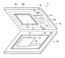
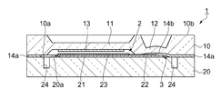
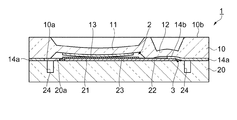
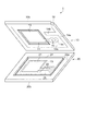
図1は、圧力センサの内部構成を示す分解斜視図である。図2は、圧力センサの外観構成を示す斜視図である。図3は、図2のA−A断面図である。図4は、図2のB−B断面図である。図5は、使用環境下における図2のB−B断面図である。
図6は、圧力センサの製造工程を示すフローチャートである。
次に、図7を参照して、本発明の変形例1について先の実施形態との相違点を中心に説明する。
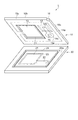
図7は、変形例1に係る圧力センサの内部構成を示す分解斜視図である。
次に、図8を参照して、本発明の変形例2について先の実施形態との相違点を中心に説明する。
図8は、変形例2に係る圧力センサの内部構成を示す分解斜視図である。
この変形例のように、本発明の薄肉部は、受圧基板、対向基板のどちらに設けられていてもよい。
次に、図9を参照して、本発明の変形例3について先の実施形態との相違点を中心に説明する。
図9は、変形例3に係る圧力センサの内部構成を示す分解斜視図である。
例えば、受圧基板には、水晶やガラスの他に、シリコンやセラミック等を用いることもできる。
また、ダイアフラムにおける可動電極は、特許文献1に係る圧力センサのように、シリコン基板に形成されたダイアフラム領域に不純物をドーピングした態様とすることもできる。
また、本発明は、可動電極と誘電体膜とが接触しない(タッチモードではない)タイプの容量型圧力センサについても適用することができる。
また、各実施形態の各構成はこれらを適宜組み合わせたり、省略したり、図示しない他の構成と組み合わせたりすることができる。
Claims (7)
- 中央領域にダイアフラムを有し、前記ダイアフラムの一方の主面に可動電極を有する第1の基板と、
一方の主面の中央の領域に対向電極有する第2の基板と、を備え、
前記可動電極と前記対向電極とが対向するように前記第1の基板と前記第2の基板とを重ねると共に、前記第1の基板及び前記第2の基板の外縁部に沿った領域で前記第1の基板と前記第2の基板面を導電膜を介して接合した圧力センサであって、
前記可動電極または前記対向電極から延出したリード配線を有し、
前記リード配線と対向する基板の対向領域に前記外縁部に沿った領域に設けられた導電膜と導通した第1の導電膜を備え、
前記第1導電膜が形成された領域にバネ性を持たせ、前記リード配線と前記第1の導電膜とを接触させたことを特徴とする圧力センサ。 - 前記第1導電膜が形成された領域は薄肉化された薄肉部を形成することによりバネ性を持たせたことを特徴とする請求項1に記載の圧力センサ。
- 前記第1の導電膜は、前記外縁部に沿った領域に設けられた導電膜を介して前記一基板の外面に形成された端子配線と導通していることを特徴とする請求項1又は2に記載の圧力センサ。
- 前記基板の前記可動電極または前記対向電極から延出した第2の導電膜を有し、該第2の導電膜は前記リード配線と対向しないように形成され、
前記第2の導電膜の少なくとも一部は、一の前記基板に形成されたスルーホールを介して、前記一基板の外面に形成された他の端子配線と導通していることを特徴とする請求項1乃至3のいずれか一項に記載の圧力センサ。 - 二つの前記基板のうち一方の基板の主面における前記可動電極又は前記対向電極と前記外縁部に沿った領域に設けられた導電膜との間に前記可動電極または前記対向電極を囲むスリットを有することを特徴とする請求項1乃至4のいずれか一項に記載の圧力センサ。
- 前記ダイアフラムを有する基板には、水晶板が用いられていることを特徴とする請求項1ないし5のいずれか一項に記載の圧力センサ。
- 前記ダイアフラムを有する基板には、ATカットにより切り出された水晶板が用いられていることを特徴とする請求項6に記載の圧力センサ。
Priority Applications (2)
| Application Number | Priority Date | Filing Date | Title |
|---|---|---|---|
| JP2005242245A JP4258504B2 (ja) | 2005-08-24 | 2005-08-24 | 圧力センサ |
| US11/466,601 US7398694B2 (en) | 2005-08-24 | 2006-08-23 | Pressure sensor and method for manufacturing pressure sensor |
Applications Claiming Priority (1)
| Application Number | Priority Date | Filing Date | Title |
|---|---|---|---|
| JP2005242245A JP4258504B2 (ja) | 2005-08-24 | 2005-08-24 | 圧力センサ |
Publications (2)
| Publication Number | Publication Date |
|---|---|
| JP2007057348A JP2007057348A (ja) | 2007-03-08 |
| JP4258504B2 true JP4258504B2 (ja) | 2009-04-30 |
Family
ID=37882732
Family Applications (1)
| Application Number | Title | Priority Date | Filing Date |
|---|---|---|---|
| JP2005242245A Expired - Fee Related JP4258504B2 (ja) | 2005-08-24 | 2005-08-24 | 圧力センサ |
Country Status (2)
| Country | Link |
|---|---|
| US (1) | US7398694B2 (ja) |
| JP (1) | JP4258504B2 (ja) |
Families Citing this family (3)
| Publication number | Priority date | Publication date | Assignee | Title |
|---|---|---|---|---|
| JP5130151B2 (ja) * | 2008-08-26 | 2013-01-30 | パナソニック株式会社 | 静電容量型半導体物理量センサの製造方法及び静電容量型半導体物理量センサ |
| WO2012073656A1 (ja) * | 2010-12-01 | 2012-06-07 | 株式会社村田製作所 | 圧電発電装置及びその製造方法 |
| CN114459666B (zh) * | 2022-02-14 | 2023-03-17 | 北京航空航天大学 | 一种电容式压差传感器、制造方法及其应用 |
Family Cites Families (6)
| Publication number | Priority date | Publication date | Assignee | Title |
|---|---|---|---|---|
| US4766666A (en) * | 1985-09-30 | 1988-08-30 | Kabushiki Kaisha Toyota Chuo Kenkyusho | Semiconductor pressure sensor and method of manufacturing the same |
| US4771638A (en) * | 1985-09-30 | 1988-09-20 | Kabushiki Kaisha Toyota Chuo Kenkyusho | Semiconductor pressure sensor |
| IL82960A0 (en) * | 1986-06-30 | 1987-12-20 | Rosemount Inc | Differential pressure sensor |
| JPH07174652A (ja) | 1993-12-16 | 1995-07-14 | Omron Corp | 半導体圧力センサ及びその製造方法並びに圧力検出方法 |
| JP2001033328A (ja) | 1999-07-27 | 2001-02-09 | Matsushita Electric Works Ltd | 半導体圧力センサ |
| JP2004214058A (ja) | 2003-01-06 | 2004-07-29 | Smk Corp | 操作パネル入力装置 |
-
2005
- 2005-08-24 JP JP2005242245A patent/JP4258504B2/ja not_active Expired - Fee Related
-
2006
- 2006-08-23 US US11/466,601 patent/US7398694B2/en not_active Expired - Fee Related
Also Published As
| Publication number | Publication date |
|---|---|
| US7398694B2 (en) | 2008-07-15 |
| US20070062294A1 (en) | 2007-03-22 |
| JP2007057348A (ja) | 2007-03-08 |
Similar Documents
| Publication | Publication Date | Title |
|---|---|---|
| JP3114570B2 (ja) | 静電容量型圧力センサ | |
| TWI648527B (zh) | 改良的壓力感測器結構 | |
| JPS6356935B2 (ja) | ||
| KR101213895B1 (ko) | 차량용 엔진의 흡입 공기 압력 측정용의 반도체 비틀림 감지 센서 | |
| CN108871627B (zh) | 一种差分双谐振器型声波压力传感器 | |
| JP6756325B2 (ja) | 圧電振動デバイス | |
| JP2004333133A (ja) | 慣性力センサ | |
| JPWO2010055734A1 (ja) | 半導体圧力センサ | |
| JP4258504B2 (ja) | 圧力センサ | |
| JP2000074768A (ja) | 静電容量型圧力センサ及びその製造方法 | |
| JP2021025966A (ja) | Memsセンサ | |
| JP2007057349A (ja) | 圧力センサ | |
| JP2009288170A (ja) | 半導体圧力センサ | |
| JP2007225344A (ja) | 圧力センサ | |
| JP2009250874A (ja) | 物理量センサおよびその製造方法 | |
| JP2007101222A (ja) | 圧力センサ | |
| JP2007093526A (ja) | 圧力センサ | |
| JP2008032451A (ja) | 容量変化型圧力センサ | |
| JP2007093234A (ja) | 圧力センサ | |
| JPH11241968A (ja) | 静電容量型圧力センサ及びその製造方法 | |
| JP2007057454A (ja) | 圧力センサおよび圧力センサの製造方法 | |
| JPH1022512A (ja) | 静電容量型圧力センサ | |
| JP2713241B2 (ja) | 加速度センサおよびその製造方法 | |
| JP4059306B2 (ja) | サーボ式静電容量型真空センサ | |
| JP2009257916A (ja) | 静電容量型圧力センサ及び静電容量の補償信号の提供方法 |
Legal Events
| Date | Code | Title | Description |
|---|---|---|---|
| RD04 | Notification of resignation of power of attorney |
Free format text: JAPANESE INTERMEDIATE CODE: A7424 Effective date: 20070405 |
|
| A977 | Report on retrieval |
Free format text: JAPANESE INTERMEDIATE CODE: A971007 Effective date: 20080625 |
|
| A131 | Notification of reasons for refusal |
Free format text: JAPANESE INTERMEDIATE CODE: A131 Effective date: 20080701 |
|
| A521 | Written amendment |
Free format text: JAPANESE INTERMEDIATE CODE: A523 Effective date: 20080828 |
|
| A131 | Notification of reasons for refusal |
Free format text: JAPANESE INTERMEDIATE CODE: A131 Effective date: 20081021 |
|
| A521 | Written amendment |
Free format text: JAPANESE INTERMEDIATE CODE: A523 Effective date: 20081114 |
|
| TRDD | Decision of grant or rejection written | ||
| A01 | Written decision to grant a patent or to grant a registration (utility model) |
Free format text: JAPANESE INTERMEDIATE CODE: A01 Effective date: 20090113 |
|
| A01 | Written decision to grant a patent or to grant a registration (utility model) |
Free format text: JAPANESE INTERMEDIATE CODE: A01 |
|
| A61 | First payment of annual fees (during grant procedure) |
Free format text: JAPANESE INTERMEDIATE CODE: A61 Effective date: 20090126 |
|
| FPAY | Renewal fee payment (event date is renewal date of database) |
Free format text: PAYMENT UNTIL: 20120220 Year of fee payment: 3 |
|
| R150 | Certificate of patent or registration of utility model |
Free format text: JAPANESE INTERMEDIATE CODE: R150 |
|
| FPAY | Renewal fee payment (event date is renewal date of database) |
Free format text: PAYMENT UNTIL: 20130220 Year of fee payment: 4 |
|
| FPAY | Renewal fee payment (event date is renewal date of database) |
Free format text: PAYMENT UNTIL: 20130220 Year of fee payment: 4 |
|
| S531 | Written request for registration of change of domicile |
Free format text: JAPANESE INTERMEDIATE CODE: R313531 |
|
| R350 | Written notification of registration of transfer |
Free format text: JAPANESE INTERMEDIATE CODE: R350 |
|
| LAPS | Cancellation because of no payment of annual fees |