JP4187382B2 - Game machine - Google Patents
Game machine Download PDFInfo
- Publication number
- JP4187382B2 JP4187382B2 JP2000090308A JP2000090308A JP4187382B2 JP 4187382 B2 JP4187382 B2 JP 4187382B2 JP 2000090308 A JP2000090308 A JP 2000090308A JP 2000090308 A JP2000090308 A JP 2000090308A JP 4187382 B2 JP4187382 B2 JP 4187382B2
- Authority
- JP
- Japan
- Prior art keywords
- command
- game
- display
- control device
- power
- Prior art date
- Legal status (The legal status is an assumption and is not a legal conclusion. Google has not performed a legal analysis and makes no representation as to the accuracy of the status listed.)
- Expired - Fee Related
Links
Images


Landscapes
- Pinball Game Machines (AREA)
Description
【0001】
【発明の属する技術分野】
本発明は、電源遮断時にも遊技制御に関連する情報を記憶保持し、下位の従属制御装置(例えば、表示制御装置)への制御信号の送信処理を電源再投入時(少なくとも停電復帰時含む)に電源遮断時点の状態から再開する主制御装置(例えば、遊技制御装置)を備えるパチンコ機等の遊技機に係わり、電源再投入時に、従属制御装置を介した特定機器の制御動作が、簡素な構成で円滑に再開される遊技機に関する。
【0002】
【従来の技術】
従来、パチンコ遊技機、アレンジボール遊技機、雀球遊技機などの遊技機としては、電力の供給を受けて動作し、プログラムの実行に従って遊技制御動作を行うCPU等からなる遊技制御装置(主制御装置)が設けられ、予め定められた遊技進行順序に従って遊技状態を進行制御するように構成されたものがある。このような遊技機では、通常、機内に複数設けられた被制御機器の動作を前記遊技制御装置が統括的に管理制御して遊技を進行させる構成になっているとともに、この遊技制御装置から遊技状態等に応じて適宜送信される制御信号に基づいて、前記被制御機器のうちの特定機器の動作を個別に制御する従属制御装置(遊技制御装置の下位の制御装置)が設けられている。
例えば、この種の遊技機の中には、液晶ディスプレイ又はCRTディスプレイなどの表示装置が遊技盤面中央等に設けられ、この表示装置(特定機器)が遊技制御装置からの表示制御信号に基づく表示制御装置(従属制御装置)の制御によって駆動されて、遊技の一部をなす表示ゲーム(例えば、識別情報の変動表示ゲーム)や、遊技状態を演出する演出表示などが実行されるタイプがある。また通常、この種の遊技機には、演出用の装飾ランプなどの電飾部材が各所に設けられ、この電飾部材(特定機器)も、遊技制御装置からの装飾制御信号に基づく装飾制御装置(従属制御装置)の制御処理によって駆動制御される。
【0003】
【発明が解決しようとする課題】
ところで、上述したような遊技機にあっては、遊技中に停電等が発生して遊技機への電力供給が絶たれた場合、従来では、遊技機がどのような遊技状態であったかの遊技状態に関する情報などが消滅してしまう。このため、電力供給が再開されても(即ち、電源が再投入されても)、電源遮断時に実行されていた遊技状態から遊技を再開することができず、停電発生等に伴う遊技者への補償ができないなど不都合が生じる。つまり、電源遮断前には、いわゆる大当たりなどの遊技者に有利な状態にあったのに、それが停電等で中断して、電源再投入後に大当たりでない状態から遊技が再開するような事態が発生する恐れがあり、この場合遊技者は取り返しのつかない不利益を被ることになる。
そこで出願人は、電力供給が絶たれたときに遊技機の遊技状態等に関する情報を記憶保持するための記憶保持手段(例えば、電源遮断時にもバックアップ電源が供給されるメモリよりなるもの)を遊技制御装置(主制御装置)に対して設けて、電源再投入されるまでの間、遊技状態等に関する情報をこの記憶保持手段に記憶保持し、電源再投入時には、表示制御装置などの従属制御装置への制御信号の送信処理も含めて、停電等による電源遮断時点の遊技状態から遊技制御装置が制御処理を再開する遊技機を提案している。
【0004】
しかし、このように遊技状態等を記憶保持する遊技機にあっては、電源再投入時に電源遮断時の遊技状態から遊技を再開するにあたり、下位の従属制御装置を介した特定機器(例えば、表示装置)の制御動作に関して、以下のような問題点があった。
(イ)即ち、停電発生等により送信が中断した制御信号(例えば、表示制御信号)を、電源再投入時にどのように処理するかが、問題であった。一つの方式としては、遊技制御装置においてもう一度その制御信号を作り直して(即ち、再生して)、その制御信号全体を再送信する構成が考えられる。しかし、このような指令の再生成や再送信があり得る構成とすることは、遊技制御装置の不正な改造等が発見困難になるなど不正対策上不利になる欠点があり採用できない。
(ロ)また、電源再投入時に記憶保持していた遊技状態等から従属制御装置に対する制御信号を再生成することは、通常の制御処理とは別個の特殊な処理となるため、プログラムが複雑化して、プログラムの作成やシステム設計自体が困難になるとともに、プログラムを格納するROM等の容量が増大し、CPU等にかかる負担も増大する問題がある。
【0005】
(ハ)また、電源遮断時に送信が中断した制御信号は全く送信せず、新たに発生した遊技状態に対応する制御信号(例えば、次の画面を表示するための次の表示制御信号)から従属制御装置への送信を再開する構成も考えられるが、単純にこのような構成を採用した場合には、電源再投入時に従属制御装置が制御する被制御機器の動作に空白期間(動作が無意味に停止した期間)が生じて、遊技者が違和感や不信感を抱く恐れがあるという問題がある。例えば、表示制御装置に対する一連の表示制御信号の送信が停電等によって中断した場合、電源再投入時にその一連の表示制御信号は全く送信せず、新たに発生した遊技状態に対応する次の画面を表示するための次の正常な表示制御信号から単純に送信処理を再開するようにした場合には、次の遊技状態に移行するまでの間、表示装置の表示動作に空白期間が生じて、これを見ている遊技者が違和感や不信感を抱く恐れがある。
そこで本発明は、変動表示ゲームが行われている場合であって、電源が遮断されたときにおける遊技制御情報を記憶保持し、電源が再投入された場合に、停電復帰画面を表示して空白期間の発生を確実に回避して、遊技者の違和感や不信感の問題を信頼性高く解消するとともに、簡素な構成で円滑に遊技が再開される遊技機を提供することを目的とする。
【0006】
【課題を解決するための手段】
上記目的達成のため、請求項1記載の発明は、遊技の進行を制御する遊技制御装置と、
前記遊技制御装置から送信される表示制御信号に基づき、表示装置に複数の図柄を変動表示させて停止させる変動表示ゲームを行わせる表示制御装置と、
を備え、
前記変動表示ゲームの停止態様が特定表示態様となったときに特典を付与するようにした遊技機において、
前記遊技制御装置から表示制御装置に送信される表示制御信号は、
前記変動表示ゲームの変動時間および変動表示の開始を指示する主指令コマンドと、
前記変動表示ゲームの停止態様を指示する補助指令コマンドと、
を含み、
前記主指令コマンドは、該主指令コマンドを送信するためのコントロール信号に、前記表示制御装置において割込を発生させて受信処理を開始させるための割込信号を含ませ、
前記補助指令コマンドは、該補助指令コマンドを送信するためのコントロール信号に、前記割込信号を含ませないようにし、
前記遊技制御装置は、電源遮断時においても電源遮断時点の遊技の制御に関する遊技制御情報を記憶保持可能な記憶保持手段を備え、
前記変動表示ゲーム中に電源が遮断した場合において該電源遮断時に未送信の表示制御信号がある場合は、電源再投入時に停電復帰信号を送信した後に、その未送信の表示制御信号の送信を実行し、
前記主指令コマンドを送信後、前記変動表示ゲーム中に前記補助指令コマンドが未送信の状態で電源が遮断した場合であって、電源再投入時に停電復帰信号を前記表示制御装置に送信後、前記補助指令コマンドを前記表示制御装置に送信し、
前記表示制御装置は、前記遊技制御装置から停電復帰信号を受信した場合に、停電復帰報知画面を表示し、その後送信される前記補助指令コマンドを受信しないことを特徴とする。
請求項2記載の発明は、遊技の進行を制御する遊技制御装置と、
前記遊技制御装置から送信される表示制御信号に基づき、表示装置に複数の図柄を変動表示させて停止させる変動表示ゲームを行わせる表示制御装置と、
を備え、
前記変動表示ゲームの停止態様が特定表示態様となったときに特典を付与するようにした遊技機において、
前記遊技制御装置から表示制御装置に送信される表示制御信号は、
前記変動表示ゲームの変動時間および変動表示の開始を指示する主指令コマンドと、
前記変動表示ゲームの停止態様を指示する補助指令コマンドと、
を含み、
前記主指令コマンドは、該主指令コマンドを送信するためのコントロール信号に、前記表示制御装置において割込を発生させて受信処理を開始させるための割込信号を含ませ、
前記補助指令コマンドは、該補助指令コマンドを送信するためのコントロール信号に、前記割込信号を含ませないようにし、
前記遊技制御装置は、電源遮断時においても電源遮断時点の遊技の制御に関する遊技制御情報を記憶保持可能な記憶保持手段を備え、
前記変動表示ゲーム中に電源が遮断した場合において該電源遮断時に未送信の表示制御信号がある場合は、電源再投入時に停電復帰信号を送信した後に、その未送信の表示制御信号の送信を実行し、
前記主指令コマンドを送信後、前記変動表示ゲーム中に前記補助指令コマンドが未送信の状態で電源が遮断した場合であって、電源再投入時に停電復帰信号を前記表示制御装置に送信後、前記補助指令コマンドを前記表示制御装置に送信し、
前記表示制御装置は、前記遊技制御装置から停電復帰信号を受信した場合に、停電復帰報知画面を表示し、その後送信される前記補助指令コマンドを受信し、該受信した補助指令コマンドを破棄することを特徴とする。
【0007】
また、上記「遊技制御情報」として記憶保持すべき情報は、前記制御信号の送信処理を電源遮断時点の状態から再開するために必要な情報であり、これ以外のものを含んでいてもよい。
【0008】
また、「電源遮断時」には、少なくとも停電等の不用意な電源遮断時が含まれ、通常の電源オフ操作による電源遮断時が含まれてもよいし、含まれなくてもよい。
【0009】
また同様に、「電源再投入時」には、少なくとも停電等の不用意な電源遮断からの電源復帰時(停電復帰時)が含まれ、通常の電源操作による電源遮断からの電源復帰時が含まれてもよいし、含まれなくてもよい。
【0010】
【発明の実施の形態】
以下、本発明の実施の形態をパチンコ遊技機に適用した例について説明する。
A.遊技機の正面構成
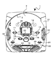
図1はパチンコ遊技を行う遊技機の遊技盤を示す正面図である。図1において、1は遊技盤であり、前面の略円形領域がガイドレール2で囲まれることにより遊技領域3が形成されている。
遊技盤1には、アウト球流入口(変動入賞装置14の取付部材の後部にあり、図示略)、本発明の表示装置(被制御機器)としての特別図柄表示装置12、普通電動役物タイプの始動入賞口13、変動入賞装置14(大入賞口)、普図始動ゲート15、16、複数の一般入賞口17〜22、特図始動記憶表示器23、普通図柄表示装置24、普図始動記憶表示器25、風車と呼ばれる打球方向変換部材26(一部のみ符号付けで他は煩雑になるで略)、多数の障害釘(図示を省略)が設けられている。
特別図柄表示装置12は、画像、図柄などの識別情報(以下、場合により特図という)を表示可能な画面Gを備え(図4参照)、その画面Gには複数の変動表示領域を形成可能で、形成した変動表示領域のそれぞれに複数の特図を表示可能である。例えば、図4(b)では、画面Gの略中央部に三つの変動表示領域が横3列に形成され、各変動表示領域には、数字や文字等よりなる特図を停止状態で表示(停止表示)したり、あるいは変動状態(例えば、縦方向にスクロールする状態)で表示(変動表示)したりすることが可能である(なお、図4(b)は、それぞれ「1」、「2」、「3」の文字が各変動表示領域に停止表示された状態を例示している)。
【0011】
遊技盤1に設けられた複数の全ての入賞口、すなわち始動入賞口13(内部に特図始動センサ131が配置)、変動入賞装置14(大入賞口:内部に後述のカウントセンサ134および継続センサ133が配置)、および一般入賞口17〜22(内部に後述の入賞センサA1〜ANが配置)については、各入賞口毎に入賞センサ(例えば、近接センサ:ただし図1では省略)が配置されており、これらの入賞口に入賞すると、入賞価値(各入賞口によって予め決定された遊技価値:例えば、5個賞球、15個賞球等の賞球数)に対応する賞球データ(賞球数情報)が遊技制御装置105(主基板;図2参照)によって設定され、排出制御装置104(払出制御基板;図2参照)に送信されるようになっている。
また、遊技盤1の周囲には遊技盤装飾部材31が配置されるとともに、サイドランプ32、33が配置されている。サイドランプ32、33は、例えばリーチや大当りの際に点滅あるいは点灯して遊技を装飾する電飾部材である。
なお、遊技盤1における遊技領域2は、パチンコ球を用いて遊技を行うものであれば、例えば、いわゆる「第1種」に属するもの、あるいは、変動表示装置を備えた「第3種」に属するもの、あるいは他の機種等であってもよく、任意の構成をとり得るが、一例として本実施の形態では「第1種」に属するタイプのものを用いている。
また、本実施の形態では、遊技者がプリペイドカードを挿入することで球貸しが可能となるカードユニット202(図2に示す)が、遊技機本体の側部に一体的に配設されるカードリーディング機(いわゆるCR機)と称される種類のパチンコ機を例示しているが、これに限定されないこともいうまでもない。
【0012】
B.電源供給系統
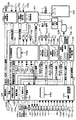
次に、本遊技機の電源供給系統について、図面を参照して説明する。
図2は本遊技機における電源供給系統及び制御系統を示す図である。図2において、本遊技機には、外部からAC24Vが供給されるようになっており、外部電源であるAC24Vは電源基板102に分配される。
電源基板102は、電源ユニットを構成する基板であり、AC24Vを直流に変換して各種のDC電圧を生成して各制御装置に供給する電源回路102aと、この場合遊技制御装置を構成する主基板105と排出制御装置を構成する払出制御基板104のRAMにバックアップ電源(DC5VBB)を供給するバックアップ回路102bと、電源遮断時(停電時含む)に停電検出信号とリセット信号を出力する停電検出回路102cと、過電流防止用のヒューズ102dと、電源投入操作用の電源スイッチ102eとを備える。
ここで、電源回路102aは、具体的には、ソレノイド駆動用などのDC32V、カードユニット用のDC24V、ランプ類駆動用、センサ駆動用およびバックライト駆動用などのDC12Vを駆動用電源として生成するとともに、各制御装置を動作させるための制御装置用電源としてDC5Vを生成する。そして、DC32VおよびDC5Vを発射制御基板103(発射制御装置)に、DC32V、DC12V、DC5Vを払出制御基板104(排出制御装置)に、DC32V、DC12V、DC5Vを主基板105(遊技制御装置)に、DC12V、DC5Vを音声制御基板106(音制御装置)に、DC12VおよびDC5Vをランプ制御基板107(装飾制御装置)に、DC12VおよびDC5Vを表示制御基板108(表示制御装置)に、DC24Vをカードユニット接続基板201を介してカードユニット202や操作パネル基板203に供給する。なお、各制御基板やカードユニット202等の構成や機能については、後述する。
また、バックアップ回路102bは、バックアップすべき電源端子(この場合、主基板105のマイコンチップ105a内のRAMと、払出制御基板104のマイコンチップ104a内のRAMの電源端子)に接続されたバックアップ電源としてのコンデンサ(図示省略)と、このコンデンサに電源回路102aで生成されたDC5Vを不可逆的に供給するダイオード(図示省略)とよりなり、電源遮断時に所定のバックアップ補償期間以上DC5V相当の電源供給を行うもので、この場合このバックアップ電源(DC5VBB)は、遊技制御装置(主制御装置)を構成する主基板105のRAMと、排出制御装置(従属制御装置)を構成する払出制御基板104のRAMに供給されている。
【0013】
なお、従前の一般的なパチンコ機は、全ての入賞球を一カ所に集めて1個ずつ検出し、入賞球を賞球払出が完了するまで保持しておくセーフユニットを備えていて、停電等があってもこのセーフユニットに保持されている入賞球を確認することで、未排出の賞球数がある程度判定できた。しかし、本形態例の場合には、このようなセーフユニットを備えずに、前述した如く各入賞口毎に入賞検出を行う構成であるため、未排出の賞球の情報をソフト的に保持しておく必要があり、そのためにこのようなバックアップ電源が供給される構成となっている。また、停電等により中断した遊技を、電源再投入後に継続的に再開するためには、前述したように、電源遮断時の遊技状態等を再現するための情報を記憶保持する必要があり、そのためにもこのようなバックアップ電源が少なくとも遊技制御装置の
RAMに(この場合排出制御装置のRAMにも)供給される構成となっている。
【0014】
また、電源基板102内の停電検出回路102cは、電源回路102aにおけるDC5V生成回路(図示省略)への電源供給が断たれること(即ち、停電等の電源遮断)を事前に検出(例えば、DC32Vが停電検出電圧である22Vまで低下したとき停電開始として検出)して、遊技制御装置(主基板105)と排出制御装置(払出制御基板104)の各CPUに対し、停電検出信号を出力する回路である。
この停電検出回路102c内には、リセット出力部が設けられ、このリセット出力部からは、各制御装置(主基板105,払出制御基板104,発射制御基板103,音声制御基板106,ランプ制御基板107,表示制御基板108)のCPU等(発射制御基板103の場合には、ロジック回路)をリセットすべき時期(例えば、DC32Vが停電検出電圧まで低下した時点から所定時間経過後)に、これら各制御装置のCPU等に対してリセット信号が出力されるようになっている。
なお、リセット信号とは、一般にCPU等を初期状態に戻すための信号であるが、CPU等では、このリセット信号が入力されると、このリセット信号が入力中は実質的に動作を停止する。そして、このリセット信号が解除されると各CPU等は再起動する。
【0015】
また、停電検出信号を受信した主基板105や払出制御基板104(遊技制御装置や排出制御装置)のCPUは、例えば強制割込(NMI割込)によって停電処理を実行する。
この停電処理は、全出力をオフするとともに、停電フラグをセットしたりRAMへのアクセスを禁止するなどの処理を実行した後、最終的にリセット待ちで待機するものである。
このような構成であれば、停電等の際に各CPUが正常に動作できる電圧時(完全に電源ダウンする前に)に各CPUの機能を停止させて、停電等により各CPUが不安定になって主基板105や払出制御基板104の各RAMに不定な値が書き込まれることなどが信頼性高く防止でき、各RAMに記憶されている内容(例えば未排出の賞球データや後述の遊技状態を再開するための情報等)を確実に保持できるなどの利点が得られる。
またこの場合、主基板105(遊技制御装置)のCPUと、払出制御基板104(排出制御装置)のCPUは、上記停電処理において、全レジスタやスタックポインタ等のデータ(停電等による中断アドレスのデータ含む)を前述したようにバックアップされたRAMの所定エリアにセーブ(登録)する処理を、RAMへのアクセスを禁止する処理の前に実行する。これにより、主基板105と払出制御基板104において、電源遮断時点(この場合正確には、前記停電検出信号が出力された停電検出時点)の遊技状態或いは制御状態の情報など(遊技制御情報)を電源遮断中も記憶保持することができ、電源再投入後には、主基板105と払出制御基板104による制御処理を、前記停電検出信号が出力された停電発生時点の状態からそのまま継続的に再開することが可能となる。
【0016】
C.制御系統
次に、遊技機301の制御系統(各制御基板等の構成や機能)について、図2を参照して説明する。
図2において、主基板105は、遊技の総括的制御(遊技進行の制御やそのための各被制御機器の直接的又は間接的な制御含む)を行う遊技制御装置(主制御装置)を構成するもので、パチンコ遊技等に必要な役物制御を行うワンチップマイコンからなる遊技用演算処理装置105a(遊技用マイクロコンピュータ:いわゆるアミューズチップ用のICとして製造)を含んで構成され、この遊技用演算処理装置105aは、CPU、ROM、RAM、及び各種信号の入出力を行う入出力インターフェース(図示省略)を備えている。遊技用演算処理装置105aのRAMには、賞球データ(例えば、7個賞球、15個賞球というデータ)を格納するエリアや、電源遮断時の遊技状態を再開するための情報など(前述した全レジスタやスタックポインタ等のデータ)を格納するエリアがあり、またこのRAMは前述のように電源遮断時(停電時含む)でも電源供給がバックアップ可能で、所定のバックアップ保証期間の間はその全データが記憶保持可能となっていて、本発明の記憶保持手段に相当する。
またこの場合、主基板105には、試射試験信号端子105b(この場合正確には、端子群)が設けられ、ここから試験時に必要な各種信号が容易に取り出せるようになっている。
【0017】
遊技用演算処理装置105aの入力インターフェースには、特図始動センサ131、普図始動ゲートセンサ132a,132b、継続センサ133、カウントセンサ134、入賞センサA1〜ANからの検出信号が入力される。なお、入賞センサA1〜ANは一般入賞口に入賞した入賞球をそれぞれ検出するセンサであり、遊技盤に一般入賞口がn個ある場合には、入賞センサはn個配置される。
特図始動センサ131は特図の始動入賞口13に入賞した入賞球を検出するセンサであり、普図始動ゲートセンサ132a,132bは、普図始動ゲート15、16に入賞(通過)した入賞球をそれぞれ検出するセンサであり、継続センサ133は変動入賞装置14の大入賞口内における継続入賞流路(いわゆる特別入賞口を通過する流路)に流入した入賞球を検出するセンサであり、カウントセンサ134は、変動入賞装置14の大入賞口内における一般入賞流路(特別入賞口を通過しない流路)に流入した入賞球を検出するセンサである。
また、遊技用演算処理装置105aの入出力インターフェースには、賞球排出および貸球排出のための遊技球が有るかどうかを検出する半端球検出スイッチ141、遊技機前面下部に設けられた下皿(図示省略)の満杯状態(球の過剰貯留)を検出するオーバーフロースイッチ142、遊技機前面のガラスを支持するガラス枠(金枠)が開けられたことを検出するガラス枠開放スイッチ143からの検出信号も入力されている。また、後述する排出ユニットの賞球検出センサ161、162からの検出信号も入力されている。
【0018】
一方、遊技用演算処理装置105aの入出力インターフェースからは、前述の特別図柄表示装置12を構成するLCD等の表示装置本体12aを制御する表示制御基板108、遊技盤1上のランプ32,33や特図始動記憶表示器23及び普図始動記憶表示器25などの制御を行うランプ制御基板107、スピーカ106bを駆動して効果音などの出力制御を行う音制御装置106、前述の普通図柄表示装置24、変動入賞装置14内に設けられた誘導部材(遊技球を継続入賞流路又は一般入賞流路の何れかに選択的に誘導する部材;図示省略)の誘導方向を切り替えるための方向切り替えレバーソレノイド135、前述の始動入賞口13(普通変動入賞装置)を駆動する普通電動役物ソレノイド(普電ソレノイド)136、変動入賞装置14の開閉扉を駆動する大入賞口ソレノイド137、盤用外部接続端子盤138、試射試験信号端子105bに信号が出力される。
また、この入出力インターフェースからは、払出制御基板104(排出制御装置)に対して、賞球データ等の信号が賞球パラレル通信によって出力される。即ち、主基板105が構成する遊技制御装置は、遊技盤1の各入賞口毎に設けられた入賞センサ131,133,134,A1〜ANにより遊技球の入賞が検出されると、入賞口の入賞価値に対応して予め設定された賞球数の情報(賞球データ)を、排出制御装置104へパラレル通信(賞球パラレル通信)によって送信する機能を有する。
なお、この遊技制御装置(主基板105)の遊技用演算処理装置105aは、電源遮断時に中断した表示制御基板108(従属制御装置)への表示制御信号の送信処理(表示パラレル通信による表示制御信号の送信処理)を、電源再投入時に電源遮断時の状態からそのまま再開する機能(本発明の送信処理再開手段としての機能)と、この送信処理の再開に先立って、停電復帰信号を表示制御基板108に送信する機能(本発明の停電復帰信号送信手段としての機能)を有している(詳細後述する)。
【0019】
次に、発射制御基板103は、発射制御装置を構成するもので、この場合ロジック回路よりなり、発射操作ハンドル(図示省略)の回動量に応じて発射装置(図示省略)の発射モータ103aを駆動制御し、発射操作ハンドルの回動量に対応した強さで遊技球を発射させる制御を行う。なお、発射制御装置103には、発射操作ハンドルに設けられたタッチセンサ103bや発射停止スイッチ103cの信号が入力されており、発射操作ハンドルから遊技者の手が離れたことがタッチセンサ103bにより検出されるか、或いは、発射停止スイッチ103cから操作信号が入力されると、発射ユニットの発射動作が強制停止される構成となっている。また、発射制御装置103には、排出制御装置104から発射停止信号が入力されるようになっており、この発射停止信号は、排出制御装置(払出制御基板104)側で何らかの異常を検知した場合に、発射ユニットの発射動作を強制停止したり、あるいは異常が解消された場合に発射動作を可能にするための信号である。
【0020】
次に、払出制御基板104は、排出制御装置を構成するもので、遊技制御装置(主基板105)から賞球パラレル通信によって送信された賞球データ等や、賞球検出センサ161、162からの検出信号に基づいて賞球排出の制御を実行し、また、後述するように貸球の排出制御も行う。
この場合の払出制御基板104は、ワンチップマイコンからなる払出用演算処理装置104aを含んで構成され、この払出用演算処理装置104aは、CPU、ROM、RAM、及び入出力用インターフェースとを含む。ここで、払出用演算処理装置104aのCPUは、遊技球の排出(賞球排出および貸球排出を含む)に必要な処理を行い、そのROMは排出制御に必要なプログラム等を格納している。また、払出用演算処理装置104aのRAMは賞球データ(例えば、7個賞球、15個賞球というデータ)を格納する賞球データメモリエリアを有している。また、このRAMは前述のように電源遮断時(停電時含む)でも電源供給がバックアップ可能で、所定のバックアップ保証期間の間はその全データが記憶保持可能となっている。
また、払出用演算処理装置104aは、その入出力用インターフェースを介してカードユニット接続基板201との間でカードユニット通信を行うことによって、カードユニット接続基板201を介してカードユニット202や操作パネル基板203との間で信号(カードユニット制御信号や操作パネル信号)の授受を行い、貸球排出に必要な制御を行う。なお、操作パネル基板203は、遊技機前面下方の前面操作パネル(図示省略)に設けられた貸球排出のための操作部材や表示部材(図示省略)用の接続回路等が設けられた基板で、例えば前記前面操作パネルの裏側に配設されている。
また、払出用演算処理装置104aの入出力用インターフェースには、後述する排出ユニットの貸球検出センサ175、176や賞球検出センサ161、162からの信号が入力されている。
また、払出用演算処理装置104aの入出力用インターフェースからは、後述する排出ユニットの球排出モーター181、ストッパーソレノイド182、および流路切換ソレノイド183に制御信号が出力されるとともに、枠用外部接続端子盤139に枠用外部情報が出力されている。
【0021】
なおここで、排出ユニット(図示省略)や、排出制御装置(払出制御基板104)による排出制御について説明しておく。
排出ユニットは、払出制御基板104によって制御されて、遊技機裏側上部に配置された貯留タンク(図示省略)から誘導された遊技球の排出(賞球としての賞球排出又は貸球としての貸球排出)を実行する球排出機構であり、この場合、貯留タンクから誘導された遊技球が流下する遊技球流路が2列ある2条タイプである。ユニット上部には、各遊技球流路の開口部に外周の一部が入り込むように配置された2枚のスプロケット(図示省略)が設けられ、これらスプロケットの外周の谷部に遊技球が1個宛はまり込んで、必ずこのスプロケットの回転を伴いながら遊技球が流下して排出されるようになっている。そして、これらスプロケットを一括して回転駆動する1個のパルスモータからなる球排出モーター181(図2に示す)と、重力によるスプロケットの不用意な回転(即ち、球の不用意な排出)を防止すべくスプロケット(又はスプロケットと一体に回転する部材)に係止する方向に付勢されたストッパー(図示省略)と、このストッパーの係止を解除するストッパーソレノイド182(図2に示す)とを有している。
【0022】
また、この排出ユニットは、各遊技球流路がユニット下部でそれぞれ二つに分岐して、一方が賞球を通過させる賞球流路(図示略)となっており、他方が貸球を通過させる貸球流路(図示略)となっている。この分岐部には、流路切換弁(図示略)が設けられ、この流路切換弁が流路切換ソレノイド183(図2に示す)に駆動されて揺動することにより、遊技球流路の下流側に排出された遊技球が、賞球流路と貸球流路のうちのいずれか一方を通過する構成となっている。
この排出ユニットでは、排出制御装置の制御によりストッパーソレノイド182が作動すると(励磁されると)、前記ストッパーの係止状態が解除され、この係止解除状態において、排出制御装置の制御により球排出モータ181が作動して前記スプロケットが排出方向に所定量だけ回転することによって、それに対応した数量の遊技球が下流側に重力により送り出される。そして、こうして送り出された遊技球は、排出制御装置の制御に基づく前記流路切換ソレノイド183の動作によって、賞球流路又は貸球流路の一方から排出され、所定量の賞球排出又は貸球排出が実現される。
また、こうして所定量の遊技球が排出された直後には、排出制御装置の制御によりストッパーソレノイド182が即座に非作動状態(非励磁状態)に戻され、前記スプロケットの回転が的確に停止される。
また、貸球検出センサ175,176は、前述した各貸球流路を通過する遊技球(即ち、貸球)をそれぞれ検出するセンサであり、賞球検出センサ161,162は、前述の各賞球流路を通過する遊技球(即ち、賞球)をそれぞれ検出するセンサである。
【0023】
次に、音声制御基板106は、音制御装置を構成するもので、CPU106aを含むマイクロコンピュータよりなり、遊技制御装置(主基板105)から音声パラレル通信によって送信された音データを含む制御信号に基づき、効果音を生成してスピーカ106bから出力する等、効果音に関する制御を行う。
また、ランプ制御基板107は、装飾制御装置を構成するもので、CPU107aを含むマイクロコンピュータによりなり、遊技制御装置(主基板105)からランプパラレル通信によって送信された装飾データを含む制御信号に基づき、遊技盤1に配置されたサイドランプ32、33や特図始動記憶表示器23及び普図始動記憶表示器25等の電飾部材や表示部の発光を制御するとともに、この電飾部材や表示部に電源を供給している。
【0024】
また、表示制御基板108は、表示制御装置を構成するもので、やはりCPU108aを含むマイクロコンピュータによりなり、遊技制御装置(主基板105)から送信される前述の表示制御信号に基づき特別図柄表示装置12の画像表示を制御するとともに、特別図柄表示装置12に電源を供給している。具体的には、例えば、表示制御装置は特別図柄表示装置12の変動表示領域に複数の特図(識別情報)を変動表示させて停止させる変動表示ゲームを行い、変動表示ゲームの停止態様が特定の組み合せ態様となったときに特典を付与(例えば、大当り発生)可能とする制御を行う。
なお、表示制御装置(表示制御基板108)は、図9のように、CPU108a、ROM152、RAM153、DMAC(ダイレクトメモリアクセスコントローラ)154、インターフェース155、VDC(ビデオディスプレーコントローラ)156、画像や文字等の表示データを格納したフォントROM157、γ補正回路158、発振器(クロック)159、バッファ回路160などから構成され、前記表示制御信号に基づいて表示装置12を制御して、前記特図の表示を実現するとともに、演出用の所定のキャラクタなどの画像(動画又は静止画)の表示も実行する。
ここで、バッファ回路160は、遊技制御装置(主基板105)から表示制御装置(表示制御基板108)へ向かう方向にのみ信号(表示制御信号の信号)を通過させる回路であり、本発明の伝達方向規制手段に相当している。これにより、表示制御装置側から遊技制御装置側に信号が伝わることが防止され、表示制御装置に不正改造が加えられても、この不正改造によって出力される信号が遊技制御の中枢である遊技制御装置側に伝わることはない。
また、この表示制御基板108には、図2に示すように、試射試験信号端子108b(この場合正確には、端子群)が設けられ、ここから試験時に必要な各種信号が容易に取り出せるようになっている。
【0025】
なおこの場合、遊技制御装置(主基板105)は、本発明の主制御装置に相当し、その他の制御装置(払出制御基板104,発射制御基板103,音声制御基板106,ランプ制御基板107,表示制御基板108)は、本発明の従属制御装置に相当している。
但し、本形態例の場合には、表示制御装置(表示制御基板108)に関して本発明を適用している。
そして、表示制御装置(表示制御基板108)のCPU108aは、電源再投入時に、遊技制御装置から送信される停電復帰信号に応じて、停電復帰メッセージ画面(停電復帰報知画面)を表示して、円滑に特別図柄表示装置12の表示を再開する機能を有する(詳細後述する)。
【0026】
次に、盤用外部接続端子盤138は、主基板105に接続された遊技盤側の外部情報端子が設けられた基板であり、ここから外部の管理装置(図示省略)に、盤用外部情報(例えば、大当り信号等)を出力するためのものである。
また、枠用外部接続端子盤139は、払出制御基板104やタンク球切れスイッチ139aに接続された枠側の外部情報端子が設けられた基板であり、ここから外部の管理装置に、枠用外部情報(例えば、賞球や貸球の検出信号や、タンク球切れ信号)が出力されている。なお、タンク球切れスイッチ139aは、前述した貯留タンクの遊技球の量が不足している(又はゼロである)ことを検出して、遊技球の補給を島設備側に要求するタンク球切れ信号を出力するセンサである。
また、管理装置は、ホール全体の遊技機、島設備等を管理するもので、上記盤用外部接続端子盤138や枠用外部接続端子盤139を介して入力された各種信号に基づいて営業上の必要なデータを演算処理し、処理したデータを必要に応じてディスプレイに表示したり、印刷したりするものである。
【0027】
D.遊技の概要
次に、本実施の形態の遊技機で行われる遊技の概要について説明する。
ガイドレール2を介して遊技領域中に打込まれた遊技球が、特図の始動口(チャッカー)を兼ねた普通電動役物タイプの始動入賞口13に入賞すると(即ち、始動入賞があると)、特別図柄表示装置12の表示画面の複数の変動表示領域において多数の特図(数字、文字、記号、模様等よりなるもの)が変動(例えば、スクロール)する表示(いわゆる変動表示)が行われて、変動表示ゲームが行われる。
そして、この変動表示ゲーム結果(停止した特図の組合せ)が特定表示態様(例えば、「7、7、7」などのゾロ目)であれば、大当りと呼ばれる遊技価値が付与される。なお制御上は、例えば始動入賞があったことを条件として、大当り乱数(遊技価値判定用乱数)などの各種乱数の値が抽出記憶されて、この抽出記憶された乱数値と予め設定された判定値とが判定時に比較判定され、この比較判定結果に基づいて、予め停止図柄(大当りとするか否か)やリーチアクションを行うか否かなどが決定され、この決定に応じて上記変動表示が開始される。
また、いわゆる時短(時間短縮)の制御が行われている場合には、特図および/又は普図の変動の開始から終了までの時間が通常よりも短縮され、その分だけ時間当たりの変動表示ゲームの頻度が実質的に増加して有利となる。また、いわゆる確率変動の制御によって大当りの確率が高確率に設定されていると、通常よりも大当りとなる確率が増加する。
【0028】
この大当りになると、変動入賞装置14の大入賞口の開閉扉が、規定時間(例えば、30秒)を越えない範囲内において、例えば10個入賞までの期間だけ一時的に開放される開放動作が行われる。そして、この開放動作は、継続入賞球の検出(継続センサ133による入賞球の検出)が行われることを条件に、例えば、16ラウンドまで複数回行われる。
また、上記特図の変動表示ゲーム中又は大当り中に、始動入賞口13にさらに遊技球が入賞したときには、特図始動記憶表示器23が点灯してこの場合4個まで記憶され、変動表示ゲーム又は大当りが終了した後に、その記憶(即ち、始動記憶)に基づいて上記特図の変動表示ゲームが繰り返される。
一方、遊技中に、遊技球が普図始動ゲート15、16に入賞(通過)したときは、普通図柄表示装置24の普図(この場合、一桁の数字)の変動表示による普図の変動表示ゲームが行われる。そして、この変動表示ゲーム結果(停止した普図)が所定の態様(例えば、「7」)であれば、普図当りと呼ばれる遊技価値が付与される。
この普図当りになると、始動入賞口13の一対の開閉部材が逆ハの字に開いた開放状態に、例えば0.5秒程度保持される遊技が行われる。これにより、始動入賞口13に遊技球が入賞し易くなり、その分、特図の変動表示ゲームの実施回数が増えて大当りになる可能性が増す。
また、上記普図の変動表示ゲーム中に、普図始動ゲート15、16にさらに遊技球が入賞したときには、普図始動記憶表示器25が点灯してこの場合4個まで記憶され、普図の変動表示ゲームの終了後に、その記憶に基づいて上記普図の変動表示ゲームが繰り返される。
【0029】
E.制御系の動作
次に、前述した制御系により行われる本遊技機の特徴的な制御内容(主に電源再投入時停電復帰時の表示制御)について、説明する。
(a)表示制御信号の内容
遊技制御装置(主基板105)から表示制御装置(表示制御基板108)に表示パラレル通信によって送られる表示制御信号は、例えば8ビットのコマンドデータを送信するための8ビットのパラレル信号(D0〜D7)と、これらコマンドデータの通信用の2ビットのコントロール信号(START信号,STB(ストローブ)信号)とよりなる。そして、図6〜8に例示したように、コマンドデータには、MODE、及びACTIONの2種類があり、これらのコマンドデータがSTART信号に続いてSTB信号と同期して順次送信され、表示制御基板108のCPU108aがSTB信号を確認しつつこれら2種類のコマンドデータを順次読みとる構成となっている。即ち、START信号は、MODE、及びACTIONよりなる一組のコマンドデータに先立って、一度だけアクティブになり、STB信号は、MODE、及びACTIONの各コマンドデータそれぞれの送信タイミング(信号の安定時期)にアクティブになる。ここで、START信号は、表示制御装置(表示制御基板108)の受信処理(割込処理)を開始させるための割込信号であり、例えば表示制御基板108のCPU108aの所定の割込端子に入力されている。
【0030】
以下、本実施の形態では、このようなSTART信号(1回)、STB信号(2回)、及び、MODE,ACTIONの各コマンドデータ(1個宛)の一組を、表示制御信号の1個のコマンドと称することとする。また、同時期に送受信されて、一連の表示を実現する1個のコマンド又は複数個のコマンド(コマンド群)の一組を、一つの表示制御信号という。
なおこの場合、一組のコマンド群よりなる一つの表示制御信号は、表示装置12(画面G)の基本的な表示内容を指定する1個のコマンド(本発明の主指令に相当)と、この主指令に関わる1個又は複数の補助的なコマンド(本発明の補助指令に相当)とから構成される。また、1個のコマンドよりなる一つの表示制御信号を構成するその1個のコマンドは、主指令に相当する。すなわちこの場合、一つの表示制御信号は、必ず主指令に相当する1個のコマンドを含む。図6〜8では、主指令のコマンドの記号をA,B,Xなどの大文字で表し、補助指令のコマンドの記号をa,b,xなどの小文字で表している。
【0031】
(b)通常電源投入時および通常処理時の表示制御動作
通常電源投入時(この場合、停電等による電源遮断時から前記バックアップ保証期間を経過した後の電源復帰時や、前記バックアップ保証期間内でもバックアップ電源が故障していた場合の電源復帰時なども含まれる)には、遊技制御装置の遊技用演算処理装置105aのRAMには、前述の停電フラグが正常に記憶保持されていない(前述の停電処理が実行されていないか、或いは実行されても前記バックアップ保証期間を経過等したために停電フラグが正常に記憶保持されていない)。このため、遊技用演算処理装置105aでは、起動後に通常の電源投入であると判定して、RAMの全領域を初期化する等の処理を行った後、通常処理に移行し、まず図6(a)に示すような、初期電源投入を内容とするコマンドAを表示制御装置(表示制御基板108)に送信する。
一方、表示制御装置のCPU108aは、起動後に上記初期電源投入のコマンドAを受信すると表示制御動作を開始し、このコマンドAに基づいて、例えば図4(b)に示すような客待ちデモンストレーション表示(客待ち画面の表示)を実行する。なお、この客待ちデモンストレーション表示は、例えば、表示内容を変化させるべき状態変化(この場合、特図始動口13への入賞)があるまで継続的に実行される。
【0032】
そして、特図始動口13への入賞(始動入賞)があると、遊技用演算処理装置105aの通常処理の機能によって、例えば図6(b)に示すような、特図の変動表示のためのコマンド群が順次送信される。この場合、特図の変動表示のためのコマンド群は、主指令であるコマンドB(1個)と、補助指令であるコマンドb1〜b4(4個)とよりなり、合計5個のコマンドを含む。このうち、主指令のコマンドBは、変動態様と変動時間を指示するもので、このコマンドBを表示制御装置のCPU108aが受信すると、CPU108aの制御によって、指定された態様の変動表示が開始される。補助指令のコマンドb1〜b3は、前述の三つの変動表示領域のうち、左側の特図の停止図柄、右側の特図の停止図柄、或いは中央の特図の停止図柄を、それぞれ指定するためのコマンドである。また、補助指令のコマンドb4は、全図柄を本停止させるためのコマンドであり、このコマンドb4をCPU108aが受信すると、CPU108aの制御によって、指定された停止図柄で全ての変動表示領域の特図が停止表示される。なお、特図始動口13への入賞時の前述の乱数抽出によって、大当たりが決定されると、上記のように停止表示される特図の組合せが大当たりに対応した特定の組合せとなるようにコマンドデータが選択される。
【0033】
次に、大当たり状態における、変動入賞装置14(大入賞口)の開放動作前の期間中(即ち、いわゆるファンファーレ期間中)には、例えば図7(a)に示すような、ファンファーレ表示(大当たりになったことを演出等する表示)のためのコマンド群が順次送信される。この場合、ファンファーレ表示のためのコマンド群は、主指令であるコマンドC(1個)と、補助指令であるコマンドc1(1個)とよりなり、合計2個のコマンドを含む。このうち、主指令のコマンドCは、ファンファーレ表示の基本画面内容を指示するもので、補助指令のコマンドc1は、ファンファーレ表示の基本画面内に再表示する大当たり図柄(大当たりとなった際の特図の特定の組合せ)を指定するためのコマンドである。これらコマンドC,c1を表示制御装置のCPU108aが受信すると、CPU108aの制御によって、指定されたファンファーレ表示が実行される。
【0034】
また、大当たり状態における、変動入賞装置14(大入賞口)の開放動作中には、例えば図7(b)に示すような、開放中表示(開放中であることを演出し、カウント数等を報知する表示)のためのコマンド群が順次送信される。この場合、開放中表示のためのコマンド群は、主指令であるコマンドD(1個)と、補助指令であるコマンドd1,d2(2個)とよりなり、合計3個のコマンドを含む。このうち、主指令のコマンドDは、開放中表示の基本画面内容(大当たりのラウンド数によって異なるもの)を指示するもので、補助指令のコマンドd1は、開放中表示の基本画面内に再表示する大当たり図柄を指定するためのコマンドであり、また補助指令のコマンドd2は、開放中表示の基本画面内に表示するカウント数(カウントセンサ134により検出される入賞数)やVマーク(継続センサ133により検出される継続入賞の有無を示すもの)の有無を指定するためのコマンドである。これらコマンドD,d1,d2を表示制御装置のCPU108aが受信すると、CPU108aの制御によって、指定された開放中表示が実行される。
【0035】
また、大当たり状態における開放動作の各ラウンド間の期間中(即ち、いわゆるインターバル期間中)や、大当たり終了時にも、それぞれの遊技状態を演出したり情報報知したりする表示のためのコマンド群(図示省略)が、遊技用演算処理装置105aの通常処理の機能によって同様に送信され、表示制御装置のCPU108aの制御(通常処理)によって、指定された表示が実行される。
そして、上述した変動表示が行われている遊技状態や、大当たり終了時の表示が行われている遊技状態が終わった時に、次の始動記憶があれば、新たに次の変動表示の遊技状態に移行して、次の特図の変動表示のためのコマンド群の送信が実行されて、新たな変動表示が開始される。一方、始動記憶がなければ、遊技状態は客待ち状態に移行し、図6(a)に示すような、客待ちデモを内容とするコマンドAが送信され、この場合起動時と同じ図4(b)に示すような客待ちデモンストレーション表示が、次の始動入賞があるまで実行される。
【0036】
(c)電源再投入時の遊技制御装置(主基板)の表示制御動作
次に、停電等による電源遮断(この場合、例えば前記電源スイッチ102eの操作による通常の電源遮断も含まれる)があった後に、前記バックアップ保証期間内に電源が再投入されて正常に復帰した時(即ち、本実施の形態における電源再投入時)には、前述した停電処理によって、遊技制御装置の遊技用演算処理装置105aのRAMには、前述の停電フラグが正常に記憶保持されている。このため、遊技用演算処理装置105aでは、起動後に電源再投入時であると判定して、RAMの特定領域(記憶保持していた賞球データや遊技状態の情報を除く領域)のみを初期化する等の処理を行うとともに、スタックポインタや全レジスタのデータを電源遮断時(停電等発生時)のものに復帰させ、電源遮断時に中断したアドレスに復帰して、表示制御動作(即ち、表示制御信号の編集や送信処理)を含む全ての制御処理を、電源遮断時の状態からそのまま継続的に再開する。
但し、表示制御基板108に対する制御処理としては、表示制御基板108のCPU108aの起動タイミング以降に、まず、電源再投入時のコマンド群(本発明の停電復帰信号に相当する)を送信する処理が実行され、その後に、電源遮断時の状態から表示制御信号の送信処理を再開する。即ち、例えば電源遮断時に未送信のコマンド又はコマンド群(即ち、未送信の表示制御信号)がある場合には、電源再投入時に停電復帰信号を送信した後、その未送信の表示制御信号の送信を中断時点から再開して実行する。また、電源遮断時に未送信の表示制御信号がない場合には、電源再投入時に停電復帰信号を送信した後、表示制御信号の送信処理を待機状態(次の遊技状態に移行するまで表示制御信号のコマンド送信を停止している状態)から再開する。
【0037】
ここで、電源再投入時のコマンド群(停電復帰信号)は、停電復帰メッセージ画面(停電復帰報知画面)の表示のためのもので、例えば図8に示すように、主指令であるコマンドX(1個)と、補助指令であるコマンドx1〜x4(4個)とよりなり、合計5個のコマンドを含む。このうち、主指令のコマンドXは、停電復帰メッセージ画面の基本画面(例えば、図4(a))を指示するものである。また、補助指令のコマンドx1〜x3は、停電復帰メッセージ画面の基本画面内に表示する特図の停止図柄(例えば、図5に示す「337」や「333」)を指定するためのコマンドである。なお、ここで指定される停止図柄としては、電源遮断時の遊技状態が変動表示中又は大当たり中であった場合には、その遊技状態に関わる図柄(例えば、変動表示中であればその停止図柄、或いは大当たり中であればその大当たり図柄)が選択されて指定される。また補助指令のコマンドx4は、停電復帰メッセージ画面の基本画面内に表示する確率変動状態の情報(低確率状態か高確率状態かの情報)を指定するためのコマンドである。なお、ここで指定される確率変動状態の情報は、電源遮断時の確率変動状態の情報が指定される。
なお、停電復帰信号としては、例えば図8のコマンドX(主指令)のみを含むものでもよい(即ち、コマンド群でなく、1個のコマンドよりなるものでもよい)。この場合でも、図4(a)に示すような基本画面を少なくとも表示することが可能だからである。
【0038】
(d)電源再投入時の表示制御装置(表示制御基板)の表示制御動作
表示制御装置(表示制御基板108)のCPU108aは、電源再投入後に、上述した停電復帰信号が送信されるとこれを受信し、例えば図5(a)又は(b)に例示するように、この停電復帰信号(この場合、図8のようなコマンド群)によって指定された停電復帰メッセージ画面を特別図柄表示装置12の表示画面Gに表示する。
そしてその後、電源遮断時に中断された表示制御信号の送信処理が前記主基板105の制御により再開されると、この送信処理再開により送信された表示制御信号のコマンドが前述のSTART信号のアクティブな部分を含む場合(正常な場合)には、当該コマンドから順次受信を再開する。一方、送信再開された表示制御信号のコマンドが前述のSTART信号のアクティブな部分を含まない場合(不正常な場合)には、当該コマンドの次の正常なコマンドから順次受信を再開する(即ち、当該コマンドは受信処理を実行しない)。これは、START信号が受信されず、受信処理実行のための割込が発生しないためである。
また、表示制御装置(表示制御基板108)のCPU108aは、その動作プログラムの設定によって、停電発生等により送信途中となったコマンド群の残りの部分(即ち、補助指令のコマンド)のみを受信しても、そのコマンドデータを破棄(無視)する機能を有する。即ち、具体的には、電源遮断時に中断された表示制御信号の送信が前記主基板105の制御により再開されて、最初に受信したコマンドが補助指令のコマンドである場合には、主指令のコマンドを受信するまで全てのコマンドを無視して、主指令のコマンドを最初に受信するまでに受信したコマンドで指定された表示制御を実行しない。さらにいうと、主指令のコマンドを最初に受信するまでは、前述の停電復帰信号の指令に従って、所定の停電復帰メッセージ画面を継続的に表示する。
【0039】
(e)電源再投入時の表示動作例
以上説明した遊技制御装置と表示制御装置の制御によって、電源再投入時には、次のような表示動作が実行される。
例えば、図3に例示するように、変動表示中(この場合、右図柄指定用のコマンドb2の送受信後)に停電等が発生した場合、電源再投入後には、遊技制御装置の前述の機能によって、まず停電復帰信号(コマンドX,x1〜x4)が送信された後、通常の表示制御信号としては次のコマンド(この場合、中図柄指定用のコマンドb3)から送信処理が再開される。
一方、表示制御装置側の受信処理については、この次のコマンドがSTART信号のアクティブな部分を含む場合には、この次のコマンドから受信処理が再開され、この次のコマンドがSTART信号のアクティブな部分を含まない場合には、さらに次のコマンド(この場合、全図柄停止用のコマンドb4)から受信処理が再開される。但しこの場合、受信処理が再開されるコマンドは補助指令であって無視されるため、実際には、画面Gの表示はすぐには通常状態には復帰せず、図5(a)又は(b)に例示したような停電復帰メッセージ画面が継続的に表示される(図3参照)。そして、次の主指令のコマンド(図3では、次の変動表示のための主指令コマンドB)が送信されてきた時点で、その主指令のコマンドから受信処理と表示処理を通常状態に復帰させ、この場合主指令コマンドBに従った変動表示(図柄変動画面の表示)を開始する。
【0040】
以上説明した本実施の形態の遊技機によれば、以下の効果を得ることができる。
(1)電源再投入時に、表示制御信号を再生成したり再送信したりしない(単に中断時点から送信処理を再開するのみ)で、停電復帰信号の送信処理が挿入されただけの簡単な制御処理構成であるため、遊技制御装置(主制御装置)や表示制御装置(従属制御装置)を構成する処理手段(105a,108a)のメモリ容量や処理能力にかかる負担が少なくてすむ(ROM容量やRAM領域の制限やCPU等の処理時間の制約を容易にクリアできるようになる)。
(2)また、表示制御信号を再生成したり再送信したりしない構成であるため、不正対策上有利になる。
(3)しかも、停電復帰信号の送信によって、電源遮断時の遊技状態に無関係に、表示制御装置側(従属制御装置側)では、その制御対象である表示装置12(特定機器)の好ましい停電復帰時動作(この場合、停電復帰メッセージ画面の表示)を実現する制御が確実に可能となる。このため、空白期間(無意味になにも表示されない期間)の発生を確実に回避して、遊技者の違和感や不信感の問題を信頼性高く解消できる。
【0041】
(4)また、電源再投入時の制御処理が上述したような単純な構成であるため、表示制御装置側(従属制御装置側)でも電源遮断時の制御状態を記憶保持可能な構成となった場合に、表示制御装置側の処理で制御動作を停電発生時点から再開する構成とすることへの設計変更や改造が容易であるという利点もある。
(5)また本実施の形態の場合には、通常処理において、変動表示終了後に始動記憶がない場合でも、主指令を含む次の表示制御信号(即ち、前述した客待ちデモのコマンドA)が送信される構成となっている。このため、始動記憶のない変動表示中に停電等が発生し、電源再投入されて遊技が再開した後、次の始動入賞が長期間ない場合でも、停電復帰メッセージ画面(停電復帰報知画面)が長期間表示されたままとなることがない(即ちこの場合には、次の始動入賞がなくても、客待ちデモ画面が表示されて、通常状態に復帰する)という長所がある。
(6)また本実施の形態では、表示制御信号が、遊技制御装置から表示制御装置に向かう方向にのみ伝達可能であるため、遊技機に対する不正行為を受け難くすることができる。特に本実施の形態では、表示制御装置が、遊技制御装置からの表示制御信号の入力のみを可能とする伝達方向規制手段(バッファ回路160)を備えているので、表示制御装置の不正改造に起因する遊技機全体に対する不正行為を受け難くすることができる。
【0042】
なお、本発明は上記の実施の形態に限られず、各種の変形,応用があり得る。
例えば、停電復帰信号は、さらに複数の(或いは別種の)コマンド(補助指令)を含んでいてもよい。例えば、電源遮断時の遊技状態(例えば、大当たり状態であったこと)を報知するためのコマンドを含ませてもよい。このようにすると、例えば図5(c)に示すように、電源遮断時に大当たり状態であり、電源再投入後に大当たり状態のまま遊技が再開されることを、確実に遊技者に知らせて、遊技者の不安感等を早期かつ確実に払拭できる。
また、客待ちデモンストレーション画面(客待ち画面)や停電復帰メッセージ画面(停電復帰報知画面)は、図4や図5に例示したものに限られないことはいうまでもない。例えば、図5(b)に示した画面中に、停電から復帰した旨を報知する文字等の表示が付加されていてもよい。
【0043】
また、上記実施の形態では、遊技制御装置(主制御装置)と表示制御装置(従属制御装置)による表示装置12(被制御機器)の制御処理に、本発明を適用した例を示したが、他の従属制御装置や被制御機器に対して本発明を適用することもできる。例えば、ランプ制御基板107よりなる装飾制御装置や音声制御基板106よりなる音制御装置に対して、本発明を同様に適用して同様の効果を奏することができる。この場合も、停電復帰信号によって、制御処理を複雑化することなく、サイドランプ32、33などの電飾部材(被制御機器)やスピーカ106a(被制御機器)の電源再投入時の動作を、空白期間を作ることなく円滑に開始でき、また好ましい停電復帰時動作(例えば、サイドランプ32、33を所定の態様で点滅させて停電復帰を表現したり、スピーカ106aから「停電復帰しました」等の音声を出力するなどの動作)が確実に実現できるからである。
但し、上記実施の形態に例示したようなタイプの遊技機(特図の表示装置を有するもの)では、遊技者が最も注目し遊技者に対する表現力の大きい機器が表示装置12であるため、この表示装置12の制御処理に本発明を適用することによる効果(特に遊技者の不安感等を払拭する効果)が最も顕著であり、実用性も高いといえる。
【0044】
また、例えば前記実施の形態における停電検出回路102cが、通常の電源遮断操作による電源遮断と、停電などの不用意な電源遮断とを区別して、後者の電源遮断のみ(即ち、停電等のみ)を検出して停電検出信号を出力するような構成もあり得る。例えば、電源スイッチ102eが操作されたことが検知できるようにして、この操作が検知された場合には、通常の電源遮断であり、この操作が検知されない状態で停電検出がなされた場合には、停電等であるとして停電検出信号を出力するような構成があり得る。この場合の主基板105等における停電処理は、停電等の場合しか実行されず、停電フラグも停電等の場合しか設定されないので、通常の電源遮断操作の場合には、バックアップ電源の保証期間内に電源が再投入されても、主基板105等では通常の起動動作(例えば、前述したようにRAMの全ての領域を初期化する処理等実行後に、通常処理に移行する動作)が実行される。本発明はこのような態様も含むものである。
また、上記実施の形態では、バックアップ機能付き制御装置の遊技制御情報を電源遮断中に記憶保持する記憶保持手段として、コンデンサよりなるバックアップ電源でバックアップされたRAMを例示したが、これに限られず、例えばEEPROMによって上記記憶保持手段を構成することもできる。なお、EEPROMなどの不揮発性メモリに記憶保持するようにすれば、記憶保持可能な保証期間は理論上無限大となり、理論上電源遮断時間に無関係に、遊技(特図の表示や演出表示含む)の再開や、電源遮断によって未排出となった賞球の補足的排出等が電源再投入後に可能となる。
また、伝達方向規制手段(バッファ回路160)に相当する回路を、他の従属制御装置(例えば、排出制御装置)に設けてもよい。
また、本発明に係わる遊技機は上記実施の形態のようなプリペイドカード方式のパチンコ機に適用する例に限らない。例えば、クレジット方式のパチンコ機にも適用することもできる。遊技盤の構成、機種はどのようなものでもよい。
また、パチンコ機に限られず、他の遊技機(例えば、アレンジボール機等)にも適用することができる。
また、今回開示された実施の形態はすべての点で例示であって制限的なものではないと考えられるべきである。本発明の範囲は上記した説明ではなくて特許請求の範囲によって示され、特許請求の範囲と均等の意味及び範囲内でのすべての変更が含まれることが意図される。
【0045】
【発明の効果】
(1)本発明によれば、主指令コマンドを送信後、変動表示ゲーム中に補助指令コマンドが未送信の状態で電源が遮断した場合であって、電源再投入時に停電復帰信号を表示制御装置に送信後、補助指令コマンドを表示制御装置に送信し、表示制御装置は、遊技制御装置から停電復帰信号を受信した場合に、停電復帰報知画面を表示し、その後送信される補助指令コマンドを受信しない、若しくは受信してその補助指令コマンドを破棄するので、電源再投入時に、表示制御信号を再生成したり再送信したりしないで、停電復帰信号の送信処理が挿入されただけの簡単な制御処理構成とすることができ、遊技制御装置や表示制御装置のメモリ容量や処理能力にかかる負担が少なくてすむ。
(2)また、表示制御装置に対する制御信号を再生成したり再送信したりしない構成であるため、不正対策上有利になる。
(3)しかも、停電復帰信号の送信によって、電源遮断時の遊技状態に無関係に、表示制御装置では、その制御対象である表示装置の好ましい停電復帰時動作を実現する制御が確実に可能になる。このため、空白期間(動作が無意味に停止した期間)の発生を確実に回避して、遊技者の違和感や不信感の問題を信頼性高く解消できる。
【図面の簡単な説明】
【図1】 パチンコ機の遊技盤を示す正面図である。
【図2】 パチンコ機の電源系統および制御系統を示す図である。
【図3】 電源再投入時の表示装置の動作や表示制御信号の送信処理を示す図である。
【図4】 表示装置の表示画面の具体例を示す図である。
【図5】 表示装置の表示画面の具体例を示す図である。
【図6】 表示制御信号を構成するコマンドの具体例を示す図である。
【図7】 表示制御信号を構成するコマンドの具体例を示す図である。
【図8】 表示制御信号を構成するコマンドの具体例を示す図である。
【図9】 表示制御装置の詳細構成を示す図である。
【符号の説明】
1 遊技盤
12 特別図柄表示装置(表示装置、被制御機器)
32,33 サイドランプ(被制御機器)
105 主基板(主制御装置、遊技制御装置)
105a 遊技用演算処理装置(記憶保持手段、送信処理再開手段、停電復帰信号送信手段、待ち画面指令手段)
106 音声制御基板(従属制御装置)
106b スピーカー(被制御機器)
107 ランプ制御基板(従属制御装置)
108 表示制御基板(従属制御装置、表示制御装置)
160 バッファ回路(伝達方向規制手段)[0001]
BACKGROUND OF THE INVENTION
The present invention stores and retains information related to game control even when the power is shut off, and the process of transmitting a control signal to a subordinate subordinate control device (for example, a display control device) when power is turned on again (including at least when power is restored) In connection with a gaming machine such as a pachinko machine equipped with a main control device (for example, a game control device) that resumes from the state at the time of power shut-off, the control operation of a specific device via the subordinate control device is simple when the power is turned on again. The present invention relates to a gaming machine that can be smoothly resumed with a configuration.
[0002]
[Prior art]
Conventional gaming machines such as pachinko gaming machines, arrange ball gaming machines, and sparrow ball gaming machines operate with a power supply, and a game control device (main control) comprising a CPU or the like that performs gaming control operations according to program execution. (Device) is provided and is configured to control the game state in accordance with a predetermined game progress sequence. In such a gaming machine, the game control device generally manages and controls the operation of a plurality of controlled devices provided in the machine and advances the game. A subordinate control device (a subordinate control device of the game control device) that individually controls the operation of a specific device among the controlled devices is provided based on a control signal that is appropriately transmitted according to a state or the like.
For example, in this type of gaming machine, a display device such as a liquid crystal display or a CRT display is provided at the center of the game board surface, etc., and this display device (specific device) performs display control based on a display control signal from the game control device. There are types in which a display game (for example, a change display game of identification information) which is driven by the control of a device (subordinate control device) and which forms a part of a game, or an effect display which produces a game state is executed. Also, this type of gaming machine is usually provided with an electric decoration member such as a decorative lamp for production, and this electric decoration member (specific device) is also a decoration control device based on a decoration control signal from the game control device. Drive control is performed by the control processing of the (subordinate control device).
[0003]
[Problems to be solved by the invention]
By the way, in the gaming machine as described above, when a power failure or the like occurs during the game and the power supply to the gaming machine is cut off, the gaming state of the gaming machine in the past has been conventionally The information about will disappear. For this reason, even if power supply is resumed (that is, even when the power is turned on again), the game cannot be resumed from the gaming state that was being executed when the power was shut down, and Inconveniences such as inability to compensate. In other words, there was a situation in which the game was restarted from a non-hit after a power failure, even though it was in a state advantageous to the player such as a so-called jackpot before the power was cut off. In this case, the player suffers an irreparable penalty.
Therefore, the applicant can use a memory holding means for storing and holding information related to the gaming state of the gaming machine when the power supply is cut off (for example, a memory comprising a memory to which backup power is supplied even when the power is cut off). Provided for the control device (main control device), information relating to the gaming state and the like is stored and held in this memory holding means until the power is turned on again, and when the power is turned on again, a dependent control device such as a display control device A game machine in which the game control device resumes the control process from the gaming state at the time of power-off due to a power failure or the like including the transmission process of the control signal to is proposed.
[0004]
However, in such a gaming machine that stores and holds the gaming state and the like, when restarting the game from the gaming state at the time of power-off when the power is turned on again, a specific device (for example, display Regarding the control operation of the apparatus, there were the following problems.
(A) That is, how to process a control signal (for example, a display control signal) whose transmission is interrupted due to the occurrence of a power failure or the like when the power is turned on again is a problem. As one method, a configuration in which the control signal is regenerated (that is, reproduced) once again in the game control apparatus, and the entire control signal is retransmitted can be considered. However, such a configuration in which the command can be regenerated and retransmitted has a disadvantage that it is disadvantageous in terms of fraud countermeasures, such as making it difficult to find illegal modifications of the game control device, and cannot be adopted.
(B) In addition, regenerating the control signal for the subordinate control device from the gaming state etc. stored and retained when the power is turned on again is a special process separate from the normal control process, which complicates the program. As a result, it is difficult to create a program and to design the system itself, and there is a problem that the capacity of a ROM or the like for storing the program increases and the burden on the CPU or the like increases.
[0005]
(C) In addition, the control signal whose transmission is interrupted when the power is cut off is not transmitted at all, and is subordinate to the control signal corresponding to the newly generated gaming state (for example, the next display control signal for displaying the next screen). A configuration that resumes transmission to the control device is also conceivable, but when such a configuration is simply adopted, the operation of the controlled device controlled by the subordinate control device when the power is turned on again is a blank period (the operation is meaningless). There is a problem that the player may feel uncomfortable or distrustful. For example, if transmission of a series of display control signals to the display control device is interrupted due to a power failure or the like, the series of display control signals are not transmitted at all when the power is turned on again, and the next screen corresponding to the newly generated gaming state is displayed. When the transmission process is simply resumed from the next normal display control signal for display, a blank period occurs in the display operation of the display device until the transition to the next gaming state. There is a risk that the player who is watching will feel discomfort and distrust.
The present invention relates to a case where variable display game is played, stores and holds a gaming control information definitive when the power is shut off, when the power is turned on again, to display the outage recovery screen An object of the present invention is to provide a gaming machine that reliably avoids the occurrence of a blank period and reliably solves the problems of discomfort and distrust of the player and allows the game to be resumed smoothly with a simple configuration.
[0006]
[Means for Solving the Problems]
In order to achieve the above object, the invention according to
Based on a display control signal transmitted from the game control device, a display control device for causing a display device to perform a variable display game that displays a plurality of symbols in a variable manner and stops the game.
With
In a gaming machine that gives a privilege when the stop mode of the variable display game becomes a specific display mode,
The display control signal transmitted from the game control device to the display control device is:
A main command command for instructing start of change time and change display of the change display game;
An auxiliary command command for instructing a stop mode of the variable display game;
Including
The main command command includes, in the control signal for transmitting the main command command, an interrupt signal for generating an interrupt and starting reception processing in the display control device,
The auxiliary command command does not include the interrupt signal in a control signal for transmitting the auxiliary command command,
The game control device includes a memory holding unit capable of storing and holding game control information related to game control at the time of power-off even when the power is cut-off,
If there is an unsent display control signal when the power is shut off during the variable display game, the unscheduled display control signal is transmitted after the power failure recovery signal is sent when the power is turned on again And
After transmitting the main command command, when the power is shut off in the state where the auxiliary command command is not transmitted during the variation display game, and after transmitting a power failure recovery signal to the display control device when the power is turned on again, Sending an auxiliary command command to the display control device;
When the display control device receives a power failure recovery signal from the game control device, the display control device displays a power failure recovery notification screen and does not receive the auxiliary command command transmitted thereafter.
The invention according to
Based on a display control signal transmitted from the game control device, a display control device for causing a display device to perform a variable display game that displays a plurality of symbols in a variable manner and stops the game.
With
In a gaming machine that gives a privilege when the stop mode of the variable display game becomes a specific display mode,
The display control signal transmitted from the game control device to the display control device is:
A main command command for instructing start of change time and change display of the change display game;
An auxiliary command command for instructing a stop mode of the variable display game;
Including
The main command command includes, in the control signal for transmitting the main command command, an interrupt signal for generating an interrupt and starting reception processing in the display control device,
The auxiliary command command does not include the interrupt signal in a control signal for transmitting the auxiliary command command,
The game control device includes a memory holding unit capable of storing and holding game control information related to game control at the time of power-off even when the power is cut-off,
If there is an unsent display control signal when the power is shut off during the variable display game, the unscheduled display control signal is transmitted after the power failure recovery signal is sent when the power is turned on again And
After transmitting the main command command, when the power is shut off in the state where the auxiliary command command is not transmitted during the variation display game, and after transmitting a power failure recovery signal to the display control device when the power is turned on again, Sending an auxiliary command command to the display control device;
The display control device displays a power failure recovery notification screen when receiving a power failure recovery signal from the game control device, receives the auxiliary command command transmitted thereafter, and discards the received auxiliary command command It is characterized by.
[0007]
The information to be stored and held as the “game control information” is information necessary for resuming the transmission process of the control signal from the state at the time of power-off, and may include other information.
[0008]
In addition, “at power-off” includes at least an inadvertent power-off such as a power failure, and may or may not include a power-off by a normal power-off operation.
[0009]
Similarly, “when power is turned on again” includes at least power recovery from inadvertent power shutdown such as a power failure (when power failure is restored), and power recovery from power shutdown due to normal power operation. May or may not be included .
[0010]
DETAILED DESCRIPTION OF THE INVENTION
Hereinafter, an example in which the embodiment of the present invention is applied to a pachinko gaming machine will be described.
A. FIG. 1 is a front view showing a gaming board of a gaming machine that performs a pachinko game. In FIG. 1,
The
The special
[0011]
All of a plurality of winning holes provided in the
In addition, a game
Note that the
In the present embodiment, a card unit 202 (shown in FIG. 2) that allows a player to lend a ball by inserting a prepaid card is a card that is integrally disposed on the side of the gaming machine body. Although the pachinko machine of the kind called a reading machine (what is called CR machine) is illustrated, it cannot be overemphasized that it is not limited to this.
[0012]
B. Next, a power supply system of the gaming machine will be described with reference to the drawings.
FIG. 2 is a diagram showing a power supply system and a control system in this gaming machine. In FIG. 2, the game machine is supplied with AC24V from the outside, and the AC24V that is an external power supply is distributed to the power supply board 102.
The power supply board 102 is a board that constitutes a power supply unit. The
Here, specifically, the
The backup circuit 102b is a backup power source connected to a power source terminal to be backed up (in this case, the RAM in the
[0013]
The conventional general pachinko machine has a safe unit that collects all the winning balls in one place, detects them one by one, and holds the winning balls until the paying of the winning balls is completed, such as a power failure Even if there was, by checking the winning balls held in this safe unit, the number of undischarged winning balls could be determined to some extent. However, in the case of the present embodiment, such a safe unit is not provided, and the winning detection is detected for each winning opening as described above. For this purpose, such backup power is supplied. In addition, in order to continuously resume a game that has been interrupted due to a power failure, etc., as described above, it is necessary to store and hold information for reproducing the game state at the time of power-off, etc. In addition, such backup power is supplied to at least the RAM of the game control device (in this case, the RAM of the discharge control device).
[0014]
Further, the power failure detection circuit 102c in the power supply substrate 102 detects in advance that the power supply to the DC5V generation circuit (not shown) in the
In the power failure detection circuit 102c, a reset output unit is provided. From the reset output unit, each control device (
The reset signal is generally a signal for returning the CPU or the like to an initial state. However, when the reset signal is input to the CPU or the like, the operation is substantially stopped while the reset signal is input. When this reset signal is released, each CPU and the like are restarted.
[0015]
Further, the CPU of the
In this power failure process, all the outputs are turned off, and a process such as setting a power failure flag or prohibiting access to the RAM is executed, and finally waits for a reset.
With such a configuration, the function of each CPU is stopped at a voltage at which each CPU can normally operate in the event of a power failure (before the power is completely turned down), and each CPU becomes unstable due to a power failure or the like. Thus, it is possible to reliably prevent indefinite values from being written to the RAMs of the
In this case, the CPU of the main board 105 (game control device) and the CPU of the payout control board 104 (discharge control device) are responsible for data such as all registers, stack pointers, etc. As described above, the process of saving (registering) in a predetermined area of the backed up RAM is executed before the process of prohibiting access to the RAM. Thereby, in the
[0016]
C. Control System Next, a control system (configuration and function of each control board and the like) of the gaming machine 301 will be described with reference to FIG.
In FIG. 2, a
In this case, the
[0017]
Detection signals from the special
The special
Also, the input / output interface of the
[0018]
On the other hand, from the input / output interface of the
Also, from this input / output interface, a signal such as prize ball data is output to the payout control board 104 (discharge control device) by prize ball parallel communication. In other words, the game control device formed by the
Note that the
[0019]
Next, the launch control board 103 constitutes a launch control device, which is composed of a logic circuit, and drives the
[0020]
Next, the payout control board 104 constitutes a discharge control device. The payout ball data transmitted from the game control device (main board 105) by the prize ball parallel communication, the prize
The payout control board 104 in this case is configured to include a payout
Also, the
In addition, signals from the lending detection sensors 175 and 176 and the winning
In addition, a control signal is output from the input / output interface of the payout
[0021]
Here, discharge control by a discharge unit (not shown) and a discharge control device (payout control board 104) will be described.
The discharge unit is controlled by the payout control board 104 to discharge a game ball derived from a storage tank (not shown) arranged on the upper back side of the game machine (a prize ball discharge as a prize ball or a ball rental as a ball) In this case, the ball discharge mechanism is a two-row type having two rows of game ball flow paths through which game balls guided from the storage tank flow down. At the top of the unit, two sprockets (not shown) are provided so that a part of the outer periphery enters the opening of each game ball channel, and one game ball is placed in the valley of the outer periphery of these sprockets. The game ball flows down and is discharged with the rotation of the sprocket. Then, a ball discharge motor 181 (shown in FIG. 2) that consists of a single pulse motor that rotationally drives these sprockets at once, and prevention of inadvertent rotation of the sprocket due to gravity (ie, inadvertent discharge of the sphere). A stopper (not shown) biased in a direction to be locked to the sprocket (or a member that rotates integrally with the sprocket) and a stopper solenoid 182 (shown in FIG. 2) for releasing the stopper are provided. is doing.
[0022]
In addition, in this discharge unit, each game ball flow path is branched into two at the lower part of the unit, and one of them is a prize ball flow path (not shown) through which a prize ball passes, and the other passes through a rental ball It is a rental channel (not shown). This branch portion is provided with a flow path switching valve (not shown), and this flow path switching valve is driven by a flow path switching solenoid 183 (shown in FIG. 2) to swing, thereby The game ball discharged to the downstream side is configured to pass through either one of the prize ball passage and the ball rental passage.
In this discharge unit, when the
Further, immediately after the predetermined amount of game balls are discharged, the
Further, the rental ball detection sensors 175 and 176 are sensors that respectively detect the game balls (that is, rental balls) that pass through the aforementioned rental ball flow paths, and the award
[0023]
Next, the
In addition, the lamp control board 107 constitutes a decoration control device, is composed of a microcomputer including a
[0024]
The
As shown in FIG. 9, the display control device (display control board 108) includes a
Here, the
Further, as shown in FIG. 2, the
[0025]
In this case, the game control apparatus (main board 105) corresponds to the main control apparatus of the present invention, and other control apparatuses (payout control board 104, launch control board 103,
However, in the case of this embodiment, the present invention is applied to the display control device (display control board 108).
Then, the
[0026]
Next, the board external
The frame external
The management device manages gaming machines, island facilities, etc. throughout the hall, and is operated on the basis of various signals input through the external
[0027]
D. Outline of Game Next, an outline of a game performed in the gaming machine of the present embodiment will be described.
When a game ball that has been thrown into the game area via the
And if this variable display game result (the combination of the stopped special figure) is a specific display mode (for example, “7, 7, 7”, etc.), a game value called a big hit is given. In terms of control, for example, on the condition that there has been a start winning, various random number values such as jackpot random numbers (random numbers for game value determination) are extracted and stored, and the extracted and stored random number value and a predetermined determination The value is compared and determined at the time of determination, and based on the result of the comparison determination, it is determined in advance whether to perform a stop symbol (whether or not to make a big hit), whether to perform a reach action, etc., and the fluctuation display starts according to this determination Is done.
In addition, when so-called time reduction (time reduction) control is performed, the time from the start to the end of the fluctuation of the special figure and / or the normal figure is shortened from the normal time, and the fluctuation display per hour is displayed accordingly. The frequency of the game increases substantially, which is advantageous. Also, if the probability of jackpot is set to a high probability by so-called probability fluctuation control, the probability of hitting the jackpot more than usual increases.
[0028]
When the big hit is reached, an opening operation is performed in which the opening / closing door of the big winning opening of the variable winning
Also, during the above-mentioned special figure variable display game or during a big hit, when a game ball is further won in the
On the other hand, when a game ball wins (passes) the normal
A game is held for about 0.5 seconds, for example, in an open state in which the pair of opening and closing members of the
Also, during the above-mentioned variable display game, when a game ball wins further to the general chart start
[0029]
E. Operation of Control System Next, characteristic control contents (mainly display control at the time of power failure recovery when power is turned on again) performed by the above-described control system will be described.
(A) Content of display control signal The display control signal sent by display parallel communication from the game control device (main board 105) to the display control device (display control board 108) is, for example, 8 for transmitting 8-bit command data. It consists of a bit parallel signal (D0 to D7) and a control signal (START signal, STB (strobe) signal) for communication of these command data. As shown in FIGS. 6 to 8, there are two types of command data, MODE and ACTION. These command data are sequentially transmitted in synchronization with the STB signal following the START signal, and the display control board. The
[0030]
Hereinafter, in the present embodiment, a set of such START signal (one time), STB signal (twice), and MODE and ACTION command data (addressed to one) is used as one display control signal. This command will be referred to as One command or a set of a plurality of commands (command group) that are transmitted and received at the same time and realize a series of displays is called one display control signal.
In this case, one display control signal composed of a set of commands includes one command (corresponding to the main command of the present invention) for specifying the basic display contents of the display device 12 (screen G), It is composed of one or more auxiliary commands (corresponding to the auxiliary command of the present invention) related to the main command. One command constituting one display control signal composed of one command corresponds to a main command. That is, in this case, one display control signal always includes one command corresponding to the main command. In FIGS. 6 to 8, the symbol of the main command is represented by uppercase letters such as A, B, and X, and the symbol of the auxiliary command is represented by lowercase letters such as a, b, and x.
[0031]
(B) Display control operation at the time of normal power-on and normal processing At the time of normal power-on (in this case, even when the power is restored after the backup guarantee period elapses from the power cut-off due to a power failure etc. When the power supply is restored when the backup power supply has failed, the power outage flag is not normally stored and held in the RAM of the
On the other hand, when the
[0032]
Then, when there is a prize (start prize) at the special
[0033]
Next, during the period before the opening operation of the variable winning device 14 (big prize opening) in the big win state (that is, during the so-called fanfare period), for example, a fanfare display (a big hit) as shown in FIG. A group of commands for display) is sequentially transmitted. In this case, a command group for fanfare display includes a command C (one) as a main command and a command c1 (one) as an auxiliary command, and includes a total of two commands. Of these commands, the main command command C is used to instruct the basic screen contents of the fanfare display, and the auxiliary command command c1 is a jackpot symbol to be re-displayed in the basic screen of the fanfare display (a special chart when the jackpot is displayed). This is a command for designating a specific combination. When the
[0034]
Further, during the opening operation of the variable winning device 14 (big prize opening) in the big win state, for example, as shown in FIG. A group of commands for display) is sequentially transmitted. In this case, the command group for the open display is composed of a command D (one) as a main command and commands d1 and d2 (two) as auxiliary commands, and includes a total of three commands. Of these commands, the main command command D indicates the contents of the basic screen displayed during opening (which differs depending on the number of rounds of jackpots), and the auxiliary command command d1 is redisplayed in the basic screen displayed during opening. This is a command for designating a jackpot symbol, and the command d2 of the auxiliary command is a count number (winning number detected by the count sensor 134) or V mark (by the continuation sensor 133) displayed in the basic screen of the open display. This is a command for designating the presence / absence of detected continuous winnings). When the
[0035]
In addition, a command group for display (such as during the period between the rounds of the opening operation in the jackpot state (that is, during a so-called interval period) or at the end of the jackpot, for displaying the respective gaming state or informing information) Is omitted in the same manner by the normal processing function of the gaming
Then, when the gaming state in which the above-described variation display is performed or the gaming state in which the display at the end of the jackpot is completed, if there is a next start memory, the gaming state in the next variation display is newly set. After the transition, transmission of a command group for the next special display of the fluctuation display is executed, and a new fluctuation display is started. On the other hand, if there is no start memory, the gaming state shifts to the customer waiting state, and a command A containing the customer waiting demo as shown in FIG. 6A is transmitted. The customer waiting demonstration display as shown in b) is executed until the next start prize is received.
[0036]
(C) Display control operation of game control device (main board) at power-on again Next, there was a power-off due to a power failure or the like (in this case, for example, a normal power-off by operating the power switch 102e was also included) Later, when the power is turned on again within the backup guarantee period and returns to normal (that is, when the power is turned on again in the present embodiment), the game control processing device of the game control device performs the power failure processing described above. The above-mentioned power failure flag is normally stored and held in the
However, as a control process for the
[0037]
Here, the command group (power failure recovery signal) at the time of power-on is for displaying a power failure recovery message screen (power failure recovery notification screen). For example, as shown in FIG. 1) and commands x1 to x4 (4) which are auxiliary commands, and a total of 5 commands are included. Of these, the command X of the main command instructs the basic screen (for example, FIG. 4A) of the power failure recovery message screen. Further, the auxiliary command commands x1 to x3 are commands for designating a special stop symbol (for example, “337” or “333” shown in FIG. 5) displayed in the basic screen of the power failure recovery message screen. . In addition, as a stop symbol specified here, when the game state at the time of power-off is in a variable display or a big hit, a symbol related to the game state (for example, a stop symbol in a variable display) Or, if the jackpot is hit, the jackpot symbol) is selected and designated. The auxiliary command command x4 is a command for designating information on the probability fluctuation state (information on the low probability state or the high probability state) to be displayed in the basic screen of the power failure recovery message screen. Note that the probability variation state information specified here is information on the probability variation state at the time of power-off.
The power failure recovery signal may include, for example, only the command X (main command) in FIG. 8 (that is, it may be composed of one command instead of a command group). This is because even in this case, at least the basic screen as shown in FIG. 4A can be displayed.
[0038]
(D) Display control operation of display control device (display control board) at power-on again The
After that, when the display control signal transmission process interrupted when the power is turned off is resumed by the control of the
Further, the
[0039]
(E) Display operation example at power-on again The following display operation is executed at power-on again by the control of the game control device and the display control device described above.
For example, as illustrated in FIG. 3, when a power failure or the like occurs during the fluctuation display (in this case, after transmission / reception of the command b2 for designating the right symbol), after the power is turned on again, the above-described function of the game control device First, after the power failure recovery signal (commands X, x1 to x4) is transmitted, the transmission process is resumed from the next command (in this case, the command b3 for designating medium symbols) as a normal display control signal.
On the other hand, regarding the reception processing on the display control device side, when the next command includes an active portion of the START signal, the reception processing is restarted from the next command, and the next command is activated by the START signal. If the portion is not included, the reception process is resumed from the next command (in this case, the command b4 for stopping all symbols). However, in this case, since the command for restarting the reception process is an auxiliary command and is ignored, in practice, the display of the screen G does not immediately return to the normal state, and FIG. ) Is continuously displayed (see FIG. 3). Then, when the next main command command (in FIG. 3, main command command B for the next fluctuation display) is transmitted, the reception processing and display processing are returned to the normal state from the main command command. In this case, the variation display (display of the symbol variation screen) according to the main command command B is started.
[0040]
According to the gaming machine of the present embodiment described above, the following effects can be obtained.
(1) When the power is turned on again, the display control signal is not regenerated or retransmitted (simply resuming the transmission process from the point of interruption), and simple control with the power failure recovery signal transmission process inserted. Because of the processing configuration, the load on the memory capacity and processing capacity of the processing means (105a, 108a) constituting the game control device (main control device) and display control device (subordinate control device) can be reduced (ROM capacity and (Restriction of RAM area and processing time restriction of CPU etc. can be easily cleared).
(2) Further, since the configuration is such that the display control signal is not regenerated or retransmitted, it is advantageous for fraud countermeasures.
(3) Moreover, by the transmission of the power failure recovery signal, the display control device (subordinate control device) on the display control device side (subordinate control device side) preferably recovers from the power failure, regardless of the gaming state at the time of power interruption. The control that realizes the hour operation (in this case, the display of the power failure recovery message screen) is reliably possible. For this reason, it is possible to reliably avoid the occurrence of blank periods (periods in which nothing is displayed meaninglessly) and to reliably solve the player's discomfort and distrust problems.
[0041]
(4) Also, since the control process when power is turned on again has a simple configuration as described above, the display control device side (subordinate control device side) can also store and hold the control state when the power is shut off. In this case, there is an advantage that the design change or modification to the configuration in which the control operation is resumed from the time of the power failure by the processing on the display control device side is easy.
(5) In the case of the present embodiment, the next display control signal including the main command (that is, the command A for the customer waiting demo described above) is received even if there is no start memory after the end of the variable display in the normal process. It is configured to be transmitted. For this reason, a power failure recovery message screen (power failure recovery notification screen) is displayed even if there is no next start prize for a long time after a power failure, etc. occurs during fluctuation display without start memory and the power is turned on again and the game resumes. There is an advantage that it does not remain displayed for a long time (that is, in this case, even if there is no next start winning prize, the customer waiting demonstration screen is displayed and the normal state is restored).
(6) In the present embodiment, since the display control signal can be transmitted only in the direction from the game control device to the display control device, it is possible to make it difficult for the gaming machine to be cheated. In particular, in the present embodiment, the display control device is provided with transmission direction regulation means (buffer circuit 160) that allows only the display control signal from the game control device to be input. It is possible to make it difficult to receive fraudulent acts on the entire gaming machine.
[0042]
In addition, this invention is not restricted to said embodiment, There can be various deformation | transformation and application.
For example, the power failure recovery signal may further include a plurality of (or different types) commands (auxiliary commands). For example, you may include the command for alert | reporting the gaming state (for example, it was a jackpot state) at the time of power-off. In this way, for example, as shown in FIG. 5C, the player is surely informed that the game is resumed with the jackpot state when the power is turned off and the jackpot state is resumed after the power is turned on again. Anxiety, etc. can be quickly and reliably wiped out.
Needless to say, the customer waiting demonstration screen (customer waiting screen) and the power failure recovery message screen (power failure recovery notification screen) are not limited to those illustrated in FIGS. 4 and 5. For example, in the screen shown in FIG. 5 (b), a display of characters or the like for notifying that the power has recovered from the power failure may be added.
[0043]
In the above embodiment, an example in which the present invention is applied to the control processing of the display device 12 (controlled device) by the game control device (main control device) and the display control device (subordinate control device) is shown. The present invention can also be applied to other subordinate control devices and controlled devices. For example, the present invention can be similarly applied to a decoration control device made up of the lamp control board 107 and a sound control device made up of the
However, in a gaming machine of the type illustrated in the above embodiment (having a special-purpose display device), the
[0044]
Further, for example, the power failure detection circuit 102c in the above embodiment distinguishes between power shutdown by a normal power shutdown operation and inadvertent power shutdown such as a power failure, and performs only the latter power shutdown (that is, only a power failure, etc.). There may be a configuration for detecting and outputting a power failure detection signal. For example, when the operation of the power switch 102e can be detected and this operation is detected, the power is normally shut off. When a power failure is detected in a state where this operation is not detected, There may be a configuration that outputs a power failure detection signal as a power failure or the like. In this case, the power failure processing in the
In the above embodiment, the memory holding means for storing and holding the game control information of the control device with a backup function while the power is cut off is exemplified by the RAM backed up by the backup power source made of a capacitor, but is not limited thereto. For example, the memory holding means can be constituted by an EEPROM. If stored in a non-volatile memory such as an EEPROM, the guarantee period that can be stored is theoretically infinite, and a game (including special figure display and effect display) is theoretically independent of the power-off time. Or supplementary discharge of prize balls that have not been discharged due to power interruption, etc. becomes possible after the power is turned on again.
Further, a circuit corresponding to the transmission direction regulating means (buffer circuit 160) may be provided in another subordinate control device (for example, a discharge control device).
The gaming machine according to the present invention is not limited to the example applied to the prepaid card type pachinko machine as in the above embodiment. For example, it can be applied to a credit-type pachinko machine. Any configuration or model of game board may be used.
Further, the present invention is not limited to pachinko machines and can be applied to other gaming machines (for example, an arrange ball machine).
In addition, it should be considered that the embodiment disclosed this time is illustrative and not restrictive in all respects. The scope of the present invention is defined by the terms of the claims, rather than the description above, and is intended to include any modifications within the scope and meaning equivalent to the terms of the claims.
[0045]
【The invention's effect】
(1) According to the present invention, after the main command command is transmitted, the power supply is cut off in a state where the auxiliary command command is not transmitted during the variable display game, and the power failure recovery signal is displayed when the power is turned on again. After the transmission, the auxiliary command command is transmitted to the display control device. When the display control device receives a power failure recovery signal from the game control device, the display control device displays a power failure recovery notification screen and then receives the auxiliary command command transmitted. No, or the auxiliary command command is discarded when it is received, so that when the power is turned on again, the display control signal is not regenerated or retransmitted. The processing configuration can be adopted, and the burden on the memory capacity and processing capacity of the game control device and the display control device can be reduced.
(2) In addition, since the control signal for the display control device is not regenerated or retransmitted, it is advantageous in terms of fraud countermeasures.
(3) In addition, by transmitting the power failure recovery signal, the display control device can surely perform control for realizing the preferable power failure recovery operation of the display device to be controlled regardless of the gaming state at the time of power interruption. . For this reason, it is possible to reliably avoid the occurrence of the blank period (period in which the operation is meaninglessly stopped) and to reliably solve the player's uncomfortable feeling and distrust.
[Brief description of the drawings]
FIG. 1 is a front view showing a game board of a pachinko machine.
FIG. 2 is a diagram showing a power supply system and a control system of a pachinko machine.
FIG. 3 is a diagram illustrating an operation of a display device and a display control signal transmission process when power is turned on again.
FIG. 4 is a diagram showing a specific example of a display screen of the display device.
FIG. 5 is a diagram showing a specific example of a display screen of the display device.
FIG. 6 is a diagram illustrating a specific example of a command constituting a display control signal.
FIG. 7 is a diagram illustrating a specific example of a command constituting a display control signal.
FIG. 8 is a diagram illustrating a specific example of a command constituting a display control signal.
FIG. 9 is a diagram showing a detailed configuration of a display control device.
[Explanation of symbols]
1
32, 33 Side lamp (controlled equipment)
105 Main board (main control device , game control device )
105a Game processing device (memory holding means, transmission process resuming means, power failure recovery signal transmitting means, waiting screen command means)
106 Voice control board (Subordinate control device)
106b Speaker (controlled device)
107 Lamp control board (Subordinate control device)
108 Display control board (Subordinate control device , Display control device )
160 Buffer circuit (transmission direction regulating means)
Claims (2)
前記遊技制御装置から送信される表示制御信号に基づき、表示装置に複数の図柄を変動表示させて停止させる変動表示ゲームを行わせる表示制御装置と、
を備え、
前記変動表示ゲームの停止態様が特定表示態様となったときに特典を付与するようにした遊技機において、
前記遊技制御装置から表示制御装置に送信される表示制御信号は、
前記変動表示ゲームの変動時間および変動表示の開始を指示する主指令コマンドと、
前記変動表示ゲームの停止態様を指示する補助指令コマンドと、
を含み、
前記主指令コマンドは、該主指令コマンドを送信するためのコントロール信号に、前記表示制御装置において割込を発生させて受信処理を開始させるための割込信号を含ませ、
前記補助指令コマンドは、該補助指令コマンドを送信するためのコントロール信号に、前記割込信号を含ませないようにし、
前記遊技制御装置は、電源遮断時においても電源遮断時点の遊技の制御に関する遊技制御情報を記憶保持可能な記憶保持手段を備え、
前記変動表示ゲーム中に電源が遮断した場合において該電源遮断時に未送信の表示制御信号がある場合は、電源再投入時に停電復帰信号を送信した後に、その未送信の表示制御信号の送信を実行し、
前記主指令コマンドを送信後、前記変動表示ゲーム中に前記補助指令コマンドが未送信の状態で電源が遮断した場合であって、電源再投入時に停電復帰信号を前記表示制御装置に送信後、前記補助指令コマンドを前記表示制御装置に送信し、
前記表示制御装置は、前記遊技制御装置から停電復帰信号を受信した場合に、停電復帰報知画面を表示し、その後送信される前記補助指令コマンドを受信しないことを特徴とする遊技機。A game control device for controlling the progress of the game;
Based on a display control signal transmitted from the game control device, a display control device for causing a display device to perform a variable display game that displays a plurality of symbols in a variable manner and stops the game.
With
In a gaming machine that gives a privilege when the stop mode of the variable display game becomes a specific display mode,
The display control signal transmitted from the game control device to the display control device is:
A main command command for instructing start of change time and change display of the change display game;
An auxiliary command command for instructing a stop mode of the variable display game;
Including
The main command command includes, in the control signal for transmitting the main command command, an interrupt signal for generating an interrupt and starting reception processing in the display control device,
The auxiliary command command does not include the interrupt signal in the control signal for transmitting the auxiliary command command,
The game control device includes a memory holding unit capable of storing and holding game control information related to game control at the time of power-off even when the power is cut-off,
If there is an unsent display control signal when the power is shut off during the variable display game, the unscheduled display control signal is transmitted after the power failure recovery signal is sent when the power is turned on again And
After transmitting the main command command, when the power is shut off in the state where the auxiliary command command is not transmitted during the variation display game, and after transmitting a power failure recovery signal to the display control device when the power is turned on again, Sending an auxiliary command command to the display control device;
When the display control device receives a power failure recovery signal from the game control device, the display control device displays a power failure recovery notification screen and does not receive the auxiliary command command transmitted thereafter.
前記遊技制御装置から送信される表示制御信号に基づき、表示装置に複数の図柄を変動表示させて停止させる変動表示ゲームを行わせる表示制御装置と、
を備え、
前記変動表示ゲームの停止態様が特定表示態様となったときに特典を付与するようにした遊技機において、
前記遊技制御装置から表示制御装置に送信される表示制御信号は、
前記変動表示ゲームの変動時間および変動表示の開始を指示する主指令コマンドと、
前記変動表示ゲームの停止態様を指示する補助指令コマンドと、
を含み、
前記主指令コマンドは、該主指令コマンドを送信するためのコントロール信号に、前記表示制御装置において割込を発生させて受信処理を開始させるための割込信号を含ませ、
前記補助指令コマンドは、該補助指令コマンドを送信するためのコントロール信号に、前記割込信号を含ませないようにし、
前記遊技制御装置は、電源遮断時においても電源遮断時点の遊技の制御に関する遊技制御情報を記憶保持可能な記憶保持手段を備え、
前記変動表示ゲーム中に電源が遮断した場合において該電源遮断時に未送信の表示制御信号がある場合は、電源再投入時に停電復帰信号を送信した後に、その未送信の表示制御信号の送信を実行し、
前記主指令コマンドを送信後、前記変動表示ゲーム中に前記補助指令コマンドが未送信の状態で電源が遮断した場合であって、電源再投入時に停電復帰信号を前記表示制御装置に送信後、前記補助指令コマンドを前記表示制御装置に送信し、
前記表示制御装置は、前記遊技制御装置から停電復帰信号を受信した場合に、停電復帰報知画面を表示し、その後送信される前記補助指令コマンドを受信し、該受信した補助指令コマンドを破棄することを特徴とする遊技機。A game control device for controlling the progress of the game;
Based on a display control signal transmitted from the game control device, a display control device for causing a display device to perform a variable display game that displays a plurality of symbols in a variable manner and stops the game.
With
In a gaming machine that gives a privilege when the stop mode of the variable display game becomes a specific display mode,
The display control signal transmitted from the game control device to the display control device is:
A main command command for instructing start of change time and change display of the change display game;
An auxiliary command command for instructing a stop mode of the variable display game;
Including
The main command command includes, in the control signal for transmitting the main command command, an interrupt signal for generating an interrupt and starting reception processing in the display control device,
The auxiliary command command does not include the interrupt signal in the control signal for transmitting the auxiliary command command,
The game control device includes a memory holding unit capable of storing and holding game control information related to game control at the time of power-off even when the power is cut-off,
If there is an unsent display control signal when the power is shut off during the variable display game, the unscheduled display control signal is transmitted after the power failure recovery signal is sent when the power is turned on again And
After transmitting the main command command, when the power is shut off in the state where the auxiliary command command is not transmitted during the variation display game, and after transmitting a power failure recovery signal to the display control device when the power is turned on again, Sending an auxiliary command command to the display control device;
The display control device displays a power failure recovery notification screen when receiving a power failure recovery signal from the game control device, receives the auxiliary command command transmitted thereafter, and discards the received auxiliary command command A gaming machine characterized by
Priority Applications (1)
| Application Number | Priority Date | Filing Date | Title |
|---|---|---|---|
| JP2000090308A JP4187382B2 (en) | 2000-03-29 | 2000-03-29 | Game machine |
Applications Claiming Priority (1)
| Application Number | Priority Date | Filing Date | Title |
|---|---|---|---|
| JP2000090308A JP4187382B2 (en) | 2000-03-29 | 2000-03-29 | Game machine |
Related Child Applications (4)
| Application Number | Title | Priority Date | Filing Date |
|---|---|---|---|
| JP2008155334A Division JP4592112B2 (en) | 2008-06-13 | 2008-06-13 | Game machine |
| JP2008155326A Division JP4592109B2 (en) | 2008-06-13 | 2008-06-13 | Game machine |
| JP2008155332A Division JP4592111B2 (en) | 2008-06-13 | 2008-06-13 | Game machine |
| JP2008155328A Division JP4592110B2 (en) | 2008-06-13 | 2008-06-13 | Game machine |
Publications (3)
| Publication Number | Publication Date |
|---|---|
| JP2001276399A JP2001276399A (en) | 2001-10-09 |
| JP2001276399A5 JP2001276399A5 (en) | 2005-07-14 |
| JP4187382B2 true JP4187382B2 (en) | 2008-11-26 |
Family
ID=18605928
Family Applications (1)
| Application Number | Title | Priority Date | Filing Date |
|---|---|---|---|
| JP2000090308A Expired - Fee Related JP4187382B2 (en) | 2000-03-29 | 2000-03-29 | Game machine |
Country Status (1)
| Country | Link |
|---|---|
| JP (1) | JP4187382B2 (en) |
Cited By (1)
| Publication number | Priority date | Publication date | Assignee | Title |
|---|---|---|---|---|
| JP2020048902A (en) * | 2018-09-27 | 2020-04-02 | 京楽産業.株式会社 | Game machine |
Families Citing this family (38)
| Publication number | Priority date | Publication date | Assignee | Title |
|---|---|---|---|---|
| JP2002136677A (en) * | 2000-10-31 | 2002-05-14 | Takeya Co Ltd | Game machine |
| JP4322773B2 (en) * | 2004-10-01 | 2009-09-02 | 株式会社三共 | Game machine |
| JP4322197B2 (en) * | 2004-10-15 | 2009-08-26 | 株式会社三共 | Game machine |
| JP4641425B2 (en) * | 2005-02-08 | 2011-03-02 | 株式会社三共 | Game machine |
| JP4641426B2 (en) * | 2005-02-09 | 2011-03-02 | 株式会社三共 | Game machine |
| JP4641427B2 (en) * | 2005-02-14 | 2011-03-02 | 株式会社三共 | Game machine |
| JP4641429B2 (en) * | 2005-02-15 | 2011-03-02 | 株式会社三共 | Game machine |
| JP4641431B2 (en) * | 2005-02-16 | 2011-03-02 | 株式会社三共 | Game machine |
| JP4641433B2 (en) * | 2005-02-18 | 2011-03-02 | 株式会社三共 | Game machine |
| JP4641434B2 (en) * | 2005-02-23 | 2011-03-02 | 株式会社三共 | Game machine |
| JP4528663B2 (en) * | 2005-04-12 | 2010-08-18 | 株式会社三共 | Game machine |
| JP4528665B2 (en) * | 2005-04-14 | 2010-08-18 | 株式会社三共 | Game machine |
| JP4528666B2 (en) * | 2005-04-20 | 2010-08-18 | 株式会社三共 | Game machine |
| JP4558579B2 (en) * | 2005-05-19 | 2010-10-06 | 株式会社三共 | Game machine |
| JP4558580B2 (en) * | 2005-05-19 | 2010-10-06 | 株式会社三共 | Game machine |
| JP2006325768A (en) * | 2005-05-24 | 2006-12-07 | Sankyo Kk | Game machine |
| JP2006325767A (en) * | 2005-05-24 | 2006-12-07 | Sankyo Kk | Game machine |
| JP4558590B2 (en) * | 2005-06-15 | 2010-10-06 | 株式会社三共 | Game machine |
| JP4541239B2 (en) * | 2005-06-29 | 2010-09-08 | 株式会社三共 | Game machine |
| JP4541240B2 (en) * | 2005-06-29 | 2010-09-08 | 株式会社三共 | Game machine |
| JP4541238B2 (en) * | 2005-06-29 | 2010-09-08 | 株式会社三共 | Game machine |
| JP4657033B2 (en) * | 2005-07-07 | 2011-03-23 | 株式会社三共 | Game machine |
| JP4657036B2 (en) * | 2005-07-08 | 2011-03-23 | 株式会社三共 | Game machine |
| JP4657039B2 (en) * | 2005-07-12 | 2011-03-23 | 株式会社三共 | Game machine |
| JP4657045B2 (en) * | 2005-07-25 | 2011-03-23 | 株式会社三共 | Game machine |
| JP4894998B2 (en) * | 2005-11-04 | 2012-03-14 | 株式会社三洋物産 | Game machine |
| JP4584182B2 (en) * | 2006-04-28 | 2010-11-17 | 株式会社三共 | Game machine |
| JP4584183B2 (en) * | 2006-04-28 | 2010-11-17 | 株式会社三共 | Game machine |
| JP4531721B2 (en) * | 2006-04-28 | 2010-08-25 | 株式会社三共 | Game machine |
| JP2008295876A (en) * | 2007-06-01 | 2008-12-11 | Daito Giken:Kk | Game machine |
| JP4592112B2 (en) * | 2008-06-13 | 2010-12-01 | 株式会社ソフイア | Game machine |
| JP4592109B2 (en) * | 2008-06-13 | 2010-12-01 | 株式会社ソフイア | Game machine |
| JP4592110B2 (en) * | 2008-06-13 | 2010-12-01 | 株式会社ソフイア | Game machine |
| JP4592111B2 (en) * | 2008-06-13 | 2010-12-01 | 株式会社ソフイア | Game machine |
| JP5141932B2 (en) * | 2011-05-09 | 2013-02-13 | 株式会社三洋物産 | Game machine |
| JP5370423B2 (en) * | 2011-07-08 | 2013-12-18 | 株式会社竹屋 | Game machine |
| JP6194500B2 (en) * | 2014-03-20 | 2017-09-13 | 株式会社オリンピア | Game machine |
| JP2014223456A (en) * | 2014-07-16 | 2014-12-04 | 株式会社三洋物産 | Game machine |
Family Cites Families (5)
| Publication number | Priority date | Publication date | Assignee | Title |
|---|---|---|---|---|
| JPH07194792A (en) * | 1993-12-29 | 1995-08-01 | Sophia Co Ltd | Game machine |
| JPH1085421A (en) * | 1996-09-17 | 1998-04-07 | Sankyo Kk | Game machine |
| JP2000051466A (en) * | 1998-08-11 | 2000-02-22 | Sankyo Kk | Game machine |
| JP4156149B2 (en) * | 1999-10-29 | 2008-09-24 | 株式会社三共 | Game machine |
| JP2001149622A (en) * | 1999-11-30 | 2001-06-05 | Sankyo Kk | Game machine |
-
2000
- 2000-03-29 JP JP2000090308A patent/JP4187382B2/en not_active Expired - Fee Related
Cited By (1)
| Publication number | Priority date | Publication date | Assignee | Title |
|---|---|---|---|---|
| JP2020048902A (en) * | 2018-09-27 | 2020-04-02 | 京楽産業.株式会社 | Game machine |
Also Published As
| Publication number | Publication date |
|---|---|
| JP2001276399A (en) | 2001-10-09 |
Similar Documents
| Publication | Publication Date | Title |
|---|---|---|
| JP4187382B2 (en) | Game machine | |
| JP4132594B2 (en) | Game machine | |
| JP4226761B2 (en) | Game machine | |
| JP4764442B2 (en) | Game machine | |
| JP2001259209A (en) | Game machine | |
| JP4234331B2 (en) | Game machine | |
| JP4592111B2 (en) | Game machine | |
| JP2001293206A (en) | Game machine | |
| JP2010284409A (en) | Game machine | |
| JP2001198306A (en) | Pachinko game machine | |
| JP4039602B2 (en) | Game information collection device | |
| JP5145290B2 (en) | Game machine | |
| JP5980544B2 (en) | Slot machine | |
| JP2002219226A (en) | Game machine | |
| JP4592110B2 (en) | Game machine | |
| JP4592109B2 (en) | Game machine | |
| JP2009247678A (en) | Game machine | |
| JP3949898B2 (en) | Game machine | |
| JP4592112B2 (en) | Game machine | |
| JP2001276398A (en) | Game machine | |
| JP2001224774A (en) | Game machine | |
| JP3703135B2 (en) | Game machine | |
| JP4039603B2 (en) | Game machine | |
| JP2002066023A (en) | Pinball game machine | |
| JP2017042659A (en) | Slot machine |
Legal Events
| Date | Code | Title | Description |
|---|---|---|---|
| A521 | Written amendment |
Free format text: JAPANESE INTERMEDIATE CODE: A523 Effective date: 20041116 |
|
| A621 | Written request for application examination |
Free format text: JAPANESE INTERMEDIATE CODE: A621 Effective date: 20041116 |
|
| A131 | Notification of reasons for refusal |
Free format text: JAPANESE INTERMEDIATE CODE: A131 Effective date: 20080424 |
|
| A977 | Report on retrieval |
Free format text: JAPANESE INTERMEDIATE CODE: A971007 Effective date: 20080423 |
|
| A521 | Written amendment |
Free format text: JAPANESE INTERMEDIATE CODE: A523 Effective date: 20080613 |
|
| A131 | Notification of reasons for refusal |
Free format text: JAPANESE INTERMEDIATE CODE: A131 Effective date: 20080711 |
|
| A521 | Written amendment |
Free format text: JAPANESE INTERMEDIATE CODE: A523 Effective date: 20080820 |
|
| TRDD | Decision of grant or rejection written | ||
| A01 | Written decision to grant a patent or to grant a registration (utility model) |
Free format text: JAPANESE INTERMEDIATE CODE: A01 Effective date: 20080909 |
|
| A01 | Written decision to grant a patent or to grant a registration (utility model) |
Free format text: JAPANESE INTERMEDIATE CODE: A01 |
|
| A61 | First payment of annual fees (during grant procedure) |
Free format text: JAPANESE INTERMEDIATE CODE: A61 Effective date: 20080909 |
|
| R150 | Certificate of patent or registration of utility model |
Free format text: JAPANESE INTERMEDIATE CODE: R150 |
|
| FPAY | Renewal fee payment (event date is renewal date of database) |
Free format text: PAYMENT UNTIL: 20110919 Year of fee payment: 3 |
|
| FPAY | Renewal fee payment (event date is renewal date of database) |
Free format text: PAYMENT UNTIL: 20110919 Year of fee payment: 3 |
|
| FPAY | Renewal fee payment (event date is renewal date of database) |
Free format text: PAYMENT UNTIL: 20110919 Year of fee payment: 3 |
|
| FPAY | Renewal fee payment (event date is renewal date of database) |
Free format text: PAYMENT UNTIL: 20110919 Year of fee payment: 3 |
|
| FPAY | Renewal fee payment (event date is renewal date of database) |
Free format text: PAYMENT UNTIL: 20120919 Year of fee payment: 4 |
|
| FPAY | Renewal fee payment (event date is renewal date of database) |
Free format text: PAYMENT UNTIL: 20120919 Year of fee payment: 4 |
|
| FPAY | Renewal fee payment (event date is renewal date of database) |
Free format text: PAYMENT UNTIL: 20120919 Year of fee payment: 4 |
|
| FPAY | Renewal fee payment (event date is renewal date of database) |
Free format text: PAYMENT UNTIL: 20120919 Year of fee payment: 4 |
|
| FPAY | Renewal fee payment (event date is renewal date of database) |
Free format text: PAYMENT UNTIL: 20130919 Year of fee payment: 5 |
|
| R250 | Receipt of annual fees |
Free format text: JAPANESE INTERMEDIATE CODE: R250 |
|
| R250 | Receipt of annual fees |
Free format text: JAPANESE INTERMEDIATE CODE: R250 |
|
| R250 | Receipt of annual fees |
Free format text: JAPANESE INTERMEDIATE CODE: R250 |
|
| R250 | Receipt of annual fees |
Free format text: JAPANESE INTERMEDIATE CODE: R250 |
|
| R250 | Receipt of annual fees |
Free format text: JAPANESE INTERMEDIATE CODE: R250 |
|
| LAPS | Cancellation because of no payment of annual fees |