JP4322197B2 - Game machine - Google Patents
Game machine Download PDFInfo
- Publication number
- JP4322197B2 JP4322197B2 JP2004302009A JP2004302009A JP4322197B2 JP 4322197 B2 JP4322197 B2 JP 4322197B2 JP 2004302009 A JP2004302009 A JP 2004302009A JP 2004302009 A JP2004302009 A JP 2004302009A JP 4322197 B2 JP4322197 B2 JP 4322197B2
- Authority
- JP
- Japan
- Prior art keywords
- payout
- signal
- game
- control microcomputer
- power supply
- Prior art date
- Legal status (The legal status is an assumption and is not a legal conclusion. Google has not performed a legal analysis and makes no representation as to the accuracy of the status listed.)
- Expired - Fee Related
Links
Images


Description
本発明は、たとえば、パチンコ遊技機やコイン遊技機あるいはスロットマシン等で代表される遊技機に関する。詳しくは、遊技媒体を用いて遊技が可能であり、遊技により払出条件が成立したことに基づいて景品として景品遊技媒体を払出すパチンコ遊技機やスロット機等の遊技機に関する。 The present invention relates to a gaming machine represented by, for example, a pachinko gaming machine, a coin gaming machine, or a slot machine. Specifically, the present invention relates to a gaming machine such as a pachinko gaming machine or a slot machine that can be played using a gaming medium and that pays out a prize gaming medium as a prize based on the fact that a payout condition is established by the gaming.
この種の遊技機において、従来から一般的に知られているものに、たとえば、遊技機として、遊技球などの遊技媒体を発射装置によって遊技領域に発射し、遊技領域に設けられている入賞口などの入賞領域に遊技媒体が入賞し払出条件が成立すると、所定個の賞球が遊技者に払出されるものがある。さらに、表示状態が変化可能な可変表示部が設けられ、可変表示部の表示結果があらかじめ定められた特定表示態様となった場合に所定の遊技価値を遊技者に与えるように構成されたものがある。 In this type of gaming machine, what is conventionally known, for example, as a gaming machine, a game medium such as a game ball is launched into a gaming area by a launching device, and a prize opening provided in the gaming area When a game medium wins a winning area such as the above and a payout condition is satisfied, a predetermined number of winning balls are paid out to the player. Furthermore, there is provided a variable display unit capable of changing the display state, and configured to give a predetermined game value to the player when the display result of the variable display unit is in a predetermined specific display mode. is there.
なお、遊技価値とは、遊技機の遊技領域に設けられた可変入賞球装置の状態が打球が入賞しやすい遊技者にとって有利な状態になることや、遊技者にとって有利な状態となるための権利を発生させたりすることや、賞球払出の条件が成立しやすくなる状態になることである。 Note that the game value is the right that the state of the variable winning ball device provided in the gaming area of the gaming machine is advantageous for a player who is likely to win a ball, or the advantageous state for a player. In other words, or a condition for winning a prize ball is easily established.
パチンコ遊技機では、特別図柄を表示する可変表示部の表示結果があらかじめ定められた特定表示態様の組合せとなることを、通常、「大当り」という。大当りが発生すると、たとえば、大入賞口が所定回数開放して打球が入賞しやすい大当り遊技状態に移行する。 In a pachinko gaming machine, a combination of a predetermined display mode with a display result of a variable display unit that displays a special symbol is usually referred to as “big hit”. When the big hit occurs, for example, the big winning opening is opened a predetermined number of times, and the game shifts to a big hit gaming state where the hit ball is easy to win.
遊技機における遊技進行は、マイクロコンピュータ等による遊技制御手段によって制御される。賞球払出の制御を行なう払出制御手段が、遊技制御手段が搭載されている遊技制御基板(主基板)とは別の払出制御基板に搭載されている場合、遊技の進行は主基板に搭載された遊技制御手段によって制御されるので、入賞に基づく賞球個数は遊技制御手段によって決定され、賞球個数を示す制御信号が払出制御基板に送信される。そして、払出制御手段は、遊技制御手段からの制御信号に基づいて、入賞に応じた個数の賞球を払出す処理を行なう。 Game progress in the gaming machine is controlled by game control means such as a microcomputer. When the payout control means for controlling the prize ball payout is mounted on a payout control board different from the game control board (main board) on which the game control means is mounted, the progress of the game is mounted on the main board. Therefore, the number of prize balls based on winning is determined by the game control means, and a control signal indicating the number of prize balls is transmitted to the payout control board. Then, the payout control means performs a process of paying out the number of prize balls corresponding to the winning based on the control signal from the game control means.
また、この種の従来の遊技機においては、たとえば停電の発生等により、遊技機に供給されている電源としての電力供給が停止した場合に備えて、電力供給が停止したときの遊技状態を保存するものがあった。具体的には、電源電圧の低下を検出する電源監視手段を設けて、電源監視手段により電圧の低下が検出されたときに、検出信号を主基板と払出制御基板とに入力し、遊技制御手段と払出制御手段とに電力供給停止時処理として遊技状態を保存する処理を実行させるものがあった(特許文献1)。
しかし、前述のような従来の遊技機においては、次のような問題があった。電源監視手段により電源電圧の低下が検出されたときに、その検出信号が主基板と払出制御基板とのそれぞれに入力されていたため、電源監視手段から主基板と払出制御基板との双方に対して検出信号出力用の信号線を配線する必要があった。すなわち、遊技機内の限られた配線スペースに、電源監視手段から主基板に対する検出信号用の信号線と、電源監視手段から払出制御基板に対する検出信号用の信号線とを配線する必要があった。これにより、配線数が多くなり、遊技機内における配線スペースを広く確保する必要があったため、遊技機のコスト(材料コストおよび配線作業コスト)が高くなってしまう不都合が生じていた。なお、電力供給停止時処理の実行に関わる配線についての不都合を説明したが、これに限るものではない。たとえば、ある手段からの信号に基づき主基板と払出制御基板とで所定の処理を行なう場合であれば、当該所定の処理の実行に関わる配線についても同様の不都合が生じていた。 However, the conventional gaming machine as described above has the following problems. When a drop in the power supply voltage is detected by the power supply monitoring means, the detection signal is input to each of the main board and the payout control board, so that the power supply monitoring means applies both to the main board and the payout control board. It was necessary to wire a signal line for detecting signal output. That is, it is necessary to wire the signal line for the detection signal from the power supply monitoring unit to the main board and the signal line for the detection signal from the power supply monitoring unit to the payout control board in a limited wiring space in the gaming machine. As a result, the number of wires is increased, and it is necessary to secure a wide wiring space in the gaming machine, resulting in a disadvantage that the cost of the gaming machine (material cost and wiring work cost) increases. In addition, although the inconvenience about the wiring related to the execution of the power supply stop process has been described, the present invention is not limited to this. For example, in the case where a predetermined process is performed between the main board and the payout control board based on a signal from a certain means, the same inconvenience has occurred in the wiring related to the execution of the predetermined process.
この発明は、かかる実情に鑑み考え出されたものであり、その目的は、遊技制御基板と払出制御基板とが別個に設けられた遊技機において、配線を簡略化し、コスト低減可能な遊技機を提供することである。 The present invention has been conceived in view of such a situation, and an object of the present invention is to provide a gaming machine capable of simplifying wiring and reducing costs in a gaming machine in which a gaming control board and a payout control board are separately provided. Is to provide.
(1) 遊技媒体(たとえば、遊技球、コイン)を用いて遊技が可能であり、遊技により払出条件が成立(たとえば、遊技領域に設けられている固定の入賞口29,30,33,39や可変入賞球装置20へ入賞)したことに基づいて景品として景品遊技媒体(賞球、景品玉、景品コイン)を払出す遊技機(パチンコ遊技機1、コイン遊技機、スロットマシン)であって、
前記払出条件が成立したことを検出して払出条件成立信号を出力する払出条件検出手段(たとえば、入賞口スイッチ29a,30a,33a,39aやカウントスイッチ23)と、
遊技の進行を制御するための遊技制御処理(たとえば、ステップS1〜ステップS34)を実行し、遊技機に設けられている演出用の演出装置(たとえば、可変表示装置9、モータ150、各種ランプ25,28a〜28c、スピーカ27、普通図柄表示器10等)を制御させるための演出制御コマンド(たとえば、演出制御コマンドを構成する演出制御信号と演出制御INT信号)を送信する遊技制御用マイクロコンピュータ(たとえば、遊技制御用マイクロコンピュータ560)が搭載された遊技制御基板(たとえば、主基板31)と、
前記景品遊技媒体の払出を行なう払出手段(たとえば、球払出装置97)と、
前記払出手段を制御するための払出制御処理(たとえば、ステップS701〜ステップS715、ステップS749〜ステップS760)を実行する払出制御用マイクロコンピュータ(たとえば、払出制御用マイクロコンピュータ370)が搭載された払出制御基板(たとえば、払出制御基板37)と、
前記遊技制御用マイクロコンピュータから出力される前記演出制御コマンドに基づき、前記演出装置を制御するための演出制御処理(たとえば、ステップS771〜ステップS778)を実行する演出制御用マイクロコンピュータ(たとえば、演出制御用マイクロコンピュータ100)が搭載された演出制御基板(たとえば、演出制御基板80)と、
遊技機への電力供給が開始したときに、前記払出制御用マイクロコンピュータに対して前記払出制御処理の開始を指示するための起動信号(たとえば、リセット信号)を出力(たとえば、ハイレベルのオフ状態)する起動信号出力手段(たとえば、電源監視回路920のリセット信号生成手段、ステップS716)と、
遊技機に供給されている電力を監視し、該電力の電圧が低下したことを検出したとき(たとえば、電圧が所定値以下になった期間が所定時間以上継続したとき、振幅が所定値以上のパルスが所定期間カウントされなかったとき等)に、電圧の低下を示す電圧低下信号(たとえば、電源断信号)を出力(たとえば、ハイレベルのオフ状態)する電圧低下監視手段(たとえば、電源監視回路920の電圧低下監視手段)と、
前記遊技制御用マイクロコンピュータと前記払出制御用マイクロコンピュータとの間の信号の接続状態を監視する接続状態監視手段(たとえば、払出制御用マイクロコンピュータ370におけるステップS815を実行する部分)と、を備え、
前記遊技制御用マイクロコンピュータは、
前記払出条件が成立したことに基づいて、払出すべき景品遊技媒体の数を特定可能な景品遊技媒体数データを記憶し(たとえば、ステップS221,S222の処理)、遊技機への電力供給が停止しても少なくとも所定期間は記憶内容を保持する遊技制御用記憶手段(たとえば、バックアップ電源によって電源バックアップされたRAM55)と、
前記払出条件検出手段からの前記払出条件成立信号が入力されると、払出すべき景品遊技媒体の数を指定する払出数データ(たとえば、賞球個数信号)を前記払出制御用マイクロコンピュータに出力する払出数データ出力手段(たとえば、遊技制御用マイクロコンピュータ560におけるステップS254,S255の処理を実行する部分)と、
前記払出数データ出力手段から前記払出数データが出力されたことを条件として、前記景品遊技媒体数データから前記払出数データで指定した払出数に対応する値を減算する減算処理を行なう景品遊技媒体数データ減算手段(たとえば、遊技制御用マイクロコンピュータ560におけるステップS254,S255の処理の後にステップS256の処理を実行する部分)と、
前記電圧低下信号が入力されたことを条件として(遊技制御用マイクロコンピュータ560におけるステップS453によりYESと判断されたとき)、前記遊技制御処理のうち遊技の進行状態を示すデータを保存するための遊技制御側電力供給停止時処理を実行する遊技制御側電力供給停止時処理手段(たとえば、遊技制御用マイクロコンピュータ560におけるステップS454〜S481の処理を実行する部分)と、を含み、
前記払出制御用マイクロコンピュータは、
前記払出数データ出力手段からの前記払出数データにより指定された景品遊技媒体の払出数のうち未だ払出されていない未払出の景品遊技媒体の数を示す未払出数データを記憶し、遊技機への電力供給が停止しても少なくとも所定期間は記憶内容を保持する払出制御用記憶手段(たとえば、電源バックアップされている払出制御用マイクロコンピュータ370におけるRAM、特にRAMに形成されている賞球未払出個数カウンタ)と、
前記払出数データ出力手段からの前記払出数データによって指定された景品遊技媒体の払出数を前記払出制御用記憶手段に記憶された未払出数データに加算する未払出数データ加算手段(たとえば、払出制御用マイクロコンピュータ370におけるステップS545の処理を実行する部分)と、
前記未払出数データによって示されている未払出の景品遊技媒体を前記払出手段を制御して払出させる景品遊技媒体払出制御手段(たとえば、払出制御用マイクロコンピュータ370におけるステップS631〜S635,S627の処理を実行する部分)と、
前記電圧低下信号が入力されたことを条件として(たとえば、払出制御用マイクロコンピュータ370におけるステップS904によりYESと判断されたとき)、前記未払出数データを保存するための払出制御側電力供給停止時処理を実行する払出制御側電力供給停止時処理手段(たとえば、払出制御用マイクロコンピュータ370におけるステップS911〜S931の処理を実行する部分)と、
前記起動信号出力手段からの前記起動信号が入力されたことを条件として、前記払出制御処理を開始する払出制御処理開始手段(たとえば、払出制御用マイクロコンピュータ370により実行されるメイン処理、図32)と、
前記払出制御処理開始手段により前記払出制御処理が開始され、前記払出制御用記憶手段に未払出数データが保存されているとき(たとえば、払出制御用マイクロコンピュータ370におけるステップS709によりYESと判断されたとき)に、該保存されている未払出数データに基づいて払出を可能にする払出制御側復旧処理を行なう払出制御側復旧手段(たとえば、払出制御用マイクロコンピュータ370におけるステップS709,S710,S711の処理を実行する部分)と、
前記払出制御処理開始手段により払出制御処理を開始した後に前記遊技制御用マイクロコンピュータに対して起動確認信号(リセット確認信号)を出力する起動確認信号出力手段(たとえば、電源基板910からのリセット信号が払出制御用マイクロコンピュータ370に入力されてステップS701〜S715が実行された後にリセット確認信号を遊技制御用マイクロコンピュータ560側に入力する出力回路373B、または、電源基板910からのリセット信号(遅延回路を経由したリセット信号を含む)を遊技制御用マイクロコンピュータ560側に入力する払出制御基板に搭載される出力回路)と、
前記接続状態監視手段が前記接続状態の異常を検出したときに、前記払出制御処理の実行を停止する払出制御処理停止手段(たとえば、ステップS816で主制御未接続エラービットがセットされたことに応じて賞球の払出を停止する)と、を含み、
前記払出制御基板は、
前記電圧低下監視手段からの前記電圧低下信号を前記遊技制御用マイクロコンピュータに対して出力する電圧低下信号出力部(たとえば、電源基板910からの電源断信号を遊技制御用マイクロコンピュータ560側に入力する出力回路373B)が設けられており、
前記起動信号出力手段は、前記遊技制御用マイクロコンピュータに対しては前記起動信号を出力せず(たとえば、図9に示すように、電源監視回路92からのリセット信号が払出制御基板へ接続されるコネクタ922Bとランプ制御基板へ接続されるコネクタ922Cとには供給されるが、主基板へ接続されるコネクタ922Aへは供給されない)、
前記遊技制御用マイクロコンピュータは、さらに、
前記起動確認信号出力手段からの前記起動確認信号が前記遊技制御用マイクロコンピュータに入力されたことを条件として、前記遊技制御処理を開始する遊技制御処理開始手段(たとえば、遊技制御用マイクロコンピュータ560により実行されるメイン処理、図13)と、
前記遊技制御処理開始手段により前記遊技制御処理が開始され、前記遊技制御用記憶手段に遊技の進行状態を示すデータが保存されているとき(たとえば、遊技制御用マイクロコンピュータ560におけるステップS8によりYESと判断されたとき)に、該保存されているデータに基づいて遊技機への電力供給が停止したときの遊技の進行状態を復旧させる遊技制御側復旧処理を行なう遊技制御側復旧手段(たとえば、遊技制御用マイクロコンピュータ560におけるステップS8,S9,S91〜S94の処理を実行する部分)と、
前記遊技制御側復旧手段により前記遊技制御側復旧処理が行なわれたときに、その旨を報知させるための復旧コマンド(たとえば、初期化(復旧コマンド)の演出制御コマンド、図52参照)を前記演出制御コマンドとして出力する復旧コマンド出力手段(たとえば、遊技制御用マイクロコンピュータ560におけるステップS94の処理を実行する部分)とを含む。
(1) A game can be played using a game medium (for example, a game ball or coin), and a payout condition is established by the game (for example, fixed winning
A payout condition detection means (for example, a
A game control process (for example, step S1 to step S34) for controlling the progress of the game is executed, and an effect device (for example,
A payout means (for example, a ball payout device 97) for paying out the prize game medium;
Payout control equipped with a payout control microcomputer (for example, payout control microcomputer 370) for executing payout control processing (for example, steps S701 to S715 and steps S749 to S760) for controlling the payout means. A substrate (for example, a payout control substrate 37);
An effect control microcomputer (for example, effect control) that executes effect control processing (for example, steps S771 to S778) for controlling the effect device based on the effect control command output from the game control microcomputer. Production control board (for example, production control board 80) on which the microcomputer 100) is mounted;
When power supply to the gaming machine is started, the start signal for instructing the start of the payout control processing on the payout control microcomputer (e.g., a reset signal) output (e.g., a high-level off Start signal output means (for example, reset signal generation means of the power
When the power supplied to the gaming machine is monitored and it is detected that the voltage of the power has decreased (for example, when the period when the voltage is lower than the predetermined value continues for a predetermined time or longer, the amplitude is higher than the predetermined value) Voltage drop monitoring means (for example, a power supply monitoring circuit) that outputs a voltage drop signal (for example, a power-off signal) indicating a drop in voltage (for example, a high-level off state) when a pulse is not counted for a predetermined period) 920 voltage drop monitoring means),
Connection state monitoring means for monitoring a signal connection state between the game control microcomputer and the payout control microcomputer (for example, a part for executing step S815 in the payout control microcomputer 370) ,
The game control microcomputer is:
Based on the fact that the payout condition is satisfied, premium game medium number data that can specify the number of premium game media to be paid out is stored (for example, processing in steps S221 and S222), and power supply to the gaming machine is stopped. Even at least for a predetermined period of time, the game control storage means (for example, the RAM 55 backed up by a backup power source) that retains the stored contents,
When the payout condition establishment signal is input from the payout condition detection means, payout number data (for example, a prize ball number signal) specifying the number of prize game media to be paid out is output to the payout control microcomputer. Payout number data output means (for example, a part for executing the processing of steps S254 and S255 in the game control microcomputer 560);
On the condition that the payout number data is output from the payout number data output means, the prize game medium performs a subtraction process for subtracting a value corresponding to the payout number specified by the payout number data from the prize game medium number data. Numerical data subtracting means (for example, a part for executing the processing of step S256 after the processing of steps S254 and S255 in the game control microcomputer 560);
A game for storing data indicating the progress of the game in the game control process, provided that the voltage drop signal is input (when YES is determined in step S453 in the game control microcomputer 560). Game control side power supply stop processing means (for example, a part for executing the processing of steps S454 to S481 in the game control microcomputer 560) for executing the control side power supply stop processing.
The dispensing control microcomputer is:
Stores unpaid-out number data indicating the number of unpaid premium game media that have not been paid out of the number of payouts of premium game media specified by the payout-number data from the payout-number data output means, and stores it in the gaming machine Even if the power supply of the payout is stopped, payout control storage means that retains the stored contents for at least a predetermined period (for example, the RAM in the
Unpaid number data adding means (for example, payout) for adding the payout number of the premium game medium specified by the payout number data output from the payout number data output means to the unpaid number data stored in the payout control storage means A portion for executing the processing of step S545 in the control microcomputer 370);
The prize game medium payout control means (for example, the processing of steps S631 to S635 and S627 in the payout control microcomputer 370) which causes the payout means to pay out the unpaid prize game media indicated by the unpaid-out number data. Part to execute)
On the condition that the voltage drop signal is input (for example, when YES is determined in step S904 in the payout control microcomputer 370), when the payout control side power supply stop for storing the unpaid number data is stopped Dispensing control side power supply stop processing means for executing processing (for example, a portion for executing the processing of steps S911 to S931 in the dispensing control microcomputer 370),
On the condition that the start signal is input from the start signal output means, payout control process start means for starting the payout control process (for example, main process executed by the
When the payout control process is started by the payout control process starting means and the unpaid-out number data is stored in the payout control storage means (for example, YES is determined by step S709 in the payout control microcomputer 370). A payout control side recovery means (for example, steps S709, S710, and S711 in the payout control microcomputer 370) that performs payout control side recovery processing that enables payout based on the stored unpaid-off number data. Processing part), and
An activation confirmation signal output means for outputting an activation confirmation signal (reset confirmation signal) to the game control microcomputer after the payout control process starting means starts the payout control process (for example, a reset signal from the
Discharge control process stop means for stopping execution of the payout control process when the connection state monitoring means detects an abnormality in the connection state (for example, in response to the main control unconnected error bit being set in step S816) And stop paying out the prize balls)
The payout control board is:
A voltage drop signal output unit that outputs the voltage drop signal from the voltage drop monitoring means to the game control microcomputer (for example, a power cut signal from the
The activation signal output means does not output the activation signal to the game control microcomputer (for example, as shown in FIG. 9, a reset signal from the power supply monitoring circuit 92 is connected to the payout control board. Supplied to the connector 922B and the connector 922C connected to the lamp control board, but not supplied to the connector 922A connected to the main board)
The game control microcomputer further includes:
On condition that the start confirmation signal from the activation confirmation signal output means is input to the game control microcomputer, the game control process start means for starting the game control process (e.g., by a
When the game control process is started by the game control process start means and data indicating the progress of the game is stored in the game control storage means (for example, YES in step S8 in the game control microcomputer 560) A game control side recovery means (for example, a game control side recovery means) for performing a game control side recovery process for recovering the progress state of the game when the power supply to the gaming machine is stopped based on the stored data. A portion for executing the processing of steps S8, S9, S91 to S94 in the control microcomputer 560);
When the game control side restoration process is performed by the game control side restoration means, a restoration command (for example, an initialization (recovery command) presentation control command, see FIG. 52) for notifying the fact is provided. Recovery command output means for outputting as a control command (for example, a part for executing the process of step S94 in the game control microcomputer 560).
このような構成によれば、電圧低下監視手段から払出制御基板に入力された電圧低下信号が、当該払出制御基板に設けられている電圧低下信号出力部から遊技制御基板に入力されるので、電力供給停止時処理の実行に関わる配線を簡略化して、遊技機のコストを低減させることができる。また、遊技制御用マイクロコンピュータにより、遊技制御側復旧処理が行なわれたときに、その旨を報知させるための復旧コマンドが演出制御コマンドとして演出制御用マイクロコンピュータに出力されるため、遊技制御側復旧処理が行なわれたことを遊技者等に容易に認識させることができる。 According to such a configuration, the voltage drop signal input to the payout control board from the voltage drop monitoring means is input to the game control board from the voltage drop signal output unit provided in the payout control board. Wiring related to the execution of the supply stop process can be simplified, and the cost of the gaming machine can be reduced. In addition, when the game control side recovery process is performed by the game control microcomputer, a recovery command for notifying that effect is output as an effect control command to the effect control microcomputer. A player or the like can easily recognize that the processing has been performed.
(2) 前記電圧低下監視手段は、前記払出制御基板に搭載されている(図59参照)。 (2) The voltage drop monitoring means is mounted on the payout control board (see FIG. 59).
このような構成によれば、電圧低下監視手段が払出制御基板に搭載されており、電圧低下監視手段と払出制御基板との間に電圧低下信号を送信するための配線を設ける必要がないため、配線構成をさらに簡略化することができるとともに、電圧低下信号の送信線へのノイズ等が発生し、誤って電圧低下信号が入力される可能性を低減することができる。 According to such a configuration, the voltage drop monitoring means is mounted on the payout control board, and there is no need to provide wiring for transmitting a voltage drop signal between the voltage drop monitoring means and the payout control board. The wiring configuration can be further simplified, and noise or the like of the voltage drop signal to the transmission line is generated, and the possibility that the voltage drop signal is erroneously input can be reduced.
(3) 前記払出制御基板に対して電力供給を行なう電源基板(たとえば、図60に示す電源基板910)をさらに備え、
前記払出制御基板は、前記電源基板から供給された電力を前記遊技制御基板に伝達する伝達手段(たとえば、電源ケーブル)を含み、
前記電圧低下監視手段は、前記電源基板に搭載されている(図9参照)。
(3) a power supply board (for example, a
The payout control board includes transmission means (for example, a power cable) for transmitting electric power supplied from the power supply board to the game control board,
The voltage drop monitoring means is mounted on the power supply board (see FIG. 9).
このような構成によれば、電源基板から遊技制御基板に亘る電源系統を一系統にすることができ、電圧低下監視手段からの電圧低下信号の配線と電源系統とを分離しやすくなり、明確に区別することができる。 According to such a configuration, the power supply system from the power supply board to the game control board can be made into one system, and it becomes easy to separate the power supply system from the wiring of the voltage drop signal from the voltage drop monitoring means. Can be distinguished.
(4) 前記演出制御用マイクロコンピュータから前記遊技制御用マイクロコンピュータへの信号入力を阻止する信号入力阻止手段(たとえば、単方向性回路74)をさらに備える。 ( 4 ) Signal input blocking means (for example, a unidirectional circuit 74) for blocking signal input from the effect control microcomputer to the game control microcomputer is further provided.
このような構成によれば、演出制御用マイクロコンピュータから遊技制御用マイクロコンピュータに信号が入力されることがないため、演出制御用マイクロコンピュータから不正信号等を遊技制御用マイクロコンピュータに入力するような不正行為を防止することができる。 According to such a configuration, since no signal is input from the effect control microcomputer to the game control microcomputer, an illegal signal or the like is input from the effect control microcomputer to the game control microcomputer. Cheating can be prevented.
(5) 遊技の進行中に遊技者が操作可能な操作手段(たとえば、操作スイッチ81、左右上下方向に指示可能な十字キー等)と、
該操作手段が操作されたときに当該操作に応じた操作信号が入力される操作信号入力手段(たとえば、入力ポート106)と、をさらに備え、
前記演出制御用マイクロコンピュータは、前記操作信号入力手段が入力した前記操作信号に基づき、前記演出装置において特定の演出(たとえば、ハンマ151と飾り図柄とが共動して行なわれる演出)を開始させる操作対応演出開始手段(たとえば、演出制御用マイクロコンピュータ100におけるステップS871,S873の処理を実行する部分、特にステップS871においてハンマ151と飾り図柄とが共動して行なわれる演出を選択する処理)。
( 5 ) An operation means that can be operated by the player while the game is in progress (for example, an
Operation signal input means (for example, input port 106) that receives an operation signal corresponding to the operation when the operation means is operated, and
The effect control microcomputer starts a specific effect (for example, an effect performed in cooperation with the
このような構成によれば、演出制御用マイクロコンピュータに入力される操作信号が遊技制御用マイクロコンピュータに入力されることがないため、操作信号を利用した不正行為を防止することができる。 According to such a configuration, since an operation signal input to the effect control microcomputer is not input to the game control microcomputer, an illegal act using the operation signal can be prevented.
(6) 前記演出装置の種別(各種ランプ25,28a〜28c等の光を発する種別、スピーカ27等の音を発する種別等)に応じた制御を行なう制御回路(たとえば、ランプ制御用マイクロコンピュータ371や音声制御用マイクロコンピュータ701)が搭載された周辺基板(たとえば、ランプ制御基板35や音声制御基板70)をさらに備え、
前記演出制御用マイクロコンピュータは、前記制御回路との双方向通信によって、前記制御回路に接続された演出装置の種別に応じて、当該演出装置を制御させるためのコマンド(たとえば、ランプ制御コマンドや音声制御コマンド)を当該制御回路に出力する。
( 6 ) A control circuit (for example, a lamp control microcomputer 371) that performs control according to the type of the effect device (a type that emits light from the
The effect control microcomputer is configured to control the effect device according to the type of the effect device connected to the control circuit (e.g., a lamp control command or voice) by bidirectional communication with the control circuit. Control command) is output to the control circuit.
このような構成によれば、演出制御用マイクロコンピュータに入力される周辺基板からの信号が遊技制御用マイクロコンピュータに入力されることがないため、周辺基板からの信号を利用した不正行為を防止することができる。 According to such a configuration, since the signal from the peripheral board that is input to the production control microcomputer is not input to the game control microcomputer, illegal acts using the signal from the peripheral board are prevented. be able to.
(7) 遊技状態に応じて動作する可動部材(たとえば、ハンマ151)と、
該可動部材の位置を検出する位置検出手段(たとえば、センサ154,155)とをさらに備え、
前記位置検出手段の検出結果を示す検出信号が入力される検出信号入力部(たとえば、入力ポート106)が、前記演出制御基板に設けられており、
前記演出制御用マイクロコンピュータは、前記検出信号に基づいて前記可動部材の位置を判定する位置判定手段(たとえば、演出制御用マイクロコンピュータ100におけるステップS776のモータ駆動信号出力処理において、センサ154,155の検出結果を確認する処理を実行する部分)を含む。
( 7 ) A movable member (for example, a hammer 151) that operates according to the gaming state;
Position detecting means (for example,
A detection signal input unit (for example, input port 106) to which a detection signal indicating the detection result of the position detection means is input is provided on the effect control board,
The effect control microcomputer uses position determination means for determining the position of the movable member based on the detection signal (for example, in the motor drive signal output process of step S776 in the
このような構成によれば、演出制御用マイクロコンピュータに入力される検出信号が遊技制御用マイクロコンピュータに入力されることがないため、位置検出手段の検出結果を示す検出信号を利用した不正行為を防止することができる。 According to such a configuration, since the detection signal input to the effect control microcomputer is not input to the game control microcomputer, an illegal act using the detection signal indicating the detection result of the position detection means is prevented. Can be prevented.
(8) 景品遊技媒体の払出を検出して払出検出信号を出力する払出検出手段(たとえば、払出個数カウントスイッチ301)と、
所定のエラー状態移行条件が成立したときに、前記払出制御用マイクロコンピュータによる払出に関わる制御状態(たとえば、景品遊技媒体払出制御手段による払出制御の実行状態)をエラー状態に移行させるエラー状態設定手段(たとえば、払出制御用マイクロコンピュータ370におけるステップS809,S812,S816を実行する部分)とをさらに備え、
前記払出制御用マイクロコンピュータは、前記払出検出手段が景品遊技媒体の払出を検出(たとえば、払出制御用マイクロコンピュータ370におけるステップS601によりYESと判断)する毎に、前記払出制御用記憶手段に記憶された未払出数データが示す未払出の景品遊技媒体の数を減算する払出制御側減算処理を行なう検出景品遊技媒体減算手段(たとえば、払出制御用マイクロコンピュータ370におけるステップS603を実行する部分)をさらに含み、
前記検出景品遊技媒体減算手段は、前記エラー状態であっても、前記払出検出手段が景品遊技媒体の払出を検出する毎に前記払出制御側減算処理を実行する(たとえば、ステップS756の賞球球貸し制御処理(図41参照)でエラーフラグの状態を参照せず、エラー状態となっていても処理が続行されることから、エラー状態であっても賞球の払出しが検出されるとステップS603で賞球未払出個数カウンタの減算処理が実行される)。
( 8 ) a payout detecting means (for example, a payout number count switch 301) for detecting payout of the premium game medium and outputting a payout detection signal;
Error state setting means for shifting a control state related to payout by the payout control microcomputer (for example, execution state of payout control by the prize game medium payout control means) to an error state when a predetermined error state transition condition is satisfied (For example, a part for executing steps S809, S812, and S816 in the payout control microcomputer 370),
The payout control microcomputer is stored in the payout control storage means each time the payout detection means detects payout of a prize game medium (for example, YES is determined in step S601 in the payout control microcomputer 370). Further, a detection prize game medium subtraction means (for example, a part for executing step S603 in the payout control microcomputer 370) that performs a payout control side subtraction process for subtracting the number of unpaid premium game media indicated by the unpaid number data is further provided. Including
The detected prize game medium subtracting means executes the payout control side subtraction process every time the payout detecting means detects the payout of the prize game medium even in the error state (for example, a winning ball in step S756) Since the error flag state is not referred to in the lending control process (see FIG. 41) and the process is continued even in the error state, the payout of the winning ball is detected even in the error state. Then, the subtraction process of the award ball unpaid number counter is executed).
このような構成によれば、エラー状態であっても、検出景品遊技媒体減算手段によって、払出検出手段が景品遊技媒体の払出を検出する毎に払出制御側減算処理が実行されるため、エラー状態が発生しても景品遊技媒体の未払出数を確実に管理することができる。 According to such a configuration, even in the error state, the payout control side subtraction process is executed every time the payout detection means detects the payout of the prize game medium by the detected prize game medium subtraction means. Even if this occurs, the number of unpaid premium game media can be managed reliably.
(9) 前記電圧低下信号出力部からの前記電圧低下信号が入力される電圧低下信号入力部(たとえば、入力回路68、図12に示す入力ポート1)が、前記遊技制御基板に設けられており、
前記遊技制御用マイクロコンピュータは、前記遊技制御処理のうち、前記電圧低下信号入力部への入力状態を確認する遊技制御側電力供給確認処理を実行する遊技制御側電力供給確認処理手段(たとえば、遊技制御用マイクロコンピュータ560におけるステップS450、S453、S482を実行する部分)をさらに含み、
前記遊技制御側電力供給確認処理手段により前記電圧低下信号が前記電圧低下信号入力部へ入力されたと確認されたとき(たとえば、遊技制御用マイクロコンピュータ560におけるステップS453によりYESと判断されたとき)に、前記遊技制御側電力供給停止時処理手段による前記遊技制御側電力供給停止時処理を実行し、その後、前記電圧低下信号入力部へ前記電圧低下信号が入力されていないと確認される(たとえば、遊技制御用マイクロコンピュータ560におけるステップS482によりNOと判断される)まで前記遊技制御側電力供給確認処理を繰返し実行し、前記電圧低下信号入力部へ前記電圧低下信号が入力されていないと確認されたとき(たとえば、遊技制御用マイクロコンピュータ560におけるステップS482によりYESと判断されたとき)に前記遊技制御処理を開始可能な状態に戻る(RETIによりタイマ割込処理が終了しS1に戻る)。
( 9 ) A voltage drop signal input unit (for example,
The game control microcomputer includes a game control side power supply confirmation processing means (for example, a game control side) for executing a game control side power supply confirmation process for confirming an input state to the voltage drop signal input unit in the game control process. A part for executing steps S450, S453, S482 in the control microcomputer 560),
When it is confirmed by the game control side power supply confirmation processing means that the voltage drop signal has been input to the voltage drop signal input unit (for example, when YES is determined in step S453 in the game control microcomputer 560). The game control side power supply stop time processing means is executed by the game control side power supply stop time processing means, and thereafter it is confirmed that the voltage drop signal is not input to the voltage drop signal input unit (for example, The game control side power supply confirmation process is repeatedly executed until it is determined NO in step S482 in the game control microcomputer 560), and it is confirmed that the voltage drop signal is not input to the voltage drop signal input unit. (For example, step S48 in the game control microcomputer 560) By the time it is determined that YES) to return to the game control process that can start state (timer interrupt process returns to and S1 terminated by RETI).
このような構成によれば、電圧低下信号が入力されると遊技制御側電力供給停止時処理が実行され、電圧低下信号が解除されたときに、遊技制御処理を開始可能な状態に戻る。このため、電源瞬断等が生じた場合であっても電力供給が復旧すれば自動的に元の制御状態に復帰することができる。 According to such a configuration, when the voltage drop signal is input, the game control side power supply stop process is executed, and when the voltage drop signal is canceled, the game control process returns to a state where the game control process can be started. For this reason, even if a power interruption or the like occurs, if the power supply is restored, the original control state can be automatically restored.
(10) 前記遊技制御用記憶手段が保持する記憶内容をクリアするクリア手段(クリアスイッチ921)をさらに備え、
前記払出制御基板は、供給された電力を前記遊技制御基板に伝達する伝達手段(たとえば、電源ケーブル)を含み、
前記クリア手段は、前記払出制御基板に電力供給を行なう電源基板に搭載されている(図9参照)。
( 10 ) Further comprising clear means (clear switch 921) for clearing the stored content held by the game control storage means,
The payout control board includes transmission means (for example, a power cable) for transmitting supplied power to the game control board,
The clearing unit is mounted on a power supply board that supplies power to the payout control board (see FIG. 9).
このような構成によれば、電源基板から遊技制御基板に亘る電源系統を一系統にすることができ、クリア手段からの信号の配線と電源系統とを分離しやすくなり、明確に区別することができる。 According to such a configuration, the power supply system from the power supply board to the game control board can be made into one system, and it becomes easy to separate the signal wiring from the clear means and the power supply system, and can be clearly distinguished. it can.
(11) 前記払出制御用マイクロコンピュータは、
前記電圧低下監視手段からの前記電圧低下信号が入力されたとき(たとえば、払出制御用マイクロコンピュータ370におけるステップS904によりYESと判断されたとき)に、前記払出制御側電力供給停止時処理手段による前記払出制御側電力供給停止時処理を実行する前に、予め定められた待機時間が経過するまでの間前記払出数データ出力手段が前記払出数データを出力したか否かを判定する電圧低下時判定手段(たとえば、払出制御用マイクロコンピュータ370におけるステップS906の処理を実行する部分)と、
前記待機時間が経過するまでの間に前記払出数データ出力手段が前記払出数データを出力したと前記電圧低下時判定手段により判定されたとき(たとえば、払出制御用マイクロコンピュータ370におけるステップS906によりYESと判断されたとき)に、該払出数データによって指定された景品遊技媒体の払出数を前記払出制御用記憶手段に記憶された未払出数データに加算する電圧低下時データ加算手段(たとえば、払出制御用マイクロコンピュータ370におけるステップS909の処理を実行する部分)とをさらに含み、
前記待機時間は、少なくとも前記遊技制御側電力供給停止時処理が開始されるまでの期間として予め定められた時間である。
( 11 ) The payout control microcomputer includes:
When the voltage drop signal is input from the voltage drop monitoring means (for example, when YES is determined in step S904 in the payout control microcomputer 370), the payout control side power supply stop time processing means performs the processing. Before executing the payout control side power supply stop process, it is determined when the voltage is lowered until the payout number data output means outputs the payout number data until a predetermined standby time elapses. Means (for example, a part for executing the process of step S906 in the payout control microcomputer 370);
When the voltage drop time determining means determines that the payout number data output means has output the payout number data until the waiting time has elapsed (for example, YES in step S906 in the payout control microcomputer 370) Voltage decrease data adding means (for example, payout) for adding the payout number of the prize game medium designated by the payout number data to the unpaid number data stored in the payout control storage means further seen including a portion) that performs the process of step S909 in the
The standby time is a predetermined time as a period until at least the game control side power supply stop process is started .
このような構成によれば、電力供給が停止する直前に遊技制御用マイクロコンピュータが払出数データを出力したときでも、払出制御用マイクロコンピュータが確実に払出数データにより指定された景品遊技媒体の払出数を未払数データに加算して保存することができる。
(12) 前記遊技制御用マイクロコンピュータからの前記演出制御コマンドを中継して前記演出制御用マイクロコンピュータへ出力する中継基板(たとえば、中継基板77)をさらに備えている。
このような構成によれば、遊技制御用マイクロコンピュータからの演出制御コマンドが中継基板により中継されて演出制御用マイクロコンピュータへ出力される。
According to such a configuration, even when the game control microcomputer outputs the payout number data immediately before the power supply is stopped, the payout control microcomputer reliably pays out the prize game medium designated by the payout number data. The number can be added to the unpaid number data and stored.
( 12 ) A relay board (for example, a relay board 77) that relays the effect control command from the game control microcomputer and outputs the effect control command to the effect control microcomputer is further provided.
According to such a configuration, the effect control command from the game control microcomputer is relayed by the relay board and output to the effect control microcomputer.
以下、本発明の一実施形態を図面を参照して説明する。なお、以下の実施の形態においては、遊技機の一例としてパチンコ遊技機を示すが、本発明はこれに限らず、たとえばコイン遊技機およびスロットマシン等のその他の遊技機であってもよく、遊技媒体を用いて遊技が可能であり、遊技により払出条件が成立したことに基づいて景品として景品遊技媒体を払出す遊技機であればどのような遊技機にも適用可能である。 Hereinafter, an embodiment of the present invention will be described with reference to the drawings. In the following embodiments, a pachinko gaming machine is shown as an example of a gaming machine, but the present invention is not limited to this, and may be other gaming machines such as a coin gaming machine and a slot machine. A game can be played using a medium, and any game machine can be applied as long as a payout game medium is paid out as a prize based on the fact that a payout condition is established by the game.
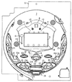
まず、遊技機の一例であるパチンコ遊技機の全体の構成について説明する。図1はパチンコ遊技機を正面からみた正面図、図2は遊技盤の前面を示す正面図である。なお、以下の実施の形態では、パチンコ遊技機を例に説明を行なうが、本発明による遊技機はパチンコ遊技機に限られず、スロット機などの他の遊技機に適用することもできる。 First, the overall configuration of a pachinko gaming machine that is an example of a gaming machine will be described. FIG. 1 is a front view of a pachinko gaming machine as viewed from the front, and FIG. 2 is a front view showing the front of the game board. In the following embodiments, a pachinko gaming machine will be described as an example. However, the gaming machine according to the present invention is not limited to a pachinko gaming machine, and can be applied to other gaming machines such as a slot machine.
パチンコ遊技機1は、縦長の方形状に形成された外枠(図示せず)と、外枠の内側に開閉可能に取り付けられた遊技枠とで構成される。また、パチンコ遊技機1は、遊技枠に開閉可能に設けられている額縁状に形成されたガラス扉枠2を有する。遊技枠は、外枠に対して開閉自在に設置される前面枠(図示せず)と、機構部品等が取り付けられる機構板と、それらに取り付けられる種々の部品(後述する遊技盤を除く。)とを含む構造体である。
The
図1に示すように、パチンコ遊技機1は、額縁状に形成されたガラス扉枠2を有する。ガラス扉枠2の下部表面には打球供給皿(上皿)3がある。打球供給皿3の下部には、打球供給皿3に収容しきれない遊技球を貯留する余剰球受皿4と遊技球を発射する打球操作ハンドル(操作ノブ)5が設けられている。ガラス扉枠2の背面には、遊技盤6が着脱可能に取り付けられている。なお、遊技盤6は、それを構成する板状体と、その板状体に取り付けられた種々の部品とを含む構造体である。また、遊技盤6の前面には遊技領域7が形成されている。
As shown in FIG. 1, the
遊技領域7の中央付近には、それぞれが演出用の飾り図柄を可変表示する複数の可変表示部を含む可変表示装置(飾り図柄表示装置)9が設けられている。可変表示装置9には、たとえば「左」、「中」、「右」の3つの可変表示部(図柄表示エリア)がある。また、可変表示装置9には、始動入賞口14に入った有効入賞球数すなわち始動記憶数を表示する4つの特別図柄始動記憶表示エリア(始動記憶表示エリア)18が設けられている。有効始動入賞がある毎に、表示色が変化する(たとえば青色表示から赤色表示に変化)始動記憶表示エリアを1増やす。そして、可変表示装置9の可変表示が開始される毎に、表示色が変化している始動記憶数表示エリアを1減らす(すなわち表示色をもとに戻す)。この例では、図柄表示エリアと始動記憶表示エリアとが区分けされて設けられているので、可変表示中も始動記憶数が表示された状態にすることができる。なお、始動記憶表示エリアを図柄表示エリアの一部に設けるようにしてもよい。また、可変表示中は始動記憶数の表示を中断するようにしてもよい。また、この例では、始動記憶表示エリアが可変表示装置9に設けられているが、始動記憶数を表示する表示器(特別図柄始動記憶表示器)を可変表示装置9とは別個に設けてもよい。
Near the center of the
可変表示装置9の上部には、識別情報としての特別図柄を可変表示する特別図柄表示器(特別図柄表示装置)8が設けられている。この実施の形態では、特別図柄表示器8は、たとえば0〜9の数字を可変表示可能な簡易で小型の表示器(たとえば7セグメントLED)で実現されている。特別図柄表示器8は、遊技者に特定の停止図柄を把握しづらくさせるために、0〜99など、より多種類の数字を可変表示するように構成されていてもよい。可変表示装置9は、特別図柄表示器8による特別図柄の可変表示期間中に、装飾用(演出用)の図柄としての飾り図柄の可変表示を行なう。なお、飾り図柄の可変表示を行なう可変表示装置9は、演出制御基板に搭載されている演出制御用マイクロコンピュータ100によって制御される。さらに、可変表示装置9の左側には、遊技演出に用いられる可動部材としてのハンマ151が設けられている。ハンマ151は、可動部152を支点として右方向に倒れ、可変表示装置9に表示される飾り図柄のうち最も左側の飾り図柄を叩くような演出を行なうことができる。
A special symbol display (special symbol display device) 8 that variably displays a special symbol as identification information is provided on the
また、パチンコ遊技機1は、遊技の進行中に遊技者が操作可能な操作スイッチ81を備える。たとえば、操作スイッチ81が操作(押下)されると、可動部材としてのハンマ151が動作する。なお、本実施の形態においては、操作手段として押しボタン式の操作スイッチを説明するが、これに限らず、左右上下方向に指示可能な十字キー等、遊技者からの操作を受付けて、受付けた操作に応じた信号を出力するものであればよい。
In addition, the
可変表示装置9の下方には、始動入賞口14としての可変入賞球装置15が設けられている。始動入賞口14に入った入賞球は、遊技盤6の背面に導かれ、始動口スイッチ14aによって検出される。また、始動入賞口14の下部には開閉動作を行なう可変入賞球装置15が設けられている。可変入賞球装置15は、ソレノイド16によって開状態とされる。
Below the
可変入賞球装置15の下部には、特定遊技状態(大当り状態)においてソレノイド21によって開状態とされる開閉板を用いた可変入賞球装置20が設けられている。可変入賞球装置20は大入賞口を開閉する手段である。可変入賞球装置20に入賞し遊技盤6の背面に導かれた入賞球のうち一方(V入賞領域:特別領域)に入った入賞球はVカウントスイッチ22で検出され、他方の領域に入った遊技球はカウントスイッチ23で検出される。遊技盤6の背面には、大入賞口内の経路を切り換えるためのソレノイド21Aも設けられている。
A variable winning
遊技球がゲート32を通過しゲートスイッチ32aで検出されると、普通図柄表示器10の表示の可変表示が開始される。この実施の形態では、左右のランプ(点灯時に図柄が視認可能になる)が交互に点灯することによって可変表示が行なわれ、たとえば、可変表示の終了時に右側のランプが点灯すれば当りとなる。そして、普通図柄表示器10における停止図柄が所定の図柄(当り図柄)である場合に、可変入賞球装置15が所定回数、所定時間だけ開状態になる。普通図柄表示器10の近傍には、ゲート32を通過した入賞球数を表示する4つのLEDによる表示部を有する普通図柄始動記憶表示器41が設けられている。ゲート32への遊技球の通過がある毎に、普通図柄始動記憶表示器41は点灯するLEDを1増やす。そして、普通図柄表示器10の可変表示が開始される毎に、点灯するLEDを1減らす。
When the game ball passes through the
遊技盤6には、複数の入賞口29,30,33,39が設けられ、遊技球の入賞口29,30,33,39への入賞は、それぞれ入賞口スイッチ29a,30a,33a,39aによって検出される。各入賞口29,30,33,39は、遊技媒体を受け入れて入賞を許容する領域として遊技盤6に設けられる入賞領域を構成している。なお、始動入賞口14や大入賞口も、遊技媒体を受け入れて入賞を許容する入賞領域を構成する。遊技領域7の左右周辺には、遊技中に点滅表示される装飾ランプ25が設けられ、下部には、入賞しなかった遊技球を吸収するアウト口26がある。また、遊技領域7の外側の左右上部には、効果音を発する2つのスピーカ27が設けられている。遊技領域7の外周には、天枠ランプ28a、左枠ランプ28bおよび右枠ランプ28cが設けられている。さらに、遊技領域7における各構造物(大入賞口等)の周囲には装飾LEDが設置されている。天枠ランプ28a、左枠ランプ28bおよび右枠ランプ28cおよび装飾用LEDは、遊技機に設けられている装飾発光体の一例である。
The
そして、この例では、左枠ランプ28bの近傍に、賞球払出中に点灯する賞球LED51が設けられ、天枠ランプ28aの近傍に、補給球が切れたときに点灯する球切れLED52が設けられている。上記のように、この実施の形態のパチンコ遊技機1には、発光体としてのランプやLEDが各所に設けられている。さらに、プリペイドカードが挿入されることによって球貸しを可能にするプリペイドカードユニット(以下、「カードユニット」という。)50が、パチンコ遊技機1に隣接して設置されている。
In this example, a prize ball LED 51 that is lit while paying out a prize ball is provided in the vicinity of the
カードユニットには、たとえば、使用可能状態であるか否かを示す使用可表示ランプ、カードユニットがいずれの側のパチンコ遊技機1に対応しているのかを示す連結台方向表示器、カードユニット内にカードが投入されていることを示すカード投入表示ランプ、記録媒体としてのカードが挿入されるカード挿入口、およびカード挿入口の裏面に設けられているカードリーダライタの機構を点検する場合にカードユニットを解放するためのカードユニット錠が設けられている。
The card unit includes, for example, a use indicator lamp that indicates whether or not the card unit is in a usable state, a connection table direction indicator that indicates which side of the
遊技者の操作により打球発射装置から発射された遊技球は、打球レールを通って遊技領域7に入り、その後、遊技領域7を下りてくる。遊技球が始動入賞口14に入り始動口スイッチ14aで検出されると、図柄の可変表示を開始できる状態であれば、特別図柄表示器8において特別図柄が可変表示(変動)を始める。図柄の可変表示を開始できる状態でなければ、始動記憶数を1増やす。
A game ball launched from the ball striking device by the player's operation enters the
特別図柄表示器8における特別図柄の可変表示は、一定時間が経過したときに停止する。停止時の特別図柄の組合せが大当り図柄(特定表示結果)であると、大当り遊技状態に移行する。すなわち、可変入賞球装置20が、一定時間経過するまで、または、所定個数(たとえば10個)の遊技球が入賞するまで開放する。そして、可変入賞球装置20の開放中に遊技球がV入賞領域に入賞しVカウントスイッチ22で検出されると、継続権が発生し可変入賞球装置20の開放が再度行なわれる。継続権の発生は、所定回数(たとえば15ラウンド)許容される。
The variable display of the special symbol on the special
停止時の特別図柄表示器8における特別図柄が確率変動を伴う大当り図柄(確変図柄)の組合せである場合には、次に大当りとなる確率が高くなる。すなわち、確変状態という遊技者にとってさらに有利な状態となる。
If the special symbol on the
遊技球がゲート32を通過すると、普通図柄表示器10において普通図柄が可変表示される状態になる。また、普通図柄表示器10における停止図柄が所定の図柄(当り図柄)である場合に、可変入賞球装置15が所定時間だけ開状態になる。さらに、確変状態では、普通図柄表示器10における停止図柄が当り図柄になる確率が高められるとともに、可変入賞球装置15の開放時間と開放回数が高められる。すなわち、可変入賞球装置15の開放時間と開放回数は、普通図柄の停止図柄が当り図柄である場合や、特別図柄の停止図柄が確変図柄である場合等に高められ、遊技者にとって不利な状態から有利な状態に変化する。なお、開放回数が高められることは、閉状態から開状態になることも含む概念である。
When the game ball passes through the
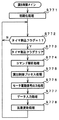
次に、パチンコ遊技機1の裏面の構造について図3を参照して説明する。図3は、遊技機を裏面から見た背面図である。
Next, the structure of the back surface of the
図3に示すように、遊技機裏面側では、可変表示装置9を制御する演出制御用マイクロコンピュータ100が搭載された演出制御基板80を含む可変表示制御ユニット49、遊技制御用マイクロコンピュータ等が搭載された遊技制御基板(主基板)31が設置されている。また、球払出制御を行なう払出制御用マイクロコンピュータ等が搭載された払出制御基板37が設置されている。なお、演出制御マイクロコンピュータは、遊技盤6に設けられている可変表示装置9を制御するとともに、ランプ制御基板に搭載されているランプ制御用マイクロコンピュータに、各種装飾LED、普通図柄始動記憶表示器41、装飾ランプ25、枠側に設けられている天枠ランプ28a、左枠ランプ28bおよび右枠ランプ28cを点灯制御させ、音声制御基板に搭載されている音制御用マイクロコンピュータ701に、スピーカ27からの音発生を制御させる。
As shown in FIG. 3, on the back side of the gaming machine, a variable
なお、この実施の形態では、演出制御マイクロコンピュータは、ランプ制御基板に搭載されているランプ制御用マイクロコンピュータおよび音声制御基板に搭載されている音制御用マイクロコンピュータ701に制御コマンドを送信し、ランプ制御用マイクロコンピュータ351および音制御用マイクロコンピュータ701が、演出制御マイクロコンピュータからの制御コマンドに従って各種ランプ・LEDおよびスピーカ27を制御するが、ランプ制御基板および音声制御基板には、マイクロコンピュータが搭載されていない構成であってもよい。
In this embodiment, the effect control microcomputer transmits a control command to the lamp control microcomputer mounted on the lamp control board and the
さらに、DC30V、DC21V、DC12VおよびDC5Vを作成する電源回路が搭載された電源基板910やタッチセンサ基板91が設けられている。電源基板910は、大部分が主基板31と重なっているが、主基板31に重なることなく外部から視認可能に露出した露出部分がある。この露出部分には、遊技機1における主基板31および各電気部品制御基板(ランプ制御基板、音声制御基板、演出制御基板80および払出制御基板37)や遊技機に設けられている各電気部品(電力が供給されることによって動作する部品)への電力供給を実行あるいは遮断するための電力供給許可手段としての電源スイッチが設けられている。さらに、露出部分における電源スイッチの内側(基板内部側)には、交換可能なヒューズが設けられている。
Further, a
なお、電気部品制御基板には、電気部品制御用マイクロコンピュータを含む電気部品制御手段が搭載されている。電気部品制御手段は、遊技制御手段等からのコマンドとしての指令信号(制御信号)に従って遊技機に設けられている電気部品(遊技用装置:球払出装置97、可変表示装置9、ランプやLEDなどの発光体、スピーカ27等)を制御する。以下、主基板31を電気部品制御基板に含めて説明を行なうことがある。その場合には、電気部品制御基板に搭載される電気部品制御手段は、遊技制御手段と、遊技制御手段等からの指令信号に従って遊技機に設けられている電気部品を制御する手段とのそれぞれを指す。また、主基板31以外のマイクロコンピュータが搭載された基板をサブ基板ということがある。
An electrical component control means including an electrical component control microcomputer is mounted on the electrical component control board. The electrical component control means is an electrical component (game device:
遊技機裏面において、上方には、各種情報を遊技機外部に出力するための各端子を備えたターミナル基板160が設置されている。ターミナル基板160には、少なくとも、球切れ検出スイッチ167の出力を導入して外部出力するための球切れ用端子、賞球情報(賞球個数信号)を外部出力するための賞球用端子および球貸し情報(球貸し個数信号)を外部出力するための球貸し用端子が設けられている。また、中央付近には、主基板31からの各種情報を遊技機外部に出力するための各端子を備えた情報端子基板(情報出力基板)34が設置されている。
On the back side of the gaming machine, a
貯留タンク38に貯留された遊技球は誘導レール39を通り、カーブ樋を経て払出ケース40Aで覆われた球払出装置に至る。球払出装置の上部には、遊技媒体切れ検出手段としての球切れスイッチ187が設けられている。球切れスイッチ187が球切れを検出すると、球払出装置の払出動作が停止する。球切れスイッチ187は遊技球通路内の遊技球の有無を検出するスイッチであるが、貯留タンク38内の補給球の不足を検出する球切れ検出スイッチ167も誘導レール39における上流部分(貯留タンク38に近接する部分)に設けられている。球切れ検出スイッチ167が遊技球の不足を検知すると、遊技機設置島に設けられている補給機構から遊技機に対して遊技球の補給が行なわれる。
The game balls stored in the
入賞に基づく景品としての遊技球や球貸し要求に基づく遊技球が多数払出されて打球供給皿3が満杯になると、遊技球は、余剰球通路を経て余剰球受皿4に導かれる。さらに遊技球が払出されると、感知レバー(図示せず)が貯留状態検出手段としての満タンスイッチ(図示せず)を押圧して、貯留状態検出手段としての満タンスイッチがオンする。その状態では、球払出装置内の払出モータの回転が停止して球払出装置の動作が停止するとともに打球発射装置の駆動も停止する。なお、この実施の形態では、電源基板910や払出制御基板37などが遊技枠に設置され、主基板31などが遊技盤6に設置される。
When a large number of game balls as prizes based on winning prizes or game balls based on ball lending requests are paid out and the hitting
図4は、払出ケース40Aで覆われた球払出装置97を示す正面図(図4(A))および断面図(図4(B))である。球払出装置97は、球切れスイッチ187と球払出装置97との間に設置されている通路体の下部に固定されている。通路体は、カーブ樋によって流下方向が左右方向に変換された2列の遊技球を流下させる球通路を有する。球通路の上流側には、球切れスイッチ187が設置されている。なお、実際には、それぞれの球通路に球切れスイッチが設置されている。球切れスイッチ187は、球通路内の遊技球の有無を検出するものであって、球切れスイッチ187が遊技球を検出しなくなると球払出装置97における払出モータ(図4において図示せず)の回転を停止して遊技球の払出が不動化される。また、球切れスイッチ187は、球通路に27〜28個の遊技球が存在することを検出できるような位置に係止片によって係止されている。
FIG. 4 is a front view (FIG. 4 (A)) and a cross-sectional view (FIG. 4 (B)) showing the
球払出装置97において、ステッピングモータによる払出モータ(図示せず)がたとえばカムを回転させることによって、賞球または球貸し要求に基づく遊技球を1個ずつ払出す。また、球払出装置97の下方には、たとえば近接スイッチによる払出個数カウントスイッチ301が設けられている。球払出装置97から1個の遊技球が落下する毎に、払出個数カウントスイッチ301がオンする。すなわち、払出個数カウントスイッチ301は、球払出装置97から実際に払出された遊技球を検出する。従って、払出制御用マイクロコンピュータは、払出個数カウントスイッチ301の検出信号によって、実際に払出された遊技球の数を計数することができる。この例では、払出個数カウントスイッチ301は、払出された賞球および貸し球の両方を検出する。すなわち、賞球の払出しと貸し球の払出しが同一の検出手段によって検出される。よって、部品点数を減らすことができ、遊技機のコストを低減させることができる。ただし、賞球の払出しと貸し球の払出しとが別個の検出手段によって検出される構成としてもよい。
In the
この実施の形態では、球払出装置97は、賞球払出と球貸しとを共に行なうように構成されている。しかし、賞球払出を行なう球払出装置と球貸しを行なう球払出装置が別個に設けられていてもよい。別個に設けられている場合には、賞球払出を行なう球払出装置と球貸しを行なう球払出装置とで払出手段が構成される。さらに、たとえば、カムまたはスプロケットの回転方向を変えて賞球払出と球貸しとを分けるように構成されていてもよいし、本実施の形態において例示する球払出装置97(モータによってカムを回転させる構成)以外のどのような構造の球払出装置を用いてもよい。
In this embodiment, the
図5は、ハンマ151の駆動装置の構造を示す斜視図である。ハンマ151は、駆動源となるモータ150によって駆動される。モータ150の回転力は、モータ150の回転軸に嵌合しているギア152に伝えられ、さらに、ギア152と噛み合うギア153に伝えられる。ギア153が嵌合している回転軸157には、切欠部156aが設けられた平板156が嵌合されている。また、回転軸157の端部には、ギア153の回転方向と同じ方向にハンマ151が回転するように、回転軸157の軸方向に対して直交する方向に、ハンマ151のアーム158が嵌合部材159を用いて嵌合されている。
FIG. 5 is a perspective view showing the structure of the driving device of the
モータ150の回転力によって、図5(A)に示す矢印方向にギア152が回転すると、回転力が伝えられるギア153が嵌合している回転軸157の回転に応じて平板156およびハンマ151が回転する。そして、ハンマ151が、図5(A)に示す位置から図5(B)に示す位置まで移動される。平板156に形成されている切欠部156aは、ハンマ151が図5(A)に示す位置であるときはセンサ154によって感知され、ハンマ151が図5(B)に示す位置であるときはセンサ155によって感知される。
When the
すなわち、センサ154,155は、ハンマ151の位置を検出して検出結果を検出信号として出力する位置検出手段の一例である。センサ154,155は、それぞれ、ハンマ151の回転可能範囲の両端を検知可能な位置に設置される。ハンマ151の回転可能範囲は、たとえば90度である。
That is, the
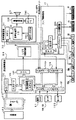
図6は、主基板31における回路構成の一例を示すブロック図である。なお、図6には、払出制御基板37および演出制御基板80等も示されている。主基板31には、プログラムに従ってパチンコ遊技機1を制御する基本回路(遊技制御手段に相当)53と、ゲートスイッチ32a、始動口スイッチ14a、Vカウントスイッチ22、カウントスイッチ23、入賞口スイッチ29a,30a,33a,39a、およびクリアスイッチ921からの信号を基本回路53に与える入力ドライバ回路58と、可変入賞球装置15を開閉するソレノイド16、可変入賞球装置20を開閉するソレノイド21および大入賞口内の経路を切り換えるためのソレノイド21Aを基本回路53からの指令に従って駆動するソレノイド回路59とが搭載されている。
FIG. 6 is a block diagram illustrating an example of a circuit configuration in the
なお、ゲートスイッチ32a、始動口スイッチ14a、Vカウントスイッチ22、カウントスイッチ23、入賞口スイッチ29a,30a,33a,39a等のスイッチは、センサと称されているものでもよい。すなわち、遊技球を検出できる遊技媒体検出手段(この例では遊技球検出手段)であれば、その名称を問わない。入賞検出を行なう始動口スイッチ14a、Vカウントスイッチ22、カウントスイッチ23、および入賞口スイッチ29a,30a,33a,39aの各スイッチは、入賞領域への遊技球の入賞を検出する入賞検出手段でもある。本実施の形態においては、入賞検出手段により入賞領域への遊技球の入賞が検出されたときに、払出条件が成立したものと判定される。なお、入賞検出手段は、複数の入賞口に別個に入賞したそれぞれの遊技球をまとめて検出するものであってもよい。また、ゲート32のような通過ゲートであっても、賞球の払出しが行なわれるものであれば、通過ゲートへ遊技球が進入することが入賞になり、通過ゲートに設けられているスイッチ(たとえばゲートスイッチ32a)が入賞検出手段になる。さらに、この実施の形態では、V入賞領域に入賞した遊技球はVカウントスイッチ22のみで検出されるので、大入賞口に入賞した遊技球数は、Vカウントスイッチ22による検出数とカウントスイッチ23による検出数との和になる。しかし、V入賞領域に入賞した遊技球が、Vカウントスイッチ22で検出されるとともにカウントスイッチ23でも検出されるようにしてもよい。その場合には、大入賞口に入賞した遊技球数は、カウントスイッチ23による検出数に相当する。
It should be noted that the
また、基本回路53から与えられるデータに従って、大当りの発生を示す大当り情報、可変表示装置9における図柄の可変表示開始に利用された始動入賞球の個数を示す有効始動情報、確率変動が生じたことを示す確変情報等の情報出力信号をホールコンピュータ等の外部装置に対して出力する情報出力回路64が搭載されている。
Further, according to the data given from the
基本回路53は、ゲーム制御(遊技進行制御)用のプログラム等を記憶するROM54、ワークメモリとして使用される記憶手段(変動データを記憶する遊技制御用記憶手段)としてのRAM55、およびプログラムに従って制御動作を行なうCPU56を有する遊技制御用マイクロコンピュータ560と、I/Oポート部57とを含む。この実施の形態では、ROM54およびRAM55は遊技制御用マイクロコンピュータ560に内蔵されている。すなわち、遊技制御用マイクロコンピュータ560は、1チップマイクロコンピュータである。1チップマイクロコンピュータは、少なくともRAM55が内蔵されていればよく、ROM54は外付けであっても内蔵されていてもよい。また、I/Oポート部57は、1チップマイクロコンピュータに内蔵されていてもよい。
The
なお、遊技制御用マイクロコンピュータ560においてCPU56がROM54に格納されているプログラムに従って制御を実行するので、以下、遊技制御用マイクロコンピュータ560が実行する(または、処理を行なう)ということは、具体的には、遊技制御用マイクロコンピュータ560がプログラムに従って制御を実行することである。このことは、主基板31以外の他の基板に搭載されているマイクロコンピュータについても同様である。また、遊技制御手段は、遊技制御用マイクロコンピュータ560を含む基本回路53で実現されている。
In the
また、RAM55は、その一部または全部が電源基板910において作成されるバックアップ電源によってバックアップされている不揮発性記憶手段としてのバックアップRAMである。すなわち、遊技機に対する電力供給が停止しても、所定期間(バックアップ電源としてのコンデンサが放電してバックアップ電源が電力供給不能になるまで)は、RAM55の一部または全部の内容は保存される。特に、少なくとも、遊技状態すなわち遊技制御手段の制御状態に応じたデータ(特別図柄プロセスフラグ等)と未払出賞球数を示すデータは、バックアップRAMに保存される。なお、遊技制御手段の制御状態に応じたデータとは、停電等が生じた後に復旧した場合に、そのデータに基づいて、制御状態を停電等の発生前に復旧させるために必要なデータである。また、この実施の形態では、RAM55の全部が、電源バックアップされているとする。
The RAM 55 is a backup RAM as a non-volatile storage means that is partially or entirely backed up by a backup power source created on the
基本回路53の入力ポートには、払出制御基板37から、RAMの内容をクリアすることを指示するためのクリアスイッチが操作されたことを示すクリア信号、電源基板910からの電源電圧が所定値以下に低下したことを示す電源断信号、および遊技制御用マイクロコンピュータ560に対する遊技制御用許容信号(CPUを動作可能状態にさせるための信号)として用いられるリセット確認信号が入力される。
At the input port of the
遊技球を打撃して発射する打球発射装置は払出制御基板37上の回路によって制御される発射モータ94を含み、発射モータ94が回転することによって遊技球を遊技領域7に向けて発射する。発射モータ94を駆動するための駆動信号は、タッチセンサ基板91を介して発射モータ94に伝達される。そして、遊技者が操作ノブ(打球ハンドル)5に触れていることはタッチセンサで検出され、タッチセンサからの信号がタッチセンサ基板91に搭載されているタッチセンサ回路(遊技者が操作ノブ5に触れているか否かを検出するための検出回路等を含む回路)を介して払出制御基板37に伝達される。払出制御基板37上の回路は、タッチセンサ回路からの信号がオフ状態を示している場合には、発射モータ94の駆動を停止する。なお、操作ノブ5には、弾発力を調節するものであり、遊技者が接触する部分であるタッチリングが組み付けられている。タッチセンサ基板91は、遊技機において、タッチリングと払出制御基板37との間に配置され、かつ、タッチリングの近傍に配置されている。具体的には、タッチリングとタッチセンサ基板91との間の配線長は、タッチセンサ基板91と払出制御基板37との間の配線長よりも短い。
The hitting ball launching device for hitting and launching the game ball includes a
なお、この実施の形態では、演出制御基板80に搭載されている演出制御手段(演出制御用マイクロコンピュータ100で構成される。)が、中継基板77を介して遊技制御用マイクロコンピュータ560からの演出制御コマンドを受信し、特別図柄を可変表示する可変表示装置9の表示制御を行なう。また、ランプ制御基板35に搭載されているランプ制御手段(ランプ制御用マイクロコンピュータで構成される。)が、遊技盤6に設けられている普通図柄表示器10、普通図柄始動記憶表示器41および装飾ランプ25の表示制御を行なうとともに、枠側に設けられている天枠ランプ28a、左枠ランプ28bおよび右枠ランプ28cの表示制御を行なう。
In this embodiment, the effect control means (configured by the effect control microcomputer 100) mounted on the
また、この実施の形態で用いられている遊技制御用マイクロコンピュータ560は、ソフトウェアで割込禁止に設定できないマスク不能割込(NMI)を発生させるために使用されるマスク不能割込端子(NMI端子)と、遊技制御用マイクロコンピュータ560の外部から割込(外部割込;ソフトウェアで割込禁止にできるマスク可能割込)を発生させるために使用される割込端子(INT端子)とを有する。しかし、この実施の形態では、マスク不能割込および外部割込を使用しない。そこで、NMI端子およびINT端子を、抵抗を介してVcc(+5V)にプルアップしておく。従って、NMI端子およびINT端子の入力レベルは常にハイレベルになり、端子オープン状態に場合に比べて、ノイズ等によってNMI端子およびINT端子の入力レベルが立ち下がって割込発生状態になる可能性が低減する。
Further, the
図7は、払出制御基板37および球払出装置97などの払出に関連する構成要素を示すブロック図である。図7に示すように、払出制御基板37には、払出制御用CPU371を含む払出制御用マイクロコンピュータ(電気部品制御用マイクロコンピュータの一例)370が搭載されている。この実施の形態では、払出制御用マイクロコンピュータ370は、1チップマイクロコンピュータであり、少なくともRAMが内蔵されている。払出制御用マイクロコンピュータ370、RAM(図示せず)、払出制御用プログラムを格納したROM(図示せず)およびI/Oポート等は、払出制御手段を構成する。すなわち、払出制御手段は、払出制御用マイクロコンピュータ370、RAMおよびROMを有する払出制御用マイクロコンピュータ370と、I/Oポートとで実現される。また、I/Oポートは、払出制御用マイクロコンピュータ370に内蔵されていてもよい。払出制御用マイクロコンピュータ370におけるRAMの少なくとも一部は、電源基板910に搭載されているバックアップ電源によって電源バックアップされている。この実施の形態では、全てのRAM領域が電源バックアップされているとする。よって、遊技機に対して電力供給がなされていないときにも、所定期間(バックアップ電源としてのコンデンサが放電してバックアップ電源が電力供給不能になるまで)は、RAMの記憶内容は保存される。
FIG. 7 is a block diagram showing components related to payout, such as the
球切れスイッチ187、満タンスイッチ48および払出個数カウントスイッチ301からの検出信号は、中継基板72を介して払出制御基板37のI/Oポート372fに入力される。また、払出モータ位置センサ295からの検出信号は、中継基板72を介して払出制御基板37のI/Oポート372eに入力される。払出モータ位置センサ295は、払出モータ289の回転位置を検出するための発光素子(LED)と受光素子とによるセンサであり、遊技球が詰まったこと、すなわちいわゆる球噛みを検出するために用いられる。払出制御基板37に搭載されている払出制御用マイクロコンピュータ370は、球切れスイッチ187からの検出信号が球切れ状態を示している場合や、満タンスイッチ48からの検出信号が満タン状態を示している場合には、球払出処理を停止する。さらに、満タンスイッチ48からの検出信号が満タン状態を示していると、打球発射装置からの球発射を停止させる。
Detection signals from the ball break
入賞口への遊技球の入賞があると、主基板31の出力回路67から、払出指令信号として、払出すべき賞球個数を示す賞球個数信号および賞球個数信号の取り込み(受信)を要求する賞球REQ信号(取込要求信号)が出力(送信)される。具体的には、オン状態になる。賞球個数信号は、4ビットのデータ(2進4桁のデータ)によって構成され、4本の信号線によって出力される。なお、信号のオン状態すなわち出力状態は、信号が有意である状態であり、オン状態になることは、信号を受ける側に対してその信号に基づく何らかの処理を開始することを指令することを意味する。たとえば、賞球個数を示す賞球個数信号および賞球REQ信号がオン状態になるということは、払出制御用マイクロコンピュータ370に対して、賞球個数信号が示す払出数を認識するように指令することを意味する。また、信号を出力することによってオン状態とし、信号出力を停止することによってオフ状態としてもよいが、オン状態にするときにはオン状態に応じた信号を出力し、オフ状態にするときにはオフ状態に応じた信号を出力することによって、オン状態とオフ状態とを切り換えてもよい。
When there is a winning game ball at the winning opening, the
賞球REQ信号および賞球個数信号は、入力回路373Aを介してI/Oポート372eに入力される。払出制御用マイクロコンピュータ370は、I/Oポート372eを介して賞球個数信号を入力すると、賞球個数信号が示す個数の遊技球を払出すために球払出装置97を駆動する制御を行なう。なお、主基板31の出力回路67からは、主基板31が接続されていることを示す接続確認信号も出力される。また、賞球REQ信号および賞球個数信号は、払出数を指定する払出指令信号に相当する。
The prize ball REQ signal and the prize ball number signal are input to the I /
また、払出制御基板37には、電源基板910から、電源電圧が所定値以下の低下したことを示す電源断信号、およびRAMの内容をクリアするためのクリアスイッチが操作されたことを示すクリア信号とが、入力ポート372gに入力される。電源断信号とクリア信号とは、入力ポート372gを介して払出制御用マイクロコンピュータ371に入力されるとともに、出力回路373Bを介して主基板31に出力される。そして、主基板31において、入力回路68およびI/Oポート57を介して遊技制御用マイクロコンピュータ560に入力される。また、払出制御用マイクロコンピュータ371には、電源基板910から、当該払出制御用マイクロコンピュータ371に対する払出制御用許容信号(CPUを動作可能状態にさせるための信号)として用いられるリセット信号が入力される。
The
また、前述したリセット確認信号は、払出制御用マイクロコンピュータ370から出力ポート372hおよび出力回路373Bを介して、主基板31に出力される。そして、主基板31において、入力回路68およびI/Oポート57を介して遊技制御用マイクロコンピュータ560に入力される。
The reset confirmation signal described above is output from the
払出制御用マイクロコンピュータ370は、出力ポート372bを介して、賞球払出数を示す賞球情報信号および貸し球数を示す球貸し個数信号をターミナル基板(枠用外部端子基板と盤用外部端子基板とを含む)160に出力する。なお、出力ポート372bの外側に、ドライバ回路が設置されているが、図7では記載省略されている。
The
また、払出制御用マイクロコンピュータ370は、出力ポート372cを介して、7セグメントLEDによるエラー表示用LED374にエラー信号を出力する。さらに、出力ポート372bを介して、点灯/消灯を指示するための信号を賞球LED51および球切れLED52に出力する。なお、払出制御基板37の入力ポート372fには、エラー状態を解除するためのエラー解除スイッチ375からの検出信号が入力される。エラー解除スイッチ375は、ソフトウェアリセットによってエラー状態を解除するために用いられる。
Also, the
さらに、払出制御用マイクロコンピュータ370からの払出モータ289への駆動信号は、出力ポート372aおよび中継基板72を介して球払出装置97の払出機構部分における払出モータ289に伝えられる。なお、出力ポート372aの外側に、ドライバ回路(モータ駆動回路)が設置されているが、図7では記載省略されている。また、払出制御用マイクロコンピュータ370からの発射モータ94への駆動信号は、出力ポート372aおよびタッチセンサ基板91を介して発射モータ94に伝えられる。
Further, a drive signal from the
遊技機に隣接して設置されているカードユニット50には、カードユニット制御用マイクロコンピュータが搭載されている。また、カードユニット50には、使用可表示ランプ、連結台方向表示器、カード投入表示ランプおよびカード挿入口が設けられている。インタフェース基板(中継基板)66には、打球供給皿3の近傍に設けられている度数表示LED60、球貸し可LED61、球貸しスイッチ62および返却スイッチ63が接続される。
A card unit control microcomputer is mounted on the card unit 50 installed adjacent to the gaming machine. In addition, the card unit 50 is provided with a usable display lamp, a connecting table direction indicator, a card insertion display lamp, and a card insertion slot. A
インタフェース基板66からカードユニット50には、遊技者の操作に応じて、球貸しスイッチ62が操作されたことを示す球貸しスイッチ信号および返却スイッチ63が操作されたことを示す返却スイッチ信号が与えられる。また、カードユニット50からインタフェース基板66には、プリペイドカードの残高を示すカード残高表示信号および球貸し可表示信号が与えられる。カードユニット50と払出制御基板37の間では、接続信号(VL信号)、ユニット操作信号(BRDY信号)、球貸し要求信号(BRQ信号)、球貸し完了信号(EXS信号)およびパチンコ機動作信号(PRDY信号)が入力ポート372fおよび出力ポート372dを介して送受信される。カードユニット50と払出制御基板37の間には、インタフェース基板66が介在している。よって、接続信号(VL信号)等の信号は、図7に示すように、インタフェース基板66を介してカードユニット50と払出制御基板37の間で送受信されることになる。
A card lending switch signal indicating that the ball lending switch 62 has been operated and a return switch signal indicating that the return switch 63 has been operated are provided to the card unit 50 from the interface board 66 in accordance with the player's operation. . Further, a card balance display signal indicating a prepaid card balance and a ball lending display signal are given from the card unit 50 to the interface board 66. Between the card unit 50 and the
パチンコ遊技機1の電源が投入されると、払出制御基板37に搭載されている払出制御用マイクロコンピュータ370は、カードユニット50にPRDY信号を出力する。また、カードユニット制御用マイクロコンピュータは、電源が投入されると、VL信号を出力する。払出制御用マイクロコンピュータ370は、VL信号の入力状態によってカードユニット50の接続状態/未接続状態を判定する。カードユニット50においてカードが受付けられ、球貸しスイッチが操作され球貸しスイッチ信号が入力されると、カードユニット制御用マイクロコンピュータは、払出制御基板37にBRDY信号を出力する。この時点から所定の遅延時間が経過すると、カードユニット制御用マイクロコンピュータは、払出制御基板37にBRQ信号を出力する。
When the power of the
そして、払出制御用マイクロコンピュータ370は、カードユニット50に対するEXS信号を立ち上げ、カードユニット50からのBRQ信号の立ち下がりを検出すると、払出モータ289を駆動し、所定個の貸し球を遊技者に払出す。そして、払出が完了したら、払出制御用マイクロコンピュータ370は、カードユニット50に対するEXS信号を立ち下げる。その後、カードユニット50からのBRDY信号がオン状態でないことを条件に、遊技制御手段から払出指令信号を受けると賞球払出制御を実行する。
Then, the
カードユニット50で用いられる電源電圧AC24Vは払出制御基板37から供給される。すなわち、カードユニット50に対する電源基板910からの電力供給は、払出制御基板37およびインタフェース基板66を介して行なわれる。この例では、インタフェース基板66内に配されているカードユニット50に対するAC24Vの電源供給ラインに、カードユニット50を保護するためのヒューズが設けられ、カードユニット50に所定電圧以上の電圧が供給されることが防止される。
The power supply voltage AC24V used in the card unit 50 is supplied from the
なお、この実施の形態で用いられている払出制御用マイクロコンピュータ370は、マスク不能割込(NMI)を発生させるために使用されるマスク不能割込端子(NMI端子)と、マスク可能割込を発生させるために使用される割込端子(INT端子)とを有する。しかし、この実施の形態では、マスク不能割込および外部割込を使用しない。そこで、NMI端子およびINT端子を、抵抗を介してVcc(+5V)にプルアップしておく。
The
また、この実施の形態では、カードユニット50が遊技機とは別体として遊技機に隣接して設置されている場合を例にするが、カードユニット50は遊技機と一体化されていてもよい。また、コイン投入に応じてその金額に応じた遊技球が貸し出されるものであってもよい。 Further, in this embodiment, the case where the card unit 50 is installed adjacent to the gaming machine as a separate body from the gaming machine is taken as an example, but the card unit 50 may be integrated with the gaming machine. . In addition, game balls corresponding to the amount of money may be lent out in accordance with coin insertion.
図8は、演出制御基板80、ランプ制御基板35および音声制御基板70の回路構成例を示すブロック図である。演出制御基板80において、演出制御用マイクロコンピュータ(電気部品制御用マイクロコンピュータの一例)100における演出制御用CPU101は、ROM(図示せず)に格納されたプログラムに従って動作し、中継基板77を介して主基板31から送信される取込信号(演出制御INT信号)に応じて、中継基板77、入力ドライバ102および入力ポート103を介して演出制御コマンドを受信する。また、演出制御用マイクロコンピュータ100は、演出制御コマンドに基づいて、VDP(ビデオディスプレイプロセッサ)109に、LCDを用いた可変表示装置9の表示制御を行なわせる。VDP109は、GCL(グラフィックコントローラLSI)と呼ばれることもある。
FIG. 8 is a block diagram illustrating a circuit configuration example of the
中継基板77には、主基板31から入力された信号(演出制御コマンドを構成する演出制御信号と演出制御INT信号)を演出制御基板80に向かう方向にしか信号を通過させない(演出制御基板80から主基板31への方向には信号を通過させない)信号入力阻止手段としての単方向性回路74が搭載されている。単方向性回路74として、たとえばダイオードやトランジスタが使用される。図8には、ダイオードが例示されている。また、単方向性回路74は、中継基板77を通過する信号線それぞれに設けられる。演出制御基板80からの信号、演出制御基板80に入力される信号(操作スイッチ81の操作に応じた操作信号およびセンサ154,155の検出信号)、および演出制御基板80に接続されるランプ制御基板35および音声制御基板70(主基板31に接続されない基板を周辺基板ともいう。)からの信号は、中継基板77の存在によって、主基板31の遊技制御用マイクロコンピュータ560に伝達されない。従って、遊技制御用マイクロコンピュータ560に対する外部からの信号入力経路が限定され、遊技制御用マイクロコンピュータ560に対して不正信号を送り込む不正行為がなされる可能性を低減できる。また、さらに、中継基板77を、その裏面が視認可能となる態様で取り付けた場合、中継基板77の裏面を容易に視認することができるため、中継基板77から遊技制御用マイクロコンピュータ560へ不正に信号を入力させるようにする不正行為が行なわれたことを容易に発見することができる。
The
なお、本実施の形態においては、単方向性回路74を中継基板77に設けた例について説明したが、これに限らず、単方向性回路74は、主基板31に設けてもよく、また演出制御基板80に設けてもよい。すなわち、単方向性回路74は、遊技制御用マイクロコンピュータ560に対して不正信号が入力されることを防止できる場所に設けられている構成であればよい。
In the present embodiment, the example in which the
演出制御用マイクロコンピュータ100には、入力ポート106を介して、遊技者によって操作される操作スイッチ81からの操作信号、およびセンサ154,155からの検出信号が入力される。また、演出制御用マイクロコンピュータ100は、出力ポート107を介して、ハンマ151を駆動するモータ150に駆動信号を与える。
The
さらに、演出制御用マイクロコンピュータ100は、入出力ポート104を介して音声制御基板70に対して音声制御コマンドを出力する。また、演出制御用マイクロコンピュータ100は、入出力ポート105を介してランプ制御基板35に対してランプ制御コマンドを出力する。
Furthermore, the
ランプ制御基板35において、CPU、ROMおよびRAMを含むランプ制御用マイクロコンピュータ351は、ランプ制御コマンドに応じたROMに格納されている制御データに基づいて普通図柄表示器10およびランプ・LED等を制御する。そして、ランプ制御基板35に搭載されている出力ポート352、ランプドライバ354およびLED駆動回路355を介して、ランプ・LEDが駆動される。なお、ランプ制御コマンドを入力する入力ポートは、ランプ制御用マイクロコンピュータ351に内蔵されている。
In the
また、音声制御基板70において、CPU、ROMおよびRAMを含む音声制御用マイクロコンピュータ701は、音声制御コマンドに応じたROMに格納されている制御データを音声データROM704からから音声合成用IC703に出力させる。音声合成用IC703は、制御データに応じた音声や効果音を発生し増幅回路705に出力する。増幅回路705は、音声合成用IC703の出力レベルを、ボリューム706で設定されている音量に応じたレベルに増幅した音声信号をスピーカ27に出力する。
In the
音声データROM704に格納されている音声制御コマンドに応じた制御データは、所定期間(たとえば飾り図柄の変動期間)における効果音または音声の出力態様を時系列的に示すデータの集まりである。音声合成用IC703は、制御データを入力すると、音声データROM704内の対応するデータに従って音出力制御を行なう。対応するデータに従った音出力制御は、次の音声制御コマンドが音声制御用マイクロコンピュータ701に入力されるまで継続される。そして、音声合成用IC703は、次の音声制御コマンドが入力されると、新た入力した音番号データに対応した音声データROM704内のデータに従って音出力制御を行なう。
The control data corresponding to the voice control command stored in the
なお、ランプ制御コマンドおよび音声制御コマンドは、演出制御用マイクロコンピュータ100とランプ制御用マイクロコンピュータ351および音声制御用マイクロコンピュータ701との間で、双方向通信(コマンド受信側から送信側に応答信号を送信するような通信)によって伝達される。
The lamp control command and the voice control command are transmitted bidirectionally between the
また、図9を用いて後述するように、電源監視回路920からのリセット信号は、ランプ制御基板35に搭載されたランプ制御用マイクロコンピュータ351に入力される。また、電源監視回路920からのリセット信号は、ランプ制御基板35を経由し、さらに演出制御基板80に搭載された入出力ポート104を介して、演出制御用マイクロコンピュータ100に入力される。同様に、電源監視回路920からのリセット信号は、ランプ制御基板35を経由し、音声制御用マイクロコンピュータ701に入力される。
Further, as will be described later with reference to FIG. 9, the reset signal from the power
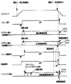
次に、電源基板910の構成を図9のブロック図を参照して説明する。電源基板910には、遊技機内の各電気部品制御基板や機構部品への電力供給を実行または遮断するための電源スイッチ914が設けられている。なお、電源スイッチ914は、遊技機において、電源基板910の外に設けられていてもよい。電源スイッチ914が閉状態(オン状態)では、交流電源(AC24V)がトランス911の入力側(一次側)に印加される。トランス911は、交流電源(AC24V)と電源基板910の内部とを電気的に絶縁するためのものであるが、その出力電圧もAC24Vである。また、トランス911の入力側には、過電圧保護回路としてのバリスタ918が設置されている。
Next, the configuration of the
電源基板910は、電気部品制御基板(主基板31、払出制御基板37および演出制御基板80等)と独立して設置され、遊技機内の各基板および機構部品が使用する電圧を生成する。この例では、AC24V、VSL(DC+30V)、VLP(DC+24V)、VDD(DC+12V)およびVCC(DC+5V)を生成する。また、バックアップ電源(VBB)すなわちバックアップRAMに記憶内容を保持させるための記憶保持手段となるコンデンサ916は、DC+5V(VCC)すなわち各基板上のIC等を駆動する電源のラインから充電される。また、+5Vラインとバックアップ+5V(VBB)ラインとの間に、逆流防止用のダイオード917が挿入される。なお、VSLは、整流平滑回路915において、整流素子でAC24Vを整流昇圧することによって生成される。VSLは、ソレノイド駆動電源となる。また、VLPは、ランプ点灯用の電圧であって、整流回路912において、整流素子でAC24Vを整流することによって生成される。
The
電源電圧生成手段としてのDC−DCコンバータ913は、1つまたは複数のレギュレータIC(図9では2つのレギュレータIC924A,924Bを示す)を有し、VSLに基づいてVDDおよびVCCを生成する。レギュレータIC(スイッチングレギュレータ)924A,924Bの入力側には、比較的大容量のコンデンサ923A,923Bが接続されている。従って、外部からの遊技機に対する電力供給が停止したときに、VSL、VDD、VCC等の直流電圧は、比較的緩やかに低下する。
The DC-
図9に示すように、トランス911から出力されたAC24Vは、そのままコネクタ922Bに供給される。また、VLPは、コネクタ922Cに供給される。VCC、VDDおよびVSLは、コネクタ922A,922B,922Cに供給される。
As shown in FIG. 9, AC24V output from the
コネクタ922Aに接続されるケーブルは、主基板31に接続される。また、コネクタ922Bに接続されるケーブルは、払出制御基板37に接続される。従って、コネクタ922A,922Bには、VBBも供給されている。たとえば、コネクタ922Cに接続されるケーブルは、ランプ制御基板36に接続される。なお、演出制御基板80および音声制御基板70には、ランプ制御基板35を経由して各電圧が供給される。
The cable connected to the connector 922A is connected to the
また、電源基板910には、押しボタン構造のクリアスイッチ921が搭載されている。クリアスイッチ921が押下されるとローレベル(オン状態)のクリア信号が出力され、コネクタ922Bを介して払出制御基板37に送信される。また、クリアスイッチ921が押下されていなければハイレベル(オフ状態)の信号が出力される。なお、クリアスイッチ921は、押しボタン構造以外の他の構成であってもよい。また、クリアスイッチ921は、遊技機において、電源基板910以外に設けられていてもよい。
In addition, a
さらに、電源基板910には、電気部品制御基板に搭載されているマイクロコンピュータに対するリセット信号を作成するとともに、電源断信号を出力する電源監視回路920と、電源監視回路920からのリセット信号を増幅してコネクタ922B,922Cに出力するとともに、電源断信号を増幅してコネクタ922Bに出力する出力ドライバ回路925が搭載されている。なお、本実施の形態においては、ランプ制御基板35を経由したリセット信号が、演出制御用マイクロコンピュータ100および音制御用マイクロコンピュータ701に入力される。しかし、演出制御用マイクロコンピュータ100および音制御用マイクロコンピュータ701へのリセット信号の入力パターンとしてはこれに限るものではない。たとえば、払出制御基板37を経由したリセット信号が入力される入力パターンであってもよい。
Further, the
電源監視回路920は電源断信号を出力する電圧低下監視手段とリセット信号を生成するリセット信号生成手段とを実現する回路である。なお、電圧低下監視手段とリセット信号生成手段とは、各々、別の回路により構成してもよい。電源監視回路920として、市販の停電監視リセットモジュールICを使用することができる。電源監視回路920は、遊技機において用いられる所定電圧(たとえば+24V)が所定値(たとえば+5V)以下になった期間が、あらかじめ決められている時間(たとえば56ms)以上継続すると電源断信号を出力する。具体的には、電源断信号をオン状態(ローレベル)にする。また、電源監視回路920は、たとえば、VCCが+4.5V以下になると、リセット信号をローレベルにする。
The power
なお、電源監視回路920としては、電圧が所定値以下になった期間が所定時間以上継続したか否かを判断することにより、電圧が所定値以下になったか否かを判断するものに限らず、たとえば、ダイオード回路から構成される一般的な全波整流回路を用いて得られるパルスを検出することにより、電圧が所定値以下になったか否かを判断するようにしてもよい。たとえば、全波整流回路により交流波を全波整流して得られるパルスのうち、振幅が所定値以上のパルスをカウントするものであって、所定期間カウントされなかったときに電圧が所定値以下となったと判断するものであってもよい。
The power
電源監視回路920は、遊技機に対する電力供給が停止する際には、電源断信号を出力(ローレベルにする)してから所定期間が経過したことを条件にリセット信号をローレベルにする。所定期間は、主基板31に搭載されている遊技制御用マイクロコンピュータ560および払出制御基板37に搭載されている払出制御用マイクロコンピュータ370が、後述する電源断処理を実行するのに十分な時間である。すなわち、電源監視回路920は、電圧低下信号としての電源断信号を出力した後、遊技制御用マイクロコンピュータ560および払出制御用マイクロコンピュータ370が、電源断処理を実行完了した後に、動作停止信号(リセット信号のローレベル)を出力する。また、遊技機に対する電力供給が開始され、VCCがたとえば+4.5Vを越えるとリセット信号をハイレベルにするのであるが、その場合に、電源断信号が出力されなくなってから(ハイレベルにしてから)所定期間が経過したことを条件にリセット信号をハイレベルにする。従って、リセット信号がハイレベルになったことに応じて各電気部品制御基板(主基板31を含む)に搭載されているマイクロコンピュータがプログラムに従って制御を開始するときに、電源断信号は必ずオフ状態になっている。
When the power supply to the gaming machine is stopped, the power
電源監視回路920からの電源断信号は、払出制御基板37において、入力ポート372gを介して払出制御用マイクロコンピュータ370に入力される(図7参照)。すなわち、払出制御用マイクロコンピュータ370は、入力ポート372gの入力信号を監視することによって遊技機への電力供給の停止の発生を確認することができる。また、主基板31において、電源監視回路920からの電源断信号は、払出制御基板37に搭載されている出力回路373B、および主基板31に搭載されている入力回路68・入力ポート57を介して遊技制御用マイクロコンピュータ560に入力される。すなわち、遊技制御用マイクロコンピュータ560は、入力ポートの入力信号を監視することによって遊技機への電力供給の停止の発生を確認することができる。
The power-off signal from the
一方、電源監視回路920からのリセット信号は、払出制御用マイクロコンピュータ370のリセット端子に入力される(図7参照)。従って、払出制御用マイクロコンピュータ370は、リセット端子の入力状態を監視することによって、払出制御動作の実行状態とするタイミングおよび払出制御動作の停止状態とするタイミングを確認することができる。
On the other hand, the reset signal from the power
なお、電源監視回路920からのリセット信号の入力に応じて払出制御基板37から出力されるリセット確認信号は、払出制御用マイクロコンピュータ370から出力ポート372hおよび出力回路373Bを経由した後、主基板312搭載された入力回路68・入力ポート57を介して遊技制御用マイクロコンピュータ560に入力される。従って、遊技制御用マイクロコンピュータ560は、入力ポート57の入力信号を監視することによって、遊技制御動作の実行状態とするタイミングおよび遊技制御動作の停止状態とするタイミングを確認することができる。
Note that the reset confirmation signal output from the
なお、この実施の形態では、電源監視回路920が所定電位の電源の出力を監視し、外部から遊技機に供給される電力の供給停止に関わる検出条件として、遊技機の外部からの電圧(この実施の形態ではAC24V)から作成された所定の直流電圧が所定値以下になったことを用いたが、検出条件は、それに限られず、外部のからの電力が途絶えたことを検出できるのであれば、他の条件を用いてもよい。たとえば、交流波そのものを監視して交流波が途絶えたことを検出条件としてもよいし、交流波をディジタル化した信号を監視して、ディジタル信号が平坦になったことをもって交流波が途絶えたことを検出条件としてもよい。
In this embodiment, the power
図10および図11は、遊技制御手段における出力ポートの割り当ての例を示す説明図である。図10に示すように、出力ポート0は払出制御基板37に送信される払出制御信号の出力ポートである。また、演出制御基板80に送信される演出制御コマンドの8ビットのデータ(演出制御信号)は出力ポート1から出力される。なお、図10および図11に示された「論理」(たとえば1がオン状態)と逆の論理(たとえば0がオン状態)を用いてもよいが、特に、接続確認信号については、主基板31と払出制御基板37との間の信号線において断線が生じた場合やケーブル外れの場合(ケーブル未接続を含む)等に、払出制御用マイクロコンピュータ370では必ずオフ状態と検知されるように「論理」が定められる。具体的には、一般に、断線やケーブル外れが生ずると信号の受信側ではハイレベルが検知されるので、主基板31と払出制御基板37との間の信号線でのハイレベルが、遊技制御手段における出力ポートにおいてオフ状態になるように「論理」が定められる。従って、必要であれば、主基板31において出力ポートの外側に、信号を論理反転させる出力バッファ回路が設置される。
10 and 11 are explanatory diagrams showing an example of output port assignment in the game control means. As shown in FIG. 10, the
また、出力ポート2から、大入賞口を開閉する可変入賞球装置20を開閉するためのソレノイド(大入賞口扉ソレノイド)21、大入賞口内の経路を切り換えるためのソレノイド(大入賞口内誘導板ソレノイド)21Aおよび可変入賞球装置15を開閉するためのソレノイド(普通電動役物ソレノイド)16に対する駆動信号が出力される。さらに、演出制御基板80に送信される演出制御コマンドについての演出制御INT信号(取込信号)も出力される。演出制御INT信号は、演出制御コマンドの8ビットのデータを取り込む(受信する)ことを演出制御手段に指令するための信号である。
In addition, a solenoid (large winning opening door solenoid) 21 for opening and closing a variable winning
そして、出力ポート3,4から、情報出力回路64を介して情報端子板34やターミナル基板160に至る各種情報出力用信号すなわち制御に関わる情報の出力データが出力される。
Then, various information output signals from the
図12は、遊技制御手段における入力ポートのビット割り当ての例を示す説明図である。図12に示すように、入力ポート0のビット0〜7には、それぞれ、Vカウントスイッチ22、カウントスイッチ23、ゲートスイッチ32a、入賞口スイッチ33a,39a,29a,30a、始動口スイッチ14aの検出信号が入力される。また、入力ポート1のビット0〜2には、それぞれ、払出制御基板37からの電源断信号、払出制御基板37からのクリアスイッチ921の検出信号(クリア信号)、払出制御基板37からのリセット確認信号が入力される。
FIG. 12 is an explanatory diagram showing an example of bit assignment of input ports in the game control means. As shown in FIG. 12,
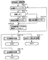
次に遊技機の動作について説明する。図13および図14は、遊技機に対して電力供給が開始され遊技制御用マイクロコンピュータ560へのリセット確認信号がハイレベルになったことに応じて遊技制御用マイクロコンピュータ560が実行するメイン処理を示すフローチャートである。払出制御基板37からのリセット確認信号の入力レベルがハイレベル(オフ状態)になると、遊技制御用マイクロコンピュータ560は、プログラムの内容が正当か否かを確認するための処理であるセキュリティチェック処理を実行した後、ステップS1以降のメイン処理を開始する。メイン処理において、遊技制御用マイクロコンピュータ560は、まず、必要な初期設定を行なう。なお、払出制御基板37からのリセット確認信号の入力レベルがハイレベル(オフ状態)になるタイミングについては、図32のステップS716および図36等を用いて後述する。
Next, the operation of the gaming machine will be described. FIG. 13 and FIG. 14 show the main process executed by the
初期設定処理において、遊技制御用マイクロコンピュータ560は、まず、割込禁止に設定する(ステップS1)。次に、割込モードを割込モード2に設定し(ステップS2)、スタックポインタにスタックポインタ指定アドレスを設定する(ステップS3)。そして、内蔵デバイスレジスタの設定(初期化)を行なう(ステップS4)。
In the initial setting process, the
次いで、遊技制御用マイクロコンピュータ560は、内蔵デバイス(内蔵周辺回路)であるCTC(カウンタ/タイマ)およびPIO(パラレル入出力ポート)の設定(初期化)(ステップS5)を行なった後、RAM55をアクセス可能状態に設定する(ステップS6)。
Next, the
この実施の形態で用いられる遊技制御用マイクロコンピュータ560は、I/Oポート(PIO)およびタイマ/カウンタ回路(CTC)も内蔵している。また、CTCは、2本の外部クロック/タイマトリガ入力CLK/TRG2,3と2本のタイマ出力ZC/TO0,1を備えている。
The
この実施の形態で用いられている遊技制御用マイクロコンピュータ560には、マスク可能な割込のモードとして以下の3種類のモードが用意されている。なお、マスク可能な割込が発生すると、遊技制御用マイクロコンピュータ560は、自動的に割込禁止状態に設定するとともに、プログラムカウンタの内容をスタックにセーブする。
In the
割込モード0:割込要求を行なった内蔵デバイスがRST命令(1バイト)またはCALL命令(3バイト)を遊技制御用マイクロコンピュータ560の内部データバス上に送出する。よって、遊技制御用マイクロコンピュータ560は、RST命令に対応したアドレスまたはCALL命令で指定されるアドレスの命令を実行する。リセット時に、遊技制御用マイクロコンピュータ560は自動的に割込モード0になる。よって、割込モード1または割込モード2に設定したい場合には、初期設定処理において、割込モード1または割込モード2に設定するための処理を行なう必要がある。
Interrupt mode 0: The built-in device that made the interrupt request sends an RST instruction (1 byte) or a CALL instruction (3 bytes) onto the internal data bus of the
割込モード1:割込が受付けられると、常に0038(h)番地に飛ぶモードである。 Interrupt mode 1: When an interrupt is accepted, the mode always jumps to address 0038 (h).
割込モード2:遊技制御用マイクロコンピュータ560の特定レジスタ(Iレジスタ)の値(1バイト)と内蔵デバイスが出力する割込ベクタ(1バイト:最下位ビット0)から合成されるアドレスが、割込番地を示すモードである。すなわち、割込番地は、上位アドレスが特定レジスタの値とされ下位アドレスが割込ベクタとされた2バイトで示されるアドレスである。従って、任意の(飛び飛びではあるが)偶数番地に割込処理を設置することができる。各内蔵デバイスは割込要求を行なうときに割込ベクタを送出する機能を有している。
Interrupt mode 2: The address synthesized from the value (1 byte) of the specific register (I register) of the
よって、割込モード2に設定されると、各内蔵デバイスからの割込要求を容易に処理することが可能になり、また、プログラムにおける任意の位置に割込処理を設置することが可能になる。さらに、割込モード1とは異なり、割込発生要因毎のそれぞれの割込処理を用意しておくことも容易である。上述したように、この実施の形態では、初期設定処理のステップS2において、遊技制御用マイクロコンピュータ560は割込モード2に設定される。
Therefore, when the interrupt
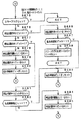
次いで、遊技制御用マイクロコンピュータ560は、入力ポート1を介して入力されるクリアスイッチ921の出力信号の状態を1回だけ確認する(ステップS7)。その確認においてオンを検出した場合には、遊技制御用マイクロコンピュータ560は、通常の初期化処理を実行する(ステップS10〜ステップS15)。クリアスイッチ921がオンである場合(押下されている場合)には、ローレベルのクリア信号が出力されている。なお、入力ポート1では、クリア信号のオン状態はハイレベルである。また、たとえば、遊技店員は、クリアスイッチ921をオン状態にしながら遊技機に対する電力供給を開始する(たとえば電源スイッチ914をオンする)ことによって、容易に初期化処理を実行させることができる。すなわち、RAMクリア等を行なうことができる。
Next, the
クリアスイッチ921がオンの状態でない場合には、遊技機への電力供給が停止したときにバックアップRAM領域のデータ保護処理(たとえばパリティデータの付加等の電力供給停止時処理)が行なわれたか否か確認する(ステップS8)。この実施の形態では、電力供給の停止が生じた場合には、バックアップRAM領域のデータを保護するための処理が行なわれている。そのような保護処理が行なわれていたことを確認した場合には、遊技制御用マイクロコンピュータ560はバックアップありと判定する。そのような保護処理が行なわれていないことを確認した場合には、遊技制御用マイクロコンピュータ560は初期化処理を実行する。
If the
保護処理が行なわれていたか否かは、後述する電力供給停止時処理においてバックアップRAM領域に保存されるバックアップ監視タイマの値が、バックアップRAM領域のデータ保護処理を実行したことに応じた値(たとえば2)になっているか否かによって確認される。なお、そのような確認の仕方は一例であって、たとえば、電力供給停止時処理においてバックアップフラグ領域にデータ保護処理を実行したことを示すフラグをセットし、ステップS8において、そのフラグがセットされていることを確認したらバックアップありと判定してもよい。 Whether or not the protection process has been performed depends on the value of the backup monitoring timer stored in the backup RAM area in the power supply stop process described later according to the execution of the data protection process in the backup RAM area (for example, It is confirmed by whether or not 2). Note that such a confirmation method is an example. For example, a flag indicating that data protection processing has been executed is set in the backup flag area in the power supply stop processing, and the flag is set in step S8. If it is confirmed that there is a backup, it may be determined that there is a backup.
バックアップありと判定したら、遊技制御用マイクロコンピュータ560は、バックアップRAM領域のデータチェック(この例ではパリティチェック)を行なう(ステップS9)。この実施の形態では、クリアデータ(00)をチェックサムデータエリアにセットし、チェックサム算出開始アドレスをポインタにセットする。また、チェックサムの対象となるデータ数に対応するチェックサム算出回数をセットする。そして、チェックサムデータエリアの内容とポインタが指すRAM領域の内容との排他的論理和を演算する。演算結果をチェックサムデータエリアにストアするとともに、ポインタの値を1増やし、チェックサム算出回数の値を1減算する。以上の処理が、チェックサム算出回数の値が0になるまで繰り返される。チェックサム算出回数の値が0になったら、遊技制御用マイクロコンピュータ560は、チェックサムデータエリアの内容の各ビットの値を反転し、反転後のデータをチェックサムとする。
If it is determined that there is a backup, the
電力供給停止時処理において、上記の処理と同様の処理によってチェックサムが算出され、チェックサムはバックアップRAM領域に保存されている。ステップS9では、算出したチェックサムと保存されているチェックサムとを比較する。不測の停電等の電力供給停止が生じた後に復旧した場合には、バックアップRAM領域のデータは保存されているはずであるから、チェック結果(比較結果)は正常(一致)になる。チェック結果が正常でないということは、バックアップRAM領域のデータが、電力供給停止時のデータとは異なっていることを意味する。そのような場合には、内部状態を電力供給停止時の状態に戻すことができないので、電力供給の停止からの復旧時でない電源投入時に実行される初期化処理(ステップS10〜S15の処理)を実行する。 In the power supply stop process, a checksum is calculated by the same process as described above, and the checksum is stored in the backup RAM area. In step S9, the calculated checksum is compared with the stored checksum. When the power supply is stopped after an unexpected power outage or the like, the data in the backup RAM area should be saved, so the check result (comparison result) is normal (matched). That the check result is not normal means that the data in the backup RAM area is different from the data when the power supply is stopped. In such a case, since the internal state cannot be returned to the state when the power supply is stopped, the initialization process (the processes of steps S10 to S15) executed when the power is turned on, not when the power supply is stopped. Execute.
チェック結果が正常であれば、遊技制御用マイクロコンピュータ560は、遊技制御手段の内部状態と演出制御手段等の電気部品制御手段の制御状態を電力供給停止時の状態に戻すための遊技状態復旧処理を行なう。具体的には、ROM54に格納されているバックアップ時設定テーブルの先頭アドレスをポインタに設定し(ステップS91)、バックアップ時設定テーブルの内容を順次作業領域(RAM55内の領域)に設定する(ステップS92)。作業領域はバックアップ電源によって電源バックアップされている。バックアップ時設定テーブルには、作業領域のうち初期化してもよい領域についての初期化データが設定されている。ステップS91およびS92の処理によって、作業領域のうち初期化してはならない部分については、保存されていた内容がそのまま残る。初期化してはならない部分とは、たとえば、電力供給停止前の遊技状態を示すデータ(特別図柄プロセスフラグなど)、出力ポートの出力状態が保存されている領域(出力ポートバッファ)、未払出賞球数を示すデータが設定されている部分などである。
If the check result is normal, the
また、遊技制御用マイクロコンピュータ560は、ROM54に格納されているバックアップ時コマンド送信テーブルの先頭アドレスをポインタに設定し(ステップS93)、その内容に従って演出制御基板80に、電力供給が復旧した旨を示す制御コマンド(復旧コマンド)が送信されるように制御する(ステップS94)。そして、ステップS15に移行する。
Further, the
初期化処理では、遊技制御用マイクロコンピュータ560は、まず、RAMクリア処理を行なう(ステップS10)。なお、RAM55の全領域を初期化せず、所定のデータ(たとえば大当り判定用乱数を生成するためのカウンタのカウント値のデータ)をそのままにしてもよい。たとえば、大当り判定用乱数を生成するためのカウンタのカウント値のデータをそのままにした場合には、不正な手段によって初期化処理が実行される状態になったとしても、大当り判定用乱数を生成するためのカウンタのカウント値が大当り判定値に一致するタイミングを狙うことは困難である。また、ROM54に格納されている初期化時設定テーブルの先頭アドレスをポインタに設定し(ステップS11)、初期化時設定テーブルの内容を順次作業領域に設定する(ステップS12)。
In the initialization process, the
ステップS11およびS12の処理によって、たとえば、普通図柄判定用乱数カウンタ、普通図柄判定用バッファ、特別図柄バッファ、総賞球数格納バッファ、特別図柄プロセスフラグ、賞球中フラグ、球切れフラグ、払出停止フラグなど制御状態に応じて選択的に処理を行なうためのフラグに初期値が設定される。また、出力ポートバッファにおける接続確認信号を出力する出力ポートに対応するビットがセット(接続確認信号のオン状態に対応)される。 By the processing of steps S11 and S12, for example, a normal symbol determination random number counter, a normal symbol determination buffer, a special symbol buffer, a total prize ball number storage buffer, a special symbol process flag, an award ball flag, a ball out flag, and a payout stop An initial value is set to a flag such as a flag for selectively performing processing according to the control state. In addition, a bit corresponding to the output port that outputs the connection confirmation signal in the output port buffer is set (corresponding to the ON state of the connection confirmation signal).
また、遊技制御用マイクロコンピュータ560は、ROM54に格納されている初期化時コマンド送信テーブルの先頭アドレスをポインタに設定し(ステップS13)、その内容に従ってサブ基板を初期化するための初期化コマンドをサブ基板に送信する処理を実行する(ステップS14)。初期化コマンドとして、可変表示装置9に表示される初期図柄を示すコマンド等がある。
The
そして、ステップS15において、遊技制御用マイクロコンピュータ560は、所定時間(たとえば2ms)毎に定期的にタイマ割込がかかるように遊技制御用マイクロコンピュータ560に内蔵されているCTCのレジスタの設定を行なう。すなわち、初期値としてたとえば2msに相当する値が所定のレジスタ(時間定数レジスタ)に設定される。この実施の形態では、2ms毎に定期的にタイマ割込がかかるとする。
In step S15, the
初期化処理の実行(ステップS10〜S15)が完了すると、遊技制御用マイクロコンピュータ560は、表示用乱数更新処理(ステップS17)および初期値用乱数更新処理(ステップS18)を繰り返し実行する。遊技制御用マイクロコンピュータ560は、表示用乱数更新処理および初期値用乱数更新処理が実行されるときには割込禁止状態にして(ステップS16)、表示用乱数更新処理および初期値用乱数更新処理の実行が終了すると割込許可状態にする(ステップS19)。なお、表示用乱数とは、可変表示装置9に表示される図柄を決定するための乱数であり、表示用乱数更新処理とは、表示用乱数を発生するためのカウンタのカウント値を更新する処理である。また、初期値用乱数更新処理とは、初期値用乱数を発生するためのカウンタのカウント値を更新する処理である。初期値用乱数とは、大当りとするか否かを決定するための乱数を発生するためのカウンタ(大当り決定用乱数発生カウンタ)等のカウント値の初期値を決定するための乱数である。後述する遊技制御処理(遊技制御用マイクロコンピュータ560が、遊技機に設けられている可変表示装置9、可変入賞球装置、球払出装置等の遊技用の装置を、自身で制御する処理、または他のマイクロコンピュータに制御させるために指令信号を送信する処理、遊技装置制御処理ともいう。)における判定用乱数更新処理において、大当り決定用乱数発生カウンタの値が1ずつ+1されるが、大当り決定用乱数発生カウンタの値が1周(大当り決定用乱数発生カウンタの取りうる値の最小値から最大値までの間の数値の個数分歩進したこと)すると、そのカウンタに初期値が設定される。
When the execution of the initialization process (steps S10 to S15) is completed, the
なお、表示用乱数更新処理および初期値用乱数更新処理が実行されるときに割込禁止状態にされるのは、表示用乱数更新処理および初期値用乱数更新処理が後述するタイマ割込処理でも実行されることから、タイマ割込処理における処理と競合してしまうのを避けるためである。すなわち、ステップS17,S18の処理中にタイマ割込が発生してタイマ割込処理中で表示用乱数や初期値用乱数を発生するためのカウンタのカウント値を更新してしまったのでは、カウント値の連続性が損なわれる場合がある。しかし、ステップS17,S18の処理中では割込禁止状態にしておけば、そのような不都合が生ずることはない。 Note that when the display random number update process and the initial value random number update process are executed, the interrupt disabled state is set even when the display random number update process and the initial value random number update process are performed by the timer interrupt process described later. This is to avoid conflict with the processing in the timer interrupt processing. That is, if a timer interrupt is generated during the processing of steps S17 and S18 and the count value of the counter for generating the display random number and the initial value random number is updated during the timer interrupt processing, The continuity of values may be impaired. However, such an inconvenience does not occur if the interrupt disabled state is set during the processes of steps S17 and S18.
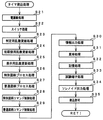
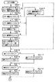
次に、遊技制御処理について説明する。図15は、タイマ割込処理を示すフローチャートである。メイン処理の実行中に、具体的には、ステップS16〜S19のループ処理の実行中における割込許可になっている期間において、タイマ割込が発生すると、遊技制御用マイクロコンピュータ560は、タイマ割込の発生に応じて起動されるタイマ割込処理において遊技制御処理を実行する。タイマ割込処理において、遊技制御用マイクロコンピュータ560は、まず、電源断信号が出力されたか否か(オン状態になったか否か)を検出する電源断処理(電源断検出処理)を実行する(ステップS21)。次いで、スイッチ回路58を介して、ゲートスイッチ32a、始動口スイッチ14a、カウントスイッチ23および入賞口スイッチ29a,30a,33a,39a等のスイッチの検出信号を入力し、それらの状態判定を行なう(スイッチ処理:ステップS22)。具体的には、各スイッチの検出信号を入力する入力ポートの状態がオン状態であれば、各スイッチに対応して設けられているスイッチタイマの値を+1する。
Next, the game control process will be described. FIG. 15 is a flowchart showing the timer interrupt process. When a timer interrupt occurs during execution of the main process, specifically, during a period in which the interrupt is permitted during the execution of the loop process of steps S16 to S19, the
次に、遊技制御に用いられる大当り判定用の乱数等の各判定用乱数を生成するための各カウンタのカウント値を更新する処理を行なう(ステップS23)。遊技制御用マイクロコンピュータ560は、さらに、初期値用乱数および表示用乱数を生成するためのカウンタのカウント値を更新する処理を行なう(ステップS24,S25)。
Next, a process of updating the count value of each counter for generating each determination random number such as a big hit determination random number used for game control is performed (step S23). The
さらに、遊技制御用マイクロコンピュータ560は、特別図柄プロセス処理を行なう(ステップS26)。特別図柄プロセス制御では、遊技状態に応じてパチンコ遊技機1を所定の順序で制御するための特別図柄プロセスフラグに従って該当する処理が選び出されて実行される。そして、特別図柄プロセスフラグの値は、遊技状態に応じて各処理中に更新される。また、普通図柄プロセス処理を行なう(ステップS27)。普通図柄プロセス処理では、普通図柄表示器10の表示状態を所定の順序で制御するための普通図柄プロセスフラグに従って該当する処理が選び出されて実行される。そして、普通図柄プロセスフラグの値は、遊技状態に応じて各処理中に更新される。
Further, the
次いで、遊技制御用マイクロコンピュータ560は、特別図柄の変動に同期する飾り図柄に関する演出制御コマンドをRAM55の所定の領域に設定して演出制御コマンドを送出する処理を行なう(特別図柄コマンド制御処理:ステップS28)。また、普通図柄に関する演出制御コマンドをRAM55の所定の領域に設定して演出制御コマンドを送出する処理を行なう(普通図柄コマンド制御処理:ステップS29)。
Next, the
さらに、遊技制御用マイクロコンピュータ560は、たとえばホール管理用コンピュータに供給される大当り情報、始動情報、確率変動情報などのデータを出力する情報出力処理を行なう(ステップS30)。
Further, the
また、遊技制御用マイクロコンピュータ560は、入賞口スイッチ29a,30a,33a,39a等の検出信号に基づく賞球個数の設定などを行なう賞球処理を実行する(ステップS31)。具体的には、入賞口スイッチ29a,30a,33a,39a等がオンしたことに基づく入賞検出に応じて、払出制御基板37に賞球個数を示す払出個数信号等の払出指令信号を出力する。払出制御基板37に搭載されている払出制御用マイクロコンピュータ370は、賞球個数を示す払出個数信号の受信に応じて球払出装置97を駆動する。
Further, the
そして、遊技制御用マイクロコンピュータ560は、始動入賞記憶数の増減をチェックする記憶処理を実行する(ステップS32)。また、遊技機の制御状態を遊技機外部で確認できるようにするための試験信号を出力する処理である試験端子処理を実行する(ステップS33)。また、この実施の形態では、出力ポートの出力状態に対応したRAM領域(出力ポートバッファ)が設けられているのであるが、遊技制御用マイクロコンピュータ560は、出力ポート3のRAM領域におけるソレノイドに関する内容(図10参照)を出力ポートに出力する(ステップS34:ソレノイド出力処理)。その後、割込許可状態に設定し(ステップS35)、処理を終了する。
Then, the
以上の制御によって、この実施の形態では、遊技制御処理は定期的(たとえば2ms毎)に起動されることになる。なお、この実施の形態では、タイマ割込処理で遊技制御処理が実行されているが、タイマ割込処理ではたとえば割込が発生したことを示すフラグのセットのみがなされ、遊技制御処理はメイン処理において実行されるようにしてもよい。また、ステップS1〜S34の処理が、遊技の進行を制御する遊技制御処理に相当する。 With the above control, in this embodiment, the game control process is started periodically (for example, every 2 ms). In this embodiment, the game control process is executed by the timer interrupt process. However, in the timer interrupt process, for example, only a flag indicating that an interrupt has occurred is set, and the game control process is performed by the main process. May be executed. Moreover, the process of step S1-S34 is corresponded to the game control process which controls progress of a game.
図16および図17は、ステップS20の電源断処理の一例を示すフローチャートである。電源断処理において、遊技制御用マイクロコンピュータ560は、まず、電源断信号が出力されているか否か(オン状態になっているか否か)確認する(ステップS450)。オン状態でなければ、RAM55に形成されているバックアップ監視タイマの値を0クリアする(ステップS451)。オン状態であれば、バックアップ監視タイマの値を1増やす(ステップS452)。そして、バックアップ監視タイマの値が判定値(たとえば2)と一致すれば(ステップS453)、ステップS454以降の電力供給停止時処理すなわち電力の供給停止のための準備処理を実行する。つまり、遊技の進行を制御する状態から遊技状態を保存させるための電力供給停止時処理(電源断時制御処理)を実行する状態に移行する。なお、「RAMに形成されている」とは、RAM内の領域であることを意味する。
16 and 17 are flowcharts illustrating an example of the power-off process in step S20. In the power-off process, the
バックアップ監視タイマと判定値とを用いることによって、判定値に相当する時間だけ電源断信号のオン状態が継続したら、電力供給停止時処理が開始される。すなわち、ノイズ等で一瞬電源断信号のオン状態が発生しても、誤って電力供給停止時処理が開始されるようなことはない。なお、バックアップ監視タイマの値は、遊技機への電力供給が停止しても、所定期間はバックアップ電源によって保存される。従って、メイン処理におけるステップS8では、バックアップ監視タイマの値が判定値と同じ値になっていることによって、電力供給停止時処理の処理結果が保存されていることを確認できる。 By using the backup monitoring timer and the determination value, if the power-off signal is kept on for a time corresponding to the determination value, the power supply stop process is started. That is, even if the power-off signal is turned on for a moment due to noise or the like, the power supply stop process is not erroneously started. Note that the value of the backup monitoring timer is stored by the backup power source for a predetermined period even when power supply to the gaming machine is stopped. Therefore, in step S8 in the main process, it can be confirmed that the processing result of the power supply stop process is stored because the value of the backup monitoring timer is the same as the determination value.
電力供給停止時処理において、遊技制御用マイクロコンピュータ560は、パリティデータを作成する(ステップS454〜S463)。すなわち、まず、クリアデータ(00)をチェックサムデータエリアにセットし(ステップS454)、電力供給停止時でも内容が保存されるべきRAM領域の先頭アドレスに相当するチェックサム算出開始アドレスをポインタにセットする(ステップS455)。また、電力供給停止時でも内容が保存されるべきRAM領域の最終アドレスに相当するチェックサム算出回数をセットする(ステップS456)。
In the power supply stop process, the
次いで、チェックサムデータエリアの内容とポインタが指すRAM領域の内容との排他的論理和を演算する(ステップS457)。演算結果をチェックサムデータエリアにストアするとともに(ステップS458)、ポインタの値を1増やし(ステップS459)、チェックサム算出回数の値を1減算する(ステップS460)。そして、ステップS457〜S460の処理を、チェックサム算出回数の値が0になるまで繰り返す(ステップS461)。 Next, an exclusive OR of the contents of the checksum data area and the contents of the RAM area pointed to by the pointer is calculated (step S457). The calculation result is stored in the checksum data area (step S458), the pointer value is incremented by 1 (step S459), and the checksum calculation count value is decremented by 1 (step S460). Then, the processes in steps S457 to S460 are repeated until the value of the checksum calculation count becomes 0 (step S461).
チェックサム算出回数の値が0になったら、遊技制御用マイクロコンピュータ560は、チェックサムデータエリアの内容の各ビットの値を反転する(ステップS462)。そして、反転後のデータをチェックサムデータエリアにストアする(ステップS463)。このデータが、電源投入時にチェックされるパリティデータとなる。次いで、RAMアクセスレジスタにアクセス禁止値を設定する(ステップS471)。以後、内蔵RAM55のアクセスができなくなる。
When the value of the checksum calculation count becomes 0, the
さらに、遊技制御用マイクロコンピュータ560は、ROM54に格納されているポートクリア設定テーブルの先頭アドレスをポインタにセットする(ステップS472)。ポートクリア設定テーブルにおいて、先頭アドレスには処理数(クリアすべき出力ポートの数)が設定され、次いで、出力ポートのアドレスおよび出力値データ(クリアデータ:出力ポートの各ビットのオフ状態の値)が、処理数分の出力ポートについて順次設定されている。
Further, the
遊技制御用マイクロコンピュータ560は、ポインタが指すアドレスのデータ(すなわち処理数)をロードする(ステップS473)。また、ポインタの値を1増やし(ステップS474)、ポインタが指すアドレスのデータ(すなわち出力ポートのアドレス)をロードする(ステップS475)。さらに、ポインタの値を1増やし(ステップS476)、ポインタが指すアドレスのデータ(すなわち出力値データ)をロードする(ステップS477)。そして、出力値データを出力ポートに出力する(ステップS478)。その後、処理数を1減らし(ステップS479)、処理数が0でなければステップS474に戻る。処理数が0であれば、すなわち、クリアすべき出力ポートを全てクリアしたら、タイマ割込を停止し(ステップS481)、ループ処理に入る。
The
ループ処理では、電源断信号がオフ状態になったか否かを監視する(ステップS482)。電源断信号がオフ状態になった場合には復帰アドレスとして、電源投入時実行アドレス(ステップS1のアドレス)を設定してリターン命令を実行し(ステップS483)、RETI(Return from interrupt)によりタイマ割込処理を終了し、メイン処理に戻る。具体的には、遊技機に設けられている遊技用の装置を制御(自身で制御することと、他のマイクロコンピュータに制御させるために指令信号を送信することの双方を含む概念)する状態に戻る。 In the loop processing, it is monitored whether or not the power-off signal is turned off (step S482). When the power-off signal is turned off, the power-on execution address (the address of step S1) is set as the return address and the return instruction is executed (step S483), and the timer is allocated by RETI (Return from interrupt). The process ends, and the process returns to the main process. Specifically, a state in which a gaming device provided in the gaming machine is controlled (concept including both controlling by itself and transmitting a command signal to cause another microcomputer to control). Return.
また、ループ処理では、リセット確認信号がローレベルのオン状態となったか否かを監視する(ステップS484)。リセット確認信号がオン状態になった場合、すなわち、遊技制御用マイクロコンピュータ560によりリセット確認信号がオン状態となったことが確認された場合に、当該遊技制御用マイクロコンピュータ560がシステムリセット状態となる(システムリセットされる)。すなわち、遊技制御用マイクロコンピュータ560は、始動の状態である動作停止状態に戻される(ステップS485)。本実施の形態におけるリセット信号をオン状態とするための検出電圧の電圧レベルは、前述したように遊技制御用マイクロコンピュータ560の駆動電圧(たとえば4V)よりも高い+4.5Vに設定されている。また、検出電圧の電圧レベルが低下し、リセット信号がオン状態となったときに、後述するステップS936においてリセット確認信号がオン状態となり、遊技制御用マイクロコンピュータ560に入力される。これにより、遊技制御用マイクロコンピュータ560は、駆動電圧よりも高い電圧が未だ供給されているときであっても、積極的に動作停止状態となる。
Further, in the loop processing, it is monitored whether or not the reset confirmation signal is in a low level on state (step S484). When the reset confirmation signal is turned on, that is, when the
以上の処理によって、電力供給が停止する場合には、ステップS454〜S481の電力供給停止時処理が実行され、電力供給停止時処理が実行されたことを示すデータ(バックアップあり指定値およびチェックサム)がバックアップRAMへストアされ、RAMアクセスが禁止状態にされ、出力ポートがクリアされ、かつ、遊技制御処理を実行するためのタイマ割込が禁止状態に設定される。 When the power supply is stopped by the above process, the power supply stop process of steps S454 to S481 is executed, and data indicating that the power supply stop process is executed (specified value with backup and checksum) Is stored in the backup RAM, the RAM access is prohibited, the output port is cleared, and the timer interrupt for executing the game control process is set to the prohibited state.
この実施の形態では、RAM55がバックアップ電源によって電源バックアップ(遊技機への電力供給が停止しても所定期間はRAM55の内容が保存されこと)されている。この例では、ステップS452〜S479の処理によって、バックアップ監視タイマの値とともに、電源断信号が出力されたときのRAM55の内容に基づくチェックサムもRAM55のバックアップ領域に保存される。遊技機への電力供給が停止した後、所定期間内に電力供給が復旧したら、遊技制御手段は、上述したステップS91〜S94の処理によって、RAM55に保存されているデータ(電力供給が停止した直前の遊技制御手段による制御状態である遊技状態を示すデータ(たとえば、プロセスフラグの状態、大当り中フラグの状態、確変フラグの状態、出力ポートの出力状態等)を含む)に従って、遊技状態を、電力供給が停止した直前の状態に戻すことができる。なお、電力供給停止の期間が所定期間を越えたらバックアップ監視タイマの値とチェックサムとが正規の値とは異なるはずであるから、その場合には、ステップS10〜S14の初期化処理が実行される。 In this embodiment, the RAM 55 is backed up by a backup power source (the contents of the RAM 55 are preserved for a predetermined period even when the power supply to the gaming machine is stopped). In this example, the checksum based on the content of the RAM 55 when the power-off signal is output is stored in the backup area of the RAM 55 together with the value of the backup monitoring timer by the processing of steps S452 to S479. After the power supply to the gaming machine is stopped, when the power supply is restored within a predetermined period, the game control means performs data stored in the RAM 55 (immediately before the power supply is stopped) by the processing of steps S91 to S94 described above. In accordance with the data indicating the gaming state which is a control state by the gaming control means (for example, including the process flag state, the big hit flag state, the probability variation flag state, the output port output state, etc.) It is possible to return to the state immediately before the supply is stopped. If the power supply stop period exceeds the predetermined period, the value of the backup monitoring timer and the checksum should be different from the regular values. In this case, the initialization process of steps S10 to S14 is executed. The
以上のように、電力供給停止時処理(電力の供給停止のための準備処理)によって、遊技状態を電力供給が停止した直前の状態に戻すためのデータが確実に遊技制御用記憶手段(この例ではRAM55の一部の領域)に保存される。よって、停電等による電源断が生じても、所定期間内に電源が復旧すれば、遊技状態を電力供給が停止した直前の状態に戻すことができる。 As described above, the process for storing the game control reliably (in this example) the data for returning the game state to the state immediately before the power supply is stopped by the power supply stop process (preparation process for power supply stop). Then, it is stored in a part of the RAM 55). Therefore, even if the power is cut off due to a power failure or the like, if the power is restored within a predetermined period, the gaming state can be returned to the state immediately before the power supply is stopped.
また、電源断信号がオフ状態になった場合には、ステップS1に戻る。その場合、電力供給停止時処理が実行されたことを示すデータが設定されているので、ステップS91〜S94の遊技状態復旧処理が実行される。よって、電力供給停止時処理を実行した後に払出制御基板37からの電源断信号がオフ状態になったときには、遊技の進行を制御する状態に戻る。従って、電源瞬断等が生じても、遊技制御処理が停止してしまうようなことはなく、自動的に、遊技制御処理が続行される。
If the power-off signal is turned off, the process returns to step S1. In this case, since data indicating that the power supply stop process has been executed is set, the game state recovery process of steps S91 to S94 is executed. Therefore, when the power-off signal from the
なお、払出制御基板37に対して送信される接続確認信号は、出力ポートをクリアする処理によってオフ状態に設定される。また、ステップS92およびS12の作業領域の設定では、接続確認信号に対応した出力ポートバッファの内容が、接続確認信号のオン状態に対応した値に設定される。そして、ステップS31の賞球処理が実行されると、出力ポートバッファの内容が出力ポートに出力されるので、払出制御基板37への接続確認信号がオン状態になる。従って、接続確認信号は、主基板31の立ち上がり時に出力される(オン状態になる)ことになる。なお、電源瞬断等から復帰した場合も、接続確認信号が出力される。
The connection confirmation signal transmitted to the
次に、メイン処理におけるスイッチ処理(ステップS21)を説明する。この実施の形態では、入賞検出またはゲート通過に関わる各スイッチの検出信号のオン状態が所定時間継続すると、確かにスイッチがオンしたと判定されスイッチオンに対応した処理が開始される。図18は、スイッチ処理で使用されるRAM55に形成される各1バイトのバッファを示す説明図である。前回ポートバッファは、前回(たとえば2ms前)のスイッチオン/オフの判定結果が格納されるバッファである。ポートバッファは、今回入力したポート0の内容が格納されるバッファである。スイッチオンバッファは、スイッチのオンが検出された場合に対応ビットが1に設定され、スイッチのオフが検出された場合に対応ビットが0に設定されるバッファである。
Next, the switch process (step S21) in the main process will be described. In this embodiment, when the ON state of the detection signal of each switch related to winning detection or gate passage continues for a predetermined time, it is determined that the switch is surely turned on, and processing corresponding to the switch on is started. FIG. 18 is an explanatory diagram showing each 1-byte buffer formed in the RAM 55 used in the switching process. The previous port buffer is a buffer that stores the previous switch-on / off determination result (for example, 2 ms before). The port buffer is a buffer in which the contents of
図19は、遊技制御処理におけるステップS21のスイッチ処理の処理例を示すフローチャートである。スイッチ処理において、遊技制御用マイクロコンピュータ560は、まず、入力ポート0(図12参照)に入力されているデータを入力し(ステップS101)、入力したデータをポートバッファにセットする(ステップS102)。次いで、RAM55に形成されるウェイトカウンタの初期値をセットし(ステップS103)、ウェイトカウンタの値が0になるまで、ウェイトカウンタの値を1ずつ減算する(ステップS104,S105)。
FIG. 19 is a flowchart illustrating a processing example of the switch processing in step S21 in the game control processing. In the switch process, the
ウェイトカウンタの値が0になると、再度、入力ポート0のデータを入力し(ステップS106)、入力したデータとポートバッファにセットされているデータとの間で、ビット毎に論理積をとる(ステップS107)。そして、論理積の演算結果を、ポートバッファにセットする(ステップS108)。ステップS103〜S108の処理によって、ほぼ[ウェイトカウンタの初期値×(ステップS104,S105の処理時間)]の時間間隔を置いて入力ポート0から入力した2回の入力データのうち、2回とも「1」になっているビットのみが、ポートバッファにおいて「1」になる。つまり、所定期間としての[ウェイトカウンタの初期値×(ステップS104,S105の処理時間)]だけスイッチの検出信号のオン状態が継続すると、ポートバッファにおける対応するビットが「1」になる。
When the value of the wait counter reaches 0, the data of the
さらに、遊技制御用マイクロコンピュータ560は、前回ポートバッファにセットされているデータとポートバッファにセットされているデータとの間で、ビット毎に排他的論理和をとる(ステップS109)。排他的論理和の演算結果において、前回(たとえば2ms前)のスイッチオン/オフの判定結果と、今回オンと判定されたスイッチオン/オフの判定結果とが異なっているスイッチに対応したビットが「1」になる。遊技制御用マイクロコンピュータ560は、さらに、排他的論理和の演算結果と、ポートバッファにセットされているデータとの間で、ビット毎に論理積をとる(ステップS110)。この結果、前回のスイッチオン/オフの判定結果と今回オンと判定されたスイッチオン/オフの判定結果とが異なっているスイッチに対応したビット(排他的論理和演算結果による)のうち、今回オンと判定されたスイッチに対応したビット(論理積演算による)のみが「1」として残る。
Further, the
そして、遊技制御用マイクロコンピュータ560は、ステップS110における論理積の演算結果をスイッチオンバッファにセットし(ステップS111)、ステップS108における演算結果がセットされているポートバッファの内容を前回ポートバッファにセットする(ステップS112)。
Then, the
以上の処理によって、所定期間継続してオン状態であったスイッチのうち、前回(たとえば2ms前)のスイッチオン/オフの判定結果がオフであったスイッチ、すなわち、オフ状態からオン状態に変化したスイッチに対応したビットが、スイッチオンバッファにおいて「1」になっている。 Through the above processing, among the switches that have been on for a predetermined period of time, the switch that has been turned off last time (for example, 2 ms before), that is, the switch that has been turned off, that is, changed from the off state to the on state The bit corresponding to the switch is “1” in the switch-on buffer.
次に、主基板31と払出制御基板37との間で送受信される払出制御信号について説明する。図20は、遊技制御手段から払出制御手段に対して出力される制御信号の内容の一例を示す説明図である。この実施の形態では、払出制御等に関する各種の制御を行なうために、主基板31と払出制御基板37との間で複数種類の制御信号が送受信される。図20に示すように、接続確認信号は、主基板31の立ち上がり時(遊技制御手段が遊技制御処理を開始したとき)に出力され、払出制御基板37に対して主基板31が立ち上がったことを通知するための信号(主基板31の接続確認信号)である。また、接続確認信号は、賞球払出が可能な状態であることを示す。
Next, payout control signals transmitted and received between the
賞球REQ信号は、賞球の払出要求時に出力状態(=オン状態)になる信号(すなわち賞球払出要求のトリガ信号)である。また、賞球REQ信号は、所定期間が経過すると、停止状態(オフ状態)になる。賞球個数信号は、払出要求を行なう遊技球の個数(0〜15個)を指定するために出力される信号(賞球個数コマンド)である。 The prize ball REQ signal is a signal that is in an output state (= ON state) when a prize ball payout request is made (that is, a trigger signal for a prize ball payout request). In addition, the prize ball REQ signal is in a stopped state (off state) when a predetermined period has elapsed. The award ball number signal is a signal (award ball number command) output for designating the number of game balls (0 to 15) for which a payout request is made.
リセット確認信号は、払出制御手段が、電源監視回路920からのリセット信号がオフ状態からオン状態となったことに基づいて、オフ状態からオン状態として遊技制御手段の遊技制御動作の停止を指示するための信号である。また、リセット確認信号は、払出制御手段が、電源監視回路920からのリセット信号がオン状態からオフ状態となったことに基づいて、オン状態からオフ状態として遊技制御手段の遊技制御動作の開始を指示するための信号である。すなわち、制御動作の停止/開始指示を主基板31に通知するための信号として用いられる。
The reset confirmation signal instructs the payout control means to stop the game control operation of the game control means from the off state to the on state based on the fact that the reset signal from the power
図21は、図20に示す各制御信号の送受信に用いられる信号線等を示すブロック図である。図21に示すように、接続確認信号、賞球REQ信号および賞球個数信号は、遊技制御用マイクロコンピュータ560によって出力回路67を介して出力され、入力回路373Aを介して払出制御用マイクロコンピュータ370に入力される。また、電源断信号は、払出制御基板37に搭載された出力回路373Bを介して出力され、入力回路68を介して遊技制御用マイクロコンピュータ560に入力される。また、リセット確認信号は、払出制御用マイクロコンピュータ370によって出力回路373Bを介して出力され、入力回路68を介して遊技制御用マイクロコンピュータ560に入力される。接続確認信号、賞球REQ信号、電源断信号、およびリセット確認信号は、それぞれ1ビットのデータであり、1本の信号線によって送信される。賞球個数信号は、0個〜15個を指定するので、4ビットのデータで構成され4本の信号線によって送信される。
FIG. 21 is a block diagram showing signal lines and the like used for transmission / reception of each control signal shown in FIG. As shown in FIG. 21, the connection confirmation signal, the prize ball REQ signal, and the prize ball number signal are output by the
図22は、払出制御信号の出力の仕方の一例を示すタイミング図である。図22に示すように、入賞検出スイッチが遊技球の入賞を検出すると、遊技制御手段は、賞球REQ信号をオン状態にするとともに、賞球個数信号の出力状態を、入賞に応じて払出される賞球数に応じた状態にする。なお、具体的には、遊技制御用マイクロコンピュータ560は、遊技球が遊技機に設けられている入賞領域に入賞したことが入賞検出スイッチの検出信号によって検知すると、あらかじめ決められた賞球数をバックアップRAMに形成されている総賞球数格納バッファの内容に加算する。そして、総賞球数格納バッファの内容が0でない値になったら、賞球REQ信号をオン状態にするとともに、賞球個数信号の出力状態を、入賞に応じて払出される賞球数に応じた状態にする。
FIG. 22 is a timing chart showing an example of how to output the payout control signal. As shown in FIG. 22, when the winning detection switch detects the winning of the game ball, the game control means turns on the winning ball REQ signal and pays out the output state of the winning ball number signal according to the winning. Set the state according to the number of winning balls. Specifically, when the
また、この実施の形態では、始動口スイッチ14aで遊技球が検出されると4個の賞球払出を行ない、入賞口スイッチ33a,39a,29a,30aのいずれかで遊技球が検出されると7個の賞球払出を行ない、Vカウントスイッチ22またはカウントスイッチ23で遊技球が検出されると15個の賞球払出を行なう。また、上述したように、賞球個数信号は4ビットで構成されているので、8ビットで表現されている00(H)〜0F(H)の賞球個数コマンドのうち、下位の4ビットが賞球個数信号によって主基板31から払出制御基板37に伝達される。以下、「00(H)〜0F(H)の賞球個数信号」のように表現することがあるが、実際には、賞球個数信号は、8ビットで表現されている00(H)〜0F(H)のうちの下位の4ビットに相当する。
Further, in this embodiment, when a game ball is detected by the start port switch 14a, four prize balls are paid out, and when a game ball is detected by any of the
払出制御手段は、賞球REQ信号の受信を確認すると、賞球個数信号の受信状態を確認し、賞球個数信号が示す賞球数を賞球未払出個数カウンタに加算する。 When the payout control means confirms the reception of the prize ball REQ signal, the payout control means confirms the reception state of the prize ball number signal, and adds the prize ball number indicated by the prize ball number signal to the prize ball unpaid number counter.
遊技制御手段は、所定の賞球REQ信号出力時間の経過後に、賞球REQ信号をオフ状態にするとともに、賞球個数信号の出力状態をクリアしてオフ状態にする。すなわち、賞球個数信号が0個を示す状態(無効コマンドを出力する状態)にする。従って、賞球個数信号は、賞球REQ信号がオン状態であるときには無効コマンド出力状態になっているので、払出制御手段において、ノイズ等によって賞球REQ信号のオン状態が検出されたような場合でも、誤って賞球払出を実行してしまうようなことはない。なお、賞球REQ信号出力時間は、払出制御基板37側で賞球REQ信号の受信を確実に認識できる時間としてあらかじめ定められた賞球REQ信号のオン状態を継続する時間である。
The game control means turns off the prize ball REQ signal after a predetermined prize ball REQ signal output time elapses and clears the output state of the prize ball number signal to turn it off. That is, a state in which the prize ball number signal indicates 0 (a state in which an invalid command is output) is set. Accordingly, since the prize ball number signal is in an invalid command output state when the prize ball REQ signal is in an on state, the on-state of the prize ball REQ signal is detected by noise or the like in the payout control means. However, there is no such thing as accidentally paying out a prize ball. The prize ball REQ signal output time is a period of time during which the prize ball REQ signal is turned on, which is predetermined as a time during which the
図23は、ステップS31の賞球処理の一例を示すフローチャートである。賞球処理において、遊技制御用マイクロコンピュータ560は、賞球個数加算処理(ステップS201)と賞球制御処理(ステップS202)とを実行する。そして、RAM55に形成されるポート0バッファの内容をポート0に出力する(ステップS203)。なお、ポート0バッファの内容は、賞球制御処理において更新される。
FIG. 23 is a flowchart showing an example of the prize ball processing in step S31. In the prize ball process, the
賞球個数加算処理では、図24に示す賞球個数テーブルが使用される。賞球個数テーブルは、ROM54に設定されている。賞球個数テーブルの先頭アドレスには処理数(この例では「7」)が設定され、その後に、スイッチオンバッファの下位アドレス、入賞により賞球を払出すことになる入賞口の各スイッチについてのスイッチ入力ビット判定値、賞球数が、入賞口の各スイッチのそれぞれに対応して順次設定されている。なお、スイッチ入力ビット判定値は、入力ポート0における各スイッチの検出信号が入力されるビットに対応した値である(図12参照)。また、スイッチオンバッファの上位アドレスは固定的な値(たとえば7F(H))である。また、賞球個数テーブルにおいて、7つのスイッチオンバッファの下位アドレスのそれぞれには、同じデータが設定されている。
In the prize ball number adding process, a prize ball number table shown in FIG. 24 is used. The prize ball number table is set in the ROM 54. The number of processes (in this example, “7”) is set in the head address of the winning ball number table, and thereafter, the lower address of the switch-on buffer, and each switch of the winning opening that will pay out the winning ball by winning. The switch input bit determination value and the number of winning balls are sequentially set corresponding to each switch of the winning opening. The switch input bit determination value is a value corresponding to the bit to which the detection signal of each switch at the
図25は、賞球個数加算処理を示すフローチャートである。賞球個数加算処理において、遊技制御用マイクロコンピュータ560は、賞球個数テーブルの先頭アドレスをポインタにセットする(ステップS211)。そして、ポインタが指すアドレスのデータ(この場合には処理数)をロードする(ステップS212)。次に、スイッチオンバッファの上位アドレス(8ビット)を2バイトのチェックポインタの上位1バイトにセットする(ステップS213)。
FIG. 25 is a flowchart showing the prize ball number adding process. In the winning ball number adding process, the
そして、ポインタの値を1増やし(ステップS214)、ポインタが指す賞球個数テーブルのデータ(この場合にはスイッチオンバッファの下位アドレス)をチェックポインタの下位1バイトにセットした後(ステップS215)、ポインタの値を1増やす(ステップS216)。次いで、チェックポインタが指すアドレスのデータ、すなわちスイッチオンバッファの内容をレジスタにロードし(ステップS217)、ロードした内容と、ポインタが指す賞球個数テーブルのデータ(この場合にはスイッチ入力ビット判定値)との論理積をとる(ステップS218)。この結果、スイッチオンバッファの内容がロードされたレジスタには、検査対象としているスイッチの検出信号に対応したビット以外の7ビットが0になる。そして、ポインタの値を1増やす(ステップS219)。 Then, the pointer value is incremented by 1 (step S214), and the data of the prize ball number table pointed to by the pointer (in this case, the lower address of the switch-on buffer) is set in the lower 1 byte of the check pointer (step S215). The pointer value is increased by 1 (step S216). Next, the address data pointed to by the check pointer, that is, the contents of the switch-on buffer is loaded into the register (step S217), and the loaded contents and the data of the prize ball number table pointed to by the pointer (in this case, the switch input bit judgment value) ) And the logical product (step S218). As a result, 7 bits other than the bit corresponding to the detection signal of the switch to be inspected become 0 in the register loaded with the contents of the switch-on buffer. Then, the pointer value is incremented by 1 (step S219).
ステップS218における演算結果が0でなれば、すなわち、検査対象のスイッチの検出信号がオン状態であれば、ポインタが指す賞球個数テーブルのデータ(この場合には賞球個数)を賞球加算値に設定し(ステップS220,S221)、賞球加算値を、RAM55に形成されている16ビットの総賞球数格納バッファの内容に加算する(ステップS222)。加算の結果、桁上げが発生した場合には、総賞球数格納バッファの内容を65535(=FFFF(H))に設定する(ステップS223,224)。 If the calculation result in step S218 is 0, that is, if the detection signal of the switch to be inspected is on, the prize ball number table data pointed to by the pointer (in this case, the prize ball number) is used as the prize ball addition value. (Steps S220 and S221), and the prize ball addition value is added to the contents of the 16-bit total prize ball number storage buffer formed in the RAM 55 (step S222). If a carry occurs as a result of the addition, the content of the total number of winning balls storage buffer is set to 65535 (= FFFF (H)) (steps S223 and 224).
ステップS225では処理数を1減らし、処理数が0であれば処理を終了し、処理数が0でなければステップS214に戻る(ステップS226)。また、ステップS220において、ステップS218における演算結果が0であること、すなわち、検査対象のスイッチの検出信号がオフ状態であることを確認したら、ステップS225に移行する。 In step S225, the number of processes is reduced by 1. If the number of processes is 0, the process ends. If the number of processes is not 0, the process returns to step S214 (step S226). In step S220, when it is confirmed that the calculation result in step S218 is 0, that is, the detection signal of the switch to be inspected is in the OFF state, the process proceeds to step S225.
図26は、ステップS201の賞球制御処理を示すフローチャートである。賞球制御処理では、遊技制御用マイクロコンピュータ560は、賞球プロセスコードの値に応じて、ステップS231〜S233のいずれかの処理を実行する。
FIG. 26 is a flowchart showing the prize ball control process in step S201. In the prize ball control process, the
図27は、賞球プロセスコードの値が0の場合に実行される賞球待ち処理1(ステップS231)を示すフローチャートである。遊技制御用マイクロコンピュータ560は、賞球待ち処理1において、賞球待機中出力値(10(H))をポート0バッファにセットする(ステップS241)。なお、賞球待機中出力値がポート0バッファにセットされると、ステップS203においてポート0バッファの内容がポート0に出力されることによって、賞球REQ信号がオフ状態になり、接続確認信号のオン状態が維持される(図10参照)。また、賞球個数信号が無効コマンド(00(H))を出力する状態になる。
FIG. 27 is a flowchart showing the prize waiting process 1 (step S231) executed when the value of the prize ball process code is zero. In the award
次いで、遊技制御用マイクロコンピュータ560は、賞球タイマが0であるか否か確認する(ステップS242)。賞球タイマが0でなければ、賞球タイマの値を1減らして(ステップS243)、処理を終了する。賞球タイマは賞球処理において必要となる時間を計測するためのタイマであるが、この段階で賞球タイマの値が0でないということは、前回の払出処理が完了した後、次に賞球REQ信号をオン状態にするまでの待ち時間(連続して賞球払出が実行される場合に複数の賞球REQ信号のオン期間の間に間隔を設けるための時間)が終了していないことを意味する。なお、賞球タイマは、後述する賞球待ち処理2のステップS263でセットされる。また、ステップS241〜S243の処理は、ステップS233の賞球待ち処理2の実行が完了して前回の賞球制御処理が完了した後に、賞球REQ信号をオフ状態にするとともに、賞球個数信号として無効コマンド(00(H))を出力するための処理である。
Next, the
賞球タイマの値が0であれば、次いで、遊技制御用マイクロコンピュータ560は、総賞球数格納バッファの内容を確認する(ステップS244)。その値が0であれば処理を終了し、0でなければ、賞球プロセスコードの値を1にした後(ステップS245)、処理を終了する。
If the value of the prize ball timer is 0, the
図28は、賞球プロセスコードの値が1の場合に実行される賞球送信処理(ステップS232)を示すフローチャートである。遊技制御用マイクロコンピュータ560は、賞球送信処理において、総賞球数格納バッファの内容が賞球コマンド最大値(この例では「15」)よりも小さいか否か確認する(ステップS251)。総賞球数格納バッファの内容が賞球コマンド最大値以上であれば、賞球コマンド最大値を賞球個数バッファに設定する(ステップS252)。また、総賞球数格納バッファの内容が賞球コマンド最大値よりも小さい場合には、総賞球数格納バッファの内容を賞球個数バッファに設定する(ステップS253)。
FIG. 28 is a flowchart showing a prize ball transmission process (step S232) executed when the value of the prize ball process code is 1. In the prize ball transmission process, the
その後、賞球REQ中出力値(30(H))を出力ポート0バッファにセットする(ステップS254)。なお、賞球REQ中出力値が出力ポート0バッファにセットされると、ステップS203において出力ポート0バッファの内容がポート0に出力されることによって、賞球REQ信号がオン状態になり、接続確認信号のオン状態が維持される(図10参照)。また、賞球個数バッファの内容を出力ポート0バッファの下位4ビットにセットする(ステップS255)。
Thereafter, the output value (30 (H)) during the prize ball REQ is set in the
この実施の形態では、賞球コマンド最大値は「15」である。従って、最大で「15」の払出数を指定する賞球制御信号が払出制御基板37に送信される。賞球制御信号を送信すると、遊技制御用マイクロコンピュータ560は、総賞球数格納バッファの内容から、賞球個数バッファの内容(払出制御手段に指令した賞球払出個数)を減算する(ステップS256)。また、遊技制御用マイクロコンピュータ560は、賞球タイマにREQ終了判定時間値(たとえば3)をセットする(ステップS257)。REQ終了判定時間値は、賞球REQ信号オフ待ち時間を作成するための値である。そして、賞球プロセスコードの値を2にして(ステップS258)、処理を終了する。
In this embodiment, the maximum value of the prize ball command is “15”. Accordingly, a prize ball control signal designating the maximum number of payouts of “15” is transmitted to the
なお、この例では、賞球制御信号を送信したあとにステップS256の減算処理を行なうが、具体的には、ステップS254およびステップS255で賞球REQ中出力値と賞球個数バッファの内容とが出力ポート0バッファにセットされたあと、ステップS203にて出力ポート0バッファの内容がポート0に出力される前に行なわれる。ただし、ステップS254およびステップS255で賞球REQ中出力値と賞球個数バッファの内容とが出力ポート0バッファにセットされ、その後にステップS203において出力ポート0バッファの内容がポート0に出力されて、賞球REQ信号が実際にオン状態となったあとに、総賞球数格納バッファの内容から賞球個数バッファの内容を減算する減算処理を行なうようにしてもよい。
In this example, after the prize ball control signal is transmitted, the subtraction process in step S256 is performed. Specifically, in step S254 and step S255, the output value in the prize ball REQ and the content of the prize ball number buffer are obtained. After the
図29は、賞球プロセスコードの値が2の場合に実行される賞球待ち処理2(ステップS233)を示すフローチャートである。遊技制御用マイクロコンピュータ560は、賞球待ち処理2において、賞球タイマの値を確認し(ステップS261)、その値が0でなければ賞球タイマの値を1減らして(ステップS262)、処理を終了する。賞球タイマの値が0になったら、すなわち図23に示す賞球REQ信号オフ待ち時間が経過したら、賞球REQ待ち時間を賞球タイマにセットする(ステップS263)。そして、賞球プロセスコードの値を0にして(ステップS264)、処理を終了する。上述したように、賞球REQ待ち時間は、次に賞球REQ信号をオン状態にするまでの待ち時間(連続して賞球払出が実行される場合に、複数の賞球REQ信号のオン期間の間に間隔を設けるための時間)である。
FIG. 29 is a flowchart showing the winning ball waiting process 2 (step S233) executed when the value of the winning ball process code is 2. In the award
以上の処理によって、遊技制御手段は、払出条件の成立に基づいて払出される賞球としての遊技球の総数を特定可能に総賞球数格納バッファに記憶する。また、遊技制御手段は、総賞球数格納バッファに記憶されている賞球数に基づいて払出制御手段に対して所定数の賞球の払出数を指定する払出指令信号を送信する。ここで、所定数は、総賞球数格納バッファに記憶されている賞球数が15個以上であれば15であり、15個未満であれば、総賞球数格納バッファに記憶されている賞球数である。そして、賞球払出を指定する賞球制御信号の送信を開始したときに、総賞球数格納バッファに記憶されている賞球数から払出指令信号で指定した払出数を減算する減算処理を行なう。 Through the above processing, the game control means stores the total number of game balls as prize balls to be paid out based on the establishment of the payout condition in the total prize ball number storage buffer so as to be specified. Further, the game control means transmits a payout command signal for designating a payout number of a predetermined number of prize balls to the payout control means based on the number of prize balls stored in the total prize ball number storage buffer. Here, the predetermined number is 15 if the number of prize balls stored in the total prize ball number storage buffer is 15 or more, and is stored in the total prize ball number storage buffer if it is less than 15. The number of prize balls. Then, when transmission of a prize ball control signal designating a prize ball payout is started, a subtraction process is performed for subtracting the number of prizes designated by the payout command signal from the number of prize balls stored in the total prize ball number storage buffer. .
なお、この実施の形態では、払出条件の成立に基づいて払出される景品遊技媒体の総数を特定可能に記憶する景品遊技媒体数記憶手段として、総数そのものを記憶する総賞球数格納バッファが例示されたが、景品遊技媒体の総数を特定可能に記憶する景品遊技媒体数記憶手段は、各入賞領域への入賞数を記憶するものや、賞球数が同じである入賞領域毎の入賞数(たとえば6個の賞球数に対応した入賞口14、10個の賞球数に対応した入賞口33,39,29,30、15個の賞球数に対応した大入賞口への入賞数であって、未だ賞球払出が終了していない入賞数)を記憶するものであってもよい。
In this embodiment, as the prize game medium number storage means for storing the total number of prize game media to be paid out based on the establishment of the payout condition, a total prize ball number storage buffer for storing the total number itself is exemplified. However, the prize game medium number storage means for storing the total number of prize game media so as to be identifiable is one that stores the number of prizes received in each prize area, or the number of prizes for each prize area (the same number of prize balls) ( For example, the winning
次に、払出制御手段(払出制御用マイクロコンピュータ370およびI/Oポート)の動作を説明する。図30は、払出制御手段における出力ポートの割り当ての例を示す説明図である。図30に示すように、出力ポート0は、ステッピングモータによる発射モータ94に供給される各相の信号と、ステッピングモータによる払出モータ289に供給される各相の信号とを出力するための出力ポートである。また、出力ポート1は、球切れLED52、および賞球LED51と、遊技機外部に出力される賞球中信号、賞球情報、球貸し情報および遊技機エラー状態信号、およびリセット確認信号を出力するための出力ポートである。出力ポート2は、7セグメントLEDによるエラー表示LED374の各セグメント出力の出力ポートである。
Next, the operation of the payout control means (the
なお、払出制御基板37には、図30には示されていないが、カードユニット50へのEXS信号およびPRDY信号を出力するための出力ポート3も設けられている。
Although not shown in FIG. 30, the
図31は、払出制御手段における入力ポートのビット割り当ての例を示す説明図である。図31に示すように、入力ポート0のビット0〜3には、4ビットの賞球個数信号が入力され、ビット4〜7には、それぞれ、主基板31からの接続確認信号、主基板31からの賞球REQ信号、球切れスイッチ187の検出信号、払出モータ位置センサ295の検出信号が入力される。また、入力ポート1のビット0〜3には、それぞれ、タッチセンサからのタッチセンサ信号(発射制御信号)、払出個数カウントスイッチ301の検出信号、エラー解除スイッチ375からの操作信号、満タンスイッチ48の検出信号が入力される。入力ポート1のビット4〜6には、それぞれ、カードユニット50からのVL信号、BRDY信号、BRQ信号が入力される。入力ポート2には、電源基板910からのクリアスイッチ921の出力信号(クリア信号:図31では「クリアスイッチ」として示す。)、および電源断信号が入力される。
FIG. 31 is an explanatory diagram showing an example of bit assignment of input ports in the payout control means. As shown in FIG. 31, a 4-bit prize ball number signal is input to
次に、払出制御手段の動作について説明する。図32は、払出制御手段が実行するメイン処理を示すフローチャートである。遊技機に対する電力供給が開始され、リセット信号がハイレベルになると、払出制御用マイクロコンピュータ370は、メイン処理を開始する。メイン処理では、払出制御用マイクロコンピュータ370は、まず、必要な初期設定を行なう。すなわち、払出制御用マイクロコンピュータ370は、まず、割込禁止に設定する(ステップS701)。次に、割込モードを割込モード2に設定し(ステップS702)、スタックポインタにスタックポインタ指定アドレスを設定する(ステップS703)。また、払出制御用マイクロコンピュータ370は、内蔵デバイスレジスタの初期化を行ない(ステップS704)、CTCおよびPIOの初期化(ステップS705)を行なった後に、RAMをアクセス可能状態に設定する(ステップS706)。また、賞球未払出個数カウンタ初期値として0000(H)をセットする(ステップS707)。
Next, the operation of the payout control means will be described. FIG. 32 is a flowchart showing main processing executed by the payout control means. When power supply to the gaming machine is started and the reset signal becomes high level, the
この実施の形態では、内蔵CTCのうちの一つのチャネルがタイマモードで使用される。従って、ステップS704の内蔵デバイスレジスタの設定処理およびステップS705の処理において、使用するチャネルをタイマモードに設定するためのレジスタ設定、割込発生を許可するためのレジスタ設定および割込ベクタを設定するためのレジスタ設定が行なわれる。そして、そのチャネルによる割込がタイマ割込として用いられる。タイマ割込をたとえば2ms毎に発生させたい場合は、初期値として2msに相当する値が所定のレジスタ(時間定数レジスタ)に設定される。 In this embodiment, one channel of the built-in CTC is used in the timer mode. Accordingly, in the built-in device register setting process in step S704 and the process in step S705, register setting for setting the channel to be used to timer mode, register setting for permitting interrupt generation, and setting an interrupt vector. The register is set. The interrupt by the channel is used as a timer interrupt. For example, when it is desired to generate a timer interrupt every 2 ms, a value corresponding to 2 ms is set in a predetermined register (time constant register) as an initial value.
なお、タイマモードに設定されたチャネル(この実施の形態ではチャネル3)に設定される割込ベクタは、タイマ割込処理の先頭アドレスに相当するものである。具体的は、Iレジスタに設定された値と割込ベクタとでタイマ割込処理の先頭アドレスが特定される。タイマ割込処理では、払出手段を制御する払出制御処理(少なくとも主基板からの賞球払出に関する指令信号に応じて球払出装置97を駆動する処理を含み、球貸し要求に応じて球払出装置97を駆動する処理が含まれていてもよい。)が実行される。
The interrupt vector set for the channel set to the timer mode (
この実施の形態では、払出制御用マイクロコンピュータ370でも割込モード2が設定される。従って、内蔵CTCのカウントアップに基づく割込処理を使用することができる。また、CTCが送出した割込ベクタに応じた割込処理開始アドレスを設定することができる。CTCのチャネル3(CH3)のカウントアップに基づく割込は、CPUの内部クロック(システムクロック)をカウントダウンしてレジスタ値が「0」になったら発生する割込であり、タイマ割込として用いられる。
In this embodiment, the
次いで、入力ポート2を介して入力されるクリアスイッチ921の出力信号の状態を1回だけ確認する(ステップS708)。その確認においてオンを検出した場合には、払出制御用マイクロコンピュータ370は、初期化処理を実行する(ステップS712〜ステップS715)。クリアスイッチ921がオンの状態でない場合には、遊技機への電力供給が停止したときにバックアップRAM領域のデータ保護処理(たとえばパリティデータの付加等の電力供給停止時処理)が行なわれたか否か確認する(ステップS709)。保護処理が行なわれていたか否かは、後述する電力供給停止時処理においてバックアップRAM領域に保存されるバックアップ監視タイマの値が、バックアップRAM領域のデータ保護処理を実行したことに応じた値(たとえば2)になっているか否かによって確認される。なお、そのような確認の仕方は一例であって、たとえば、電力供給停止時処理においてバックアップフラグ領域にデータ保護処理を実行したことを示すフラグをセットし、ステップS709において、そのフラグがセットされていることを確認したらバックアップありと判定してもよい。
Next, the state of the output signal of the
バックアップありと判定したら、払出制御用マイクロコンピュータ370は、バックアップRAM領域のデータチェック(この例ではパリティチェック)を行なう(ステップS710)。この実施の形態では、クリアデータ(00)をチェックサムデータエリアにセットし、チェックサム算出開始アドレスをポインタにセットする。また、チェックサムの対象となるデータ数に対応するチェックサム算出回数をセットする。そして、チェックサムデータエリアの内容とポインタが指すRAM領域の内容との排他的論理和を演算する。演算結果をチェックサムデータエリアにストアするとともに、ポインタの値を1増やし、チェックサム算出回数の値を1減算する。以上の処理が、チェックサム算出回数の値が0になるまで繰り返される。チェックサム算出回数の値が0になったら、遊技制御用マイクロコンピュータ560は、チェックサムデータエリアの内容の各ビットの値を反転し、反転後のデータをチェックサムとする。
If it is determined that there is a backup, the
後述する電力供給停止時処理において、上記の処理と同様の処理(図34に示す処理)によってチェックサムが算出され、チェックサムはバックアップRAM領域に保存されている。ステップS710では、算出したチェックサムと保存されているチェックサムとを比較する。不測の停電等の電力供給停止が生じた後に復旧した場合には、バックアップRAM領域のデータは保存されているはずであるから、チェック結果(比較結果)は正常(一致)になる。チェック結果が正常でないということは、バックアップRAM領域のデータが、電力供給停止時のデータとは異なっていることを意味する。そのような場合には、内部状態を電力供給停止時の状態に戻すことができないので、払出制御側復旧処理を実行せず、初期化処理(ステップS712〜S715の処理)を実行する。 In the power supply stop process described later, the checksum is calculated by the same process (the process shown in FIG. 34) as the above process, and the checksum is stored in the backup RAM area. In step S710, the calculated checksum is compared with the stored checksum. When the power supply is stopped after an unexpected power outage or the like, the data in the backup RAM area should be saved, so the check result (comparison result) is normal (matched). That the check result is not normal means that the data in the backup RAM area is different from the data when the power supply is stopped. In such a case, since the internal state cannot be returned to the state at the time of power supply stop, the payout control side recovery process is not executed, and the initialization process (steps S712 to S715) is executed.
チェック結果が正常であれば、払出制御用マイクロコンピュータ370は、払出制御側復旧処理を行なう。具体的には、賞球未払出個数カウンタ初期値として、バックアップRAMに形成されている賞球未払出個数カウンタの値をセットする(ステップS711)。そして、ステップS713以降の処理を実行する。
If the check result is normal, the
初期化処理では、払出制御用マイクロコンピュータ370は、まず、RAMクリア処理を行なう(ステップS712)。また、RAM領域のフラグやカウンタなどに初期値を設定する(ステップS713)。ステップS713の処理には、賞球未払出個数カウンタ初期値を賞球未払出個数カウンタにセットする処理が含まれる。従って、払出制御側復旧処理(ステップS711)が実行された場合には、バックアップRAMに保存されていた賞球未払出個数カウンタの値が、あらためて賞球未払出個数カウンタにセットされる。換言すれば、バックアップRAMに保存されていた賞球未払出個数カウンタの値がそのまま使用される。
In the initialization process, the
そして、定期的にタイマ割込がかかるように払出制御用マイクロコンピュータ370に設けられているCTCのレジスタの設定を行なう(ステップS714)。すなわち、初期値としてタイマ割込発生間隔に相当する値が所定のレジスタ(時間定数レジスタ)に設定される。そして、初期設定処理のステップS701において割込禁止とされているので、初期化処理を終える前に割込が許可される(ステップS715)。
Then, the CTC register provided in the
さらに、初期化処理を終了すると、払出制御用マイクロコンピュータ370は、リセット確認信号をオン状態からオフ状態に切り替え、主基板31に遊技制御動作の開始指示を行なう(ステップS716)。その後、タイマ割込の発生を監視するループ処理に入る。なお、ステップS716では、リセット確認信号に対応した出力ポートバッファの内容をリセット確認信号のオフ状態に対応した値に設定し(ハイレベルのリセット確認信号を作成する)、その出力ポートバッファの内容を出力ポートに出力する(ハイレベルのリセット確認信号を出力する)処理が実行される。
When the initialization process is completed, the
本実施の形態においては、初期化処理が行なわれた後に、ステップS716によりリセット確認信号が遊技制御用マイクロコンピュータ560に出力される。遊技制御用マイクロコンピュータ560では、前述したようにリセット確認信号が入力される(ハイレベルになる)と、動作可能状態となり、図13で説明したメイン処理が実行される。これにより、払出制御用マイクロコンピュータ370により初期化処理が終了した後に、遊技制御用マイクロコンピュータ560による初期化処理および遊技制御処理を開始させることができるため、遊技機の電力供給が開始されたときに、払出制御用マイクロコンピュータ370が、遊技制御用マイクロコンピュータ560からの制御コマンドをより確実に受信することができる。
In the present embodiment, after the initialization process is performed, a reset confirmation signal is output to
上記のように、この実施の形態では、払出制御用マイクロコンピュータ370の内蔵CTCが繰り返しタイマ割込を発生するように設定される。そして、タイマ割込が発生すると、払出制御用マイクロコンピュータ370は、タイマ割込処理を実行する。
As described above, in this embodiment, the built-in CTC of the
図33は、払出制御手段が実行するタイマ割込処理の例を示すフローチャートである。タイマ割込処理にて、払出制御用マイクロコンピュータ370は、電源断信号が出力された否かを監視する電源断処理を実行する(ステップS749)。その後、ステップS750以降の払出制御処理を実行する。払出制御処理では、払出制御用マイクロコンピュータ370は、まず、発射モータ94に対する励磁パターンの出力処理(発射モータφ1〜φ4のパターンの出力ポート0への出力)を行なう(ステップS750)。なお、ステップS752の発射モータ制御処理において、励磁パターンがRAM領域である励磁パターンバッファに格納され、ステップS750では、払出制御用マイクロコンピュータ370は、励磁パターンバッファの内容を出力ポート0の下位4ビットに出力する処理を行なう。
FIG. 33 is a flowchart showing an example of timer interrupt processing executed by the payout control means. In the timer interrupt process, the
次に、払出制御用マイクロコンピュータ370は、入力判定処理を行なう(ステップS751)。入力判定処理は、入力ポート0のビット4〜6および入力ポート1のビット3〜6(図31参照)の状態を検出して検出結果をRAMの所定の1バイト(入力状態フラグと呼ぶ。)に反映する処理である。なお、払出制御処理において、入力ポート0のビット4〜6および入力ポート1のビット3〜6の状態に基づいて制御を行なう場合には、直接入力ポートの状態をチェックするのではなく、入力状態フラグの状態をチェックする。
Next, the
次に、払出制御用マイクロコンピュータ370は、発射モータ制御処理を実行する(ステップS752)。発射モータ制御処理では、発射モータφ1〜φ4のパターンを励磁パターンバッファに格納する。また、発射モータ94を不能動化すべきときには、発射モータ94を回転させない発射モータφ1〜φ4のパターンを励磁パターンバッファに格納する。また、払出制御用マイクロコンピュータ370は、払出モータ制御処理を実行する(ステップS753)。払出モータ制御処理では、払出モータ289を駆動すべきときには、払出モータφ1〜φ4のパターンを出力ポート0に出力するための処理を行なう。
Next, the
また、払出制御用マイクロコンピュータ370は、カードユニット50と通信を行なうプリペイドカードユニット制御処理を実行する(ステップS754)。次いで、払出制御用マイクロコンピュータ370は、主基板31の遊技制御手段と通信を行なう主制御通信処理を実行する(ステップS755)。さらに、カードユニット50からの球貸し要求に応じて貸し球を払出す制御を行ない、また、主基板からの賞球個数信号が示す個数の賞球を払出す制御を行なう賞球球貸し制御処理を実行する(ステップS756)。
Also, the
そして、払出制御用マイクロコンピュータ370は、各種のエラーを検出するエラー処理を実行する(ステップS757)。また、遊技機外部に出力される賞球情報や球貸し情報を出力するための情報出力処理を実行する(ステップS758)。また、エラー処理の結果に応じてエラー表示LED374に所定の表示を行なうとともに、賞球LED51および球切れLED52を点灯するための表示制御処理を実行する(ステップS759)。なお、払出制御用マイクロコンピュータ370は、表示制御処理において、賞球払出を行なっている状態であるときに、賞球LED51を点灯するための制御を行なう。また、賞球払出を終了したら、賞球LED51を消灯するための制御を行なう。
Then, the
また、この実施の形態では、出力ポートの出力状態に対応したRAM領域(出力ポート0バッファ、出力ポート1バッファ、出力ポート2バッファ)が設けられているのであるが、払出制御用マイクロコンピュータ370は、出力ポート0バッファ、出力ポート1バッファおよび出力ポート2バッファの内容を出力ポートに出力する(ステップS760:出力処理)。ただし、出力ポート0の下位4ビット(発射モータφ1〜φ4)については、ステップS750で実行されているので、出力処理においては、出力ポート0の下位4ビットについての出力を行なわない。出力ポート0バッファ、出力ポート1バッファおよび出力ポート2バッファは、払出モータ制御処理(ステップS753)、プリペイドカード制御処理(ステップS754)、主制御通信処理(ステップS755)、情報出力処理(ステップS758)および表示制御処理(ステップS759)で更新される。
In this embodiment, a RAM area (
図34および図35は、ステップS749の電源断処理の一例を示すフローチャートである。電源断処理において、払出制御用マイクロコンピュータ370は、まず、電源断信号が出力されているか否か(オン状態になっているか否か)確認する(ステップS901)。オン状態でなければ、払出制御基板37が備えるRAMに形成されるバックアップ監視タイマの値を0クリアする(ステップS902)。オン状態であれば、RAMに形成されるバックアップ監視タイマの値を1増やす(ステップS903)。そして、バックアップ監視タイマの値が判定値(たとえば2)と一致すれば(ステップS904)、ステップS905以降の電力供給停止時処理を実行する。つまり、払出制御を実行する状態から払出制御の制御状態を保存させるための電力供給停止時処理(電源断時制御処理)を実行する状態に移行する。
34 and 35 are flowcharts illustrating an example of the power-off process in step S749. In the power-off process, the
バックアップ監視タイマと判定値とを用いることによって、判定値に相当する時間だけ電源断信号のオン状態が継続したら、電力供給停止時処理が開始される。すなわち、ノイズ等で一瞬電源断信号のオン状態が発生しても、誤って電力供給停止時処理が開始されるようなことはない。なお、バックアップ監視タイマの値は、遊技機への電力供給が停止しても、所定期間はバックアップ電源によって保存される。従って、メイン処理におけるステップS709では、バックアップ監視タイマの値が判定値と同じ値になっていることによって、電力供給停止時処理の処理結果が保存されていることを確認できる。 By using the backup monitoring timer and the determination value, if the power-off signal is kept on for a time corresponding to the determination value, the power supply stop process is started. That is, even if the power-off signal is turned on for a moment due to noise or the like, the power supply stop process is not erroneously started. Note that the value of the backup monitoring timer is stored by the backup power source for a predetermined period even when power supply to the gaming machine is stopped. Therefore, in step S709 in the main process, it can be confirmed that the process result of the power supply stop process is stored because the value of the backup monitoring timer is the same as the determination value.
電力供給停止時処理において、払出制御用マイクロコンピュータ370は、電力供給停止時処理待機時間を待機時間タイマに設定し(ステップS905)、遊技制御手段からの賞球制御信号を所定期間(電力供給停止時処理待機時間)受付ける待機時間中賞球受付処理を行なう(ステップS906〜S909)。なお、待機時間タイマは、RAMに格納されている。
In the power supply stop process, the
電力供給停止時処理待機時間は、電源断信号を出力してから、電源断信号の入力に応じた主基板31での電力供給停止時処理が開始されるまでの期間としてあらかじめ定められた時間である。なお、電力供給停止時処理待機時間は、少なくとも、待機時間中賞球受付処理が終了する前に主基板31での電力供給停止時処理が開始されるような時間が定められる。
The processing standby time at the time of power supply stop is a predetermined time as a period from the output of the power-off signal to the start of power-supply stop processing at the
待機時間中賞球受付処理において、払出制御用マイクロコンピュータ370は、賞球REQ信号がオン状態であれば(ステップS906)、賞球個数信号が示す個数を賞球未払出個数カウンタに加算する(ステップS909)。賞球REQ信号がオン状態でなければ、払出制御用マイクロコンピュータ370は、待機時間タイマを1減算し(ステップS907)、待機時間タイマが0でなければステップS906の処理に戻る(ステップS908)。すなわち、電力供給停止時処理待機時間が経過するまで、待機時間中賞球受付処理を実行する。そして、待機時間タイマが0であれば、待機時間中賞球受付処理を終了し、ステップS911の処理に移行する。
In the award ball acceptance process during the waiting time, the
ここで、従来の遊技機の一例について説明する。従来の遊技機には、電源断信号が遊技制御基板と払出制御基板とに入力される従来の遊技機のうち、電源断信号が同じタイミングで遊技制御基板と払出制御基板とに入力されるものと、電源断信号が異なるタイミングで遊技制御基板と払出制御基板とに入力されるものとがあった。そして、電源断信号が同じタイミングで遊技制御基板と払出制御基板とに入力される前者の遊技機において、電源断信号が入力されると、遊技制御側および払出制御側において電力供給停止時処理が同じタイミングで実行されるため、電力供給停止時処理実行開始以降は、遊技制御基板と払出制御基板との間でコマンドが送受信されることがなかった。 Here, an example of a conventional gaming machine will be described. Among conventional gaming machines in which a power-off signal is input to the game control board and the payout control board, a power-off signal is input to the game control board and the payout control board at the same timing. And the power-off signal is input to the game control board and the payout control board at different timings. Then, in the former gaming machine in which the power-off signal is input to the game control board and the payout control board at the same timing, when the power-off signal is input, the power supply stop processing is performed on the game control side and the payout control side. Since the processes are executed at the same timing, no command is transmitted / received between the game control board and the payout control board after the start of processing when the power supply is stopped.
しかし、電源断信号が異なるタイミングで遊技制御基板と払出制御基板とに入力される後者の遊技機では、遊技制御側と払出制御側とにおいて電力供給停止時処理が異なるタイミングで実行されるため、電力供給停止時処理実行開始以降であっても、遊技制御基板と払出制御基板との間でコマンドが送受信される可能性があり、当該コマンドを取りこぼし、遊技に反映できないといった不都合の生じる虞があった。特に、遊技制御側よりも先に払出制御側において電力供給停止時処理が実行される場合にあっては、払出制御側において電力供給停止時処理が実行開始された後に入賞口への入賞等の払出条件が成立したときに、遊技制御側から出力される賞球REQ信号等を取りこぼし、入賞による賞球が正確に払出されないといった不都合の生じる虞があった。 However, in the latter gaming machine in which the power-off signal is input to the game control board and the payout control board at different timings, the power supply stop process is executed at different timings on the game control side and the payout control side, Even after the start of processing when power supply is stopped, there is a possibility that a command may be transmitted and received between the game control board and the payout control board. It was. In particular, when the power supply stop process is executed on the payout control side prior to the game control side, a winning entry to the winning opening etc. is made after the power supply stop process is started on the payout control side. When the payout condition is satisfied, a prize ball REQ signal or the like output from the game control side may be missed, and there may be a problem that a prize ball due to winning is not paid out accurately.
このような不都合の生じる虞を極力回避するために、本実施の形態においては、前述したように、ステップS905において電源断信号がオン状態となったと判断された後であっても、ステップS908において待機時間タイマが0でなければ、賞球REQ信号がオン状態となりステップS906でYESと判断されると、ステップS909において賞球個数信号が示す個数を賞球未払出個数カウンタに確実に加算することができるようにし、電源断信号が払出制御基板に入力されたときであっても電力供給が停止する直前(待機時間中)に発生した入賞に基づく賞球の払出を確実に行なうことができるように構成している。 In order to avoid the possibility of such inconvenience as much as possible, in this embodiment, as described above, even after it is determined in step S905 that the power-off signal has been turned on, in step S908. If the waiting time timer is not 0, the award ball REQ signal is turned on and if YES is determined in step S906, the number indicated by the award ball number signal is surely added to the award ball unpaid number counter in step S909. Even when the power-off signal is input to the payout control board, the payout of the winning ball based on the winning that occurred immediately before the power supply is stopped (during the standby time) can be reliably performed. It is configured.
また図34の説明に戻り、待機時間中賞球受付処理を終了すると、払出制御用マイクロコンピュータ370は、パリティデータを作成する(ステップS911〜S920)。すなわち、まず、クリアデータ(00)をチェックサムデータエリアにセットし(ステップS911)、電力供給停止時でも内容が保存されるべきRAM領域の先頭アドレスに相当するチェックサム算出開始アドレスをポインタにセットする(ステップS912)。また、電力供給停止時でも内容が保存されるべきRAM領域の最終アドレスに相当するチェックサム算出回数をセットする(ステップS913)。
Returning to the description of FIG. 34, when the award ball acceptance process during the waiting time is completed, the
次いで、チェックサムデータエリアの内容とポインタが指すRAM領域の内容との排他的論理和を演算する(ステップS914)。演算結果をチェックサムデータエリアにストアするとともに(ステップS915)、ポインタの値を1増やし(ステップS916)、チェックサム算出回数の値を1減算する(ステップS917)。そして、ステップS914〜S917の処理を、チェックサム算出回数の値が0になるまで繰り返す(ステップS918)。 Next, an exclusive OR of the contents of the checksum data area and the contents of the RAM area pointed to by the pointer is calculated (step S914). The calculation result is stored in the checksum data area (step S915), the pointer value is incremented by 1 (step S916), and the value of the checksum calculation count is decremented by 1 (step S917). Then, the processes in steps S914 to S917 are repeated until the value of the checksum calculation count becomes 0 (step S918).
チェックサム算出回数の値が0になったら、払出制御用マイクロコンピュータ370は、チェックサムデータエリアの内容の各ビットの値を反転する(ステップS919)。そして、反転後のデータをチェックサムデータエリアにストアする(ステップS920)。このデータが、電源投入時にチェックされるパリティデータとなる。次いで、RAMアクセスレジスタにアクセス禁止値を設定する(ステップS921)。以後、内蔵RAM55のアクセスができなくなる。
When the value of the checksum calculation count becomes 0, the
さらに、払出制御用マイクロコンピュータ370は、ROM54に格納されているポートクリア設定テーブルの先頭アドレスをポインタにセットする(ステップS922)。ポートクリア設定テーブルにおいて、先頭アドレスには処理数(クリアすべき出力ポートの数)が設定され、次いで、出力ポートのアドレスおよび出力値データ(クリアデータ:出力ポートの各ビットのオフ状態の値)が、処理数分の出力ポートについて順次設定されている。
Further, the
払出制御用マイクロコンピュータ370は、ポインタが指すアドレスのデータ(すなわち処理数)をロードする(ステップS923)。また、ポインタの値を1増やし(ステップS924)、ポインタが指すアドレスのデータ(すなわち出力ポートのアドレス)をロードする(ステップS925)。さらに、ポインタの値を1増やし(ステップS926)、ポインタが指すアドレスのデータ(すなわち出力値データ)をロードする(ステップS927)。そして、出力値データを出力ポートに出力する(ステップS928)。その後、処理数を1減らし(ステップS929)、処理数が0でなければステップS924に戻る(ステップS930)。処理数が0であれば(ステップS930のY)、すなわち、クリアすべき出力ポートを全てクリアしたら、タイマ割込を停止し(ステップS931)、ループ処理に入る。
The
ループ処理では、電源断信号がオフ状態になったか否かを監視する(ステップS932)。電源断信号がオフ状態になった場合には、復帰アドレスとして、電源投入時実行アドレス(ステップS701のアドレス)を設定してリターン命令を実行し(ステップS934)、RETIによりタイマ割込処理を終了し、メイン処理に戻る。具体的には、遊技機に設けられている遊技用の装置(球払出装置97など)を制御する状態に戻る。 In the loop processing, it is monitored whether or not the power-off signal is turned off (step S932). When the power-off signal is turned off, the execution address at power-on (the address in step S701) is set as the return address, the return instruction is executed (step S934), and the timer interrupt process is terminated by RETI. Then, the process returns to the main process. Specifically, the state returns to a state in which a gaming device (such as a ball payout device 97) provided in the gaming machine is controlled.
また、ループ処理では、リセット信号がローレベルのオン状態となったか否かを監視する(ステップS935)。リセット信号がオン状態になった場合には、リセット確認信号をオフ状態からオン状態に切り換える(ステップS936)。そして、払出制御用マイクロコンピュータ370がシステムリセット状態となる(システムリセットされる)。すなわち、払出制御用マイクロコンピュータ370は、始動の状態である動作停止状態に戻される(ステップS937)。この例では、払出制御用マイクロコンピュータ370が、その駆動電圧(たとえば4V)よりも高い電圧が未だ供給されているときに積極的に動作停止状態となるように、リセット信号をオン状態とするための検出電圧の電圧レベルが設定される。
In the loop processing, it is monitored whether or not the reset signal is in a low level on state (step S935). When the reset signal is turned on, the reset confirmation signal is switched from the off state to the on state (step S936). Then, the
以上の処理によって、電力供給が停止する場合には、待機時間中賞球受付処理と、ステップS911〜S931の電力供給停止時処理とが実行され、電力供給停止時処理が実行されたことを示すデータ(バックアップあり指定値およびチェックサム)がバックアップRAMへストアされ、RAMアクセスが禁止状態にされ、出力ポートがクリアされ、かつ、払出制御処理を実行するためのタイマ割込が禁止状態に設定される。 When the power supply is stopped by the above process, the award ball reception process during the standby time and the power supply stop process in steps S911 to S931 are executed, indicating that the power supply stop process has been executed. Data (specified value with backup and checksum) is stored in backup RAM, RAM access is disabled, output port is cleared, and timer interrupt for executing payout control processing is disabled The
待機時間中賞球受付処理を実行することによって、電力供給停止直前に遊技制御用マイクロコンピュータ560が払出数データとしての賞球個数信号を送信したときでも、払出制御用マイクロコンピュータ370が確実に払出数データを受信して保存することができ、遊技者に不利益を与えないようにすることができる。
By executing the award ball accepting process during the waiting time, even when the
払出制御用マイクロコンピュータ370が確実に払出数データを受信できるようにするために、払出制御用マイクロコンピュータ370に電源断信号が入力されるタイミングを遅らせて、払出制御用マイクロコンピュータ370が電力供給停止時処理を開始するタイミングを遅らせるような構成にしてもよい。しかし、そのように構成する場合には、ハードウェアによる遅延回路等を設ける必要がある。ハードウェアによる遅延回路等を設けない場合には、払出制御用マイクロコンピュータ370に電源断信号が入力される直前に遊技制御用マイクロコンピュータ560が賞球個数信号の出力を開始するおそれや、払出制御用マイクロコンピュータ370に電源断信号が入力された後に(電源断信号の遊技制御用マイクロコンピュータ560への伝達が遅れたような場合)、遊技制御用マイクロコンピュータ560が賞球個数信号の出力を開始するおそれがある。その場合、払出制御用マイクロコンピュータ370が電源断信号に応じて直ちに電力供給停止時処理を開始すると、払出制御用マイクロコンピュータ370は、賞球個数信号が送信されたことを認識しない可能性がある。しかし、この実施の形態では、待機時間中賞球受付処理を実行することによって、払出制御用マイクロコンピュータ37は、確実に賞球個数信号を取り込むことができる。
In order to ensure that the
また、この実施の形態では、払出制御基板37が備えるRAMの全領域がバックアップ電源によって電源バックアップ(遊技機への電力供給が停止しても所定期間はRAMの内容が保存されること)されている。従って、ステップS905〜S931の処理によって、バックアップ監視タイマの値とともに、電源断信号が出力されたときのRAMの内容に基づくチェックサムもRAMに保存される。遊技機への電力供給が停止した後、所定期間内に電力供給が復旧したら、払出制御手段は、上述したステップS711の処理によって、RAMに保存されているデータ(電力供給が停止した直前の払出制御手段による制御状態である払出状態を示すデータ(たとえば、賞球未払出個数カウンタの値等)を含む)に従って、払出状態を、電力供給が停止した直前の状態に戻すことができる。なお、電力供給停止の期間が所定期間を越えたらバックアップ監視タイマの値とチェックサムとが正規の値とは異なるはずであるから、その場合には、ステップS712〜S714の初期化処理が実行される。
In this embodiment, the entire RAM area of the
以上のように、電力供給停止時処理(電力の供給停止のための準備処理)によって、払出制御状態を電力供給が停止した直前の状態に戻すためのデータが確実に払出制御用記憶手段(この例では払出制御基板37が備えるRAMの全領域)に保存される。よって、停電等による電源断が生じても、所定期間内に電源が復旧すれば、払出制御状態を電力供給が停止した直前の状態に戻すことができる。なお、払出制御基板37が備えるRAMの全領域が電源バックアップされるのではなく、払出制御状態を電力供給が停止した直前の状態に戻すためのデータを記憶する領域のみが電源バックアップされるようにしてもよい。
As described above, by the power supply stop process (preparation process for power supply stop), the data for returning the payout control state to the state immediately before the power supply is stopped is surely stored in the payout control storage unit (this In the example, the
また、電源断信号がオフ状態になった場合には、ステップS701に戻る。その場合、電力供給停止時処理が実行されたことを示すデータが設定されているので、ステップS711の払出制御側復旧処理が実行される。よって、電力供給停止時処理を実行した後に電圧低下監視手段からの電源断信号がオフ状態になったときには、払出制御処理を実行する状態に戻る。従って、電源瞬断等が生じても、払出制御処理が停止してしまうようなことはなく、自動的に、払出制御処理が続行される。 If the power-off signal is turned off, the process returns to step S701. In this case, since data indicating that the power supply stop process has been executed is set, the payout control side recovery process in step S711 is executed. Therefore, when the power-off signal from the voltage drop monitoring means is turned off after executing the power supply stop process, the process returns to the state of executing the payout control process. Therefore, even if a power interruption or the like occurs, the payout control process does not stop, and the payout control process is automatically continued.
なお、待機時間は、遊技制御用マイクロコンピュータ560が電力供給停止時処理を開始したあとに経過するので、払出制御用マイクロコンピュータ370は、遊技制御用マイクロコンピュータ560が電力供給停止時処理を開始したあとに、電力供給停止時処理を開始する。従って、払出制御用マイクロコンピュータ370が電力供給停止時処理を開始したあとに、遊技制御用マイクロコンピュータ560によって賞球制御信号が出力されることがないため、賞球制御信号の取りこぼしを防止することができる。
Since the waiting time elapses after the
さらに電源電圧が低下し、払出制御用マイクロコンピュータ370および遊技制御用マイクロコンピュータ560での電力供給停止時処理が完了したあと、電源監視回路920によって監視されているVCCが+4.5V以下になると、リセット信号がローレベルにされ、払出制御用マイクロコンピュータ370および遊技制御用マイクロコンピュータ560にローレベルのリセット信号が、遊技制御用マイクロコンピュータ560にローレベルのリセット確認信号が、各々入力されて動作停止状態となる。
When the power supply voltage is further lowered and the VCC monitored by the power
図36は、遊技機に対して電力供給が開始されたとき、および電力供給が停止したときのマイクロコンピュータの動作の様子を示すタイミング図である。遊技機に対して電力供給が開始されDC+24V電源の電圧が所定値を越えると、電源断信号がオフ状態になる。また、VCCの値が所定値を越えるとリセット信号がハイレベルになる。なお、上述したように、電源監視回路920は、電源断信号をオフ状態にしてからリセット信号をハイレベルのオフ状態にする。そして、払出制御基板37に搭載されている払出制御用マイクロコンピュータ370および演出制御基板80に搭載されている演出制御用CPU101のリセット端子に入力される。払出制御用マイクロコンピュータ370および演出制御用CPU101は、リセット信号がハイレベルになると動作可能状態になる。払出制御用マイクロコンピュータ370は、動作可能状態になると、まず、初期化処理を実行したあと、リセット確認信号をハイレベルのオフ状態とし、その後、払出制御処理を開始する。また、演出制御用CPU101は、まず、初期化処理を実行し、その後、演出制御処理を開始する。
FIG. 36 is a timing chart showing how the microcomputer operates when power supply to the gaming machine is started and when power supply is stopped. When power supply to the gaming machine is started and the voltage of the DC + 24V power supply exceeds a predetermined value, the power-off signal is turned off. When the value of VCC exceeds a predetermined value, the reset signal becomes high level. Note that, as described above, the
払出制御用マイクロコンピュータ370からのリセット確認信号は、主基板31に入力される。主基板31は、リセット確認信号がハイレベルのオフ状態になったことに応じて動作可能状態になる。従って、遊技制御用マイクロコンピュータ560が動作可能状態になる時点は、サブ基板のCPUが動作可能になる時点よりも遅い。また、遊技制御用マイクロコンピュータ560は、動作可能状態になるとセキュリティチェックプログラムに基づいてセキュリティチェック処理を実行する。そして、セキュリティチェック処理を終了すると、初期化処理および遊技制御処理を開始する。
A reset confirmation signal from the
上述したように、遊技制御用マイクロコンピュータ560は、初期化処理においてサブ基板のCPUに対してコマンド(指令信号)を送信する処理を行なう。リセット信号がオフ状態となってからリセット確認信号がオフ状態となるまでの時間差によって、遊技制御用マイクロコンピュータ560が初期化処理を開始する時点では、サブ基板のCPUが初期化処理を完了する時点よりも遅くなっている。すなわち、払出制御用マイクロコンピュータ370が、初期化処理を終了したあとにリセット確認信号をオフ状態とし、遊技制御用マイクロコンピュータ560が初期化処理を開始する時点ではサブ基板のCPUは初期化処理を完了している。
As described above, the
また、この実施の形態では、遊技制御用マイクロコンピュータ560が初期化処理を開始する前に、セキュリティチェックプログラムにもとづくセキュリティチェック処理が実行される。従って、遊技制御用マイクロコンピュータ560が初期化処理を開始する時点が、サブ基板のCPUが全て初期化処理を完了する時点よりも遅くなることがより確実になる。従って、遊技機の電力供給が開始されたときに、サブ基板のCPUが、遊技制御用マイクロコンピュータ560からの制御コマンドをより確実に受信することができるようになる。
In this embodiment, before the
一方、遊技機に対する電力供給が停止すると、DC+24V電源の電圧も徐々に低下するのであるが、電源監視回路920は、DC+24V電源の電圧が所定値を下回ると、電源断信号を出力する(ローレベルにする)。電源断信号は、払出制御基板37に入力されている。また、払出制御基板37に入力された電源断信号は、出力回路373Bを介して主基板31に出力される。主基板31に電源断信号が入力されてから所定期間が経過するまで、遊技制御用マイクロコンピュータ560は、賞球払出指定の払出制御信号(賞球REQ信号と賞球個数信号)の入力状態を監視したあと、電力供給停止時処理(電源断時制御処理ともいう。)を実行する。
On the other hand, when the power supply to the gaming machine is stopped, the voltage of the DC + 24V power supply gradually decreases. However, when the voltage of the DC + 24V power supply falls below a predetermined value, the power
そして、電源監視回路920は、VCCが所定値を下回ると、リセット信号をローレベルにする。払出制御基板37に搭載されている払出制御手段は、リセット信号がローレベルになったことに応じて、リセット確認信号をローレベルにし、その後にシステムリセットされる。すなわち、払出制御用マイクロコンピュータ370は、動作しない状態になる。なお、電源監視回路920は、電源電圧が低下していくときに、電源断信号を出力した時点から、所定時間が経過すると、リセット信号をローレベルにする。
The power
また、主基板31に搭載されている遊技制御用マイクロコンピュータ560は、払出制御基板37からのリセット確認信号がローレベルになったことに応じてシステムリセットされる。すなわち、遊技制御用マイクロコンピュータ560は、動作しない状態になる。
Further, the
図37は、ステップS753の払出モータ制御処理を示すフローチャートである。払出モータ制御処理において、払出制御用マイクロコンピュータ370は、払出モータ制御コードの値に応じて、ステップS521〜S526のいずれかの処理を実行する。
FIG. 37 is a flowchart showing the payout motor control process in step S753. In the payout motor control process, the
払出モータ制御コードの値が0の場合に実行される払出モータ通常処理(ステップS521)では、払出制御用マイクロコンピュータ370は、ポインタを、ROMに格納されているテーブルの先頭アドレスにセットする。払出モータ通常処理設定テーブルには、球払出時の払出モータ289を回転させるための各ステップの励磁パターン(払出モータφ1〜φ4)のデータが順次設定されている払出モータ励磁パターンテーブルが格納されている。
In the payout motor normal process (step S521) executed when the value of the payout motor control code is 0, the
払出モータ制御コードの値が1の場合に実行される払出モータ起動準備処理(ステップS522)では、払出制御用マイクロコンピュータ370は、出力ポート0の出力状態に対応した出力ポート0バッファのビット4〜7に励磁パターンの初期値を設定する等の処理を行なう。
In the payout motor activation preparation process (step S522) executed when the value of the payout motor control code is 1, the
払出モータ制御コードの値が2の場合に実行される払出モータスローアップ処理(ステップS523)では、払出制御用マイクロコンピュータ370は、払出モータ289を滑らかに回転開始させるために、定速処理の場合よりも長い間隔で、かつ、徐々に定速処理の場合の時間間隔に近づくような時間間隔で、払出モータ励磁パターンテーブルの内容を読み出して出力ポート0の出力状態に対応した出力ポート0バッファのビット4〜7に設定する。読み出しに際して、ポインタが指すアドレスの払出モータ励磁パターンテーブルの内容を読み出すとともに、ポインタの値を+1する。
In the payout motor slow-up process (step S523) executed when the value of the payout motor control code is 2, the
払出モータ制御コードの値が3の場合に実行される払出モータ定速処理(ステップS524)では、払出制御用マイクロコンピュータ370は、定期的に払出モータ励磁パターンテーブルの内容を読み出して出力ポート0の出力状態に対応した出力ポート0バッファのビット4〜7に設定する。
In the payout motor constant speed process (step S524) executed when the value of the payout motor control code is 3, the
払出モータ制御コードの値が4の場合に実行される払出モータブレーキ処理(ステップS525)では、払出制御用マイクロコンピュータ370は、払出モータ289を滑らかに停止させるために、定速処理の場合よりも長い間隔で、かつ、徐々に定速処理の場合の時間間隔から遠ざかるような時間間隔で、払出モータ励磁パターンテーブルの内容を読み出して出力ポート0の出力状態に対応した出力ポート0バッファのビット4〜7に設定する。
In the payout motor brake process (step S525) executed when the value of the payout motor control code is 4, the
払出モータ制御コードの値が5の場合に実行される球噛み時払出モータブレーキ処理(ステップS526)では、払出制御用マイクロコンピュータ370は、球噛みを解除するための回転の場合に、払出モータ289を滑らかに停止させるために、球噛みを解除するための払出モータ289の回転の場合よりも長い間隔で、かつ、徐々に定速処理の場合の時間間隔から遠ざかるような時間間隔で、払出モータ励磁パターンテーブルの内容を読み出して出力ポート0の出力状態に対応した出力ポート0バッファのビット4〜7に設定する。
In the ball biting payout motor brake process (step S526) executed when the value of the payout motor control code is 5, the
図38は、ステップS755の主制御通信処理を示すフローチャートである。主制御通信処理では、払出制御用マイクロコンピュータ370は、主制御通信制御コードの値に応じて、ステップS531〜S532のいずれかの処理を実行する。
FIG. 38 is a flowchart showing the main control communication process in step S755. In the main control communication process, the
図39は、主制御通信制御コードの値が0の場合に実行される主制御通信通常処理(ステップS531)を示すフローチャートである。主制御通信通常処理において、払出制御用マイクロコンピュータ370は、エラービット(主制御未接続エラービットまたは賞球REQ信号エラービット)がオンしている場合には、以降の処理を実行せずに処理を終了する(ステップS541)。ステップS541では、エラーフラグ中の2つのビットのうち1つでもセットされていたら、エラービットがセットされていると判断する。
FIG. 39 is a flowchart showing main control communication normal processing (step S531) executed when the value of the main control communication control code is 0. In the main control communication normal processing, the
ステップS541の条件が成立せず、接続確認信号がオン状態である場合には、払出制御用マイクロコンピュータ370は、賞球REQ信号がオン状態になっているか否か確認する(ステップS543,S544)。なお、接続確認信号がオン状態であるということは、電力供給がなされ遊技制御手段において遊技の進行を制御可能な状態であることを意味し、接続確認信号がオフ状態であるということは、電力供給が停止され遊技制御手段において遊技の進行が不能な状態であることを意味する。オン状態になっている場合には、賞球個数信号が示す賞球数を賞球未払出個数カウンタの内容に加算し(ステップS545)、主制御通信制御タイマに賞球REQ信号オフ監視時間(賞球REQ信号のオン状態が継続され得る最長の期間であってあらかじめ定められている期間:たとえばここでは「24」)をセットする処理を行なう(ステップS546)。主制御通信制御タイマは、主基板31の遊技制御手段との通信に関わる時間の監視等に使用されるタイマであるが、この段階では、賞球REQ信号がオフされるタイミングを監視するための賞球REQ信号オフ監視時間がセットされる。そして、主制御通信制御コードの値を1にして(ステップS547)、処理を終了する。なお、賞球未払出個数カウンタは、不揮発性(この例では電源バックアップされている)のRAM領域に形成されている。
If the condition of step S541 is not satisfied and the connection confirmation signal is on, the
図40は、主制御通信制御コードの値が1の場合に実行される主制御通信終了処理(ステップS532)を示すフローチャートである。主制御通信中処理において、払出制御用マイクロコンピュータ370は、エラービット(主制御未接続エラービットまたは賞球REQ信号エラービット)がオンしている場合には、ステップS567に移行する(ステップS561)。また、接続確認信号がオフ状態である場合にもステップS567に移行する(ステップS562)。エラービットがともにオフ状態であって接続確認信号がオン状態である場合には、賞球REQ信号がオフ状態になったか否かを確認する(ステップS563)。オフ状態になったらステップS567に移行する。
FIG. 40 is a flowchart showing main control communication end processing (step S532) executed when the value of the main control communication control code is 1. In the main control communication process, if the error bit (main control unconnected error bit or prize ball REQ signal error bit) is on, the
賞球REQ信号がオフ状態になっていない場合には、主制御通信制御タイマの値を確認する(ステップS564)。主制御通信制御タイマの値が0になっていなければ主制御通信制御タイマの値を−1する(ステップS565)。主制御通信制御タイマの値が0になっていたら、監視時間内に賞球REQ信号がオフしなかったとして、エラーフラグのうち賞球REQ信号エラービットをセットし(ステップS566)、ステップS567に移行する。ステップS567では、主制御通信制御コードの値を0にして、処理を終了する。 If the prize ball REQ signal is not turned off, the value of the main control communication control timer is confirmed (step S564). If the value of the main control communication control timer is not 0, the value of the main control communication control timer is decremented by 1 (step S565). If the value of the main control communication control timer is 0, the prize ball REQ signal is not turned off within the monitoring time, and the prize ball REQ signal error bit is set in the error flag (step S566), and the process goes to step S567. Transition. In step S567, the value of the main control communication control code is set to 0, and the process ends.
図41は、ステップS756の賞球球貸し制御処理を示すフローチャートである。賞球球貸し制御処理において、払出制御用マイクロコンピュータ370は、払出個数カウントスイッチ301の検出信号がオン状態になったことを確認したら(ステップS601)、球貸し中であれば球貸し未払出個数カウンタの値を1減らし(ステップS602,S604)、球貸し中でなければ賞球未払出個数カウンタの値を1減らす(ステップS602,S603)。次に、RAMに形成されている払出制御状態フラグの払出球検知ビットをセットする(ステップS605)。払出球検知ビットは、払出通過待ち処理において、1回の賞球払出処理(最大15個)または1回の球貸し処理において(25個の払出)、払出モータ289を駆動したにもかかわらず遊技球が1個も払出個数カウントスイッチ301を通過しなかったことを検知するために用いられる。その後、払出制御コードの値に応じてステップS610〜S612のいずれかの処理を実行する。
FIG. 41 is a flowchart showing the winning ball lending control process in step S756. In the winning ball lending control process, the
賞球球貸し制御処理において、払出個数カウントスイッチ301の検出信号の確認や未払出個数カウンタの減算処理を行なうときには、エラービットのチェックは実行されない。従って、遊技球の払出しに関わるエラー状態であっても、払出個数カウントスイッチ301によって遊技球の払出しが検出される毎に、払出された遊技球が貸し球であれば球貸し未払出個数カウンタの値を1減算し、賞球であれば賞球未払出個数カウンタの値を1減算する処理を実行する。よって、払出しに関わるエラーが発生しても、未払出の遊技球数を正確に管理することができる。すなわち、払出制御用マイクロコンピュータ370がエラーの発生を検出する前に球払出装置97から払出された遊技球は、払出された時点からやや遅れて払出個数カウントスイッチ301によって検出されるのであるが、払出制御用マイクロコンピュータ370は、球払出装置97から遊技球が払出された後、その遊技球が払出個数カウントスイッチ301によって検出される前にエラーの発生を検出したような場合に、エラーの発生を検出する前に球払出装置97から払出された遊技球を、賞球未払出個数カウンタまたは球貸し未払出個数カウンタに反映できる。
In the winning ball lending control process, when checking the detection signal of the payout
図42は、払出制御コードが0の場合に実行される払出開始待ち処理(ステップS610)を示すフローチャートである。払出開始待ち処理において、払出制御用マイクロコンピュータ370は、エラービットがセットされていたら、以降の処理を実行しない(ステップS621)。エラーフラグにおけるエラービットには、主基板未接続エラーのビットが含まれている。また、主基板未接続エラーは主基板31からの接続確認信号がオフ状態であるときにセットされる。従って、払出制御用マイクロコンピュータ370は、遊技機に対して電力供給が開始された後、接続確認信号がオン状態になったことを条件に、実質的な制御を開始する。接続確認信号がオン状態であるということは、電力供給がなされ遊技制御手段において遊技の進行を制御可能な状態であるので、遊技の進行に応じた賞球の払出制御が実行可能であることを意味する。一方、接続確認信号がオフ状態であるということは、電力供給が停止され遊技制御手段において遊技の進行が不能な状態であるので、遊技の進行に応じた賞球の払出制御が実行不可能であることを意味する。よって、払出制御用マイクロコンピュータ370は、主基板未接続エラーのビットがセットされているときには、賞球の払出制御を停止する。
FIG. 42 is a flowchart showing the payout start waiting process (step S610) executed when the payout control code is 0. In the payout start waiting process, if the error bit is set, the
また、BRDY信号がオン状態でなければ、ステップS631以降の賞球払出のための処理を実行する。BRDY信号がオン状態であって、さらに、球貸し要求信号であるBRQ信号がオン状態になっていたら球貸し動作中フラグをセットする(ステップS623,S624)。そして、球貸し未払出個数カウンタに「25」をセットし(ステップS625)、払出モータ回転回数バッファに「25」をセットする(ステップS626)。 On the other hand, if the BRDY signal is not in the on state, processing for paying out a prize ball after step S631 is executed. If the BRDY signal is on and the BRQ signal that is a ball lending request signal is on, a ball lending operation flag is set (steps S623 and S624). Then, “25” is set in the unpaid ball lending counter (step S625), and “25” is set in the payout motor rotation number buffer (step S626).
払出モータ回転回数バッファは、払出モータ制御処理(ステップS753)において参照される。すなわち、払出モータ制御処理では、払出モータ回転回数バッファにセットされた値に対応した回転数分だけ払出モータ289を回転させる制御が実行される。 The payout motor rotation frequency buffer is referred to in the payout motor control process (step S753). That is, in the payout motor control process, control is performed to rotate the payout motor 289 by the number of rotations corresponding to the value set in the payout motor rotation frequency buffer.
その後、払出制御用マイクロコンピュータ370は、払出モータ制御処理で実行される処理を選択するための払出モータ制御コードに、払出モータ起動準備処理(ステップS522)に応じた値(具体的は「1」)をセットし(ステップS627)、払出制御コードの値を1にして(ステップS628)、処理を終了する。
Thereafter, the
ステップS631では、払出制御用マイクロコンピュータ370は、賞球未払出個数カウンタの値が0であるか否かを確認する(ステップS631)。0であれば処理を終了する。賞球未払出個数カウンタには、主制御通信通常処理におけるステップS546において、すなわち、主基板31の遊技制御手段から賞球REQ信号を受けたときに、0でない値(賞球個数信号が示す数)が加算されている。賞球未払出個数カウンタの値が0でない場合には、15以上であるか否か確認する(ステップS632)。15未満であれば、払出モータ回転回数バッファに賞球未払出個数カウンタの値をセットし(ステップS633)、15以上であれば、払出モータ回転回数バッファに「15」をセットする。そして、賞球動作中フラグをセットし(ステップS635)、ステップS627に移行する。
In step S631, the
図43は、払出制御コードが1の場合に実行される払出モータ停止待ち処理(ステップS611)を示すフローチャートである。払出モータ停止待ち処理において、払出制御用マイクロコンピュータ370は、払出動作が終了したか否か確認する(ステップS641)。払出制御用マイクロコンピュータ370は、たとえば、払出モータ制御処理における払出モータブレーキ処理(ステップS525)が終了するときにその旨のフラグをセットし、ステップS641においてそのフラグを確認することによって払出動作が終了したか否かを確認することができる。
FIG. 43 is a flowchart showing a payout motor stop waiting process (step S611) executed when the payout control code is 1. In the payout motor stop waiting process, the
払出動作が終了した場合には、払出制御用マイクロコンピュータ370は、払出制御監視タイマに払出通過監視時間をセットする(ステップS642)。払出通過監視時間は、最後の払出球が払出モータ289によって払出されてから払出個数カウントスイッチ301を通過するまでの時間に、余裕を持たせた時間である。そして、払出制御コードの値を2にして(ステップS643)、処理を終了する。
When the payout operation is completed, the
図44〜図46は、払出制御コードの値が2の場合に実行される払出通過待ち処理(ステップS612)を示すフローチャートである。払出通過待ち処理では、賞球払出が行なわれているときには、賞球未払出個数カウンタの値が0になっていれば正常に払出が完了したと判定される。賞球未払出個数カウンタの値が0になっていない場合には、エラー状態でなければ、1個の遊技球の再払出動作を、2回を上限として試みる。再払出動作において払出個数カウントスイッチ301によって遊技球が実際に払出されたことが検出されたら正常に払出が完了したと判定される。なお、この実施の形態では、1回の賞球払出動作で払出される遊技球数は最大15個であり、また、賞球払出中に賞球個数信号を受信したら賞球未払出個数カウンタの値が増加するので、正常に払出が完了した場合でも、賞球未払出個数カウンタの値が0になっていないことがある。
44 to 46 are flowcharts showing a payout passing waiting process (step S612) executed when the value of the payout control code is 2. In the payout passing waiting process, when a prize ball is being paid out, it is determined that the payout has been completed normally if the value of the prize ball unpaid number counter is zero. If the value of the award ball unpaid-out counter is not 0, if it is not in an error state, a re-payout operation of one game ball is tried up to 2 times. In the re-payout operation, when it is detected by the payout
また、球貸し払出が行なわれているときには、球貸し未払出個数カウンタの値が0になっていれば正常に払出が完了したと判定される。球貸し未払出個数カウンタの値が0になっていない場合には、エラー状態でなければ、1個の遊技球または球貸し残数(球貸し未払出個数カウンタの値に相当)の再払出動作を試みる。なお、この実施の形態では、1回の球貸し払出動作で払出される遊技球数は25個(固定値)であり、25個の遊技球が払出されるように払出モータ289を回転させたのであるから、球貸し未払出個数カウンタの値が0になっていない場合には、正常に払出が完了していないことになる。 Further, when the ball lending is being paid out, it is determined that the payout has been completed normally if the value of the ball lending unpaid-out counter is 0. If the value of the ball lending unpaid number counter is not 0, and if it is not in an error state, a re-payout operation of one game ball or the remaining number of ball lending (corresponding to the value of the ball lending unpaid number counter) Try. In this embodiment, the number of game balls to be paid out in one ball lending and payout operation is 25 (fixed value), and the payout motor 289 is rotated so that 25 game balls are paid out. Therefore, if the value of the unpaid ball lending number counter is not 0, the payout has not been completed normally.
払出通過待ち処理において、払出制御用マイクロコンピュータ370は、まず、払出制御タイマの値を確認し、その値が0になっていればステップS653に移行する(ステップS650)。払出制御タイマの値が0でなければ、払出制御タイマの値を−1する(ステップS651)。そして、払出制御タイマの値が0になっていなければ(ステップS652)、すなわち払出制御タイマがタイムアウトしていなければ処理を終了する。なお、ステップS650の処理は、後述する遊技球払出のリトライ動作が開始されたときのことを考慮した処理である。後述するステップS807の処理が実行された場合には、ステップS650からS653に移行するルートを経てリトライ動作が開始される。
In the payout passing waiting process, the
払出制御タイマがタイムアウトしていれば(ステップS652)、球貸し払出処理(球貸し動作)を実行していたか否か確認する(ステップS653)。球貸し動作を実行していたか否かは、RAMに形成されている払出制御状態フラグにおける球貸し動作中ビットがセットされているか否かによって確認される。球貸し動作を実行していない場合、すなわち、賞球払出処理(賞球動作)を実行していた場合には、払出制御用マイクロコンピュータ370は、賞球未払出個数カウンタの値を確認する(ステップS654)。賞球未払出個数カウンタの値が0になっている場合には、正常に賞球払出処理が完了したとして、払出制御状態フラグにおける払出球検知ビット、再払出動作中1ビット、再払出動作中2ビット、賞球動作中フラグおよび球貸し動作中ビットをリセットし(ステップS655)、払出制御コードを0にして(ステップS656)、処理を終了する、なお、払出球検知ビットは、払出個数カウントスイッチ301がオンしたときにセットされるビットであり、払出動作中に払出個数カウントスイッチ301が少なくとも1個の遊技球を検出したことを示すビットである。また、再払出動作中1ビットおよび再払出動作中2ビットは、2回の再払出動作からなる再払出処理を実行する際に用いられる制御ビットである。
If the payout control timer has timed out (step S652), it is confirmed whether or not the ball lending payout process (ball lending operation) has been executed (step S653). Whether or not the ball lending operation has been executed is confirmed by whether or not the ball lending operation in progress flag in the payout control state flag formed in the RAM is set. When the ball lending operation is not executed, that is, when the prize ball payout process (prize ball operation) is executed, the
払出制御用マイクロコンピュータ370は、賞球未払出個数カウンタの値が0になっていない場合には、エラーフラグ(具体的には、払出スイッチ異常エラー1ビット、払出スイッチ異常エラー2ビットおよび払出ケースエラービットのうちのいずれか1ビットまたは複数ビット)がセットされていないことを条件として(ステップS659)、また、払出球検知ビットがセットされていないことを条件として(ステップS661)、再払出動作を実行する。なお、エラーフラグがセットされている場合には、再払出動作を実行しない。
If the value of the award ball unpaid-out counter is not 0, the
上述したように、この実施の形態では、正常に払出が完了した場合でも、賞球未払出個数カウンタの値が0になっていないことがある。そこで、払出球検知ビットがセットされていれば、すなわち払出個数カウントスイッチ301が賞球払出処理中に少なくとも1個の遊技球の払出を検出していたら、正常に賞球払出処理が完了したとして、ステップS655に移行する。なお、たとえば、1回の賞球払出処理で15個の遊技球を払出すべきところ、実際には14個の遊技球しか払出されなかった場合(払出個数カウントスイッチ301が14個の遊技球しか検出しなかった場合)にも、払出球検知ビットがセットされるので正常に賞球払出処理が完了したとみなされるが、その場合には、賞球未払出個数カウンタの値は14しか減算されていないはずであり、不足分は次回の賞球払出処理で払出されるので、遊技者に不利益を与えることはない。
As described above, in this embodiment, even when the payout is normally completed, the value of the award ball non-payout number counter may not be 0. Therefore, if the payout ball detection bit is set, that is, if the payout
再払出処理を実行するために、払出制御用マイクロコンピュータ370は、まず、再払出動作中2ビットがセットされているか否か確認する(ステップS662)。セットされていなければ、再払出動作中1ビットがセットされているか否か確認する(ステップS663)。再払出動作中1ビットもセットされていなければ、初回の再払出動作を実行するために、再払出動作個数として1をセットし(ステップS664)、再払出動作中1ビットをセットし(ステップS665)、払出モータ回転回数バッファに再払出動作個数または球貸し未払出数個数カウンタの値をセットする(ステップS666)。払出モータ回転回数バッファは、払出モータ制御処理(ステップS753)において参照される。すなわち、払出モータ制御処理では、払出モータ回転回数バッファにセットされた値に対応した回転数分だけ払出モータ289を回転させる制御が実行される。なお、ステップS666において、球貸し未払出数個数カウンタの値も取り扱われるのは、球貸し払出処理における再払出処理でもステップS666が用いられるからである。すなわち、払出制御用マイクロコンピュータ370は、ステップS666において、賞球払出処理における再払出処理では再払出動作個数をセットし、球貸し払出処理における再払出処理では球貸し未払出数個数カウンタの値をセットする。その後、払出制御コードを1にして(ステップS667)、処理を終了する。
In order to execute the re-payout process, the pay-out
ステップS663において、再払出動作中1ビットがセットされていることを確認したら、払出制御用マイクロコンピュータ370は、2回目の再払出を実行するために、再払出動作個数として1をセットし(ステップS668)、再払出動作中1ビットをリセットし(ステップS669)、再払出動作中2ビットをセットする(ステップS670)。そして、ステップS666に移行する。
If it is confirmed in step S663 that 1 bit is set during the re-payout operation, the
ステップS662において、再払出動作中2ビットがセットされていることを確認したら、払出制御用マイクロコンピュータ370は、2回の再払出処理を実行しても遊技球が払出されなかった(払出個数カウントスイッチ301が遊技球を検出しなかった)として、エラーフラグにおける払出ケースエラービットをセットする(ステップS672)。その際に、再払出動作中2ビットをリセットしておく(ステップS671)。そして、処理を終了する。
In step S662, when it is confirmed that 2 bits are set during the re-payout operation, the
以上のように、再払出処理(補正払出処理)において2回の再払出動作を行なっても遊技球が1個も払出されない場合には、遊技球の払出動作不良として、払出個数カウントスイッチ未通過エラービット(払出ケースエラービット)がセットされる。 As described above, if no game balls are paid out even if two re-payout operations are performed in the re-payout process (corrected payout process), it is determined that the game ball payout operation has failed and the payout number count switch has not passed. An error bit (payout case error bit) is set.
従って、この実施の形態では、払出制御用マイクロコンピュータ370における景品遊技媒体払出制御手段は、払出検出手段としての払出個数カウントスイッチ301からの検出信号に基づいて、景品遊技媒体の払出しが行なわれなかったことを検出したときに、あらかじめ決められた所定回(この例では2回)を限度として、払出手段に1個の景品遊技媒体の払出しを行なわせるように制御を行なう。なお、この実施の形態では、景品遊技媒体を払出すためのリトライ動作を2回行なっても景品遊技媒体の払出しが行なわれなかった場合には、払出ケースエラービットをセットしてエラー発生中状態になるが(ステップS672)、景品遊技媒体の払出しが行なわれなかったことを初めて検知したときに払出ケースエラービットをセットしてもよい。なお、「リトライ動作(あるいは「リトライ」、「リトライ動作処理」)」とは、所定数の遊技球の払出しを行なうための通常の払出処理を実行したのにもかかわらず、実際の払出し数が少ない場合に実行させる動作であって、通常の払出処理とは別に、未払出の遊技球を払出すために払出処理を再度実行させるための動作を意味する。
Therefore, in this embodiment, the prize game medium payout control means in the
賞球球貸し制御処理において、払出動作(1回の賞球払出または1回の球貸し)を行なうか否か判定するためにエラービットがチェックされるのは、図42に示された払出開始待ち処理においてのみである。図43に示された払出モータ停止待ち処理および図44等に示された払出通過待ち処理では、エラービットはチェックされない。なお、払出通過待ち処理におけるステップS659等でもエラービットがチェックされているが、そのチェックは再払出動作を行なうか否かを判断するためであって、払出動作(1回の賞球払出または1回の球貸し)を開始するか否か判定するためではない。従って、ステップS626、S633またはステップS634の処理が行なわれて遊技球の払出処理が開始された後では、エラーが発生しても払出処理は中断されない。すなわち、エラーが発生すると、遊技球の払出処理は、切りのよい時点(1回の賞球払出または1回の球貸しが終了した時点)まで継続される。なお、ステップS621でチェックされるエラーフラグにおけるエラービットの中には、主基板31からの接続確認信号がオフ状態になったことを示すエラービットが含まれている。よって、接続確認信号がオフ状態になったときにも、遊技球の払出処理は、切りのよい時点で停止される。
In the prize ball lending control process, the error bit is checked to determine whether or not to perform a payout operation (one prize ball payout or one ball lending). The payout start shown in FIG. Only in the waiting process. In the payout motor stop waiting process shown in FIG. 43 and the payout passing wait process shown in FIG. 44 and the like, the error bit is not checked. Note that the error bit is also checked in step S659 or the like in the payout passing waiting process, but this check is for determining whether or not a re-payout operation is to be performed, and the payout operation (single prize ball payout or 1 This is not to determine whether or not to start the lending of the ball. Therefore, after the process of step S626, S633 or step S634 is performed and the game ball payout process is started, the payout process is not interrupted even if an error occurs. In other words, when an error occurs, the game ball payout process is continued until a point at which the game ball can be cut well (at the time when one prize ball payout or one ball lending ends). The error bits in the error flag checked in step S621 include an error bit indicating that the connection confirmation signal from the
ステップS653で球貸し払出処理(球貸し動作)を実行していたことを確認すると、払出制御用マイクロコンピュータ370は、球貸し未払出個数カウンタの値が0になっているか否か確認する(ステップS657)。0になっていれば、正常に球貸し払出処理が完了したとしてステップS655に移行する。
When it is confirmed in step S653 that the ball lending / dispensing process (ball lending operation) has been executed, the
ステップS657で、球貸し未払出個数カウンタの値が0になっていなければ、エラーフラグ(具体的には、払出スイッチ異常エラー1ビット、払出スイッチ異常エラー2ビットおよび払出ケースエラービットのうちのいずれか1ビットまたは複数ビット)がセットされていないことを条件として(ステップS675)、再払出処理を実行する。なお、エラーフラグがセットされている場合には、再払出処理を実行しない。
In step S657, if the value of the ball lending unpaid number counter is not 0, an error flag (specifically, any one of the payout
再払出処理を実行するために、払出制御用マイクロコンピュータ370は、まず、再払出動作中2ビットがセットされているか否か確認する(ステップS676)。セットされていなければ、再払出動作中1ビットがセットされているか否か確認する(ステップS677)。再払出動作中1ビットもセットされていなければ、初回の再払出動作を実行するために、再払出動作個数として1をセットし(ステップS678)、再払出動作中1ビットをセットし(ステップS679)、さらに払出球検知ビットをリセットした後(ステップS680)、ステップS666に移行する。
In order to execute the re-payout process, the pay-out
ステップS677において、再払出動作中1ビットがセットされていることを確認したら、払出制御用マイクロコンピュータ370は、再払出動作を再度実行するための処理を行なう。具体的には、再払出動作中1ビットをリセットする(ステップS681)。そして、払出球検知ビットがセットされていたら、すなわち、最初の再払出動作で遊技球が払出されていたら、ステップS683に移行する。払出球検知ビットがセットされていなかったら、2回目の再払出動作を実行するためにステップS684に移行する。
If it is confirmed in step S677 that 1 bit is set during the re-payout operation, the
ステップS683では払出球検知ビットをリセットし、その後、ステップS666に移行する。従って、この場合には、再払出動作中1ビットがセットされたままになっているので、再度、初回(最初)の再払出動作が行なわれる。ステップS684では、再払出動作個数として1をセットし(ステップS684)、再払出動作中2ビットをセットし(ステップS685)、ステップS666に移行する。 In step S683, the payout ball detection bit is reset, and then the process proceeds to step S666. Therefore, in this case, since 1 bit remains set during the re-payout operation, the first (first) re-payout operation is performed again. In step S684, 1 is set as the number of re-payout operations (step S684), 2 bits during re-payout operation are set (step S685), and the process proceeds to step S666.
ステップS676において、再払出動作中2ビットがセットされていることを確認したら、払出制御用マイクロコンピュータ370は、再払出動作中2ビットをリセットし(ステップS686)、払出球検知ビットがセットされていたら、すなわち、再払出動作で遊技球が払出されていたらステップS683に移行して残りの未払出を分を解消することを試みる。払出球検知ビットがセットされていなかったら、2回の再払出処理を実行しても遊技球が払出されなかった(払出個数カウントスイッチ301が遊技球を検出しなかった)として、エラーフラグにおける払出ケースエラービットをセットする(ステップS688)。そして、処理を終了する。
In step S676, when it is confirmed that 2 bits during the re-payout operation are set, the
以上のように、球貸し処理に係る再払出処理(補正払出処理)において連続して2回の再払出動作を行なっても遊技球が1個も払出されない場合には、遊技球の払出動作不良として、払出個数カウントスイッチ未通過エラービット(払出ケースエラービット)がセットされる。 As described above, if one game ball is not paid out even if two re-payout operations are continuously performed in the re-payout process (corrected payout process) related to the ball lending process, the game ball payout operation is poor. As a result, a payout count switch non-passing error bit (payout case error bit) is set.
次に、エラー処理について説明する。図47は、エラーの種類とエラー表示用LED374の表示との関係等を示す説明図である。図47に示すように、主基板31からの接続確認信号がオフ状態になった場合には、払出制御用マイクロコンピュータ370は、主基板未接続エラーとして、エラー表示用LED374に「1」を表示する制御を行なう。従って、賞球BUSY信号の入力状態の確認中(ステップS261,S268,S269)に賞球BUSY信号がオフ状態となると、エラー表示用LED374に「1」が表示されることになる。
Next, error processing will be described. FIG. 47 is an explanatory diagram showing the relationship between the type of error and the display of the
払出個数カウントスイッチ301の断線または払出個数カウントスイッチ301の部分において球詰まりが発生した場合には、払出スイッチ異常検知エラー1として、エラー表示用LED374に「2」を表示する制御を行なう。なお、払出個数カウントスイッチ301の断線または払出個数カウントスイッチ301の部分において球詰まりが発生したことは、払出個数カウントスイッチ301の検出信号がオフ状態にならなかったことによって判定される。
When disconnection of the payout
遊技球の払出動作中でないにも関わらず払出個数カウントスイッチ301の検出信号がオン状態になった場合には、払出スイッチ異常検知エラー2として、エラー表示用LED374に「3」を表示する制御を行なう。払出モータ289の回転異常または遊技球が払出されたにも関わらず払出個数カウントスイッチ301の検出信号がオン状態にならない場合には、払出ケースエラーとして、エラー表示用LED374に「4」を表示する制御を行なう。払出個数カウントスイッチ301の検出信号がオン状態にならないことの具体的な検出方法は既に説明したとおりである。不正なタイミングで賞球REQ信号がオン状態になった場合、または不正なタイミングで賞球REQ信号がオフ状態になった場合には、賞球REQ信号エラーとして、エラー表示用LED374に「5」を表示する制御を行なう。不正なタイミングで賞球REQ信号がオン状態またはオフ状態になったことの具体的な検出方法は既に説明したとおりである。
When the detection signal of the payout
また、下皿満タン状態すなわち満タンスイッチ48がオン状態になった場合には、満タンエラーとして、エラー表示用LED374に「6」を表示する制御を行なう。補給球の不足状態すなわち球切れスイッチ187がオン状態になった場合には、球切れエラーとして、エラー表示用LED374に「7」を表示する制御を行なう。
In addition, when the lower pan is full, that is, when the
さらに、カードユニット50からのVL信号がオフ状態になった場合には、プリペイドカードユニット未接続エラーとして、エラー表示用LED374に「8」を表示する制御を行なう。不正なタイミングでカードユニット50と通信がなされた場合には、プリペイドカードユニット通信エラーとして、エラー表示用LED374に「9」を表示する制御を行なう。なお、プリペイドカードユニット通信エラーは、プリペイドカードユニット制御処理(ステップS754)において検出される。
Further, when the VL signal from the card unit 50 is turned off, control is performed to display “8” on the
以上のエラーのうち、払出スイッチ異常検知エラー2、払出ケースエラーまたは賞球REQ信号エラーが発生した後、エラー解除スイッチ375が操作されエラー解除スイッチ375から操作信号が出力されたら(オン状態になったら)、払出制御手段は、エラーが発生する前の状態に復帰する。
Among the above errors, after the occurrence of a payout switch
図48および図49は、ステップS757のエラー処理を示すフローチャートである。エラー処理において、払出制御用マイクロコンピュータ370は、エラーフラグをチェックし、そのうちのセットされているビットが、払出スイッチ異常検知エラー2、払出ケースエラーおよび賞球REQ信号エラーのみ(3つのうちのいずれかのビットのみ、もしくは3つのうちの2ビットのみ、またはそれら3ビットのみ)であるか否か確認する(ステップS801)。セットされているビットがそれらのみである場合には、エラー解除スイッチ375から操作信号がオン状態になったか否か確認する(ステップS802)。操作信号がオン状態になったら、エラー復帰時間をエラー復帰前タイマにセットする(ステップS803)。エラー復帰時間は、エラー解除スイッチ375が操作されてから、実際にエラー状態から通常状態に復帰するまでの時間である。
48 and 49 are flowcharts showing the error processing in step S757. In the error processing, the
エラー解除スイッチ375から操作信号がオン状態でない場合には、エラー復帰前タイマの値を確認する(ステップS804)。エラー復帰前タイマの値が0であれば、すなわち、エラー復帰前タイマがセットされていなければ、ステップS808に移行する。エラー復帰前タイマがセットされていれば、エラー復帰前タイマの値を−1し(ステップS805)、エラー復帰前タイマの値が0になったら(ステップS806)、エラーフラグのうちの、払出スイッチ異常検知エラー2、払出ケースエラーおよび賞球REQ信号エラーのビットをリセットし(ステップS807)、ステップS808に移行する。
If the operation signal from the
なお、ステップS807の処理が実行されるときに、払出スイッチ異常検知エラー2、払出ケースエラーおよび賞球REQ信号エラーのビットのうちには、セット状態ではないエラービットがある場合もあるが、セット状態にないエラービットをリセットしても何ら問題はない。以上のように、この実施の形態では、払出スイッチ異常検知エラー2、払出ケースエラーまたは賞球REQ信号エラーのビットをセットする原因になったエラー(図47参照)が発生した場合には、エラー解除スイッチ375が押下されることによってエラー解除される。
When the processing of step S807 is executed, there may be an error bit that is not in the set state among the bits of the payout switch
ステップS807の処理が実行されて払出ケースエラービットがリセットされた場合には、払出制御コードが「2」(図44〜図46に示す払出通過待ち処理の実行に対応)であって、賞球未払出個数カウンタの値または球貸し未払出個数カウンタの値が0でないときには、遊技球払出のリトライ動作が開始される。つまり、次にステップS756の賞球球貸し制御処理が実行されるときにステップS612の払出通過待ち処理が実行されると、再び、再払出処理が行なわれる。たとえば、賞球払出処理が行なわれていた場合には、賞球未払出個数カウンタの値が0でないときには、ステップS654からステップS659に移行し、ステップS659においてエラービットがリセット状態であることが確認されるので、ステップS662以降の再払出処理を開始するための処理が再度実行され、再払出処理が実行される。なお、エラー解除スイッチ375が押下されることによってリセットされた払出ケースエラービットに関して、そのビットがセットされたときには(ステップS672が実行されたとき)、払出制御タイマは既にタイムアップしている。従って、ステップS807の処理が実行されて払出ケースエラービットがリセットされた場合には、次に払出通過待ち処理が実行されるときには、ステップS650の判断において払出制御タイマ=0と判定される。また、払出ケースエラービットがセットされたときには払出球検知ビットは0である(ステップS661の判断で払出球検知ビットは0でないとステップS672が実行されないので)。従って、ステップS659においてエラービットがリセット状態であることが確認されると、必ずステップS662が実行される。つまり、必ず、再払出処理が実行される。
When the process of step S807 is executed and the payout case error bit is reset, the payout control code is “2” (corresponding to the execution of the payout passing waiting process shown in FIGS. 44 to 46), and the prize ball When the value of the unpaid-out number counter or the value of the ball-lending unpaid-out number counter is not 0, a retry operation for game ball payout is started. That is, when the award ball lending control process of step S756 is executed next, when the payout passing waiting process of step S612 is executed, the repayment process is performed again. For example, if the prize ball payout process has been performed and the value of the prize ball unpaid number counter is not 0, the process proceeds from step S654 to step S659, and it is confirmed in step S659 that the error bit is in the reset state. Therefore, the process for starting the re-payout process after step S662 is executed again, and the re-payout process is executed. Regarding the payout case error bit reset by pressing the
以上のように、払出制御手段は、球払出装置97が遊技球の払出しを行なったにもかかわらず払出個数カウントスイッチ301が1個も遊技球を検出しなかったときには遊技球を払出すためのリトライ動作をあらかじめ決められた所定回(たとえば2回)を限度として球払出装置97に実行させる補正払出制御を行なった後、払出個数カウントスイッチ301が1個も遊技球を検出しなかったことが検出されたときには(図45のステップS661以降を参照)、払出しに関わる制御状態をエラー状態に移行させ、エラー状態においてエラー解除スイッチ375からエラー解除信号が出力されたことを条件に再度補正払出制御を行なわせる補正払出制御再起動処理を実行する。
As described above, the payout control means is used for paying out a game ball when the payout
さらに、エラー状態における再払出処理の実行中(具体的には払出ケースエラーをセットする前の再払出処理中およびエラー解除スイッチ375押下後の再払出処理中)でも、図41に示すステップS601〜S604の処理は実行されている。すなわち、払出しに関わるエラーが生じているときでも、遊技球が払出個数カウントスイッチ301を通過すれば、賞球未払出個数カウンタや球貸し未払出個数カウンタの値が減算される。従って、エラー状態から復帰したときの賞球未払出個数カウンタや球貸し未払出個数カウンタの値は、実際に払出された遊技球数を反映した値になっている。すなわち、払出しに関わるエラーが発生しても、実際に払出した遊技球数を正確に管理することができる。
Further, even during re-payout processing in an error state (specifically, during re-payout processing before setting a payout case error and during re-payout processing after the
また、図44〜図46に示された払出通過待ち処理において、再払出処理が実行された結果、遊技球が払出されたことが確認されたときでも、払出ケースエラーのビットはリセットされない。払出ケースエラーのビットがリセットされるのは、あくまでも、エラー解除スイッチ375が操作されたとき(具体的は、操作後エラー復帰時間が経過したとき)である(ステップS802,S807)。すなわち、遊技球が払出個数カウントスイッチ301を通過したこと等に基づいて自動的に払出ケースエラー(払出不足エラー)の状態が解除されるということはなく、人為的な操作を経ないと払出ケースエラーは解除されない。従って、遊技店員等は、確実に払出不足が発生したことを認識することができる。
Also, in the payout passing waiting process shown in FIGS. 44 to 46, even when it is confirmed that the game ball has been paid out as a result of the re-payout process, the payout case error bit is not reset. The bit of the payout case error is reset only when the
エラー解除スイッチ375が操作されたことによってハードウェア的にリセット(払出制御用マイクロコンピュータ370に対するリセット)がかかるように構成されている場合には、エラー解除スイッチ375が操作されたことによってたとえば賞球未払出個数カウンタの値もクリアされてしまう。しかし、この実施の形態では、払出制御手段が、エラー解除スイッチ375が操作されたことによって再払出動作を再び行なうように構成されているので、確実に払出処理が実行され、遊技者に不利益を与えないようにすることができる。
When the error
ステップS808では、払出制御用マイクロコンピュータ370は、満タンスイッチ48の検出信号を確認する。満タンスイッチ48の検出信号が出力されていれば(オン状態であれば)、エラーフラグのうちの満タンエラービットをセットする(ステップS809)。満タンスイッチ48の検出信号がオフ状態であれば、満タンエラービットをリセットする(ステップS810)。
In step S808, the dispensing
また、払出制御用マイクロコンピュータ370は、球切れスイッチ187の検出信号を確認する(ステップS811)。球切れスイッチ187の検出信号が出力されていれば(オン状態であれば)、エラーフラグのうちの球切れエラービットをセットする(ステップS812)。球切れスイッチ187の検出信号がオフ状態であれば、球切れエラービットをリセットする(ステップS813)。なお、球切れエラービットをセットされているときには、ステップS759の表示制御処理において、出力ポート1バッファにおける球切れLED52に対応したビットを点灯状態に対応した値にする。
Also, the
さらに、払出制御用マイクロコンピュータ370は、主基板31からの接続確認信号の状態を確認し(ステップS815)、接続確認信号が出力されていなければ(オフ状態であれば)、主基板未接続エラービットをセットする(ステップS816)。また、接続確認信号が出力されていれば(オン状態であれば)、主基板未接続エラービットをリセットする(ステップS817)。
Furthermore, the
また、払出制御用マイクロコンピュータ370は、各スイッチの検出信号の状態が設定される各スイッチタイマのうち払出個数カウントスイッチ301に対応したスイッチタイマの値を確認し、その値がスイッチオン最大時間(たとえば「240」)を越えていたら(ステップS818)、エラーフラグのうち払出スイッチ異常検知エラー1のビットをセットする(ステップS819)。また、払出個数カウントスイッチ301に対応したスイッチタイマの値がスイッチオン最大時間以下であれば、払出スイッチ異常検知エラー1のビットをリセットする(ステップS820)。なお、各スイッチタイマの値は、ステップS751の入力判定処理において、各スイッチの検出信号を入力する入力ポートの状態がスイッチオン状態であれば+1され、オフ状態であれば0クリアされる。従って、払出個数カウントスイッチ301に対応したスイッチタイマの値がスイッチオン最大時間を越えていたということは、スイッチオン最大時間を越えて払出個数カウントスイッチ301がオン状態になっていることを意味し、払出個数カウントスイッチ301の断線または払出個数カウントスイッチ301の部分で遊技球が詰まっていると判断される。
Further, the
また、払出制御用マイクロコンピュータ370は、払出個数カウントスイッチ301に対応したスイッチタイマの値がスイッチオン判定値(たとえば「2」)になった場合に(ステップS821)、球貸し動作中フラグおよび賞球動作中フラグがともにリセット状態であれば、払出動作中でないのに払出個数カウントスイッチ301を遊技球が通過したとして、エラーフラグのうち払出スイッチ異常検知エラー2のビットをセットする(ステップS822,S823)。また、球貸し動作中フラグまたは賞球動作中フラグがセットされていれば、払出スイッチ異常検知エラー2のビットをリセットする(ステップS824)。
In addition, when the value of the switch timer corresponding to the payout
さらに、払出制御用マイクロコンピュータ370は、カードユニット50からのVL信号の入力状態を確認し(ステップS825)、VL信号が入力されていなければ(オフ状態であれば)、エラーフラグのうちプリペイドカードユニット未接続エラービットをセットする(ステップS826)。また、VL信号が入力されていれば(オン状態であれば)、プリペイドカードユニット未接続エラービットをリセットする(ステップS827)。
Further, the
なお、ステップS759の表示制御処理では、エラーフラグ中のエラービットに応じた表示(数値表示)による報知をエラー表示用LED374によって行なう。従って、通信エラーをエラー表示用LED374によって報知することができる。また、通信エラーは、払出制御手段の側で検出されるので、遊技制御手段の負担を増すことなく通信エラーを検出できる。
In the display control process in step S759, notification by display (numerical value display) corresponding to the error bit in the error flag is performed by the
また、この実施の形態では、主基板未接続エラーは接続確認信号がオン状態になると自動的に解消されるが(ステップS815,S817参照)、さらにエラー解除スイッチ375が操作されたという条件を加えて、エラー状態が解消されるようにしてもよい。
In this embodiment, the main board non-connection error is automatically eliminated when the connection confirmation signal is turned on (see steps S815 and S817), but the condition that the
また、この実施の形態では、通信エラーが、カードユニット50との間の通信エラー(プリペイドカードユニット未接続エラーおよびプリペイドカードユニット通信エラー)やその他のエラーと区別可能に報知される(図47参照)。従って、遊技制御用マイクロコンピュータ560と払出制御用マイクロコンピュータ370との間の通信エラーが容易に特定される。
In this embodiment, a communication error is reported so as to be distinguishable from a communication error with the card unit 50 (a prepaid card unit non-connection error and a prepaid card unit communication error) and other errors (see FIG. 47). ). Therefore, a communication error between the
なお、この実施の形態では、払出しに関わるエラーが発生したことを、遊技機裏面に設置されている払出制御基板37に搭載されているエラー表示LED374によって報知するようにしたが、遊技機裏面の他の箇所(たとえば球払出装置97等が集中配置された払出ユニット)に報知手段を搭載してもよい。さらに、遊技機の表側に設置されている表示器(たとえば賞球LED51)によって報知するようにしてもよい。また、払出制御用マイクロコンピュータ370は、表示制御処理において、賞球REQ信号がオン状態であるときに、賞球LED51を点灯するための制御を行ない、賞球REQ信号がオフ状態になったら、賞球LED51を消灯するための制御を行なう。払出しに関わるエラーが発生した場合には、たとえば、賞球LED51を点滅させることによって、払出しに関わるエラーが発生したことを報知する。遊技機の表側に設置されている表示器によってエラー報知すれば、遊技店員等がより容易にエラーの発生を認識できる。また、エラー表示LED374による報知と遊技機の表側に設置されている表示器による報知とを併用してもよい。
In this embodiment, the
次に、主基板31から演出制御基板80に対する制御コマンドの送出方式について説明する。図50に示すように、この実施の形態では、演出制御コマンド(具体的には、演出制御コマンドを構成する演出制御信号)は2バイト構成であり、1バイト目はMODE(コマンドの分類)を表し、2バイト目はEXT(コマンドの種類)を表す。MODEデータの先頭ビット(ビット7)は必ず「1」とされ、EXTデータの先頭ビット(ビット7)は必ず「0」とされる。なお、そのようなコマンド形態は一例であって他のコマンド形態を用いてもよい。たとえば、1バイトや3バイト以上で構成される制御コマンドを用いてもよい。
Next, a method for sending a control command from the
図51に示すように、演出制御コマンドの8ビットの演出制御信号は、演出制御INT信号に同期して出力される。演出制御基板80に搭載されている演出制御用マイクロコンピュータ100は、演出制御INT信号が立ち上がったことを検知して、割込処理によって1バイトのデータの取り込み処理を開始する。従って、演出制御手段から見ると、演出制御INT信号は、演出制御信号の取り込みの契機となる取込信号に相当する。
As shown in FIG. 51, the 8-bit effect control signal of the effect control command is output in synchronization with the effect control INT signal. The
演出制御コマンドは、演出制御用マイクロコンピュータ100が認識可能に1回だけ送出される。認識可能とは、この例では、演出制御INT信号のレベルが変化することであり、認識可能に1回だけ送出されるとは、たとえば演出制御信号の1バイト目および2バイト目のそれぞれに応じて演出制御INT信号が1回だけパルス状(矩形波状)に出力されることである。なお、演出制御INT信号は図51に示された極性と逆極性であってもよい。
The effect control command is sent only once so that the
図52は、演出制御基板80に送出される演出制御コマンドの内容の一例を示す説明図である。図52に示す例において、コマンド80XX(H)(XXは変動パターンの種類に対応)は、特別図柄の変動に同期した飾り図柄の可変表示(変動)を行なう可変表示装置9における変動パターンを指定する演出制御コマンドである。なお、変動パターンを指定するコマンド(変動パターンコマンド)は変動開始指示も兼ねている。また、演出制御コマンドは、表示制御を指示するための表示制御コマンドに相当するとともに、発光体制御および音制御を指示するための発光体制御コマンドおよび音制御コマンドの機能も兼ねている。
FIG. 52 is an explanatory diagram showing an example of the contents of the effect control command sent to the
コマンドA000(H)は、飾り図柄の可変表示の停止を指示する演出制御コマンドである。 Command A000 (H) is an effect control command for instructing stop of variable display of decorative symbols.
コマンドD000(H)およびD001(H)は、遊技機に対する電力供給が開始されたときに送信される初期化コマンドである(図14におけるステップS94,S14参照)。バックアップRAMの保存されていたデータに基づいて復旧処理が実行されるときには、遊技制御用マイクロコンピュータ560は、D001(H)の演出制御コマンドを送信し(ステップS94)、復旧処理を実行しないときには、遊技制御用マイクロコンピュータ560は、D000(H)の演出制御コマンドを送信する(ステップS14)。
Commands D000 (H) and D001 (H) are initialization commands transmitted when power supply to the gaming machine is started (see steps S94 and S14 in FIG. 14). When the recovery process is executed based on the data stored in the backup RAM, the
演出制御用マイクロコンピュータ100は、コマンドD000(H)を受信すると、可変表示装置9に、初期画面(たとえば、デモンストレーション画面)を表示し、コマンドD001(H)を受信すると、可変表示装置9に、復旧処理が実行されたことを報知するための画面を表示する。
When receiving the command D000 (H), the
次に、演出制御基板80からランプ制御基板35および音声制御基板70に対する制御コマンドの送出方式について説明する。演出制御用マイクロコンピュータ100は、主基板31から演出制御コマンドを受信すると、ランプ・LEDおよびスピーカ27によって、可変表示装置9による演出に同期した演出を行なわせるために、ランプ制御基板35に対してランプ制御コマンドを送信し、音声制御基板70に対して音声制御コマンドを送信する。
Next, a method for sending control commands from the
図53に例示するように、演出制御基板80からランプ制御基板35および音声制御基板70にランプ制御コマンドおよび音声制御コマンドが伝達されるときに、演出制御用マイクロコンピュータ100と、ランプ制御用マイクロコンピュータ351および音声制御用マイクロコンピュータ701とは、双方通信を行なう。図53に示す例では、演出制御用マイクロコンピュータ100は、たとえば8本の信号線で伝達される1バイトのランプ制御信号(または音声制御信号)を出力するとともに、ランプ制御REQ信号(または音声制御REQ信号)をオン状態にする。ランプ制御用マイクロコンピュータ351(または音声制御用マイクロコンピュータ701)は、ランプ制御信号(または音声制御信号)を取り込むと、1パルスのランプ制御応答信号(または音声制御応答信号)を出力する。演出制御用マイクロコンピュータ100は、ランプ制御応答信号(または音声制御応答信号)がオン状態になった後オフ状態になったことを検出すると、ランプ制御REQ信号(または音声制御REQ信号)をオフ状態にする。なお、このような制御コマンドの送出方式は一例であって、双方向通信によって演出制御基板80からランプ制御基板35および音声制御基板70にランプ制御コマンドおよび音声制御コマンドが伝達されるのであれば、他の送出方式を用いてもよい。
As illustrated in FIG. 53, when the lamp control command and the voice control command are transmitted from the
次に、演出制御用マイクロコンピュータ100の動作を説明する。図54は、演出制御用マイクロコンピュータ100が実行するメイン処理を示すフローチャートである。遊技機に対する電力供給が開始され、リセット信号がハイレベルになると、演出制御用マイクロコンピュータ100は、メイン処理を開始する。メイン処理では、演出制御用マイクロコンピュータ100は、まず、RAM領域のクリアや各種初期値の設定、また演出制御の起動間隔を決めるためのタイマの初期設定等を行なうための初期化処理を行なう(ステップS771)。その後、演出制御用マイクロコンピュータ100は、タイマ割込フラグの監視が行なわれる(ステップS772)。なお、タイマ割込が発生すると、演出制御用マイクロコンピュータ100は、タイマ割込処理においてタイマ割込フラグの値として「1」がセットされる。ステップS772において、タイマ割込フラグの値として「1」がセットされていたら、演出制御用マイクロコンピュータ100は、タイマ割込フラグの値をクリアし(ステップS773)、以下の演出制御処理を実行する。
Next, the operation of the
タイマ割込は、たとえば2ms毎に発生する。すなわち、演出制御処理は、たとえば2ms毎に起動される。また、この実施の形態におけるタイマ割込処理では、タイマ割込フラグの値として「1」をセットする処理のみがなされ、具体的な演出制御処理はメイン処理において実行されるが、タイマ割込処理で演出制御処理を実行してもよい。 A timer interrupt occurs every 2 ms, for example. That is, the effect control process is activated, for example, every 2 ms. Further, in the timer interrupt process in this embodiment, only the process of setting “1” as the value of the timer interrupt flag is performed, and the specific effect control process is executed in the main process, but the timer interrupt process The effect control process may be executed.
演出制御処理において、演出制御用マイクロコンピュータ100は、まず、受信した演出制御コマンドを解析する(コマンド解析実行処理:ステップS774)。次いで、演出制御用マイクロコンピュータ100は、演出制御プロセス処理を行なう(ステップS775)。演出制御プロセス処理では、制御状態に応じた各プロセスのうち、現在の制御状態(演出制御プロセスフラグ)に対応したプロセスを選択して可変表示装置9の表示制御を実行する。また、演出制御用マイクロコンピュータ100は、モータ駆動信号出力処理を行なう(ステップS776)。モータ駆動信号出力処理では、ハンマ151を動作させるために、モータ150に対して駆動信号を出力する処理を実行する。また、操作スイッチ81からの操作信号やセンサ154,155からの検出信号を入力ポート106を介して入力するデータ入力処理を実行する(ステップS777)。そして、乱数カウンタを更新する処理を実行する(ステップS778)。その後、ステップS772のタイマ割込フラグの確認を行なう処理に戻る。
In the effect control process, the
主基板31からの演出制御用のINT信号は、演出制御用マイクロコンピュータ100の割込端子に入力されている。たとえば、主基板31からのINT信号がオン状態になると、演出制御用マイクロコンピュータ100においてタイマ割込が発生する。そして、演出制御用マイクロコンピュータ100は、割込処理において演出制御コマンドの受信処理を実行する。演出制御コマンドの受信処理において、演出制御用マイクロコンピュータ100は、受信した演出制御コマンドデータをコマンド受信バッファに格納する。
An INT signal for effect control from the
図55は、図54に示されたメイン処理における演出制御プロセス処理(ステップS775)を示すフローチャートである。演出制御プロセス処理では、演出制御用マイクロコンピュータ100は、演出制御プロセスフラグの値に応じてステップS800〜S805のうちのいずれかの処理を実行する。各処理において、以下のような処理が実行される。
FIG. 55 is a flowchart showing the effect control process (step S775) in the main process shown in FIG. In the effect control process, the
変動パターンコマンド受信待ち処理(ステップS800):コマンド受信割込処理によって、変動時間を特定可能な演出制御コマンド(変動パターンコマンド)を受信したか否か確認する。たとえば、変動パターンコマンドが受信されたことを示すフラグ(変動パターン受信フラグ)がセットされたか否か確認する。変動パターン受信フラグは、コマンド解析処理によって、変動パターン指定の演出制御コマンドが受信されたことが確認された場合にセットされる。変動パターン指定の演出制御コマンドが受信されたことを確認したら、演出制御プロセスフラグの値をステップS801に応じた値に更新する。 Fluctuation pattern command reception waiting process (step S800): It is confirmed whether or not an effect control command (variation pattern command) capable of specifying the fluctuation time is received by the command reception interrupt process. For example, it is confirmed whether or not a flag (variation pattern reception flag) indicating that a variation pattern command has been received is set. The variation pattern reception flag is set when it is confirmed by command analysis processing that a variation pattern designation effect control command has been received. When it is confirmed that the effect control command designating the variation pattern has been received, the value of the effect control process flag is updated to a value corresponding to step S801.
飾り図柄変動開始処理(ステップS801):変動パターンコマンドに応じて複数定められている飾り図柄の変動パターンから、実際に使用する変動パターンと飾り図柄の停止図柄の組合せを決定する。また。可変表示装置9における飾り図柄(左中右の図柄)の変動を開始させる。その後、演出制御プロセスフラグの値をステップS802に応じた値に更新する。
Decoration symbol variation start processing (step S801): A combination of a variation pattern to be actually used and a stop symbol of the ornament symbol is determined from a plurality of variation patterns of ornament symbols determined according to the variation pattern command. Also. The variation of the decorative symbol (left middle right symbol) in the
図柄変動中処理(ステップS802):変動パターンを構成する各変動状態(変動速度等)の切替タイミングを制御するとともに、変動時間の終了を監視する。また、左右図柄の停止制御を行なう。その後、演出制御プロセスフラグの値をステップS803に応じた値に更新する。 Symbol variation processing (step S802): Controls the switching timing of each variation state (variation speed, etc.) constituting the variation pattern, and monitors the end of the variation time. Further, stop control of the left and right symbols is performed. Thereafter, the value of the effect control process flag is updated to a value according to step S803.
飾り図柄停止処理(ステップS803):変動時間が経過して全図柄停止を指示する演出制御コマンド(飾り図柄停止の演出制御コマンド:確定コマンド)を受信していたら、図柄の変動を停止し停止図柄(確定図柄)を表示する制御を行なう。その後、演出制御プロセスフラグの値をステップS804に応じた値に更新する。 Decoration symbol stop process (step S803): If the effect control command (decoration symbol stop effect control command: confirmation command) is received after the fluctuation time has elapsed, the symbol change is stopped and the stop symbol is stopped. Control to display (definite symbol) is performed. Thereafter, the value of the effect control process flag is updated to a value corresponding to step S804.
大当り表示処理(ステップS804):変動時間の終了後、確変大当り表示または通常大当り表示の制御を行なう。その後、演出制御プロセスフラグの値をステップS805に応じた値に更新する。 Big hit display process (step S804): After the end of the fluctuation time, the control of probability variable big hit display or normal big hit display is performed. Thereafter, the value of the effect control process flag is updated to a value corresponding to step S805.
大当たり遊技中処理(ステップS805):大当たり遊技中の制御を行なう。たとえば、大入賞口開放前表示や大入賞口開放時表示の演出制御コマンドを受信したら、ラウンド数の表示制御等を行なう。その後、演出制御プロセスフラグの値をステップS800に応じた値に更新する。 Process during jackpot game (step S805): Control during jackpot game is performed. For example, when an effect control command for display before opening the big winning opening or display when opening the big winning opening is received, display control of the number of rounds is performed. Thereafter, the value of the effect control process flag is updated to a value according to step S800.
図56は、図55に示された演出制御プロセス処理における飾り図柄変動開始処理(ステップS801)を示すフローチャートである。飾り図柄変動開始処理において、演出制御用マイクロコンピュータ100は、受信した変動パターンコマンドに基づいて、飾り図柄の変動パターンを決定する(ステップS871)。この実施の形態では、演出制御用マイクロコンピュータ100は、飾り図柄の変動パターンの少なくとも一部を独自に決定する。たとえば、あらかじめ用意された複数種類の飾り図柄の変動パターンのうち、変動パターンコマンドのEXTデータによって特定される変動時間および遊技制御用マイクロコンピュータ560による事前判定結果(大当り、はずれ、リーチなど)に合致する複数種類の飾り図柄の変動パターンの中から、実行する変動パターンを選択する。
FIG. 56 is a flowchart showing a decorative symbol variation start process (step S801) in the effect control process shown in FIG. In the decorative symbol variation start process, the
つまり、演出制御用マイクロコンピュータ100は、たとえば、飾り図柄の演出内容(たとえば、どのキャラクタを用いて演出するかなど)、予告演出の実行の有無や演出内容など、飾り図柄の変動態様の少なくとも一部を独自に決定する。なお、ステップS871で、演出制御用マイクロコンピュータ100は、可動部材としてのハンマ151と飾り図柄とを共動させた演出の実行の有無や演出内容など、可動部材の動作態様や可動部材に連動した飾り図柄の変動態様の少なくとも一部を独自に決定する。また、飾り図柄の変動期間に応じた変動時間タイマをスタートさせ、可変表示装置9において左中右の飾り図柄の変動が開始されるようにVDP109に対して指示を与える(ステップS872)。その後、演出制御プロセスフラグの値を図柄変動中処理に応じた値に更新する(ステップS873)。
In other words, the
次に、ハンマ151を用いた遊技演出の具体例について説明する。図57は、可変表示装置9の表示状態とハンマ151の動作状態との関係の一例を示す説明図である。変動パターンコマンドの受信に応じて飾り図柄の変動パターンを決定すると、演出制御用マイクロコンピュータ100は、可変表示装置9にて飾り図柄の変動表示を開始する(図57(A)参照)。ここでは、ステップS871で、飾り図柄の変動パターンとして、可動部材としてのハンマ151を用いた演出パターンが決定されたとする。
Next, a specific example of a game effect using the
飾り図柄の変動表示を開始したあと所定期間が経過すると、演出制御用マイクロコンピュータ100は、可変表示装置9の表示領域H1において左中右図柄を仮停止状態(最終停止ではないが停止表示されている状態)にさせるとともに、操作スイッチ81の押下を遊技者に促すためのボタン誘導表示を表示領域H2に表示する制御を行なう(図57(B)参照)。たとえば、ボタン誘導表示として、「ボタンを押せ!」という表示が行なわれる。
When a predetermined period elapses after the decorative symbol variation display is started, the
ボタン誘導表示が実行されている期間中に、遊技者によって操作スイッチ81が押下されると(図57(C))、演出制御用マイクロコンピュータ100は、ボタン誘導表示を終了するとともに、モータ150に対して正回転用の駆動信号を出力する。なお、演出制御用マイクロコンピュータ100は、ボタン誘導表示が実行されている期間では、操作スイッチ81が押下されて操作信号が出力されてもそれを無視する。従って、遊技の進行中に遊技者が操作可能な操作手段としての操作スイッチ81は、実際には、遊技の進行中に演出制御用マイクロコンピュータ100が設定する操作可能期間において操作可能である。
When the player presses the
モータ150に対して正回転用の駆動信号が出力されると、ハンマ151は、正回転(時計回り方向)に振り下ろされるような動作を行なう(図57(D)参照)。また、演出制御用マイクロコンピュータ100は、操作スイッチ81からの信号の入力タイミングに応じてハンマ151が振り下ろされるタイミングを判定し、その判定タイミングに同期させて仮停止状態にしている飾り図柄のうちの飾り図柄の左図柄の変動表示を開始し、再変動表示を開始する。この実施の形態では、ハンマ151は、振り下ろされたときに左図柄の表示位置を通過するように設置されている。よって、可変表示装置9の表示とハンマ151の動作によって、仮停止状態とされている飾り図柄のうちの左図柄が、ハンマ151によって打撃されたことにより変動を再開したかのような演出が実行される。
When a drive signal for forward rotation is output to the
左図柄の再変動表示を開始すると、演出制御用マイクロコンピュータ100は、モータ150に対して逆回転用の駆動信号を出力する。モータ150に対して逆回転用の駆動信号が出力されると、ハンマ151は、逆方向(反時計回り方向)に移動して元の位置に戻されるような動作を行なう(図57(E)、図57(F)参照)。
When re-variation display of the left symbol is started, the
そして、演出制御用マイクロコンピュータ100は、飾り図柄の変動時間が経過すると、決定されている停止図柄となるように左図柄を停止する。すなわち、大当り図柄とすることに決定されているときは、可変表示の表示結果として大当り図柄を停止表示し(図57(E)参照)、はずれ図柄とすることに決定されているときは、可変表示の表示結果としてはずれ図柄を停止表示する(図57(F)参照)。
Then, the
図58は、可変表示装置9の表示状態とハンマ151の動作状態との関係の他の例を示す説明図である。図58に示すように、ボタン誘導表示が実行されている期間中に、遊技者によって操作スイッチ81が押下されなかった場合には、演出制御用マイクロコンピュータ100は、所定時間経過後に、再変動表示を開始する(図58(C)参照)。その他の表示制御は、図57に示された表示制御と同様である。すなわち、演出制御用マイクロコンピュータ100は、飾り図柄の変動時間が経過すると、決定されている停止図柄となるように左図柄を停止する。大当り図柄とすることに決定されているときは、可変表示の表示結果として大当り図柄を停止表示し(図58(D)参照)、はずれ図柄とすることに決定されているときは、可変表示の表示結果としてはずれ図柄を停止表示する(図58(E)参照)。
FIG. 58 is an explanatory diagram showing another example of the relationship between the display state of the
なお、演出制御用マイクロコンピュータ100は、ステップS776のモータ駆動信号出力処理において、ハンマ151が振り下ろされるときに、センサ155の検出信号がオン状態を示すと、モータ150の駆動を停止させる。また、ハンマ151を元の位置に戻すときに、センサ154の検出信号がオン状態を示すと、モータ150の駆動を停止させる。演出制御用マイクロコンピュータ100は、センサ154,155から検出信号が出力されているか否か、すなわち検出信号がオン状態を示しているか否かを、ステップS707のデータ入力処理において確認するのであるが、確認結果をRAMに形成されているフラグに記憶する。そして、演出制御用マイクロコンピュータ100は、モータ駆動信号出力処理において、そのフラグの状態を確認する。
The
上記の実施の形態では、電源基板910に電源監視回路920が搭載されていたが、図59に示すように、電源監視回路920を払出制御基板37に搭載してもよい。図59に示す電源基板910Aには電源監視回路920は搭載されていない。電源監視回路920からの電源断信号は、出力回路373Bを介して主基板31に出力される。また、電源監視回路920からのリセット信号が入力された払出制御用マイクロコンピュータ370は、リセット確認信号を出力する。出力されたリセット確認信号は、出力回路373Bを介して主基板31に入力される。図59に示す構成では、電源基板910Aから払出制御基板37に対して、電源断信号を伝達するための信号線(ケーブル)を設ける必要はない。よって、電源基板910から電気部品制御基板への信号線数をさらに減らすことができる。さらに、電源断信号を伝達する信号線の基板間での全体的な長さが短くなるので、電源断信号のノイズが乗る可能性を低減することができる。
In the above embodiment, the power
なお、主基板31と演出制御基板80との間の信号経路上に設置されている中継基板77には、単方向性回路が設けられている。従って、演出制御基板80からの信号、演出制御基板80に入力される信号(操作スイッチ81の操作信号およびセンサ154,155の検出信号)、および演出制御基板80に接続されるランプ制御基板35および音声制御基板70(主基板31に接続されない基板を周辺基板ともいう。)からの信号は、中継基板77の存在によって、主基板31の遊技制御用マイクロコンピュータ560に伝達されない。従って、遊技制御用マイクロコンピュータ560に対する外部からの信号入力経路が限定され、遊技制御用マイクロコンピュータ560に対して不正信号を送り込む不正行為がなされる可能性を低減できる。
The
また、図60に示すように、電源基板910から主基板31に供給される直流電力を、払出制御基板37を経由させるようにしてもよい。そのような構成によれば、電源基板910から主基板31および払出制御基板37に電力を供給するための電源ケーブルを1本(複数種類の電源ラインを含む。)だけ敷設すればよい。電源断信号、クリアスイッチ921からのクリア信号、リセット信号、およびリセット確認信号を伝達する信号線の設置位置は、電源からのノイズが乗らないように、電源ケーブルの設置位置から離れていることが好ましいのであるが、電源基板910から1本の電源ケーブルを引き出せばよいことから、電源断信号、クリア信号、リセット信号、およびリセット確認信号を伝達する信号線と電源ケーブルとを分離しやすくなる。
In addition, as shown in FIG. 60, the DC power supplied from the
なお、図9に示された構成では、主基板31と払出制御基板37のそれぞれに対して、電源線、電源断信号の信号線、およびリセット信号の信号線が、1本のケーブルに含まれている。また、図60に示す電源基板910の構成は、ケーブルの引き出し方は異なるが、図9に示された構成と同じである。また、図60に示す構成において、さらに、電源監視回路920を払出制御基板37に搭載するようにしてもよい。
In the configuration shown in FIG. 9, for each of the
また、図60に示す構成でも、主基板31と演出制御基板80との間の信号経路上に設置されている中継基板77には、単方向性回路が設けられる。従って、演出制御基板80からの信号、演出制御基板80に入力される信号(操作スイッチ81の操作信号およびセンサ154,155の検出信号)、および演出制御基板80に接続されるランプ制御基板35および音声制御基板70(主基板31に接続されない基板を周辺基板ともいう。)からの信号は、中継基板77の存在によって、主基板31の遊技制御用マイクロコンピュータ560に伝達されない。
Also in the configuration shown in FIG. 60, the
次に、前述した実施の形態により得られる主な効果を説明する。 Next, main effects obtained by the embodiment described above will be described.
前述した実施の形態では、電源監視回路920からの電源断信号が、払出制御基板37に搭載されている出力回路373Bを介して主基板31に入力されるので、電力供給停止時処理の実行に関わる配線を簡略化して、遊技機のコストを低減させることができる。
In the above-described embodiment, since the power-off signal from the power
また、遊技制御用マイクロコンピュータ560により、遊技制御側復旧処理が行なわれたときに、その旨を報知させるための復旧コマンドを演出制御コマンドとして演出制御用マイクロコンピュータ100に出力するように構成されているので、遊技制御側復旧処理が行なわれたことを遊技者等に容易に認識させることができる。
Further, when the game control side recovery process is performed by the
また、電源監視回路920からリセット信号が払出制御マイクロコンピュータ370に入力されたことに応じて、ステップS701以降の処理が実行された後に、遊技制御用マイクロコンピュータ560にリセット確認信号を出力し、リセット確認信号がハイレベルのオフ状態となったことに基づいて遊技制御用マイクロコンピュータ560により遊技制御処理が実行開始される。これにより、リセット信号の遅延手段を設けることなく、簡単な構成により、遊技機に電源が投入されたときに遊技制御用マイクロコンピュータ560による遊技制御処理よりも先に払出制御用マイクロコンピュータ370による払出制御処理を開始することができ、遊技制御用マイクロコンピュータ560からの制御信号の取りこぼし等による遊技者の不利益を防止することができる。すなわち、起動信号が入力されたことに基づき、払出制御用マイクロコンピュータにより払出制御処理が開始された後に、遊技制御手段に対して起動信号が出力され、遊技制御用マイクロコンピュータにより遊技制御処理が開始される。これにより、簡単な構成により、遊技機に電源が投入されたときに遊技制御用マイクロコンピュータによる遊技制御処理よりも先に払出制御用マイクロコンピュータによる払出制御処理を開始することができるため、遊技制御用マイクロコンピュータからの払出数データ等を含む信号の取りこぼしによる遊技者の不利益を防止することができる。
Further, in response to the reset signal input from the power
さらに、前述した実施の形態では、払出制御用マイクロコンピュータ370が、電源監視回路920からのリセット信号がハイレベルのオフ状態となったことに応じて、ステップS701〜ステップS715を実行した後に、遊技制御用マイクロコンピュータ370に出力するリセット確認信号を作成する(ステップS716)ように構成されているので、払出制御用マイクロコンピュータ370を遊技制御用マイクロコンピュータ560よりも確実に先に立ち上がらせることができる。
Further, in the above-described embodiment, after the
前述した実施の形態では、電源監視回路920からの電源断信号は払出制御基板37のみに入力されているか、または、払出制御基板37自体に電源監視回路920が搭載されている。これにより、電源監視回路920からの電源断信号を主基板31と払出制御基板37との双方に供給する場合に比べて、主基板31と払出制御基板37とが電力供給停止時処理を行なうための遊技機内の配線を簡略化でき、コストを低減することができる。
In the embodiment described above, the power-off signal from the power
また、電源監視回路920からの電源断信号は払出制御基板37のみに入力される場合においては、電源基板910から主基板31に亘る電源系統を一系統にすることができ、電源監視回路920からの電源断信号の配線と電源系統の電源ケーブルとを分離しやすくなり、明確に区別することができる。なお、クリアスイッチ921からのクリア信号の配線と電源系統の電源ケーブルとにおいても、同様に、分離しやすくなり、明確に区別することができる。
When the power cut-off signal from the power
また、払出制御基板37自体に電源監視回路920が搭載される場合においては、電源監視回路920からの電源断信号の送信線を払出制御基板37から主基板31に亘らせるだけでよく、ノイズ等が発生し、その影響により誤って電源断信号が入力される可能性を極力低減することができる。
Further, in the case where the power
前述した実施の形態では、払出制御用マイクロコンピュータ370におけるステップS815により、遊技制御用マイクロコンピュータ560との間の信号の接続状態が監視され、ステップS816で主制御未接続エラービットがセットされたことに応じて賞球の払出を停止することができる。これにより、遊技制御用マイクロコンピュータ560と払出制御用マイクロコンピュータ370との間の接続状態に異常が発生しているときに、払出制御の実行を規制することができる。なお、接続状態の異常を検出したときに、実行中の払出処理を直ちに停止するようにしてもよい。
In the embodiment described above, the signal connection state with the
前述した実施の形態では、中継基板77に設けられている単方向性回路74により、たとえば、操作スイッチ81が操作されたときの操作信号や、ランプ制御基板35や音声制御基板70からの信号や、センサ154,155からの検出信号等、演出制御用マイクロコンピュータ100に入力される信号が、遊技制御用マイクロコンピュータ560に入力されることがないため、演出制御用マイクロコンピュータ100から遊技制御用マイクロコンピュータ560に不正信号等が入力されるような不正行為を防止することができる。
In the embodiment described above, the
前述した実施の形態では、ステップS756の賞球球貸し制御処理でエラーフラグの状態を参照せず、エラー状態となっていても処理が続行されることから、エラー状態であっても賞球の払出しが検出されるとステップS603で賞球未払出個数カウンタの減算処理が実行される。これにより、エラー状態が発生しても遊技球払出数を正確に管理することができる。 In the above-described embodiment, since the error flag state is not referred to in the prize ball lending control process in step S756 and the process is continued even in an error state, When a payout is detected, a subtraction process of a prize ball non-payout number counter is executed in step S603. Thereby, even if an error state occurs, the number of game balls paid out can be managed accurately.
前述した実施の形態では、遊技制御用マイクロコンピュータ560におけるステップS482によりYESと判断されたときに、RETIによりタイマ割込処理が終了しステップS1に戻る。すなわち、電源断信号がオン状態になると遊技制御側電力供給停止時処理が実行され、電源断信号がオフ状態になったときに、遊技制御処理を開始可能なステップS1に移行される。これにより、電源瞬断等が生じた場合であっても電力供給が復旧すれば自動的に元のバックアップされている遊技状態に復帰することができる。
In the embodiment described above, when YES is determined in step S482 in the
前述した実施の形態では、電力供給が停止する直前に入賞口への入賞が発生したときでも、払出制御用マイクロコンピュータ370におけるステップS906、S909の処理により確実に賞球数を賞球未払出個数カウンタに加算して保存することができる。また、バックアップ機能を簡素なハード構成で実現することができる。
In the above-described embodiment, even when a winning at the winning opening occurs immediately before the power supply is stopped, the number of winning balls has not been paid out by the processing of steps S906 and S909 in the
次に、以上に説明した実施の形態の変形例や特徴点を以下に列挙する。 Next, modifications and feature points of the embodiment described above are listed below.
(1) 前述した実施の形態においては、電源監視回路920からのリセット信号が払出制御用マイクロコンピュータ370に入力され、ステップS701〜S714の処理が実行された後に、当該払出制御用マイクロコンピュータ370からリセット確認信号が出力回路373Bを介して遊技制御用マイクロコンピュータ560に入力される例について説明した。すなわち、遊技制御用マイクロコンピュータ560よりも先に払出制御用マイクロコンピュータ370を立ち上げることができるように、払出制御側のメイン処理に用いられるプログラムを利用し、ソフト的に遊技制御用マイクロコンピュータ560にリセット確認信号が入力されるタイミングを遅らせる例について説明した。しかし、これに限らず、遊技制御側のメイン処理に用いられるプログラムを利用し、遊技制御用マイクロコンピュータ560により実質的な遊技制御処理が実行開始されるタイミングをソフト的に遅らせるようにしてもよい。たとえば、電源監視回路920からのリセット信号を、払出制御用マイクロコンピュータ370と、払出制御用マイクロコンピュータ370を経由することなく出力回路373Bを介して遊技制御用マイクロコンピュータ560と、の双方に入力し、図13のメイン処理におけるステップS4を実行した後に、遊技の進行を制御する遊技制御処理の開始タイミングをソフトウェアで遅らせるためのソフトウェア遅延処理を実行する構成にしてもよい。この場合、ステップS716の処理を行なうことなく、遊技制御用マイクロコンピュータ560よりも先に払出制御用マイクロコンピュータ370を立ち上げることができるため、同様の効果を奏する。
(1) In the embodiment described above, after the reset signal from the power
なお、このように電源監視回路920からのリセット信号を、払出制御用マイクロコンピュータ370を経由することなく出力回路373Bを介して主基板31に搭載されている遊技制御用マイクロコンピュータ560に入力する場合においては、演出制御用マイクロコンピュータ100および音制御用マイクロコンピュータ701へのリセット信号の入力パターンとして、主基板31に入力されたリセット信号を入力する入力パターンであってもよい。
When the reset signal from the power
また、ソフト的に遊技制御用マイクロコンピュータ560の立ち上げを遅延するものに限らず、遅延回路等を介するなどして、ハード的に遅延(ハードウェア回路による遅延)するようにしてもよい。遅延回路を用いる場合には、予め設定した遅延量で決まる期間だけ、遊技制御用マイクロコンピュータ560の立ち上げを遅延することになる。具体的には、電源監視回路920からのリセット信号を、払出制御用マイクロコンピュータ370と、払出制御用マイクロコンピュータ370を経由することなく直接遅延回路との双方に入力し、遅延量で決まる期間が経過した後に、遅延回路から遊技制御用マイクロコンピュータ560にリセット信号を入力するように構成してもよい。この場合も同様に、ステップS716の処理を行なうことなく、遊技制御用マイクロコンピュータ560よりも先に払出制御用マイクロコンピュータ370を立ち上げることができるため、同様の効果を奏する。なお、遅延回路は、当該遅延回路から出力されるリセット信号は、出力回路373Bを経由して遊技制御用マイクロコンピュータ560に入力されるような、出力回路373Bより上流位置に設けてもよい。この場合、遅延回路は、電源基板910に設けてもよく、払出制御基板37に設けてもよい。
Further, the start of the
また、遅延回路は、出力回路373Bを経由したリセット信号が当該遅延回路に入力されるような、出力回路373Bより下流位置に設けてもよい。この場合、遅延回路は、払出制御基板37に設けてもよく、主基板31に設けてもよい。なお、遅延回路を主基板31に設ける場合においては、演出制御用マイクロコンピュータ100および音制御用マイクロコンピュータ701へのリセット信号の入力パターンとして、主基板31に入力されたリセット信号を入力する入力パターンであってもよい。
Further, the delay circuit may be provided at a downstream position from the
また、前述した実施の形態では、リセット信号を払出制御基板37に入力し、リセット確認信号を払出制御基板37から主基板31に出力する構成としていたが、リセット信号をに入力し、リセット確認信号を主基板31から払出制御基板37に出力する構成としてもよい。この場合であっても、前述したソフトウェア遅延処理を実行することにより、または、遅延回路を設けることにより、遊技制御用マイクロコンピュータ560よりも先に払出制御用マイクロコンピュータ370を立ち上げることができるため、同様の効果を奏する。
In the above-described embodiment, the reset signal is input to the
(2) 前述した実施の形態においては、電源監視回路920からの電源断信号が払出制御用マイクロコンピュータ370と、出力回路373Bを介して遊技制御用マイクロコンピュータ560との双方にほぼ同タイミングで入力され、電源断信号が入力されると同時に電力供給停止時処理を遊技制御側と払出制御側とで実行される例について説明した。しかし、これに限らず、遊技制御側において電力供給停止時処理が開始されるタイミングが、払出制御側において電力供給停止時処理が開始されるタイミングよりも、先になるように制御を行なうようにしてもよい。これにより、電源断時において、払出制御側において電力供給停止時処理が開始されるタイミングが遅延するため、遊技制御用マイクロコンピュータ560からの制御信号の取りこぼし等による遊技者の不利益を防止することができる。具体的な手段としては、前述したソフトウェア遅延処理を実行することにより、または、遅延回路を設けることにより、電源監視回路920からの電源断信号を払出制御用マイクロコンピュータ370に入力されるタイミングを遅延させるようにしてもよい。
(2) In the embodiment described above, the power-off signal from the power
(3) 前述した実施の形態においては、賞球REQ信号によって払出要求を行ない、賞球個数信号によって払出数が指定されたが、賞球個数信号によって払出要求および払出数の指定を行なうように構成してもよい。その場合、払出制御手段は、賞球個数信号が出力されているときは、同時に払出要求がなされていると判定すればよい。そのような構成によれば、賞球REQ信号を用いる必要はない。 (3) In the above-described embodiment, the payout request is made by the prize ball REQ signal and the payout number is designated by the prize ball number signal. However, the payout request and the payout number are designated by the prize ball number signal. It may be configured. In this case, the payout control means may determine that the payout request is made at the same time when the prize ball number signal is output. According to such a configuration, it is not necessary to use the prize ball REQ signal.
(4) 前述した実施の形態においては、払出制御用マイクロコンピュータ370は、払出モータ289が払出予定数分回転したことを検出したら賞球払出の終了と決定したが、払出モータ位置センサによる検出回数が払出予定数に達したら賞球払出の終了と決定してもよい。すなわち、払出制御手段は、払出手段の動作量(この例では、払出モータ289の回転量または払出モータ位置センサによる検出回数)を検出することによって払出しが完了したか否かを判定するように構成されていてもよい。
(4) In the above-described embodiment, the
(5) 前述した実施の形態においては、払出制御用マイクロコンピュータ370は、主基板31の遊技制御手段からの賞球制御信号の受信をタイマ割込処理内の主制御通信処理(ステップS755)で受信していたが、賞球REQ信号を主基板31からのストローブ信号(払出制御INT信号)とし、外部割込に基づく割込処理で賞球個数信号を受信するようにしてもよい。
(5) In the embodiment described above, the
(6) 前述した実施の形態においては、記録媒体処理装置(カードユニット50)で使用される記録媒体が磁気カード(プリペイドカード)であったが、磁気カードに限られず、非接触型あるいは接触型のICカードであってもよい。また、記録媒体処理装置が識別符号に基づいて記録情報を特定できる構成とされている場合には、記録媒体は、記録情報を特定可能な識別符号などの情報を少なくとも記録媒体処理装置が読み取り可能に記録できるようなものであってもよい。さらに、記録媒体は、たとえばバーコードなどの所定の情報記録シンボル等が読み取り可能にプリントされたものであってもよい。また、記録媒体の形状は、カード状のものに限られず、たとえば円盤形状や球状、あるいはチップ形状など、どのような形状とされていてもよい。 (6) In the above-described embodiment, the recording medium used in the recording medium processing apparatus (card unit 50) is a magnetic card (prepaid card). However, the recording medium is not limited to a magnetic card, but a non-contact type or a contact type. The IC card may be used. In addition, when the recording medium processing apparatus is configured to be able to identify the recording information based on the identification code, the recording medium can at least read the information such as the identification code that can identify the recording information. It may be something that can be recorded on. Further, the recording medium may be one in which a predetermined information recording symbol such as a barcode is printed so as to be readable. The shape of the recording medium is not limited to a card shape, and may be any shape such as a disk shape, a spherical shape, or a chip shape.
(7) 前述した実施の形態におけるパチンコ遊技機は、主として、始動入賞に基づいて可変表示部9に可変表示される特別図柄の停止図柄が所定の図柄の組合せになると所定の遊技価値が遊技者に付与可能になるパチンコ遊技機であったが、始動入賞に基づいて開放する電動役物の所定領域への入賞があると所定の遊技価値が遊技者に付与可能になるパチンコ遊技機や、始動入賞に基づいて可変表示される図柄の停止図柄が所定の図柄の組合せになると開放する所定の電動役物への入賞があると所定の権利が発生または継続するパチンコ遊技機であってもよい。さらに、遊技媒体が遊技球であるパチンコ遊技機に限られず、遊技媒体がコイン(メダル)等のスロット機等においても、遊技媒体の払出を行なう電気部品が備えられているものであってもよい。
(7) The pachinko gaming machine in the above-described embodiment mainly has a predetermined game value when the stop symbol of the special symbol variably displayed on the
(8) 前述した実施の形態においては、電圧の低下に基づき電源断信号が、払出制御基板37を経由して主基板31に伝達される構成(具体的には電源断信号やリセット信号の受信にもとづき払出制御基板37が電源断信号やリセット確認信号を主基板31に対して出力する構成)としていたが、クリアスイッチ921の押下に基づくクリア信号などの他の信号についても、払出制御基板37を経由して主基板31に伝達される。さらに、遊技機で用いられる各種の電源が、払出制御基板37を経由して主基板31に供給されるようにしてもよい。また、上記の各種信号や各種電源が、払出制御基板37を経由して演出制御基板80等の他のサブ基板にも伝達・供給されるようにしてもよい。
(8) In the above-described embodiment, a configuration in which a power-off signal is transmitted to the
(9) 前述した実施の形態においては、各種の信号のやりとりに関し、送信/受信や出力/入力という異なる表現を用いているが、送信と出力あるいは受信と入力は、ほぼ同じ意味で用いており、これらの表現は相互に入替可能であることは言うまでもない。なお、制御コマンドなどの多くの意味を持つ信号のやりとりについて送信/受信とするとともに、オン/オフの切り換えによって情報を伝達するための信号のやりとりについて出力/入力として、送信/受信と出力/入力とを使い分けしている場合もある。この場合においても、それらの表現は相互に入替可能である。 (9) In the above-described embodiment, different expressions such as transmission / reception and output / input are used for the exchange of various signals, but transmission and output or reception and input are used in substantially the same meaning. Needless to say, these expressions are interchangeable. In addition, the transmission / reception of signals having many meanings such as control commands is made transmission / reception, and the transmission / reception and output / input are made of transmission / reception of signals for transmitting information by switching on / off. There are also cases where they are used properly. Even in this case, these expressions are interchangeable.
(10) 前述した実施の形態においては、信号のオン/オフ状態は、ハイレベル状態/ローレベル状態であってもよく、逆に、ローレベル状態/ハイレベル状態であってもよい。また、信号のオン/オフ状態は、信号出力状態/信号出力停止状態であってもよく、逆に、信号出力停止状態/信号出力状態であってもよい。 (10) In the above-described embodiment, the on / off state of the signal may be a high level state / low level state, and conversely, may be a low level state / high level state. The signal on / off state may be a signal output state / signal output stop state, or conversely, may be a signal output stop state / signal output state.
(11) なお、今回開示された実施の形態はすべての点で例示であって制限的なものではないと考えられるべきである。本発明の範囲は上記した説明ではなく特許請求の範囲によって示され、特許請求の範囲と均等の意味および範囲内でのすべての変更が含まれることが意図される。 (11) It should be understood that the embodiment disclosed this time is illustrative in all respects and not restrictive. The scope of the present invention is defined by the terms of the claims, rather than the description above, and is intended to include any modifications within the scope and meaning equivalent to the terms of the claims.
1 パチンコ遊技機、31 遊技制御基板(主基板)、37 払出制御基板、77 中継基板、80 演出制御基板、81 操作スイッチ、100 演出制御用マイクロコンピュータ、154,155 センサ、301 払出個数カウントスイッチ、370 払出制御用マイクロコンピュータ、560 遊技制御用マイクロコンピュータ、910 電源基板、917 コンデンサ(バックアップ電源)、920 電源監視回路。 1 pachinko machine, 31 game control board (main board), 37 payout control board, 77 relay board, 80 effect control board, 81 operation switch, 100 effect control microcomputer, 154,155 sensor, 301 payout number count switch, 370 payout control microcomputer, 560 game control microcomputer, 910 power supply board, 917 capacitor (backup power supply), 920 power supply monitoring circuit.
Claims (12)
前記払出条件が成立したことを検出して払出条件成立信号を出力する払出条件検出手段と、
遊技の進行を制御するための遊技制御処理を実行し、遊技機に設けられている演出用の演出装置を制御させるための演出制御コマンドを送信する遊技制御用マイクロコンピュータが搭載された遊技制御基板と、
前記景品遊技媒体の払出を行なう払出手段と、
前記払出手段を制御するための払出制御処理を実行する払出制御用マイクロコンピュータが搭載された払出制御基板と、
前記遊技制御用マイクロコンピュータから出力される前記演出制御コマンドに基づき、前記演出装置を制御するための演出制御処理を実行する演出制御用マイクロコンピュータが搭載された演出制御基板と、
遊技機への電力供給が開始したときに、前記払出制御用マイクロコンピュータに対して前記払出制御処理の開始を指示するための起動信号を出力する起動信号出力手段と、
遊技機に供給されている電力を監視し、該電力の電圧が低下したことを検出したときに、電圧の低下を示す電圧低下信号を出力する電圧低下監視手段と、
前記遊技制御用マイクロコンピュータと前記払出制御用マイクロコンピュータとの間の信号の接続状態を監視する接続状態監視手段と、を備え、
前記遊技制御用マイクロコンピュータは、
前記払出条件が成立したことに基づいて、払出すべき景品遊技媒体の数を特定可能な景品遊技媒体数データを記憶し、遊技機への電力供給が停止しても少なくとも所定期間は記憶内容を保持する遊技制御用記憶手段と、
前記払出条件検出手段からの前記払出条件成立信号が入力されると、払出すべき景品遊技媒体の数を指定する払出数データを前記払出制御用マイクロコンピュータに出力する払出数データ出力手段と、
前記払出数データ出力手段から前記払出数データが出力されたことを条件として、前記景品遊技媒体数データから前記払出数データで指定した払出数に対応する値を減算する減算処理を行なう景品遊技媒体数データ減算手段と、
前記電圧低下信号が入力されたことを条件として、前記遊技制御処理のうち遊技の進行状態を示すデータを保存するための遊技制御側電力供給停止時処理を実行する遊技制御側電力供給停止時処理手段と、を含み、
前記払出制御用マイクロコンピュータは、
前記払出数データ出力手段からの前記払出数データにより指定された景品遊技媒体の払出数のうち未だ払出されていない未払出の景品遊技媒体の数を示す未払出数データを記憶し、遊技機への電力供給が停止しても少なくとも所定期間は記憶内容を保持する払出制御用記憶手段と、
前記払出数データ出力手段からの前記払出数データによって指定された景品遊技媒体の払出数を前記払出制御用記憶手段に記憶された未払出数データに加算する未払出数データ加算手段と、
前記未払出数データによって示されている未払出の景品遊技媒体を前記払出手段を制御して払出させる景品遊技媒体払出制御手段と、
前記電圧低下信号が入力されたことを条件として、前記未払出数データを保存するための払出制御側電力供給停止時処理を実行する払出制御側電力供給停止時処理手段と、
前記起動信号出力手段からの前記起動信号が入力されたことを条件として、前記払出制御処理を開始する払出制御処理開始手段と、
前記払出制御処理開始手段により前記払出制御処理が開始され、前記払出制御用記憶手段に未払出数データが保存されているときに、該保存されている未払出数データに基づいて払出を可能にする払出制御側復旧処理を行なう払出制御側復旧手段と、
前記払出制御処理開始手段により払出制御処理を開始した後に前記遊技制御用マイクロコンピュータに対して起動確認信号を出力する起動確認信号出力手段と、
前記接続状態監視手段が前記接続状態の異常を検出したときに、前記払出制御処理の実行を停止する払出制御処理停止手段と、を含み、
前記払出制御基板は、
前記電圧低下監視手段からの前記電圧低下信号を前記遊技制御用マイクロコンピュータに対して出力する電圧低下信号出力部が設けられており、
前記起動信号出力手段は、前記遊技制御用マイクロコンピュータに対しては前記起動信号を出力せず、
前記遊技制御用マイクロコンピュータは、さらに、
前記起動確認信号出力手段からの前記起動確認信号が前記遊技制御用マイクロコンピュータに入力されたことを条件として、前記遊技制御処理を開始する遊技制御処理開始手段と、
前記遊技制御処理開始手段により前記遊技制御処理が開始され、前記遊技制御用記憶手段に遊技の進行状態を示すデータが保存されているときに、該保存されているデータに基づいて遊技機への電力供給が停止したときの遊技の進行状態を復旧させる遊技制御側復旧処理を行なう遊技制御側復旧手段と、
前記遊技制御側復旧手段により前記遊技制御側復旧処理が行なわれたときに、その旨を報知させるための復旧コマンドを前記演出制御コマンドとして出力する復旧コマンド出力手段とを含むことを特徴とする、遊技機。 A gaming machine that is capable of playing using a game medium and paying out a prize game medium as a prize based on the fact that a payout condition is established by the game,
A payout condition detecting means for detecting that the payout condition is satisfied and outputting a payout condition satisfaction signal;
Game control board equipped with a game control microcomputer for executing a game control process for controlling the progress of the game and transmitting an effect control command for controlling an effect device for effect provided in the gaming machine When,
A payout means for paying out the prize game medium;
A payout control board equipped with a payout control microcomputer for executing payout control processing for controlling the payout means;
An effect control board equipped with an effect control microcomputer for executing effect control processing for controlling the effect device based on the effect control command output from the game control microcomputer;
An activation signal output means for outputting an activation signal for instructing the payout control microcomputer to start the payout control process when power supply to the gaming machine is started;
Voltage drop monitoring means for monitoring the power supplied to the gaming machine and outputting a voltage drop signal indicating the voltage drop when detecting that the voltage of the power has dropped;
A connection state monitoring means for monitoring a connection state of signals between the game control microcomputer and the payout control microcomputer ;
The game control microcomputer is:
Based on the establishment of the payout condition, a prize game medium number data capable of specifying the number of prize game media to be paid out is stored, and the stored contents are stored at least for a predetermined period even when power supply to the gaming machine is stopped. Game control storage means to hold;
When the payout condition establishment signal is input from the payout condition detection means, payout number data output means for outputting payout number data specifying the number of premium game media to be paid out to the payout control microcomputer;
On the condition that the payout number data is output from the payout number data output means, the prize game medium performs a subtraction process for subtracting a value corresponding to the payout number specified by the payout number data from the prize game medium number data. Numerical data subtraction means;
Game control side power supply stop process for executing game control side power supply stop process for storing data indicating the progress of the game in the game control process on condition that the voltage drop signal is input Means,
The dispensing control microcomputer is:
Stores unpaid-out number data indicating the number of unpaid premium game media that have not been paid out of the number of payouts of premium game media specified by the payout-number data from the payout-number data output means, and stores it in the gaming machine Payout control storage means for retaining the stored content for at least a predetermined period even when the power supply of
Unpaid number data adding means for adding the number of payouts of the prize game medium specified by the payout number data from the payout number data output means to the unpaid number data stored in the payout control storage means;
A prize game medium payout control means for controlling the payout means to pay out an unpaid premium game medium indicated by the unpaid-out number data;
On the condition that the voltage drop signal is input, payout control side power supply stop time processing means for executing the payout control side power supply stop time processing for storing the unpaid number data,
A payout control process starting means for starting the payout control process on condition that the start signal from the start signal output means is input;
When the payout control process is started by the payout control process starting means, and when the unpaid number data is stored in the payout control storage means, the payout can be made based on the stored unpaid number data. Payout control side recovery means for performing the payout control side recovery processing,
An activation confirmation signal output means for outputting an activation confirmation signal to the game control microcomputer after the payout control process starting means starts the payout control process;
Payout control process stop means for stopping execution of the payout control process when the connection state monitoring means detects an abnormality in the connection state ,
The payout control board is:
A voltage drop signal output unit is provided for outputting the voltage drop signal from the voltage drop monitoring means to the gaming control microcomputer;
The activation signal output means does not output the activation signal to the game control microcomputer,
The game control microcomputer further includes:
Game control process starting means for starting the game control process on condition that the activation confirmation signal from the activation confirmation signal output means is input to the game control microcomputer;
When the game control process is started by the game control process start means, and data indicating the progress of the game is stored in the game control storage means, the game control process is started based on the stored data. Game control side recovery means for performing game control side recovery processing for recovering the progress state of the game when power supply is stopped;
A recovery command output means for outputting, as the effect control command, a recovery command for notifying that when the game control side recovery process is performed by the game control side recovery means; Gaming machine.
前記払出制御基板は、前記電源基板から供給された電力を前記遊技制御基板に伝達する伝達手段を含み、
前記電圧低下監視手段は、前記電源基板に搭載されていることを特徴とする、請求項1に記載の遊技機。 A power supply board for supplying power to the payout control board;
The payout control board includes transmission means for transmitting electric power supplied from the power supply board to the game control board,
The gaming machine according to claim 1, wherein the voltage drop monitoring unit is mounted on the power supply board.
該操作手段が操作されたときに当該操作に応じた操作信号が入力される操作信号入力手段と、をさらに備え、
前記演出制御用マイクロコンピュータは、前記操作信号入力手段が入力した前記操作信号に基づき、前記演出装置において特定の演出を開始させる操作対応演出開始手段を含むことを特徴とする、請求項4に記載の遊技機。 An operation means that can be operated by the player while the game is in progress;
An operation signal input means for inputting an operation signal corresponding to the operation when the operation means is operated,
The presentation control microcomputer, based on the operation signal which the operating signal input means is input, characterized in that it comprises the operation corresponding presentation start means for starting a particular effect in the presentation device, according to claim 4 Game machines.
前記演出制御用マイクロコンピュータは、前記制御回路との双方向通信によって、前記制御回路に接続された演出装置の種別に応じて、当該演出装置を制御させるためのコマンドを当該制御回路に出力することを特徴とする、請求項4または請求項5に記載の遊技機。 Further comprising a peripheral board on which a control circuit that performs control according to the type of the rendering device is mounted,
The production control microcomputer outputs a command for controlling the production device to the control circuit according to the type of the production device connected to the control circuit by bidirectional communication with the control circuit. The gaming machine according to claim 4 or 5 , characterized by the following.
該可動部材の位置を検出する位置検出手段とをさらに備え、
前記位置検出手段の検出結果を示す検出信号が入力される検出信号入力部が、前記演出制御基板に設けられており、
前記演出制御用マイクロコンピュータは、前記検出信号に基づいて前記可動部材の位置を判定する位置判定手段を含むことを特徴とする、請求項4から請求項6のいずれかに記載の遊技機。 A movable member that operates according to the gaming state;
Position detecting means for detecting the position of the movable member,
A detection signal input unit to which a detection signal indicating a detection result of the position detection means is input is provided on the effect control board,
The gaming machine according to any one of claims 4 to 6 , wherein the presentation control microcomputer includes a position determination unit that determines a position of the movable member based on the detection signal.
所定のエラー状態移行条件が成立したときに、前記払出制御用マイクロコンピュータによる払出に関わる制御状態をエラー状態に移行させるエラー状態設定手段とをさらに備え、
前記払出制御用マイクロコンピュータは、前記払出検出手段が景品遊技媒体の払出を検出する毎に、前記払出制御用記憶手段に記憶された未払出数データが示す未払出の景品遊技媒体の数を減算する払出制御側減算処理を行なう検出景品遊技媒体減算手段をさらに含み、
前記検出景品遊技媒体減算手段は、前記エラー状態であっても、前記払出検出手段が景品遊技媒体の払出を検出する毎に前記払出制御側減算処理を実行することを特徴とする、請求項1から請求項7のいずれかに記載の遊技機。 A payout detecting means for detecting payout of the premium game medium and outputting a payout detection signal;
An error state setting means for shifting a control state related to payout by the payout control microcomputer to an error state when a predetermined error state transfer condition is satisfied;
The payout control microcomputer subtracts the number of unpaid premium game media indicated by the unpaid number data stored in the payout control storage means each time the payout detection means detects payout of the premium game media. And a detection prize game medium subtraction means for performing a payout control side subtraction process.
2. The detected prize game medium subtracting means executes the payout control side subtraction process each time the payout detecting means detects a payout of a prize game medium even in the error state. The gaming machine according to claim 7 .
前記遊技制御用マイクロコンピュータは、前記遊技制御処理のうち、前記電圧低下信号入力部への入力状態を確認する遊技制御側電力供給確認処理を実行する遊技制御側電力供給確認処理手段をさらに含み、
前記遊技制御側電力供給確認処理手段により前記電圧低下信号が前記電圧低下信号入力部へ入力されたと確認されたときに、前記遊技制御側電力供給停止時処理手段による前記遊技制御側電力供給停止時処理を実行し、その後、前記電圧低下信号入力部へ前記電圧低下信号が入力されていないと確認されるまで前記遊技制御側電力供給確認処理を繰返し実行し、前記電圧低下信号入力部へ前記電圧低下信号が入力されていないと確認されたときに前記遊技制御処理を開始可能な状態に戻ることを特徴とする、請求項1から請求項8のいずれかに記載の遊技機。 A voltage drop signal input unit to which the voltage drop signal from the voltage drop signal output unit is input is provided in the game control board,
The game control microcomputer further includes a game control side power supply confirmation processing means for executing a game control side power supply confirmation process for confirming an input state to the voltage drop signal input unit in the game control process,
When the game control side power supply stop processing means confirms that the voltage drop signal has been input to the voltage drop signal input unit by the game control side power supply confirmation processing means, Execute the process, and then repeatedly execute the game control side power supply confirmation process until it is confirmed that the voltage drop signal is not input to the voltage drop signal input unit, and the voltage drop signal input unit receives the voltage The game machine according to any one of claims 1 to 8 , wherein the game control process returns to a state in which the game control process can be started when it is confirmed that a decrease signal is not input.
前記払出制御基板は、供給された電力を前記遊技制御基板に伝達する伝達手段を含み、
前記クリア手段は、前記払出制御基板に電力供給を行なう電源基板に搭載されていることを特徴とする、請求項1から請求項9のいずれかに記載の遊技機。 Further comprising clear means for clearing the stored contents held by the game control storage means,
The payout control board includes transmission means for transmitting the supplied power to the game control board,
The clear means is characterized in that it is mounted on the power board for supplying power to said dispensing control board, the gaming machine according to any of claims 1 to 9.
前記電圧低下監視手段からの前記電圧低下信号が入力されたときに、前記払出制御側電力供給停止時処理手段による前記払出制御側電力供給停止時処理を実行する前に、予め定められた待機時間が経過するまでの間前記払出数データ出力手段が前記払出数データを出力したか否かを判定する電圧低下時判定手段と、
前記待機時間が経過するまでの間に前記払出数データ出力手段が前記払出数データを出力したと前記電圧低下時判定手段により判定されたときに、該払出数データによって指定された景品遊技媒体の払出数を前記払出制御用記憶手段に記憶された未払出数データに加算する電圧低下時データ加算手段とをさらに含み、
前記待機時間は、少なくとも前記遊技制御側電力供給停止時処理が開始されるまでの期間として予め定められた時間であることを特徴とする、請求項1から請求項10のいずれかに記載の遊技機。 The dispensing control microcomputer is:
When the voltage drop signal from the voltage drop monitoring means is input , a predetermined waiting time is set before executing the payout control side power supply stop process by the payout control side power supply stop time processing means. Voltage drop determination means for determining whether or not the payout number data output means has output the payout number data until elapse of
When it is determined by the voltage drop time determining means that the payout number data output means has output the payout number data until the waiting time has elapsed, the prize game medium designated by the payout number data further seen including a voltage drop during data adding means for adding the number of payouts to the unpaid coin number data stored in the payout control storage means,
The game according to any one of claims 1 to 10 , wherein the standby time is a time that is predetermined as a period until at least the game control side power supply stop process is started. Machine.
Priority Applications (1)
| Application Number | Priority Date | Filing Date | Title |
|---|---|---|---|
| JP2004302009A JP4322197B2 (en) | 2004-10-15 | 2004-10-15 | Game machine |
Applications Claiming Priority (1)
| Application Number | Priority Date | Filing Date | Title |
|---|---|---|---|
| JP2004302009A JP4322197B2 (en) | 2004-10-15 | 2004-10-15 | Game machine |
Publications (3)
| Publication Number | Publication Date |
|---|---|
| JP2006110178A JP2006110178A (en) | 2006-04-27 |
| JP2006110178A5 JP2006110178A5 (en) | 2008-05-22 |
| JP4322197B2 true JP4322197B2 (en) | 2009-08-26 |
Family
ID=36379177
Family Applications (1)
| Application Number | Title | Priority Date | Filing Date |
|---|---|---|---|
| JP2004302009A Expired - Fee Related JP4322197B2 (en) | 2004-10-15 | 2004-10-15 | Game machine |
Country Status (1)
| Country | Link |
|---|---|
| JP (1) | JP4322197B2 (en) |
Families Citing this family (1)
| Publication number | Priority date | Publication date | Assignee | Title |
|---|---|---|---|---|
| JP4584189B2 (en) * | 2006-06-09 | 2010-11-17 | 京楽産業.株式会社 | Equipment for pachinko machines |
Family Cites Families (16)
| Publication number | Priority date | Publication date | Assignee | Title |
|---|---|---|---|---|
| JP3276428B2 (en) * | 1992-11-24 | 2002-04-22 | 株式会社ソフィア | Gaming machine |
| JP4049955B2 (en) * | 1999-09-07 | 2008-02-20 | 株式会社三共 | Game machine |
| JP4187382B2 (en) * | 2000-03-29 | 2008-11-26 | 株式会社ソフィア | Game machine |
| JP2002017972A (en) * | 2000-06-30 | 2002-01-22 | Sankyo Kk | Game machine |
| JP3907926B2 (en) * | 2000-08-09 | 2007-04-18 | 株式会社三共 | Game machine |
| JP2002272998A (en) * | 2001-03-19 | 2002-09-24 | Sansei R & D:Kk | Game machine |
| JP2002282441A (en) * | 2001-03-27 | 2002-10-02 | Takasago Electric Ind Co Ltd | Game machine |
| JP2003190425A (en) * | 2001-12-28 | 2003-07-08 | Sankyo Kk | Game machine |
| JP4066671B2 (en) * | 2002-02-21 | 2008-03-26 | 株式会社三洋物産 | Game machine |
| JP4413475B2 (en) * | 2002-08-13 | 2010-02-10 | 株式会社三共 | Game machine |
| JP4156318B2 (en) * | 2002-09-25 | 2008-09-24 | 株式会社三共 | Game machine |
| JP2004154403A (en) * | 2002-11-07 | 2004-06-03 | Sanyo Product Co Ltd | Game machine |
| JP4075620B2 (en) * | 2003-01-17 | 2008-04-16 | 株式会社三洋物産 | Game machine |
| JP2004222926A (en) * | 2003-01-22 | 2004-08-12 | Takao:Kk | Pinball game machine |
| JP4322771B2 (en) * | 2004-09-30 | 2009-09-02 | 株式会社三共 | Game machine |
| JP4322773B2 (en) * | 2004-10-01 | 2009-09-02 | 株式会社三共 | Game machine |
-
2004
- 2004-10-15 JP JP2004302009A patent/JP4322197B2/en not_active Expired - Fee Related
Also Published As
| Publication number | Publication date |
|---|---|
| JP2006110178A (en) | 2006-04-27 |
Similar Documents
| Publication | Publication Date | Title |
|---|---|---|
| JP4302041B2 (en) | Game machine | |
| JP4350557B2 (en) | Game machine | |
| JP4554249B2 (en) | Game machine | |
| JP4322771B2 (en) | Game machine | |
| JP2006325769A (en) | Game machine | |
| JP4322197B2 (en) | Game machine | |
| JP4322773B2 (en) | Game machine | |
| JP4494039B2 (en) | Game machine | |
| JP4489562B2 (en) | Game machine | |
| JP4494035B2 (en) | Game machine | |
| JP4361388B2 (en) | Game machine | |
| JP2005261768A (en) | Game machine | |
| JP4397321B2 (en) | Game machine | |
| JP2006325767A (en) | Game machine | |
| JP4372652B2 (en) | Game machine | |
| JP4271609B2 (en) | Game machine | |
| JP4226501B2 (en) | Game machine | |
| JP4271608B2 (en) | Game machine | |
| JP4350455B2 (en) | Game machine | |
| JP4554240B2 (en) | Game machine | |
| JP2006129954A (en) | Game machine | |
| JP2005137616A (en) | Game machine | |
| JP2005074160A (en) | Game machine | |
| JP2005118481A (en) | Game machine | |
| JP2005058446A (en) | Game machine |
Legal Events
| Date | Code | Title | Description |
|---|---|---|---|
| A521 | Written amendment |
Free format text: JAPANESE INTERMEDIATE CODE: A523 Effective date: 20080404 |
|
| A977 | Report on retrieval |
Free format text: JAPANESE INTERMEDIATE CODE: A971007 Effective date: 20081112 |
|
| A131 | Notification of reasons for refusal |
Free format text: JAPANESE INTERMEDIATE CODE: A131 Effective date: 20081202 |
|
| A521 | Written amendment |
Free format text: JAPANESE INTERMEDIATE CODE: A523 Effective date: 20090128 |
|
| TRDD | Decision of grant or rejection written | ||
| A01 | Written decision to grant a patent or to grant a registration (utility model) |
Free format text: JAPANESE INTERMEDIATE CODE: A01 Effective date: 20090526 |
|
| A01 | Written decision to grant a patent or to grant a registration (utility model) |
Free format text: JAPANESE INTERMEDIATE CODE: A01 |
|
| A61 | First payment of annual fees (during grant procedure) |
Free format text: JAPANESE INTERMEDIATE CODE: A61 Effective date: 20090602 |
|
| R150 | Certificate of patent or registration of utility model |
Free format text: JAPANESE INTERMEDIATE CODE: R150 |
|
| FPAY | Renewal fee payment (event date is renewal date of database) |
Free format text: PAYMENT UNTIL: 20120612 Year of fee payment: 3 |
|
| FPAY | Renewal fee payment (event date is renewal date of database) |
Free format text: PAYMENT UNTIL: 20120612 Year of fee payment: 3 |
|
| FPAY | Renewal fee payment (event date is renewal date of database) |
Free format text: PAYMENT UNTIL: 20120612 Year of fee payment: 3 |
|
| FPAY | Renewal fee payment (event date is renewal date of database) |
Free format text: PAYMENT UNTIL: 20130612 Year of fee payment: 4 |
|
| FPAY | Renewal fee payment (event date is renewal date of database) |
Free format text: PAYMENT UNTIL: 20130612 Year of fee payment: 4 |
|
| R250 | Receipt of annual fees |
Free format text: JAPANESE INTERMEDIATE CODE: R250 |
|
| R250 | Receipt of annual fees |
Free format text: JAPANESE INTERMEDIATE CODE: R250 |
|
| R250 | Receipt of annual fees |
Free format text: JAPANESE INTERMEDIATE CODE: R250 |
|
| R250 | Receipt of annual fees |
Free format text: JAPANESE INTERMEDIATE CODE: R250 |
|
| R250 | Receipt of annual fees |
Free format text: JAPANESE INTERMEDIATE CODE: R250 |
|
| LAPS | Cancellation because of no payment of annual fees |