JP3966284B2 - 放電灯装置 - Google Patents
放電灯装置 Download PDFInfo
- Publication number
- JP3966284B2 JP3966284B2 JP2004006596A JP2004006596A JP3966284B2 JP 3966284 B2 JP3966284 B2 JP 3966284B2 JP 2004006596 A JP2004006596 A JP 2004006596A JP 2004006596 A JP2004006596 A JP 2004006596A JP 3966284 B2 JP3966284 B2 JP 3966284B2
- Authority
- JP
- Japan
- Prior art keywords
- electrode
- holder
- discharge lamp
- airtight container
- container
- Prior art date
- Legal status (The legal status is an assumption and is not a legal conclusion. Google has not performed a legal analysis and makes no representation as to the accuracy of the status listed.)
- Expired - Fee Related
Links
Images


Classifications
-
- H—ELECTRICITY
- H01—ELECTRIC ELEMENTS
- H01J—ELECTRIC DISCHARGE TUBES OR DISCHARGE LAMPS
- H01J65/00—Lamps without any electrode inside the vessel; Lamps with at least one main electrode outside the vessel
- H01J65/04—Lamps in which a gas filling is excited to luminesce by an external electromagnetic field or by external corpuscular radiation, e.g. for indicating plasma display panels
- H01J65/042—Lamps in which a gas filling is excited to luminesce by an external electromagnetic field or by external corpuscular radiation, e.g. for indicating plasma display panels by an external electromagnetic field
- H01J65/046—Lamps in which a gas filling is excited to luminesce by an external electromagnetic field or by external corpuscular radiation, e.g. for indicating plasma display panels by an external electromagnetic field the field being produced by using capacitive means around the vessel
-
- H—ELECTRICITY
- H01—ELECTRIC ELEMENTS
- H01J—ELECTRIC DISCHARGE TUBES OR DISCHARGE LAMPS
- H01J5/00—Details relating to vessels or to leading-in conductors common to two or more basic types of discharge tubes or lamps
- H01J5/50—Means forming part of the tube or lamps for the purpose of providing electrical connection to it
- H01J5/54—Means forming part of the tube or lamps for the purpose of providing electrical connection to it supported by a separate part, e.g. base
- H01J5/58—Means for fastening the separate part to the vessel, e.g. by cement
- H01J5/60—Means for fastening the separate part to the vessel, e.g. by cement for fastening by mechanical means
-
- H—ELECTRICITY
- H01—ELECTRIC ELEMENTS
- H01J—ELECTRIC DISCHARGE TUBES OR DISCHARGE LAMPS
- H01J65/00—Lamps without any electrode inside the vessel; Lamps with at least one main electrode outside the vessel
Description
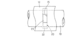
本発明における放電灯装置の第1の実施形態について図1ないし図6を参照しながら説明する。第1の実施形態における放電灯装置は、ガラスバルブの両端部(図示せず)を封止した気密性容器10の内部に希ガスを主体とする放電媒体が封入され、この気密性容器10の一端部または両端部内に第1の電極11が配置され、前記気密性容器10の1か所または複数か所(図面では2か所)を絶縁性のホルダー20が外嵌し、このホルダー20に第2の電極12が備えられた構成となっている。
実施の形態2について、図7および図8を参照しながら説明する。実施の形態2は、気密性容器10の管軸方向におけるホルダー20の板厚aと、同方向における突出部23の幅bとの関係が、a>bに設定されていることを特徴としている。つまり、ホルダー20の板厚が突出部23の幅よりも厚肉となっている。
実施の形態3について、図9および図10を参照しながら説明する。実施の形態3は、ホルダー20について、気密性容器10の管軸方向におけるホルダー20の寸法aについて、気密性容器10からの放射光を放射する側における寸法a1と、第2の電極12が配置される位置で開口16と対向する側における寸法a2との関係がa1<a2に設定されていることを特徴としている。つまり、ホルダー20を正面視ほぼ台形形状に形成し、光照射方向に向けて徐々に薄肉となるようにしている。ホルダー20の突出部23の幅bとの関係は、ホルダー20の剛性確保の観点からa2>bとし、さらに、気密性容器10からの放射光の放射効率を上げる観点から、a1<bとする。
実施の形態4について図11を参照しながら説明する。実施の形態4は、ホルダー20の一つの側面22に離隔部25が形成されていることを特徴としている。この離隔部25は、気密性容器10からの放射光を放射する側、つまり第2の電極12の開口16が設けられる側に形成され、その幅は、気密性容器10の外径よりも狭くされている。このホルダー20の板厚は、実施の形態1同様、図4に示すように突出部23の幅と同じとしてもよいし、実施の形態2および実施の形態3のように突出部23の幅よりも厚肉にしたり光放射方向に向けて薄肉になるようにしてもよい。
実施の形態5について図12を参照しながら説明する。実施の形態5は、角柱状のホルダー20が気密性容器10とほぼ同じ長さに形成され、ホルダー20の中心に気密性容器10を挿入する貫通穴21が形成されていることを特徴としている。ホルダー20の一側面22には、実施の形態4と同様に、気密性容器10の外径よりも狭い幅の離隔部25が形成されている。そして、離隔部25が形成されていない側のホルダー20の3側面22は凵字溝形の第2の電極12に覆われている。ただし、第2の電極12は離隔部25の反対側の面に貼り付けられる帯状としてもよい。いずれにしても、気密性容器10がホルダー20の貫通穴21内に挿入されることにより、気密性容器10とホルダー20に貼り付けられた第2の電極12との間隔は、確実に一定に維持される。
実施の形態6について図13を参照しながら説明する。実施の形態6は、実施の形態5と同様、気密性容器10とほぼ同じ長さの角柱状のホルダー20の中心に気密性容器10を挿入する貫通穴21が形成され、一側面22に気密性容器10の外径よりも狭い幅の離隔部25とが形成されているが、実施の形態5と異なり、第2の電極12が離隔部25の形成されていない側のホルダー20内に埋め込まれていることを特徴としている。第2の電極12がホルダー20内に埋め込まれることにより、気密性容器10と第2の電極12との間隔が実施の形態5よりも近接して一定に維持されるだけでなく、第2の電極12がホルダー20から外れないようにすることができる。第2の電極12は図示したような樋形状のほか帯状とすることもできる。
実施の形態7について図14を参照しながら説明する。実施の形態7は、実施の形態6と同様、気密性容器10とほぼ同じ長さの角柱状のホルダー20の中心に気密性容器10を挿入する貫通穴21が形成され、一側面22に気密性容器10の外径よりも狭い幅の離隔部25とが形成され、第2の電極12が離隔部25の形成されていない側に埋め込まれているが、実施の形態6と異なり、ホルダー20の離隔部25が形成されていない3面または離隔部25の反対側の1面のみに反射部材30が備えられていることを特徴としている。第2の電極12は1本または2本以上の軸状の電極線によって構成される。この構成では、第2の電極12と気密性容器10との間隔を狭くするとともに、反射部14と気密性容器10との間隔を広くすることができる。
11 第1の電極
12 第2の電極
13 蛍光体層
14 反射面
15 嵌合穴
20 ホルダー
21 貫通穴
22 側面
23 突出部
24 離隔部
30 反射部材
Claims (9)
- 希ガスを主体とする放電媒体が気密性容器の内部に封入され、
第1の電極が前記気密性容器の内部に配置され、
反射面を有する第2の電極が前記気密性容器からの放射光を放射するための開口を備えるとともに前記気密性容器から所定の間隔をあけて配置され、
前記所定の間隔を保持する絶縁性のホルダーが前記気密性容器に外嵌される放電装置において、
前記ホルダーは気密性容器を挿通する貫通孔を備えるとともに前記第2の電極が配置される箇所に突出部を備え、
前記第2の電極は、前記ホルダーの突出部と嵌合する嵌合穴を形成したものであることを特徴とする放電灯装置。 - 気密性容器の挿通方向における前記ホルダーの寸法aと、同方向における突出部の寸法bとの関係がa>bに設定されていることを特徴とする請求項1に記載の放電灯装置。
- 気密性容器の挿通方向における前記ホルダーの寸法aについて、気密性容器からの放射光を放射する側における寸法a1と、第2の電極が配置される位置における寸法a2との関係がa1<a2に設定されていることを特徴とする請求項1または2に記載の放電灯装置。
- 前記ホルダーは、透明な材質で気密性容器とほぼ同じ長さに形成されていることを特徴とする請求項1に記載の放電灯装置。
- 前記第2の電極は、前記気密性容器から所定の間隔をあけて前記ホルダー内に埋め込まれていることを特徴とする請求項4に記載の放電灯装置。
- 前記ホルダーは、複数並列に配置され、気密性容器からの放射光を放射する側における角部が連結されていることを特徴とする請求項1から5のいずれか一つに記載の放電灯装置。
- 前記ホルダーは、気密性容器からの放射光を放射する側において気密性容器の外径よりも狭い幅の離隔部が形成されていることを特徴とする請求項1から6のいずれか一つに記載の放電灯装置。
- 前記所定の間隔は、最短が0.1mm以上2.0mm以下であることを特徴とする請求項1から7のいずれか一つに記載の放電灯装置。
- 前記放電媒体は、少なくともキセノンガスを含み、気密性容器の内周面に蛍光体層が積層されていることを特徴とする請求項1から8のいずれか一つに記載の放電灯装置。
Priority Applications (6)
| Application Number | Priority Date | Filing Date | Title |
|---|---|---|---|
| JP2004006596A JP3966284B2 (ja) | 2004-01-14 | 2004-01-14 | 放電灯装置 |
| TW093141111A TW200527476A (en) | 2004-01-14 | 2004-12-29 | Discharge lamp device |
| PCT/JP2005/000005 WO2005069351A1 (ja) | 2004-01-14 | 2005-01-05 | 放電灯装置 |
| EP05703283A EP1705690A4 (en) | 2004-01-14 | 2005-01-05 | DISCHARGE LAMP |
| US10/585,927 US7619361B2 (en) | 2004-01-14 | 2005-01-05 | Discharge lamp device including an airtight container filled with a noble gas |
| CNA2005800024768A CN1910733A (zh) | 2004-01-14 | 2005-01-05 | 放电灯装置 |
Applications Claiming Priority (1)
| Application Number | Priority Date | Filing Date | Title |
|---|---|---|---|
| JP2004006596A JP3966284B2 (ja) | 2004-01-14 | 2004-01-14 | 放電灯装置 |
Publications (3)
| Publication Number | Publication Date |
|---|---|
| JP2005203173A JP2005203173A (ja) | 2005-07-28 |
| JP2005203173A5 JP2005203173A5 (ja) | 2007-03-01 |
| JP3966284B2 true JP3966284B2 (ja) | 2007-08-29 |
Family
ID=34792149
Family Applications (1)
| Application Number | Title | Priority Date | Filing Date |
|---|---|---|---|
| JP2004006596A Expired - Fee Related JP3966284B2 (ja) | 2004-01-14 | 2004-01-14 | 放電灯装置 |
Country Status (6)
| Country | Link |
|---|---|
| US (1) | US7619361B2 (ja) |
| EP (1) | EP1705690A4 (ja) |
| JP (1) | JP3966284B2 (ja) |
| CN (1) | CN1910733A (ja) |
| TW (1) | TW200527476A (ja) |
| WO (1) | WO2005069351A1 (ja) |
Families Citing this family (5)
| Publication number | Priority date | Publication date | Assignee | Title |
|---|---|---|---|---|
| JP4550000B2 (ja) * | 2006-04-04 | 2010-09-22 | 三菱電機株式会社 | 照明ユニット |
| CN101452809B (zh) * | 2007-11-29 | 2010-06-16 | 优志旺电机株式会社 | 双重管型惰性气体荧光灯 |
| US10330827B2 (en) | 2013-04-04 | 2019-06-25 | Sky Motion Research, Ulc | Method and system for displaying weather information on a timeline |
| TWI631361B (zh) | 2013-06-26 | 2018-08-01 | 加拿大商天勢研究無限公司 | 用於在時間軸上顯示氣象資訊之方法及系統 |
| CN111463104B (zh) * | 2020-03-25 | 2022-08-23 | 浙江德清娃哈哈科技创新中心有限公司 | 一种真空紫外光源 |
Family Cites Families (27)
| Publication number | Priority date | Publication date | Assignee | Title |
|---|---|---|---|---|
| DE7831005U1 (de) * | 1978-10-18 | 1979-02-08 | Fa. Martin Hamacher, 4352 Herten | Leuchte |
| JP3532578B2 (ja) * | 1991-05-31 | 2004-05-31 | 三菱電機株式会社 | 放電ランプおよびこれを用いる画像表示装置 |
| EP0517929B1 (de) * | 1991-06-01 | 1995-03-15 | Heraeus Noblelight GmbH | Bestrahlungseinrichtung mit einem Hochleistungsstrahler |
| JPH0529085A (ja) | 1991-07-22 | 1993-02-05 | Toshiba Lighting & Technol Corp | 希ガス放電灯装置 |
| JPH05190150A (ja) | 1992-01-14 | 1993-07-30 | Mitsubishi Electric Corp | 放電ランプ |
| JPH1064478A (ja) | 1996-08-13 | 1998-03-06 | Erebamu:Kk | 冷陰極蛍光放電ランプ及び殺菌ユニット |
| JP3346190B2 (ja) | 1996-10-08 | 2002-11-18 | ウシオ電機株式会社 | 希ガス放電ランプ |
| JPH10188908A (ja) | 1996-12-27 | 1998-07-21 | Toshiba Lighting & Technol Corp | 外面電極蛍光ランプおよび蛍光ランプ装置 |
| JPH10223182A (ja) * | 1997-02-10 | 1998-08-21 | Stanley Electric Co Ltd | 蛍光ランプ |
| US6194821B1 (en) | 1997-02-12 | 2001-02-27 | Quark Systems Co., Ltd. | Decomposition apparatus of organic compound, decomposition method thereof, excimer UV lamp and excimer emission apparatus |
| JP3282798B2 (ja) | 1998-05-11 | 2002-05-20 | クォークシステムズ株式会社 | エキシマランプおよびエキシマ発光装置 |
| EP0948030A3 (en) * | 1998-03-30 | 1999-12-29 | Toshiba Lighting & Technology Corporation | Rare gaseous discharge lamp, lighting circuit, and lighting device |
| JP2000277056A (ja) | 1998-06-29 | 2000-10-06 | Toshiba Lighting & Technology Corp | 希ガス放電ランプ、希ガス放電ランプ点灯装置および照明装置 |
| JP3688915B2 (ja) | 1998-11-27 | 2005-08-31 | 株式会社 日立ディスプレイズ | 液晶表示装置 |
| JP2000285867A (ja) * | 1999-03-31 | 2000-10-13 | Toshiba Lighting & Technology Corp | 放電ランプ装置及び照明装置 |
| JP2001196028A (ja) | 2000-01-07 | 2001-07-19 | Harison Toshiba Lighting Corp | 外面電極放電ランプ |
| JP2001325919A (ja) | 2000-05-16 | 2001-11-22 | Harison Toshiba Lighting Corp | 放電ランプおよび照明装置 |
| JP3857072B2 (ja) | 2000-05-18 | 2006-12-13 | 株式会社日立製作所 | 液晶表示装置 |
| KR100418490B1 (ko) | 2000-05-18 | 2004-02-11 | 가부시키가이샤 히타치세이사쿠쇼 | 액정 표시장치 |
| JP2002093589A (ja) | 2000-09-12 | 2002-03-29 | Harison Toshiba Lighting Corp | 放電ランプ装置および照明装置 |
| JP2002184360A (ja) | 2000-12-12 | 2002-06-28 | Harison Toshiba Lighting Corp | 蛍光ランプ |
| EP1956636A3 (en) * | 2001-03-19 | 2008-09-10 | Fujitsu Limited | Light source device and display device |
| JP2003178717A (ja) | 2001-09-19 | 2003-06-27 | Matsushita Electric Ind Co Ltd | 光源装置およびそれを用いた液晶ディスプレイ |
| EP1296357A2 (en) | 2001-09-19 | 2003-03-26 | Matsushita Electric Industrial Co., Ltd. | Light source device and liquid crystal display employing the same |
| JP3889987B2 (ja) * | 2002-04-19 | 2007-03-07 | パナソニック フォト・ライティング 株式会社 | 放電灯装置及びバックライト |
| KR100434331B1 (ko) * | 2002-05-22 | 2004-06-04 | 엘지.필립스 엘시디 주식회사 | 백 라이트 |
| WO2005022586A1 (ja) * | 2003-08-29 | 2005-03-10 | Matsushita Electric Industrial Co., Ltd. | 光源装置、照明装置、及び液晶表示装置 |
-
2004
- 2004-01-14 JP JP2004006596A patent/JP3966284B2/ja not_active Expired - Fee Related
- 2004-12-29 TW TW093141111A patent/TW200527476A/zh unknown
-
2005
- 2005-01-05 US US10/585,927 patent/US7619361B2/en not_active Expired - Fee Related
- 2005-01-05 CN CNA2005800024768A patent/CN1910733A/zh active Pending
- 2005-01-05 EP EP05703283A patent/EP1705690A4/en not_active Withdrawn
- 2005-01-05 WO PCT/JP2005/000005 patent/WO2005069351A1/ja not_active Application Discontinuation
Also Published As
| Publication number | Publication date |
|---|---|
| CN1910733A (zh) | 2007-02-07 |
| TW200527476A (en) | 2005-08-16 |
| JP2005203173A (ja) | 2005-07-28 |
| US20080061699A1 (en) | 2008-03-13 |
| WO2005069351A1 (ja) | 2005-07-28 |
| EP1705690A8 (en) | 2006-12-06 |
| EP1705690A1 (en) | 2006-09-27 |
| US7619361B2 (en) | 2009-11-17 |
| EP1705690A4 (en) | 2009-11-18 |
Similar Documents
| Publication | Publication Date | Title |
|---|---|---|
| US7282861B2 (en) | Light source device, lighting device and liquid crystal display device | |
| JP3966284B2 (ja) | 放電灯装置 | |
| US7276851B2 (en) | Discharge lamp device and backlight having external electrode unit | |
| JP2001243921A (ja) | 希ガス放電ランプおよび照明装置 | |
| JP2006313734A (ja) | 光源装置、照明装置、及び液晶表示装置 | |
| JP4662358B2 (ja) | 外部電極放電ランプ | |
| US6906461B2 (en) | Light source device with inner and outer electrodes and liquid crystal display device | |
| JP2007073254A (ja) | 外部電極放電ランプ | |
| JP2001118544A (ja) | 外面電極蛍光ランプ | |
| JP4041159B2 (ja) | 誘電体バリア型放電ランプ、バックライト装置、及び液晶表示装置 | |
| KR100392180B1 (ko) | 형광램프와 이를 채용한 백라이트 유니트 | |
| JP2003257378A (ja) | 光源装置および液晶表示装置 | |
| JP4848935B2 (ja) | 二重管型希ガス蛍光ランプ | |
| JP2008004473A (ja) | 冷陰極蛍光ランプ及びバックライト装置 | |
| JP2005174632A (ja) | 光源装置及びこれを用いた液晶ディスプレイ | |
| JP2007095559A (ja) | 発光装置及びこれを用いた液晶表示装置 | |
| JP2008243521A (ja) | 誘電体バリア型放電ランプ | |
| JP2000195466A (ja) | 冷陰極放電ランプおよび照明装置 | |
| JP2000299088A (ja) | 外面電極蛍光ランプおよび照明装置 | |
| JP2005005186A (ja) | 光源装置 | |
| KR20060016422A (ko) | 외부전극 형광램프 | |
| JP2000223079A (ja) | 蛍光ランプおよび照明装置 | |
| JP2003123701A (ja) | 冷陰極蛍光ランプおよび照明装置 | |
| JPH11307049A (ja) | 蛍光ランプおよび照明装置 | |
| JP2005332649A (ja) | 光源装置及びこれを用いた液晶ディスプレイ |
Legal Events
| Date | Code | Title | Description |
|---|---|---|---|
| A521 | Request for written amendment filed |
Free format text: JAPANESE INTERMEDIATE CODE: A523 Effective date: 20070115 |
|
| A621 | Written request for application examination |
Free format text: JAPANESE INTERMEDIATE CODE: A621 Effective date: 20070115 |
|
| A871 | Explanation of circumstances concerning accelerated examination |
Free format text: JAPANESE INTERMEDIATE CODE: A871 Effective date: 20070115 |
|
| A975 | Report on accelerated examination |
Free format text: JAPANESE INTERMEDIATE CODE: A971005 Effective date: 20070201 |
|
| RD01 | Notification of change of attorney |
Free format text: JAPANESE INTERMEDIATE CODE: A7421 Effective date: 20070214 |
|
| A131 | Notification of reasons for refusal |
Free format text: JAPANESE INTERMEDIATE CODE: A131 Effective date: 20070220 |
|
| A521 | Request for written amendment filed |
Free format text: JAPANESE INTERMEDIATE CODE: A523 Effective date: 20070409 |
|
| TRDD | Decision of grant or rejection written | ||
| A01 | Written decision to grant a patent or to grant a registration (utility model) |
Free format text: JAPANESE INTERMEDIATE CODE: A01 Effective date: 20070508 |
|
| A61 | First payment of annual fees (during grant procedure) |
Free format text: JAPANESE INTERMEDIATE CODE: A61 Effective date: 20070521 |
|
| FPAY | Renewal fee payment (event date is renewal date of database) |
Free format text: PAYMENT UNTIL: 20100608 Year of fee payment: 3 |
|
| LAPS | Cancellation because of no payment of annual fees |