JP3865978B2 - Substrate processing equipment - Google Patents
Substrate processing equipment Download PDFInfo
- Publication number
- JP3865978B2 JP3865978B2 JP27471399A JP27471399A JP3865978B2 JP 3865978 B2 JP3865978 B2 JP 3865978B2 JP 27471399 A JP27471399 A JP 27471399A JP 27471399 A JP27471399 A JP 27471399A JP 3865978 B2 JP3865978 B2 JP 3865978B2
- Authority
- JP
- Japan
- Prior art keywords
- substrate
- processing apparatus
- transport
- processing liquid
- width direction
- Prior art date
- Legal status (The legal status is an assumption and is not a legal conclusion. Google has not performed a legal analysis and makes no representation as to the accuracy of the status listed.)
- Expired - Fee Related
Links
Images


Landscapes
- Container, Conveyance, Adherence, Positioning, Of Wafer (AREA)
- Exposure Of Semiconductors, Excluding Electron Or Ion Beam Exposure (AREA)
- Cleaning Or Drying Semiconductors (AREA)
- Cleaning By Liquid Or Steam (AREA)
- Weting (AREA)
Abstract
Description
【0001】
【発明の属する技術分野】
本発明は、液晶表示装置用ガラス基板、プリント基板、プラズマディスプレイ用基板等の板状の基板(以下、基板と呼ぶ)に対して処理液を供給して処理をおこなう基板処理装置に関し、さらに詳しくは、基板を傾斜姿勢で搬送しながら、基板の上端縁部から現像液、エッチング液、剥離液、リンス液、等の処理液を供給して基板を処理する基板処理装置に関する。
【0002】
【従来の技術】
従来より、基板を傾斜姿勢で搬送しながら、基板上端縁部から処理液ノズルにより基板表面へ処理液を供給して基板の処理をおこなう基板処理装置が知られている。このような傾斜搬送式の基板処理装置は、基板上の液の置換が迅速におこなわれる他、液切れが良好となるなどの優れた効果を奏する。
【0003】
しかし、基板処理装置は、基板処理装置毎に処理される基板寸法が異なることが多いため、このような基板処理装置は、すべての基板寸法に対応して処理できるようにする必要がある。
【0004】
しかし、従来の傾斜式基板処理装置においては、基板上端縁部の処理液ノズルの位置、または、搬送される基板の下端縁部を支持する支持ローラのいずれかの位置を、処理される基板寸法に対応させて配置しなければならず、処理される基板の寸法毎に、処理液ノズルの位置、または、搬送される基板の下端縁部を支持する支持ローラの、いずれかの配置が異なる複数種の基板処理装置を用意しなければならないという問題があった。
【0005】
このような問題を解決するために、特開平09−232268号公報においては、搬送される基板の幅寸法に応じて基板の上位側位置を一致させるべく、基板の下位側端縁を支持する支持ローラを、基板搬送ローラと平行な方向(処理液ノズル方向)へ移動可能にする装置が提案されている。
【0006】
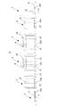
図4は特開平09−232268号公報において提案された装置を表す模式図である。図4において、処理槽40内には複数の搬送ローラ100が設けられており、その軸心が基板Cの搬送方向に対して直交する面内であって、水平方向に対して傾斜して等ピッチで配置され、図示しない駆動手段により同期して回転するように構成されている。
【0007】
処理槽40内に搬送されてきた基板Cは、搬送ローラ100に設けられた中央支持ローラ130上に載置されるとともに、基板Cの下端縁部を支持する支持ローラ150の周面に、基板Cの下端縁部を支持されながら処理槽40内を搬送される。
【0008】
支持ローラ150は、回転軸140に回転自在に軸支されており、回転軸140は、側板160に固設された軸受け部200に軸支されたネジ軸110に螺合された可動支持体190に固設されている。ネジ軸110は図示しない駆動部により回転自在に構成されており、ネジ軸110が回転すると、ネジ軸110に螺合された可動支持体190が移動することで、支持ローラ150をネジ軸110の軸方向に沿って移動できるように構成されている。
【0009】
基板Cの寸法に合わせて、支持ローラ150の基板支持位置を調整する場合は、ネジ軸110を回転させて可動支持体190の位置を移動するだけで、基板寸法に合わせた位置調整がおこなえるので、基板寸法毎に基板処理装置を用意する必要がなく、装置設計を標準化することが可能となり生産性も向上する。
【0010】
一方、このような基板処理装置で処理される基板寸法は、基板処理装置毎に異なることは多いものの、同一の基板処理装置で処理する基板寸法を変更するケースは少ない。ところが、複数の基板寸法に対応するため、前述のように、処理する基板寸法に対応して、基板Cの下端縁部を支持する支持ローラ150の基板支持位置を切り替えるための機構を設けねばならず、機構が複雑化するとともにコストが高くなるという問題があった。
【0011】
本発明は、上記のような問題点を解決するためになされたものであり、複雑な切替機構を設けることなく処理することが可能であるとともに、もし、必要により基板寸法を変更する場合も、簡易に基板の寸法変更に対応できる基板処理装置を提供することを目的とする。
【0012】
【課題を解決するための手段】
請求項1に記載の発明は、基板を所定の搬送方向に搬送しつつその表面に処理液を供給して基板の表面処理を行う基板処理装置において、表面処理されるべき基板を、上記搬送方向に直交する幅方向について水平状態から所定の角度だけ傾斜させつつ搬送する傾斜搬送手段と、傾斜搬送手段により傾斜させられつつ搬送される基板の上記幅方向の上端よりも基板外方の位置において、傾斜させられつつ搬送される基板に供給すべき処理液を吐出する処理液供給手段と、処理液供給手段から吐出された処理液を、傾斜させられつつ搬送される基板の上記幅方向の上端に供給するべく案内する処理液案内手段と、を備えたことを特徴とする。
【0013】
請求項2に記載の発明は、処理液案内手段は、表面処理されるべき基板の幅方向の寸法に応じて交換可能であることを特徴とする。
【0014】
請求項3に記載の発明は、基板を所定の搬送方向に搬送しつつその表面に処理液を供給して基板の表面処理を行う基板処理装置において、表面処理されるべき基板を、上記搬送方向に直交する幅方向について水平状態から所定の角度だけ傾斜させつつ搬送する傾斜搬送手段と、傾斜搬送手段により傾斜させられつつ搬送される基板の上記幅方向の上端よりも基板外方の位置において、傾斜させられつつ搬送される基板に供給すべき処理液を吐出する処理液供給手段と、上記幅方向における予め定められた位置に固定され、傾斜搬送手段によって搬送される基板の上記幅方向の上端に、処理液供給手段から吐出される処理液を案内する処理液案内手段と、を備えたことを特徴とする。
【0015】
請求項4に記載の発明は、処理液供給手段は搬送方向に延びる吐出口を備え、吐出口の搬送方向の長さに応じて処理液案内手段も搬送方向に延びていることを特徴とする。
【0016】
請求項5に記載の発明は、処理液供給手段は、上記搬送方向に延びるスリットからなる吐出口を備えることを特徴とする。
【0017】
請求項6に記載の発明は、処理液供給手段は、上記搬送方向に延びるシャワーパイプであることを特徴とする。
【0018】
請求項7に記載の発明は、処理液案内手段は、傾斜させられつつ搬送される基板の上面とほぼ平行な上面を有することを特徴とする。
【0019】
請求項8に記載の発明は、処理液案内手段の上記幅方向の下端は、傾斜させられつつ搬送される基板の上記幅方向の上端に重なるように配置されていることを特徴とする。
【0020】
請求項9に記載の発明は、上記幅方向において、案内板の下端は、傾斜させられつつ搬送される基板の上端との間に所定の間隔を形成するように配置されていることを特徴とする。
【0021】
請求項10に記載の発明は、傾斜搬送手段は、上記搬送方向に直交する幅方向について水平状態から所定の角度だけ傾斜させられて互いに平行に配置され、その上に載置された基板を傾斜させつつ搬送方向に搬送するために互いに同期して回転させられる複数の搬送ローラと、搬送ローラによって傾斜させられつつ搬送方向に搬送される基板の幅方向の下端を支持して基板の傾斜姿勢を規制し、基板を傾斜させつつ搬送方向に搬送するために回転させられる複数の支持ローラと、を備えたことを特徴とする。
【0022】
請求項11に記載の発明は、複数の搬送ローラと複数の支持ローラとは、搬送方向について交互に配置されていることを特徴とする。
【0023】
【発明の実施の形態】
以下、本発明を液晶用角形ガラス基板の処理をおこなう基板処理装置に適用した場合を例として、図面に基づいて実施の形態を説明する。
【0024】
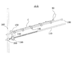
図1は本発明に係る基板処理装置1の一実施形態を示す概略構成図である。図1において、基板処理装置1は、前工程から搬送されてきた基板Aを受け入れる基板導入部2と、基板導入部2から水平姿勢で搬送されてきた基板Aを傾斜姿勢に変更する姿勢変更部3と、傾斜姿勢で搬送されてきた基板Aの上部から処理液を供給して処理をおこなう処理部4と、処理液により処理された基板Aの上部からリンス液を供給してリンスをおこなうリンス部5と、リンス処理された基板Aを傾斜姿勢から水平姿勢に変更する姿勢変更部6と、水平姿勢に変更された基板Aをエアナイフ12により乾燥して次工程に導出する乾燥部7とが直列に配設されて形成されている。
【0025】
そして基板処理装置1は、基板導入部2、姿勢変更部3、処理部4、リンス部5、姿勢変更部6、乾燥部7の順に基板Aを搬送しつつ基板Aに所定の処理を施すものである。
【0026】
本実施形態では、基板Aを搬送する基板搬送手段としてローラコンベアが適用されている。このローラコンベアは、基板Aの搬送方向(図1の左方から右方に向かう方向)に直交する方向に支持軸を配した複数の搬送ローラ10が、等ピッチで搬送方向に並設配置されて構成されている。
【0027】
この搬送ローラ10の並設ピッチは、基板Aの搬送方向の寸法に対応して等ピッチに設定され、これによって、基板Aは複数の搬送ローラ10によって支持され得るようにしている。そして、回転駆動している複数の搬送ローラ10上に基板Aを載置することにより、基板Aは各搬送ローラ10の同期回転に伴って搬送方向(図1の右方)に向けて搬送されるようになっている。
【0028】
基板Aは、前工程からコンベアあるいはロボット等の上流側引継手段を介して基板導入部2に移され、ついで水平に等ピッチで配設された搬送ローラ10aの駆動によって、基板導入部2から姿勢変更部3へと水平搬送されて停止する。姿勢変更部3では、図示しない駆動手段により搬送ローラ10bを傾斜姿勢に姿勢変更した後に、搬送ローラ10bの駆動を再開して処理部4へと基板Aを移送する。処理部4では、基板Aは搬送ローラ10cによって傾斜姿勢で搬送されつつ所定の処理が施された後、リンス部5に移送される。リンス部5において、基板Aは搬送ローラ10dにより傾斜姿勢で搬送されつつ、基板Aに付着した処理液をリンスされた後に、姿勢変更部6に移送されて停止する。姿勢変更部6では、図示しない駆動手段により、搬送ローラ10eを傾斜姿勢から水平姿勢に姿勢変更した後、搬送ローラ10eの駆動を再開して基板Aを乾燥部7へと移送する。乾燥部7では、基板Aを搬送ローラ10fにより水平に搬送させながら、乾燥部7に設けられたエアーナイフ12によって、基板Aの表面に付着したリンス液を乾燥させる。その後、乾燥部7の下流側で、コンベアあるいはロボット等からなる下流側引継手段を介して、次行程に向けて導出されるようになっている。
【0029】
処理部4とリンス部5内において、上記各搬送ローラ10c、10dは、その軸心が基板Aの搬送方向に対して直交する面内であって、水平方向に対して傾斜して設けられている。
【0030】
処理部4およびリンス部5内の、各搬送ローラ10の傾斜角度は全て同一角度に設定されており、本実施形態では15゜に設定している。これら搬送ローラ10の上部に基板Aが通過する基板搬送経路が形成され、これによって、基板Aは処理部4およびリンス部5内において傾斜姿勢で基板搬送経路を搬送されつつ、所定の処理が施されるようになっている。また、詳細な説明は省略するが、リンス部5は処理部4と同一の構成となっている。
【0031】
図2は、本発明に係る図1の基板処理装置1における、処理部4を搬送方向から見た様子を示す模式図であり、図2の(a)は全体を表し、図2の(b)はその要部を拡大したものである。
【0032】
図2の(a)において、処理部4内では、搬送ローラ10cがその両端部を側板16と側板17に設けられた軸受け部により軸支されて、基板Aの搬送方向に沿って傾斜姿勢で複数並設されており、図示しない駆動手段により同方向へ回転駆動するように構成されている。また、搬送ローラ10cには、中央支持ローラ13が搬送される基板Aの寸法に応じて等ピッチで並設されている。
【0033】
搬送ローラ10cの中央支持ローラ13は、処理される基板Aを支持するのに必要な範囲にのみ設ければ良いので、搬送ローラ10cは中央支持ローラ13の取り付け位置と個数を調整するのみで、搬送方向と直交する方向の幅寸法(以下、幅寸法と称する。)が異なる複数種の基板Aに対応することができる。
【0034】
次に、搬送ローラ10cの下方位置には、並設配置された各搬送ローラ10cの中間位置に支持ローラ15が設けられている。支持ローラ15は、側板16に固設された基部19の、回転軸14に回転自在に軸支されており、搬送ローラ10cにより搬送される基板Aの下端縁部を支持しながら回転することで、基板Aを基板搬送経路に沿って搬送するように構成されている。処理部4に搬送される基板Aは、基板Aの幅寸法にかかわらず、支持ローラ15との接線位置を基板Aの下端側基準位置として搬送される。このように、搬送ローラ10cと支持ローラ15とを交互に配設することによって、搬送ローラと駆動部との接続空間が広くとれるので、駆動部との接続が容易となる。
【0035】
搬送ローラ10cの上部には、基板Aの搬送方向に沿って延設された吐出口が形成されたスリットノズル8が設けられおり、その吐出口は、基板の幅寸法が、基板処理装置1で処理可能な最大幅寸法の基板B(以下、基板Bと称する)の、上部端縁に向けて処理液を供給するように配置されている。
【0036】
上記スリットノズル8の下方には、基板Aの幅寸法が、最大幅寸法の基板Bよりも短い場合に、スリットノズル8から供給される処理液を、基板Aに案内するための処理液案内手段として、案内板20が配置されている。
【0037】
次に図2の(b)により、案内板20を中心として、スリットノズル8と基板Aとの関係を詳細に説明する。図2(b)において、案内板20は、側板17に一方を固設された支持部材18の、下方向他端側にネジ21で固定されている。また、案内板20は、搬送方向と直交する方向の幅寸法が、基板処理装置1により搬送可能な最大幅寸法の基板B(破線にて記載)の、搬送方向に沿った上端縁部位置Wから、基板Bより幅寸法の短い基板Aの、搬送方向に沿った上端縁部位置Yと、上端縁部位置Y側の搬送方向に沿った有効領域位置P(以下、「上端部側有効領域位置P」と称する。)との中間を下端縁部位置Zとする幅寸法で、基板Aの搬送面に対向して平行に重なるように配置された板状材が用いられている。
【0038】
本実施形態においては、基板Aの上端縁部位置Yから、基板Aの上端部側有効領域位置Pまでの寸法は10mmとし、案内板20の下端縁部位置Zは、基板Aの下端縁部位置Yの5mm下方に設定されている。また、案内板20と基板Aとの重なり部分は、平行に配置されているので、基板Aを搬送中も接触することはない。
【0039】
また、案内板20の上方にはスリットノズル8が配置されており、スリットノズル8には搬送方向に延びるスリットからなる吐出口が形成されている。吐出口から吐出された処理液は、案内板20の上端縁位置Wに向けて処理液を供給するように配置されている。スリットノズル8より供給された処理液は、案内板20により基板Aの幅方向における上端端縁部位置Yと、基板Aの上端縁部側有効領域位置Pとの中間まで案内され、基板A上に供給される。また、スリットノズル8の吐出口の搬送方向の長さに応じて、案内板20も搬送方向に延びる。
【0040】
以上のように、基板処理装置1で処理される基板Aの、搬送方向と直交する方向の幅寸法が、基板処理装置1で処理できる最大幅寸法の基板Bより小さな場合でも、その寸法差に応じた案内板20を設けるのみで処理することができるので、従来のように、基板Aの下端を支持する支持ローラ150の位置を変更する機構を設けることなく、幅寸法の異なる複数の基板Aを処理することができる。また、必要により幅寸法の異なる基板Aを処理したい場合も、幅寸法の異なる案内板20へ変更するのみで処理が可能となる。
【0041】
次に図3は、本発明に係る図1の基板処理装置1の、別の実施形態における処理部4を搬送方向から見た様子を示す模式図であり、その要部を拡大したものである。
【0042】
本実施形態においては、前述した図2の実施形態と共通する部分については説明を省略し、相違する部分を中心に説明する。
【0043】
図3の実施形態においては、図2の実施形態で説明した案内板20の配置が異なり、案内板20は、搬送方向と直交する方向の幅寸法が最大寸法の基板B(破線にて図示)における、搬送方向に沿った上端縁部位置Wから、基板Aの搬送方向に沿った上端縁部位置Yに近接した下端縁部位置Zまでの幅寸法で、その下端側面が基板Aの上端側面に対向して近接配置された板状材である点が、前述の実施形態と異なる。
【0044】
本実施形態において、案内板20の下端側側面と、基板Aの上端側側面との距離dは、案内板20にスリットノズル8から供給された処理液が、案内板20の下端側側面と基板Aの上端側側面との間にこぼれ落ちにくく、また、搬送中の基板Aが、案内板20に接触しない距離に設定されており、本実施形態では3mmに設定されている。この距離は使用される処理液の粘度や流速によっても変化するが、案内板20の下端側側面と、基板Aの上端側側面との間に処理液が少量こぼれ落ちても、基板Aの処理に充分な処理液が供給されるように、処理液の流量と流速を調整すれば良い。
【0045】
本発明は、上記の実施形態に限定されるものではなく、以下の内容をも包含するものである。
【0046】
(1)本実施形態においては、処理部4とリンス部5においてスリットノズル8を使用したが、スリットノズル8に変えて、搬送方向に延びるシャワーパイプを用いても良く、リンス部5のみシャワーパイプを用いても良い。
【0047】
(2)本実施形態においては、案内板20は側板17に固定された支持部材18に固定されているが、案内板20を支持部材18に着脱自在に構成すれば、より容易に基板Aの幅寸法変更に対応させることができる。
【0048】
(3)本実施形態においては、搬送ローラ10に設けられた中央支持ローラ13の取り付け位置を、基板Aの幅に対応させて配置しているが、最大幅寸法の基板Bの幅に対応させて配置すれば、基板Aの幅に対応させて中央支持ローラ13の取り付け位置を変更する必要がなく、寸法幅の異なる基板への変更作業がより容易となる。
【0049】
(4)本実施形態においては、処理液供給手段から基板に処理液を供給する所定位置を、最大幅寸法の基板Bの上端縁位置としたが、これに限定されるものでなく、最大幅寸法の基板Bの上端縁位置より、更に基板の幅方向上部位置を処理液の供給位置とし、該供給位置から案内手段により基板上端縁部へ処理液を案内するように構成してもよい。
【0050】
【発明の効果】
請求項1に記載の発明によれば、基板寸法に対応した処理液案内手段を設けるのみで処理が可能となり、基板処理装置を簡素化することができる。
【0051】
請求項2に記載の発明によれば、基板の幅寸法に応じて処理液案内手段を交換できるように構成したので、幅寸法の異なる基板であっても、基板処理装置の構成を変更したり、複雑な切替機構を設けることなく、簡易な構成で基板の幅寸法変更が行える。
【0052】
請求項3に記載の発明によれば、請求項2に記載の発明のような、基板の幅寸法に応じて処理液案内手段を交換するだけで、簡易な構成で基板の幅寸法変更が行えるという効果は得られないが、基板寸法に対応した処理液案内手段を設けるのみで処理液供給手段の位置から基板の幅方向上端に処理液を案内供給して処理できる。
【0053】
請求項4に記載の発明によれば、処理液案内手段の搬送方向に延びる吐出口の長さに応じて処理液案内手段の長さを変更するのみで、基板の搬送方向の寸法変更に容易に対応することができる。
【0054】
請求項5に記載の発明によれば、処理液供給手段がスリットからなる吐出口を備えるので、基板表面へ均一に処理液を供給できる。
【0055】
請求項6に記載の発明によれば、処理液供給手段としてシャワーパイプを用いて、基板表面へ均一に処理液を供給できる。
【0056】
請求項7に記載の発明によれば、処理液案内手段の上面を、基板の上面と平行に配置したので、より均一に処理液を供給することができる。
【0057】
請求項8に記載の発明によれば、案内板の下端が基板の上端と重なるように配置したので、基板が搬送中に案内板に接触して、基板に傷が生じることがない。
【0058】
請求項9に記載の発明によれば、案内板の下端と基板の上端との間に所定の間隔を設けて配置したので、基板が搬送中に処理液案内手段に接触して、基板に傷が生じることがない。
【0059】
請求項10に記載の発明によれば、基板を傾斜姿勢で搬送できるように構成したので、装置の設置面積を少なくすることができる。
【0060】
請求項11に記載の発明によれば、搬送ローラと支持ローラを交互に配設したので、搬送ローラ駆動機構の取り付けが容易になる。
【図面の簡単な説明】
【図1】本発明に係る基板処理装置の一実施形態を示す概略構成図である。
【図2】本発明に係る基板処理装置の処理部を搬送方向から見た様子を示す図である。
【図3】本発明に係る基板処理装置の別の実施形態における処理部を搬送方向から見た様子を示す図である。
【図4】従来装置を示した模式図である。
【符号の説明】
A 基板
B 最大寸法の基板
P 上端縁部側有効領域位置
W 基板Bの上端縁部位置
Y 基板Aの上端縁部位置
Z 処理液案内手段の下端縁部位置
1 基板処理装置
2 基板導入部
3 姿勢変更部
4 処理部 5 リンス部
6 姿勢変更部
7 乾燥部
8 スリットノズル
10 搬送ローラ
13 中央支持ローラ
15 支持ローラ
18 支持部材
20 案内板[0001]
BACKGROUND OF THE INVENTION
The present invention relates to a substrate processing apparatus that supplies a processing liquid to a plate-like substrate (hereinafter referred to as a substrate) such as a glass substrate for a liquid crystal display device, a printed circuit board, or a plasma display substrate, and performs processing. Relates to a substrate processing apparatus for processing a substrate by supplying a processing solution such as a developing solution, an etching solution, a stripping solution, or a rinsing solution from the upper edge of the substrate while transporting the substrate in an inclined posture.
[0002]
[Prior art]
2. Description of the Related Art Conventionally, there has been known a substrate processing apparatus for processing a substrate by supplying a processing liquid from a substrate upper end edge to a substrate surface by a processing liquid nozzle while conveying the substrate in an inclined posture. Such an inclined conveyance type substrate processing apparatus provides excellent effects such as quick replacement of the liquid on the substrate and good liquid breakage.
[0003]
However, since substrate processing apparatuses often have different substrate dimensions to be processed for each substrate processing apparatus, it is necessary for such a substrate processing apparatus to be able to process all substrate dimensions.
[0004]
However, in the conventional tilted substrate processing apparatus, the position of the processing liquid nozzle at the upper edge of the substrate or the position of the support roller that supports the lower edge of the substrate to be transported is the size of the substrate to be processed. The position of the processing liquid nozzle or the support roller that supports the lower edge of the substrate to be transported is different for each dimension of the substrate to be processed. There has been a problem that it is necessary to prepare a kind of substrate processing apparatus.
[0005]
In order to solve such a problem, Japanese Patent Application Laid-Open No. 09-232268 discloses a support for supporting the lower side edge of the substrate so as to match the upper side position of the substrate in accordance with the width dimension of the substrate to be transported. An apparatus has been proposed that enables a roller to move in a direction parallel to the substrate transport roller (in the direction of the processing liquid nozzle).
[0006]
FIG. 4 is a schematic diagram showing an apparatus proposed in Japanese Patent Application Laid-Open No. 09-232268. In FIG. 4, a plurality of
[0007]
The substrate C that has been transported into the
[0008]
The
[0009]
When adjusting the substrate support position of the
[0010]
On the other hand, although the substrate dimensions processed by such a substrate processing apparatus often differ from one substrate processing apparatus to another, there are few cases where the dimensions of a substrate processed by the same substrate processing apparatus are changed. However, in order to cope with a plurality of substrate dimensions, as described above, a mechanism for switching the substrate support position of the
[0011]
The present invention has been made to solve the above problems, and can be processed without providing a complicated switching mechanism, and if the substrate dimensions are changed as necessary, It is an object of the present invention to provide a substrate processing apparatus that can easily cope with a change in dimensions of a substrate.
[0012]
[Means for Solving the Problems]
The invention according to
[0013]
The invention as set forth in
[0014]
According to a third aspect of the present invention, there is provided a substrate processing apparatus for performing a surface treatment of a substrate by supplying a treatment liquid to the surface of the substrate while conveying the substrate in a predetermined conveyance direction. Inclined transport means for transporting while being inclined at a predetermined angle from the horizontal state in the width direction perpendicular to the horizontal direction, and at a position outside the substrate from the upper end in the width direction of the substrate being transported while being tilted by the tilt transport means, a processing liquid supplying means for discharging a processing liquid to be supplied to the substrate to be conveyed while being tilted, is fixed at a predetermined position in the width direction, the upper end of the width direction of the substrate transported by the inclined transporting unit And a processing liquid guide means for guiding the processing liquid discharged from the processing liquid supply means.
[0015]
According to a fourth aspect of the present invention, the processing liquid supply means includes a discharge port extending in the transport direction, and the processing liquid guide means extends in the transport direction according to the length of the discharge port in the transport direction. .
[0016]
According to a fifth aspect of the present invention, the processing liquid supply means includes a discharge port including a slit extending in the transport direction.
[0017]
The invention described in
[0018]
The invention described in claim 7 is characterized in that the processing liquid guiding means has an upper surface substantially parallel to the upper surface of the substrate which is conveyed while being inclined.
[0019]
The invention described in
[0020]
The invention according to claim 9 is characterized in that, in the width direction, the lower end of the guide plate is disposed so as to form a predetermined interval with the upper end of the substrate being conveyed while being inclined. To do.
[0021]
According to a tenth aspect of the present invention, the inclined conveying means is arranged in parallel with each other by being inclined by a predetermined angle from a horizontal state with respect to the width direction orthogonal to the conveying direction, and the substrate placed thereon is inclined. And supporting a lower end of the substrate in the width direction of the substrate being conveyed in the conveyance direction while being inclined by the conveyance roller to support the inclined posture of the substrate. And a plurality of support rollers that are rotated to convey the substrate in the conveyance direction while tilting the substrate.
[0022]
The invention according to claim 11 is characterized in that the plurality of transport rollers and the plurality of support rollers are alternately arranged in the transport direction.
[0023]
DETAILED DESCRIPTION OF THE INVENTION
Embodiments will be described below with reference to the drawings, taking as an example the case where the present invention is applied to a substrate processing apparatus for processing a rectangular glass substrate for liquid crystal.
[0024]
FIG. 1 is a schematic configuration diagram showing an embodiment of a
[0025]
The
[0026]
In the present embodiment, a roller conveyor is applied as the substrate transport means for transporting the substrate A. In this roller conveyor, a plurality of transport rollers 10 having support shafts arranged in a direction perpendicular to the transport direction of substrate A (the direction from the left to the right in FIG. 1) are arranged in parallel in the transport direction at an equal pitch. Configured.
[0027]
The parallel pitch of the transport rollers 10 is set to an equal pitch corresponding to the dimension in the transport direction of the substrate A, whereby the substrate A can be supported by a plurality of transport rollers 10. Then, by placing the substrate A on the plurality of rotationally driven transport rollers 10, the substrate A is transported in the transport direction (right side in FIG. 1) with the synchronous rotation of the transport rollers 10. It has become so.
[0028]
The substrate A is transferred from the previous process to the
[0029]
In the
[0030]
The inclination angles of the conveying rollers 10 in the
[0031]
FIG. 2 is a schematic view showing a state in which the
[0032]
In FIG. 2A, in the
[0033]
Since the
[0034]
Next, a
[0035]
A
[0036]
Below the
[0037]
Next, with reference to FIG. 2B, the relationship between the
[0038]
In the present embodiment, the dimension from the upper end edge position Y of the substrate A to the upper end side effective region position P of the substrate A is 10 mm, and the lower end edge position Z of the
[0039]
A
[0040]
As described above, even when the width dimension of the substrate A processed in the
[0041]
Next, FIG. 3 is a schematic view showing a state in which the
[0042]
In the present embodiment, description of parts common to the above-described embodiment of FIG. 2 will be omitted, and different parts will be mainly described.
[0043]
In the embodiment of FIG. 3, the arrangement of the
[0044]
In this embodiment, the distance d between the lower end side surface of the
[0045]
The present invention is not limited to the above embodiment, and includes the following contents.
[0046]
(1) In the present embodiment, the
[0047]
(2) In this embodiment, the
[0048]
(3) In this embodiment, the mounting position of the
[0049]
(4) In the present embodiment, the predetermined position at which the processing liquid is supplied from the processing liquid supply means to the substrate is the upper edge position of the substrate B having the maximum width dimension. from the upper edge position of the substrate B dimensions, further a supply position of the processing liquid in the width direction upper position of the substrate, may be configured to guide the process liquid to the substrate upper edge by the guide means from the 該供 supply position .
[0050]
【The invention's effect】
According to the first aspect of the present invention, it is possible to perform processing only by providing the processing liquid guiding means corresponding to the substrate size, and the substrate processing apparatus can be simplified.
[0051]
According to the second aspect of the present invention, since the processing liquid guiding means can be replaced according to the width dimension of the substrate, the configuration of the substrate processing apparatus can be changed even for substrates having different width dimensions. The width of the substrate can be changed with a simple configuration without providing a complicated switching mechanism.
[0052]
According to the invention described in claim 3, as in the invention described in
[0053]
According to the fourth aspect of the present invention, it is easy to change the size of the substrate in the transport direction only by changing the length of the treatment liquid guide means in accordance with the length of the discharge port extending in the transport direction of the process liquid guide means. It can correspond to.
[0054]
According to the fifth aspect of the present invention, since the processing liquid supply means includes the discharge port formed of a slit, the processing liquid can be uniformly supplied to the substrate surface.
[0055]
According to the sixth aspect of the present invention, the processing liquid can be uniformly supplied to the substrate surface using the shower pipe as the processing liquid supply means.
[0056]
According to the seventh aspect of the invention, since the upper surface of the processing liquid guiding means is arranged in parallel with the upper surface of the substrate, the processing liquid can be supplied more uniformly.
[0057]
According to the eighth aspect of the invention, since the lower end of the guide plate is arranged so as to overlap the upper end of the substrate, the substrate does not come into contact with the guide plate during conveyance and the substrate is not damaged.
[0058]
According to the ninth aspect of the present invention, since the predetermined distance is provided between the lower end of the guide plate and the upper end of the substrate, the substrate comes into contact with the processing liquid guide means during transportation, and the substrate is damaged. Will not occur.
[0059]
According to the tenth aspect of the present invention, since the substrate can be transported in an inclined posture, the installation area of the apparatus can be reduced.
[0060]
According to the eleventh aspect of the present invention, since the conveying roller and the supporting roller are alternately arranged, it is easy to attach the conveying roller driving mechanism.
[Brief description of the drawings]
FIG. 1 is a schematic configuration diagram showing an embodiment of a substrate processing apparatus according to the present invention.
FIG. 2 is a diagram illustrating a state in which a processing unit of the substrate processing apparatus according to the present invention is viewed from a transport direction.
FIG. 3 is a diagram illustrating a state in which a processing unit in another embodiment of the substrate processing apparatus according to the present invention is viewed from a transport direction.
FIG. 4 is a schematic diagram showing a conventional apparatus.
[Explanation of symbols]
A Substrate B Maximum size substrate P Upper edge side effective area position W Upper edge position of substrate B Y Upper edge position of substrate A Z Lower edge position of processing liquid guiding means 1
Claims (11)
表面処理されるべき基板を、上記搬送方向に直交する幅方向について水平状態から所定の角度だけ傾斜させつつ搬送する傾斜搬送手段と、
傾斜搬送手段により傾斜させられつつ搬送される基板の上記幅方向の上端よりも基板外方の位置において、傾斜させられつつ搬送される基板に供給すべき処理液を吐出する処理液供給手段と、
処理液供給手段から吐出された処理液を、傾斜させられつつ搬送される基板の上記幅方向の上端に供給するべく案内する処理液案内手段と、
を備えたことを特徴とする基板処理装置。In a substrate processing apparatus for performing a surface treatment of a substrate by supplying a treatment liquid to the surface of the substrate while conveying the substrate in a predetermined conveyance direction,
An inclined conveyance means for conveying the substrate to be surface-treated while being inclined by a predetermined angle from a horizontal state in the width direction orthogonal to the conveyance direction;
A processing liquid supply means for discharging a processing liquid to be supplied to the substrate to be conveyed while being inclined at a position outside the substrate from the upper end in the width direction of the substrate being conveyed while being inclined by the inclined conveying means;
The process liquid supply unit processing liquid discharged from the treatment liquid guide means for guiding so as to supply to the upper end of the width direction of the substrate which is transported while being tilted,
A substrate processing apparatus comprising:
表面処理されるべき基板を、上記搬送方向に直交する幅方向について水平状態から所定の角度だけ傾斜させつつ搬送する傾斜搬送手段と、
傾斜搬送手段により傾斜させられつつ搬送される基板の上記幅方向の上端よりも基板外方の位置において、傾斜させられつつ搬送される基板に供給すべき処理液を吐出する処理液供給手段と、
上記幅方向における予め定められた位置に固定され、傾斜搬送手段によって搬送される基板の上記幅方向の上端に、処理液供給手段から吐出される処理液を案内する処理液案内手段と、
を備えたことを特徴とする基板処理装置。In a substrate processing apparatus for performing a surface treatment of a substrate by supplying a treatment liquid to the surface of the substrate while conveying the substrate in a predetermined conveyance direction,
An inclined conveyance means for conveying the substrate to be surface-treated while being inclined by a predetermined angle from a horizontal state in the width direction orthogonal to the conveyance direction;
A processing liquid supply means for discharging a processing liquid to be supplied to the substrate to be conveyed while being inclined at a position outside the substrate from the upper end in the width direction of the substrate being conveyed while being inclined by the inclined conveying means;
Is fixed to a predetermined position in the width direction, the upper end of the width direction of the substrate which is transported by the inclined transporting unit, a treatment liquid guide means for guiding the process liquid discharged from the treatment liquid supply means,
A substrate processing apparatus comprising:
上記搬送方向に直交する幅方向について水平状態から所定の角度だけ傾斜させられて互いに平行に配置され、その上に載置された基板を傾斜させつつ搬送方向に搬送するために互いに同期して回転させられる複数の搬送ローラと、
搬送ローラによって傾斜させられつつ搬送方向に搬送される基板の幅方向の下端を支持して基板の傾斜姿勢を規制し、基板を傾斜させつつ搬送方向に搬送するために回転させられる複数の支持ローラと、
を備えたことを特徴とする請求項1乃至請求項9のいずれかに記載の基板処理装置。The inclined transport means
Inclined by a predetermined angle from the horizontal state in the width direction orthogonal to the transport direction and arranged parallel to each other, and rotated in synchronization with each other to transport the substrates placed thereon in the transport direction while tilting. A plurality of transport rollers,
A plurality of support rollers that are rotated to support the lower end in the width direction of the substrate conveyed in the conveyance direction while being inclined by the conveyance roller to regulate the inclination posture of the substrate and to convey the substrate in the conveyance direction while inclining the substrate When,
The substrate processing apparatus according to claim 1, further comprising:
Priority Applications (1)
| Application Number | Priority Date | Filing Date | Title |
|---|---|---|---|
| JP27471399A JP3865978B2 (en) | 1999-09-28 | 1999-09-28 | Substrate processing equipment |
Applications Claiming Priority (1)
| Application Number | Priority Date | Filing Date | Title |
|---|---|---|---|
| JP27471399A JP3865978B2 (en) | 1999-09-28 | 1999-09-28 | Substrate processing equipment |
Publications (3)
| Publication Number | Publication Date |
|---|---|
| JP2001102283A JP2001102283A (en) | 2001-04-13 |
| JP2001102283A5 JP2001102283A5 (en) | 2005-06-16 |
| JP3865978B2 true JP3865978B2 (en) | 2007-01-10 |
Family
ID=17545542
Family Applications (1)
| Application Number | Title | Priority Date | Filing Date |
|---|---|---|---|
| JP27471399A Expired - Fee Related JP3865978B2 (en) | 1999-09-28 | 1999-09-28 | Substrate processing equipment |
Country Status (1)
| Country | Link |
|---|---|
| JP (1) | JP3865978B2 (en) |
Families Citing this family (6)
| Publication number | Priority date | Publication date | Assignee | Title |
|---|---|---|---|---|
| TW569288B (en) * | 2001-06-19 | 2004-01-01 | Tokyo Electron Ltd | Substrate processing apparatus, liquid processing apparatus and liquid processing method |
| TWI243407B (en) * | 2003-06-03 | 2005-11-11 | Dainippon Screen Mfg | Method and apparatus for etching a substrate |
| JP4679403B2 (en) * | 2006-03-20 | 2011-04-27 | 株式会社日立ハイテクノロジーズ | Substrate drying apparatus, substrate drying method, and substrate manufacturing method |
| KR102056857B1 (en) | 2012-10-23 | 2019-12-17 | 세메스 주식회사 | shuttle and Apparatus for treating substrate with the shuttle |
| CN104241541B (en) | 2014-09-15 | 2016-12-14 | 京东方科技集团股份有限公司 | Organic electroluminescence device and display device |
| CN104923534B (en) * | 2015-05-22 | 2017-11-14 | 合肥京东方光电科技有限公司 | Panel orientation membrane removal equipment |
-
1999
- 1999-09-28 JP JP27471399A patent/JP3865978B2/en not_active Expired - Fee Related
Also Published As
| Publication number | Publication date |
|---|---|
| JP2001102283A (en) | 2001-04-13 |
Similar Documents
| Publication | Publication Date | Title |
|---|---|---|
| JP4745040B2 (en) | Substrate transport apparatus and substrate processing apparatus | |
| KR100367963B1 (en) | Coating apparatus for semiconductor process | |
| CN100470754C (en) | Substrate conveying device and method | |
| KR101845090B1 (en) | Apparatus for coating film and method of coating film | |
| JP3865978B2 (en) | Substrate processing equipment | |
| KR20110045934A (en) | Transfer unit using roller type wire connecting | |
| KR100484061B1 (en) | Substrate processing apparatus | |
| JP2001102283A5 (en) | ||
| JP2021022729A (en) | Board transfer device and board processing device | |
| JP3881098B2 (en) | Substrate transport apparatus and substrate processing apparatus | |
| JP3579348B2 (en) | Inclined drainer | |
| KR101071268B1 (en) | Apparatus for transferring a substrate | |
| JP2003062495A (en) | Rotary liquid treatment apparatus | |
| JP2004043119A (en) | Conveyor for substrate | |
| KR102222263B1 (en) | Substrate processing apparatus | |
| JP2004153033A (en) | Substrate processing apparatus | |
| JP2005026554A (en) | Substrate processing method and apparatus | |
| JP2562815Y2 (en) | Substrate cleaning device | |
| JP3934286B2 (en) | Substrate transfer apparatus and substrate processing apparatus | |
| JPH1079368A (en) | Substrate processor | |
| JP4479881B2 (en) | Substrate spin processing apparatus and substrate spin processing method | |
| JPH10250812A (en) | Substrate conveying device and substrate processing device provided with substrate conveying device | |
| JP3966809B2 (en) | Processing apparatus and processing method | |
| JPH0377276B2 (en) | ||
| TW202232579A (en) | Substrate processing device characterized by improving the quality of the substrate |
Legal Events
| Date | Code | Title | Description |
|---|---|---|---|
| A521 | Written amendment |
Free format text: JAPANESE INTERMEDIATE CODE: A523 Effective date: 20040922 Free format text: JAPANESE INTERMEDIATE CODE: A821 Effective date: 20040922 |
|
| A621 | Written request for application examination |
Free format text: JAPANESE INTERMEDIATE CODE: A621 Effective date: 20040922 |
|
| RD02 | Notification of acceptance of power of attorney |
Free format text: JAPANESE INTERMEDIATE CODE: A7422 Effective date: 20040922 |
|
| A977 | Report on retrieval |
Free format text: JAPANESE INTERMEDIATE CODE: A971007 Effective date: 20060407 |
|
| A131 | Notification of reasons for refusal |
Free format text: JAPANESE INTERMEDIATE CODE: A131 Effective date: 20060418 |
|
| A521 | Written amendment |
Free format text: JAPANESE INTERMEDIATE CODE: A523 Effective date: 20060612 |
|
| A131 | Notification of reasons for refusal |
Free format text: JAPANESE INTERMEDIATE CODE: A131 Effective date: 20060711 |
|
| TRDD | Decision of grant or rejection written | ||
| A01 | Written decision to grant a patent or to grant a registration (utility model) |
Free format text: JAPANESE INTERMEDIATE CODE: A01 Effective date: 20061003 |
|
| A61 | First payment of annual fees (during grant procedure) |
Free format text: JAPANESE INTERMEDIATE CODE: A61 Effective date: 20061004 |
|
| R150 | Certificate of patent or registration of utility model |
Free format text: JAPANESE INTERMEDIATE CODE: R150 |
|
| FPAY | Renewal fee payment (event date is renewal date of database) |
Free format text: PAYMENT UNTIL: 20091013 Year of fee payment: 3 |
|
| FPAY | Renewal fee payment (event date is renewal date of database) |
Free format text: PAYMENT UNTIL: 20091013 Year of fee payment: 3 |
|
| FPAY | Renewal fee payment (event date is renewal date of database) |
Free format text: PAYMENT UNTIL: 20091013 Year of fee payment: 3 |
|
| LAPS | Cancellation because of no payment of annual fees |