JP2018043200A - Coating applicator and application method - Google Patents
Coating applicator and application method Download PDFInfo
- Publication number
- JP2018043200A JP2018043200A JP2016180155A JP2016180155A JP2018043200A JP 2018043200 A JP2018043200 A JP 2018043200A JP 2016180155 A JP2016180155 A JP 2016180155A JP 2016180155 A JP2016180155 A JP 2016180155A JP 2018043200 A JP2018043200 A JP 2018043200A
- Authority
- JP
- Japan
- Prior art keywords
- substrate
- coating
- nozzle
- transport
- floating
- Prior art date
- Legal status (The legal status is an assumption and is not a legal conclusion. Google has not performed a legal analysis and makes no representation as to the accuracy of the status listed.)
- Pending
Links
Images


Classifications
-
- B—PERFORMING OPERATIONS; TRANSPORTING
- B05—SPRAYING OR ATOMISING IN GENERAL; APPLYING FLUENT MATERIALS TO SURFACES, IN GENERAL
- B05C—APPARATUS FOR APPLYING FLUENT MATERIALS TO SURFACES, IN GENERAL
- B05C5/00—Apparatus in which liquid or other fluent material is projected, poured or allowed to flow on to the surface of the work
- B05C5/02—Apparatus in which liquid or other fluent material is projected, poured or allowed to flow on to the surface of the work the liquid or other fluent material being discharged through an outlet orifice by pressure, e.g. from an outlet device in contact or almost in contact, with the work
- B05C5/0254—Coating heads with slot-shaped outlet
-
- B—PERFORMING OPERATIONS; TRANSPORTING
- B05—SPRAYING OR ATOMISING IN GENERAL; APPLYING FLUENT MATERIALS TO SURFACES, IN GENERAL
- B05C—APPARATUS FOR APPLYING FLUENT MATERIALS TO SURFACES, IN GENERAL
- B05C13/00—Means for manipulating or holding work, e.g. for separate articles
Abstract
Description
この発明は、基板の主面を上方に向けて浮上させた状態で搬送方向に所定の基板搬送速度で搬送しながら基板の主面に塗布液を塗布する塗布技術に関するものである。 The present invention relates to a coating technique in which a coating liquid is applied to a main surface of a substrate while being transported at a predetermined substrate transport speed in a transport direction in a state where the main surface of the substrate is floated upward.
半導体装置や液晶表示装置などの電子部品等の製造工程では、基板の表面に塗布液を塗布する塗布装置が用いられている。このような塗布装置として、基板の裏面に気体を吹き付けて基板を浮上させた状態で当該基板を搬送しながら当該基板の表面(本発明の「基板の主面」に相当)に対して予め所定位置に固定されたスリットノズルから塗布液を吐出して基板のほぼ全体に塗布液を塗布する装置が知られている(特許文献1参照)。 In the manufacturing process of electronic components such as a semiconductor device and a liquid crystal display device, a coating device that applies a coating solution to the surface of a substrate is used. As such a coating apparatus, a predetermined amount is previously applied to the surface of the substrate (corresponding to the “main surface of the substrate” of the present invention) while transporting the substrate in a state where the gas is blown to the back surface of the substrate to float the substrate. An apparatus is known in which a coating liquid is discharged from a slit nozzle fixed at a position to apply the coating liquid to almost the entire substrate (see Patent Document 1).
上記のように構成された塗布装置では、スリットノズルを固定しているため、塗布速度は基板の搬送速度に律速される。したがって、塗布処理に要するタクトタイムを短縮するためには、例えば基板の搬送速度を増速するのが効果的である、しかしながら、単純に基板の搬送速度を増速させたのでは、スリットノズルに対して基板が高速に相対移動するため、スリットノズルからの塗布液の供給が間に合わずに基板の表面で塗布液のカスレが発生することがあり、安定して塗布液を基板に塗布することが困難である。 In the coating apparatus configured as described above, since the slit nozzle is fixed, the coating speed is limited by the transport speed of the substrate. Therefore, in order to shorten the tact time required for the coating process, for example, it is effective to increase the substrate transport speed. However, if the substrate transport speed is simply increased, the slit nozzle can On the other hand, since the substrate relatively moves at a high speed, the supply of the coating liquid from the slit nozzle may not be in time, and the coating liquid may be lost on the surface of the substrate, so that the coating liquid can be stably applied to the substrate. Have difficulty.
この発明は上記課題に鑑みなされたものであり、塗布処理のタクトタイムを短縮しながらも基板に塗布液を安定して塗布することができる塗布技術を提供することを目的とする。 This invention is made | formed in view of the said subject, and it aims at providing the coating technique which can apply | coat a coating liquid stably to a board | substrate, shortening the tact time of a coating process.
この発明の一態様は、塗布装置であって、基板の主面を上方に向けた状態で基板を浮上させる浮上部と、浮上部により浮上させられた基板を所定の搬送方向に基板搬送速度で搬送する搬送部と、搬送部によって搬送される基板の主面に塗布液を吐出して塗布するノズルと、塗布液を吐出しているノズルを搬送方向に基板搬送速度よりも遅いノズル移動速度で移動させる移動部と、を備えることを特徴としている。 One aspect of the present invention is a coating apparatus, in which a floating surface that floats a substrate with the main surface of the substrate facing upward, and a substrate that is lifted by the floating surface in a predetermined transport direction at a substrate transport speed A transport unit that transports, a nozzle that discharges and applies the coating liquid onto the main surface of the substrate transported by the transport unit, and a nozzle that discharges the coating liquid at a nozzle moving speed that is slower than the substrate transport speed in the transport direction. And a moving unit for moving.
また、この発明の他の態様は、基板の主面を上方に向けて浮上させた状態で搬送方向に所定の基板搬送速度で搬送しながら基板の主面に塗布液を塗布する塗布方法であって、ノズルから基板の主面に塗布液を吐出しながらノズルを搬送方向に基板搬送速度よりも遅いノズル移動速度で移動させることを特徴としている。 Another aspect of the present invention is a coating method in which the coating liquid is applied to the main surface of the substrate while being transported at a predetermined substrate transport speed in the transport direction with the main surface of the substrate being lifted upward. The nozzle is moved in the transport direction at a nozzle moving speed slower than the substrate transport speed while discharging the coating liquid from the nozzle to the main surface of the substrate.
以上のように、本発明によれば、基板を基板搬送方向に搬送しながらノズルから塗布液を吐出して基板の主面に塗布液を塗布している。このため、基板の搬送速度を高めることで塗布処理のタクトタイムを短縮することができる。このように基板の搬送速度のみを高めると、既述したようにノズルに対する基板の相対移動速度が高まり、塗布速度が過大となる。その結果、塗布液のカスレが発生することがある。 As described above, according to the present invention, the coating liquid is applied to the main surface of the substrate by discharging the coating liquid from the nozzle while transporting the substrate in the substrate transport direction. For this reason, the tact time of the coating process can be shortened by increasing the substrate conveyance speed. When only the substrate transport speed is increased in this way, as described above, the relative movement speed of the substrate with respect to the nozzle increases, and the coating speed becomes excessive. As a result, the coating liquid may be blurred.
これに対し、本発明では、基板搬送と並行して、塗布液を吐出しているノズルを基板と同様に搬送方向に基板搬送速度よりも遅いノズル移動速度で移動させている。このため、基板搬送速度を高めているにもかかわらず、ノズルに対する基板の相対的な移動速度、つまり塗布装置における塗布速度が過大となるのを抑制しながら基板の主面に塗布液を塗布することができる。したがって、塗布液のカスレを防止しながら塗布処理のタクトタイムを短縮することができる。 On the other hand, in the present invention, in parallel with the substrate conveyance, the nozzle that discharges the coating liquid is moved in the conveyance direction at a nozzle movement speed slower than the substrate conveyance speed in the same manner as the substrate. For this reason, the coating liquid is applied to the main surface of the substrate while suppressing the relative movement speed of the substrate with respect to the nozzle, that is, the coating speed in the coating apparatus, from being excessive, even though the substrate transport speed is increased. be able to. Therefore, it is possible to shorten the tact time of the coating process while preventing the coating liquid from becoming dirty.
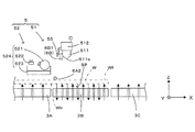
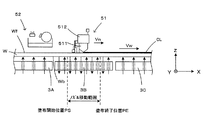
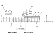
図1Aは本発明にかかる塗布装置の一実施形態を示す図であり、鉛直上方から見た平面図である、また、図1Bは図1Aから塗布機構を取り外した平面図である。また、図2は図1Aに示す塗布装置を制御する制御機構を示すブロック図である。なお、図1A、図1Bおよび後で説明する各図では、装置各部の配置関係を明確にするために、基板Wの搬送方向を「X方向」とし、図1A、図1Bの左手側から右手側に向かう水平方向を「+X方向」と称し、逆方向を「−X方向」と称する。また、X方向と直交する水平方向Yのうち、装置の正面側を「−Y方向」と称するとともに、装置の背面側を「+Y方向」と称する。さらに、鉛直方向Zにおける上方向および下方向をそれぞれ「+Z方向」および「−Z方向」と称する。 FIG. 1A is a view showing an embodiment of a coating apparatus according to the present invention, which is a plan view seen from vertically above, and FIG. 1B is a plan view with the coating mechanism removed from FIG. 1A. FIG. 2 is a block diagram showing a control mechanism for controlling the coating apparatus shown in FIG. 1A. In FIGS. 1A and 1B and in each drawing described later, in order to clarify the arrangement relationship of each part of the apparatus, the transport direction of the substrate W is set to the “X direction” and the right hand from the left hand side in FIGS. 1A and 1B is used. The horizontal direction toward the side is referred to as “+ X direction”, and the opposite direction is referred to as “−X direction”. Further, among the horizontal direction Y orthogonal to the X direction, the front side of the apparatus is referred to as “−Y direction” and the back side of the apparatus is referred to as “+ Y direction”. Further, the upward direction and the downward direction in the vertical direction Z are referred to as “+ Z direction” and “−Z direction”, respectively.
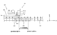
塗布装置1は、コロコンベア100から搬送されてくる水平姿勢の矩形基板Wを受け入れ、当該基板Wの表面Wfに塗布液を塗布するスリットコータである。この塗布装置1では、コロコンベア100に隣接して移載機構2が設けられている。この移載機構2は、コロコンベア100から基板Wを受け取って浮上機構3に移載する。
The
浮上機構3は3つの浮上ユニット3A〜3Cを有している。これらの浮上ユニット3A〜3Cは、図1Bに示すように、基板Wの搬送方向Xに配列されている。より詳しくは、最も上流側、つまり(−X)方向側に上流浮上ユニット3Aが移載機構2に隣接して配置され、最も下流側、つまり(+X)方向側に下流浮上ユニット3Cが配置されている。また、上流浮上ユニット3Aと下流浮上ユニット3Cとの間に中央浮上ユニット3Bが配置されている。
The
図3Aは浮上機構の平面図であり、図3Bは浮上機構と塗布機構との関係を模式的に示す側面図である。なお、これらの図面では、中央浮上ユニット3Bの全部と、上流浮上ユニット3Aおよび下流浮上ユニット3Cの一部分とを模式的に示している。
FIG. 3A is a plan view of the levitation mechanism, and FIG. 3B is a side view schematically showing the relationship between the levitation mechanism and the coating mechanism. In these drawings, all of the
上流浮上ユニット3Aおよび下流浮上ユニット3Cは、ともに多数の空気の噴出孔31が1枚の板状のステージ面32の全面にわたってマトリックス状に分散して形成されている。そして、各噴出孔31に対して圧縮空気が与えられることで、各噴出孔31からの圧縮空気の噴出による気体圧力によって基板Wを浮上させる。これによって、上流浮上ユニット3Aおよび下流浮上ユニット3Cでは、基板Wは上記ステージ面32から所定の浮上高さ、例えば10〜500マイクロメートルだけ浮上する。なお、各噴出孔31に圧縮空気を供給するために、例えば特許文献1に記載の構成を用いることができる。
Both the
また、図3Aおよび図3Bへの図示を省略しているが、下流浮上ユニット3Cは上記噴出孔31以外に複数のリフトピンおよびリフトピン昇降機構を有している。複数のリフトピンは噴出孔31の合間を縫って所定間隔をおいて、基板Wの裏面Wb全体に対向可能に設けられている。そして、リフトピンはステージ面32の下方に設置されたリフトピン昇降機構によって、鉛直方向(Z軸方向)に昇降駆動される。つまり、下降時はリフトピンの先端が下流浮上ユニット3Cのステージ面32よりも(−Z)方向側に下降し、上昇時はリフトピンの先端が基板Wを移載ロボット(図示省略)に受け渡す位置まで上昇する。こうして上昇したリフトピンによって基板Wの下面は支持され、持ち上げられるので、基板Wは下流浮上ユニット3Cのステージ面32から上昇する。これによって、移載ロボットによる基板Wの塗布装置1からのアンローディングが可能となる。
Although not shown in FIGS. 3A and 3B, the
一方、中央浮上ユニット3Bは、次のように構成されて、上流浮上ユニット3Aおよび下流浮上ユニット3Cよりも高い浮上精度を有している。すなわち、中央浮上ユニット3Bは、矩形形状の板状のステージ面33を有している。このステージ面33には、上流浮上ユニット3Aおよび下流浮上ユニット3Cに設けられた噴出孔31よりも狭いピッチで複数の孔がマトリックス状に分散して設けられている。また、上流浮上ユニット3Aおよび下流浮上ユニット3Cと異なり、中央浮上ユニット3Bでは、孔のうち半分は圧縮空気の噴出孔34aとして機能し、残りの半分は吸引孔34bとして機能する。つまり、噴出孔34aから圧縮空気を基板Wの裏面Wbに向けて噴出してステージ面33と基板Wの裏面Wbとの間の空間SP(図3B)に圧縮空気を送り込む。一方、吸引孔34bを介して空間SPから空気を吸引するように構成されている。このように上記空間SPに対して空気の噴出と吸引とが行われることで、上記空間SPでは各噴出孔34aから噴出された圧縮空気の空気流は水平方向に広がった後、当該噴出孔34aに隣接する吸引孔34bから吸引されることになり、上記空間SPに広がる空気層(圧力気体層)における圧力バランスは、より安定的となり、基板Wの浮上高さを高精度に、しかも安定して制御することができる。なお、各噴出孔34aへの圧縮空気の供給および吸引孔34bからの空気の吸引を行うために、例えば特許文献1に記載の構成を用いることができる。
On the other hand, the
また、上記のように噴出孔34aおよび吸引孔34bの配列構造を別の角度から見ると、次のような構造を有していると定義することができる。すなわち、中央浮上ユニット3Bは、基板Wの搬送方向Xに対して直交する水平方向Yに延びる帯状に基板Wの一部を安定して浮上させる2種類の浮上列35a、35bを有している。浮上列35aは、噴出孔34a、吸引孔34b、噴出孔34a、…、吸引孔34bおよび噴出孔34aをこの順序でY方向に配列したものである。一方、浮上列35bは、吸引孔34b、噴出孔34a、吸引孔34b、…、噴出孔34aおよび吸引孔34bをこの順序でY方向に配列したものである。そして、これらの浮上列35a、35bを交互にX方向に配列したものが中央浮上ユニット3Bである。各浮上列35a、35bのY方向サイズは基板WのY方向サイズと同じあるいは若干広いため、Y方向において基板Wを安定して浮上させることができる。これに対し、各浮上列35a、35bのX方向サイズは基板WのX方向サイズに比べて大幅に狭いため、単独でX方向において基板Wを安定して浮上させることは難しい。したがって、X方向において基板Wが安定して浮上される領域は中央浮上ユニット3Bの中央部領域である。そこで、本実施形態では、後で説明するようにスリットノズル511をX方向に移動させる範囲(以下「ノズル移動範囲」という)を中央浮上ユニット3Bの中央部領域に制限している。より詳しくは、図3A中の破線で示すように、(−X)側から数えて2つ目の浮上列35aと(+X)側から数えて2つ目の浮上列35bとに挟まれたノズル移動範囲でスリットノズル511は移動可能となっている。
Further, when the arrangement structure of the ejection holes 34a and the
塗布装置1では、浮上ユニット3A〜3Cにより浮上された状態の基板Wを搬送方向Xに間欠的に搬送するために、搬送機構4が設けられている。以下、図1A、図1Bと図4を参照しつつ搬送機構4の構成について説明する。
In the
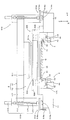
図4は図1Aに示す塗布装置の側面図である。搬送機構4は、浮上機構3により浮上状態で支持されている基板WのY方向の両側端部を吸引して保持しながら浮上機構3により基板Wを浮上させたまま搬送方向Xに搬送する機能を有している。搬送機構4は、図1Bに示すように、基板Wを吸着保持するチャック部41を複数個備えている。ここでは、2つのチャック部材41aをX方向に配列して一体的にX方向に移動自在なチャック部41を、(+Y)方向側および(−Y)方向側にそれぞれ1個、合計2個設けているが、各チャック部材41aをチャック部41として設けてもよい。本実施形態では、上記した2つのチャック部41は、左右対称(+Y側と−Y側とで対称)構造となっており、左右それぞれで、基板Wを吸着保持する。また、搬送機構4は、搬送チャック走行ガイド42と、搬送チャックリニアモータ43と、搬送チャックリニアスケール44と、チャック昇降シリンダ45とを、備えている。チャック部41はチャック昇降シリンダ45の動作により昇降させることが可能となっている。このため、装置全体を制御する制御部9からの保持指令に応じてチャック昇降シリンダ45が作動することで、チャック部41が上昇して(+Y)側、(−Y)側の基板Wの両端部の下面を支持して吸着保持する。また、搬送チャック走行ガイド42は塗布装置1の基台10上でX方向に延設されており、制御部9からの搬送指令に応じて搬送チャックリニアモータ43が作動することで、チャック部41を搬送チャック走行ガイド42に沿って搬送方向Xに往復駆動させる。これによって、チャック部41により保持された基板Wが搬送方向Xに搬送される。なお、本実施形態では、搬送方向Xにおける基板Wの位置を搬送チャックリニアスケール44によって検出可能となっており、制御部9は搬送チャックリニアスケール44の検出結果に基づいて搬送チャックリニアモータ43を駆動制御する。
4 is a side view of the coating apparatus shown in FIG. 1A. The
上記した搬送機構4により基板Wは表面Wfを鉛直上方に向けた、いわゆるフェースアップ状態で搬送方向Xに搬送されるが、当該搬送中に塗布液を基板Wの表面Wfに塗布するために、塗布機構5が設けられている。塗布機構5は、図1Aおよび図2に示すように、基台10に対して搬送方向Xに移動可能なノズルユニット51と、搬送方向Xにおいて当該ノズルユニット51の上流側(図1Aの左手側)で基台10に固定されたノズル洗浄待機ユニット52と、塗布液をノズルユニット51に供給する塗布液供給ユニット58と(図2参照)を有している。
The substrate W is transported in the transport direction X in a so-called face-up state with the surface Wf directed vertically upward by the
ノズルユニット51は、図4に示すように、Y方向に基板Wの表面Wfに対向して延設されたスリットノズル511と、スリットノズル511を支持するノズル支持部材512と、Y方向において搬送機構4よりも外側に設けられた左右対称(+Y側と−Y側とで対称)構造を有する昇降部513とを備えている。この実施形態では、一対の昇降部513でノズル支持部材512を介してスリットノズル511を鉛直方向Zに昇降させて基板Wの表面Wfとの距離、つまり塗布ギャップを調整可能となっている。より詳しくは、各昇降部513は、柱状部材514と、鉛直方向Zに平行に延びた状態で柱状部材514に取り付けられたボールネジ515と、ボールネジ515の上端部に連結された回転モータ516と、ボールネジ515に螺合されたブラケット517とを備えている。そして、制御部9からの回転指令に応じて回転モータ516が作動すると、ボールネジ515が回転し、その回転量に応じてブラケット517が鉛直方向Zに昇降する。このように構成された(+Y)方向側および(−Y)方向側のブラケット517に対してノズル支持部材512の両端部がそれぞれ取り付けられ、ノズル支持部材512を介して昇降可能に支持されている。
As shown in FIG. 4, the
また、各昇降部513は、図4に示すように、塗布機構5の移動機構518によって搬送方向Xに往復移動される。この移動機構518は、図4に示すように、昇降部513を下方から支持するベース部518aと、走行ガイド518bと、リニアモータ518cとを備えている。走行ガイド518bは、図1Aや図1Bに示すように、塗布装置1の基台10上でX方向に延設されており、制御部9からの移動指令に応じてリニアモータ518cが作動することで昇降部513を走行ガイド518bに沿って搬送方向Xに往復移動させ、昇降部513とともにスリットノズル511をメンテナンス位置と吐出位置とに位置決め可能となっている。ここで、「メンテナンス位置」とはノズル洗浄待機ユニット52で予備吐出を含むメンテナンス動作を行う位置を意味し、「吐出位置」とは基板Wに向けて塗布液を吐出する動作を行う位置、つまり中央浮上ユニット3Bの直上位置を意味している。
Further, as shown in FIG. 4, each lifting
また、メンテナンス位置から吐出位置にスリットノズル511を移動させた際には、スリットノズル511は上記ノズル移動範囲の最上流位置(後で説明する塗布開始位置PS)に位置される。また、後述するように塗布処理を行っている間、移動機構518は制御部9のノズル移動指令に応じてスリットノズル511を(+X)方向に移動させ、1枚の基板Wに対する塗布処理の完了と同時に上記ノズル移動範囲の最下流位置(後で説明する塗布終了位置PE)で停止させる。さらに、塗布処理の終了後に、移動機構518は昇降部513と協働してスリットノズル511を吐出位置からメンテナンス位置に移動させる。このように、本実施形態では、スリットノズル511がメンテナンス位置、吐出位置(ノズル移動範囲の塗布開始位置PS)および吐出位置(ノズル移動範囲の塗布終了位置PE)の間を循環的に移動しながら塗布処理が繰り返される。
Further, when the
ノズル支持部材512の下端部にスリットノズル511が吐出口511aを下方に向けた状態で取り付けられている。このため、制御部9による回転モータ516の制御によってスリットノズル511を昇降させて吐出口511aを搬送機構4により搬送される基板Wの表面Wfに近接させたり、逆に上方に離間させることが可能となっている。すなわち、回転モータ516の駆動制御によって塗布ギャップが調整される。
A
また、後述する浮上高さ検出センサ(図3B中の符号53)の出力に基づいて制御部9が回転モータ516を制御しており、これによって基板Wの表面Wfと吐出口511aとの間隔を高精度に調整可能となっている。そして、吐出口511aを基板Wの表面Wfに近接させた状態で塗布液供給ユニット58から塗布液がスリットノズル511に圧送されると、吐出口511aから基板Wの表面Wfに向けて吐出される。なお、スリットノズル511には、ノズル先端を保護するための保護部材(図3B中の符号6B1)、浮上高さ検出センサ(図3B中の符号53)および振動センサ(図3B中の符号6B2)が取り付けられている。
Further, the
ノズル洗浄待機ユニット52は基板Wの表面Wfへの塗布液の供給を行ったスリットノズル511の先端部からレジスト液を洗浄除去する装置であり、当該洗浄処理によってスリットノズル511の吐出口511aは次の塗布処理に適した状態に整えられる。このノズル洗浄待機ユニット52は、図3Bおよび図4に示すように、主にローラ521、洗浄ユニット522、ローラバット523などで構成されてノズル洗浄および予備吐出を行う洗浄待機部524を備えている。この洗浄待機部524では、塗布処理が行われた後のスリットノズル511の吐出口511aの洗浄が行われる。また、ローラ521の外周面にスリットノズル511を近接させた状態で吐出口511aから一定の塗布液を吐出させると、吐出口511aに塗布液の液だまりが形成される(予備吐出動作)。このように吐出口511aに液だまりが均一に形成されると、その後の塗布処理を高精度に行うことが可能となる。このように、スリットノズル511の吐出口511aは初期化され、次の塗布処理に備える。なお、ローラ521の回転は制御部9からの回転指令に応じてローラ回転モータ(図示省略)の駆動により行われる。また、ローラ521に付着した塗布液は、ローラ521が回転する際にローラバット523内に貯留された洗浄液に下端が浸漬されることで、除去される。
The nozzle
上記したように、本実施形態では、スリットノズル511を基板Wの表面Wfに近接させて塗布処理を行うため、表面Wfに異物が存在すると、異物とスリットノズル511との衝突によってスリットノズル511が損傷することがある。また、上記衝突によってスリットノズル511の位置に誤差が生じると、その後における塗布処理を継続することができなくなる。そこで、本実施形態では、基板Wの表面Wfに存在する異物を検出するために、2種類の異物検出機構6A、6Bが設けられている。
As described above, in the present embodiment, since the
異物検出機構6Aは、搬送方向Xにおいて塗布機構に設けられたスリットノズル511の上流側で上記異物を非接触方式で検出するものであり、投光部6A1および受光部6A2を有している。投光部6A1および受光部6A2は、図1Bに示すように、Y方向において中央浮上ユニット3Bを外側から挟み込むように配置されている。投光部6A1および受光部6A2はそれぞれ基台10の上面から鉛直方向Zに立設された支持部材(図示省略)の上端部に取り付けられ、投光部6A1および受光部6A2の高さ位置が調整されている。より具体的には、図3Bに示すように投光部6A1から照射されたレーザ光が基板Wの表面Wf上を通過して受光部6A2に入射されるように、投光部6A1および受光部6A2が配設されている。そして、投光部6A1は受光部6A2に向けてレーザ光を照射する。一方、受光部6A2は投光部6A1から照射されたレーザ光を受光し、その受光量を計測して制御部9に出力する。そして、制御部9は当該受光量に基づいて異物検出を行う。
The foreign
もう一方の異物検出機構6Bは接触方式で上記異物を検出するものであり、本実施形態では、塗布機構5のスリットノズル511に取り付けられている。異物検出機構6Bは、搬送方向Xにおける吐出口511aの上流側でスリットノズル511に取り付けられた保護部材6B1と、スリットノズル511の振動を検出する振動センサ6B2とを有している。保護部材6B1は、スリットノズル511のノズル先端を保護するために水平方向Yに延設されたプレート部材であり、プレート面が基板Wの表面Wfに対して直交するように配置されている。このため、ノズルユニット51の直下位置を基板Wが搬送される際に、基板W上に異物が存在した場合、保護部材6B1は、スリットノズル511のノズル先端と異物との接触によるスリットノズル511の破損を抑制する。また、異物が存在した場合、保護部材6B1が異物と接触して当該保護部材6B1に振動が発生し、スリットノズル511に伝達される。この振動を振動センサ6B2が検出して制御部9に出力する。そして、制御部9は当該振動に基づいて異物検出を行う。なお、スリットノズル511には、上記異物検出機構6B以外に、保護部材6B1よりも先に基板Wの上方領域に進入する位置に、基板Wの浮上高さを非接触で検知するための浮上高さ検出センサ53が設置されている。この浮上高さ検出センサ53によって、浮上した基板Wと、中央浮上ユニット3Bのステージ面33の上面との離間距離を測定することが可能であり、その検出値に伴って、制御部9を介して、スリットノズル511が下降する位置を調整することができる。なお、浮上高さ検出センサ53としては、光学式センサや、超音波式センサなどを用いることができる。
The other foreign
このように、本実施形態では、2種類の異物検出機構6A、6Bを設けることで異物検出を確実に行うことができる。しかも、異物検出時には制御部9は基板Wの搬送を強制的に停止してスリットノズル511の破損や基板Wのダメージなどを未然に防止する。
Thus, in this embodiment, foreign object detection can be reliably performed by providing two types of foreign
制御部9は上記したように塗布装置1の装置各部を制御する機能を有している。この制御部9には、予め定められた処理プログラムを実行して各部の動作を制御するCPU91と、CPU91により実行される処理プログラムや処理中に生成されるデータ等を記憶保存するためのメモリ92と、処理の進行状況や異物検出などを必要に応じてユーザーに報知するための表示部93とが設けられている。そして、塗布装置1では、CPU91が処理プログラムにしたがって装置各部を以下のように制御することで塗布処理が実行される。
As described above, the
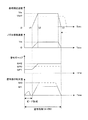
図5は図1Aに示す塗布装置により実行される塗布処理を示すフローチャートである。また、図6は装置各部での動作状況を示すタイミングチャートである。さらに、図7Aないし図7Dは塗布処理中の各段階における各部の位置関係を示す図である。図5に示す塗布処理は、コロコンベア100から未処理の基板Wを受け取った後で、当該基板Wを(+X)方向に浮上搬送しながらスリットノズル511から塗布液を基板Wの表面Wfに吐出して塗布層を形成するものである。この塗布処理は、CPU91が予め記憶された処理プログラムを実行して各部を制御することによりなされる。
FIG. 5 is a flowchart showing a coating process executed by the coating apparatus shown in FIG. 1A. FIG. 6 is a timing chart showing the operating status of each part of the apparatus. Further, FIGS. 7A to 7D are views showing the positional relationship of each part at each stage during the coating process. In the coating process shown in FIG. 5, after receiving an unprocessed substrate W from the
制御部9に対して塗布指令が与えられると、移載機構2がコロコンベア100から基板Wを受け取り、浮上ユニット3Aに移載する(ステップS101)。また、制御部9は塗布指令に含まれる塗布処理に関する各種情報、つまり基板サイズ、基板搬送速度などの塗布条件を取得し、それらに基づいてノズル移動範囲でのスリットノズル511の移動速度(以下「ノズル移動速度」という)の適正値を演算する(ステップS102)。というのも、本実施形態では、後で詳述するように基板Wを(+X)方向に搬送する一方でスリットノズル511を(+X)方向に基板Wの搬送速度(以下「基板搬送速度」という)よりも遅いノズル移動速度でノズル移動範囲内を移動させて基板Wの表面Wfのほぼ全面に塗布液を塗布するからである。つまり、本実施形態では、基板Wとスリットノズル511とを同じ(+X)方向で、しかも基板Wとスリットノズル511との相対速度、つまり塗布速度を基板移動速度よりも抑えながら塗布処理を行うという、従来技術にはないユニークな技術を採用しているからである。なお、このステップS102で設定されたノズル移動速度の詳細については、以下において詳述する。
When a coating command is given to the
次のステップS103では、ノズル洗浄待機ユニット52において、予備吐出を実行する。この予備吐出は、ローラ521の外周面にスリットノズル511を近接させた状態で吐出口511aから一定の塗布液を吐出させる動作であり、これによって、図7Aに示すように、吐出口511aに塗布液の液だまりLDが形成される。このように吐出口511aに液だまりLDが均一に形成されると、その後の塗布処理を高精度に行うことが可能となる。こうして、スリットノズル511の吐出口511aは初期化され、次の塗布処理の準備を完了する。
In the next step S103, preliminary discharge is executed in the nozzle
これに続いて、制御部9からの移動指令に応じて昇降部513および移動機構518が作動してスリットノズル511を塗布開始位置PSに移動させ、吐出口511a(図3B)を鉛直下方に向けて位置決めする(ステップS104)。また、スリットノズル511の移動と同時あるいは前後して、搬送機構4が制御部9からの搬送指令に応じて基板Wを(+X)方向に搬送させ、基板Wの表面Wfのうち最初に塗布すべき領域が塗布開始位置PSに位置した時点で基板搬送を停止する(ステップS105)。こうして、図7Bに示すように、スリットノズル511および基板Wの塗布開始位置PSへの位置決めがともに完了すると、図6および図7Bないし図7Dに示すようにして塗布処理が実行される(ステップS106)。また、塗布処理と並行して移載機構2が次の基板Wをコロコンベア100から受け取り、浮上ユニット3Aに移載し(ステップS107)、次の塗布処理に備える。
Following this, the elevating
塗布処理の開始時点(図6におけるタイミングt1)では、図7Bに示すようにスリットノズル511および基板Wが塗布開始位置PSに位置決めされ、基板搬送速度、ノズル移動速度はともにゼロとなっており、基板Wの表面Wfの直上位置にスリットノズル511が位置している。また、昇降部513によりスリットノズル511が基板Wに近接される。このときの塗布ギャップ(スリットノズル511の吐出口511aと基板Wの表面Wfとの距離)は値GP1であり、こうして吐出口551aを近接させた状態で一定時間(タイミングt1〜t2)の間に制御部9は塗布液供給ユニット58を制御して一定量の塗布液をスリットノズル511に圧送してビードB(基板W上での液溜り)を形成する。
At the start of the coating process (timing t1 in FIG. 6), as shown in FIG. 7B, the
そして、次のタイミングt2で、(+X)方向への基板Wの搬送が開始されるとともに(+X)方向へのスリットノズル511の移動が開始される。また、塗布ギャップが値GP1から値GP2に引き上げられるとともに、塗布液がスリットノズル511に圧送されて吐出口511aから単位時間当たり吐出量M1で基板Wの表面Wfに吐出される。
At the next timing t2, the transport of the substrate W in the (+ X) direction is started and the movement of the
この実施形態では、予めステップS102でノズル移動速度Vnが基板搬送速度Vwよりも遅くなるように設定されており、スリットノズル511に対して基板Wが相対速度V(=Vw−Vn)で(+X)方向に搬送される。このため、図7Cに示すように、時間経過に伴ってスリットノズル511が(+X)方向に移動しながら相対速度Vで基板Wの表面Wfに塗布層CLが形成されていく。つまり、本実施形態では、塗布速度は基板搬送速度Vwよりも遅くなっている。
In this embodiment, the nozzle moving speed Vn is set in advance to be slower than the substrate transport speed Vw in step S102, and the substrate W is at a relative speed V (= Vw−Vn) (+ X with respect to the
そして、タイミングt3に達すると、塗布液の吐出が停止されるとともに、基板Wの搬送およびスリットノズル511の移動がともに停止される。このとき、図7Dに示すように、基板Wの表面Wfのうち最後に塗布すべき領域とスリットノズル511とが塗布終了位置PEに位置し、塗布処理が終了する。このように、本実施形態では、基板Wを比較的速い基板搬送速度Vwで搬送しながらもスリットノズル511を(+X)方向に移動させることで基板搬送速度Vwよりもノズル移動速度Vn分だけ遅い速度で塗布液を基板Wの表面Wfに塗布することが可能となっている。すなわち、上記ステップS102では、当該塗布処理が可能となるように塗布条件に基づいてノズル移動速度Vnを演算している。
When the timing t3 is reached, the discharge of the coating liquid is stopped, and the transport of the substrate W and the movement of the
図5に戻って塗布装置1の動作説明を続ける。上記のようにして塗布処理(ステップS106)が完了すると、スリットノズル511が塗布終了位置PEからノズル洗浄待機ユニット52に向けて移動される(ステップS108)。一方、塗布層CLが塗布された基板Wは次のようにして搬出される(ステップS109)。すなわち、基板Wは下流浮上ユニット3Cまで搬送された後でリフトピン(図示省略)を上昇され、下流浮上ユニット3Cのステージ面32から持ち上げられる。さらに、当該基板Wは移載ロボット(図示省略)により塗布装置1から搬出される。
Returning to FIG. 5, the description of the operation of the
ここで、移載機構2により次の未処理基板Wが浮上ユニット3Aに移載されて待機しているとき(ステップS110で「YES」)には、当該待機中の基板Wに対する塗布条件が前回の塗布条件から変更されるか否かをステップS111で確認した上で上記一連の処理を繰り返す。つまり、塗布条件が変更された場合(ステップS111で「YES」)にはステップS102に戻る一方、変更されていない場合(ステップS111で「NO」)にはステップS103に戻って上記処理を繰り返す。
Here, when the next unprocessed substrate W is transferred to the
以上のように、本実施形態では、基板搬送方向、つまり(+X)方向と同じ方向にスリットノズル511を図6、図7Cおよび図7Dに示すように、基板搬送速度Vwよりも遅いノズル移動速度Vnで移動させながら塗布処理を行っている。このため、基板Wを比較的高速で搬送しているにもかかわらず、塗布装置1での塗布速度(=Vw-Vn)は基板搬送速度Vwよりも遅く、カスレなどの不具合を発生させることなく、タクトタイムを短縮することができる。
As described above, in this embodiment, as shown in FIGS. 6, 7C, and 7D, the nozzle movement speed of the
ここで、上記作用効果を明確にするために、従来技術との対比で上記実施形態のメリットについて図6を参照しつつ説明する。スリットノズル511を固定した従来技術においては、図6の最上段グラフ中の1点鎖線で示すように、上記不具合の発生を防止するためには基板搬送速度を本実施形態での基板搬送速度Vwよりも遅い速度Vw0に設定せざるを得ず、そのためにタクトタイムの長時間化が避けなれない。また、従来技術において基板搬送速度を本実施形態での基板搬送速度Vwと同じ値に設定しながらもカスレ等の不具合が発生するのを防止するためには、図6の上から3番目のグラフ中の1点鎖線で示すように塗布ギャップを本実施形態での塗布ギャップGP2よりも狭い塗布ギャップGP0に設定した状態で基板Wを高速で搬送せざるを得ず、スリットノズル511と基板Wとの接触リスクが高くなるという問題が発生する。さらに、図6の最下段グラフ中の1点鎖線で示すように単位時間当たりの塗布液の吐出量を量M1よりも多い量M0に増やすことでカスレ等の不具合に対応することも考えられるが、塗布液の消費量が増大してしまい、ランニングコストが高くなるという別の問題が発生する。これに対し、本実施形態によれば、上記問題を発生させることなく、塗布処理を安定して短いタクトタイムで実行することができる。また、本実施形態にかかる塗布装置1は、塗布液の使用量を削減することができ、環境保全の面において有効である。
Here, in order to clarify the above-described effects, the advantages of the above-described embodiment will be described with reference to FIG. In the prior art in which the
このように本実施形態では、基板Wの表面Wfが本発明の「基板の主面」に相当している。また、浮上機構3および浮上ユニット3A〜3Cがそれぞれ本発明の「浮上部」、「上流浮上部」、「精密浮上部」および「下流浮上部」の一例に相当している。また、搬送機構4および移動機構518がそれぞれ本発明の「搬送部」および「移動部」の一例に相当している。さらに、(+X)方向が本発明の「搬送方向」に相当している。
Thus, in this embodiment, the surface Wf of the substrate W corresponds to the “main surface of the substrate” of the present invention. Further, the
なお、本発明は上記した実施形態に限定されるものではなく、その趣旨を逸脱しない限りにおいて上述したもの以外に種々の変更を行うことが可能である。例えば上記実施形態では、ノズル移動範囲を図3A中の破線で示すように設定しているが、ノズル移動範囲はこれに限定されるものではなく、さらに内側に設定してもよい。 The present invention is not limited to the above-described embodiment, and various modifications other than those described above can be made without departing from the spirit of the present invention. For example, in the above embodiment, the nozzle movement range is set as indicated by the broken line in FIG. 3A, but the nozzle movement range is not limited to this and may be set further inside.
また、上記実施形態では、塗布条件が変更される毎に、塗布条件に基づいてノズル移動速度を演算している(ステップS102)が、基板W毎に予めノズル移動速度を求めるとともに制御部9に保存しておき、演算工程を行うことなく、基板W毎にノズル移動速度を設定するように構成してもよい。 In the above embodiment, every time the application condition is changed, the nozzle movement speed is calculated based on the application condition (step S102). The nozzle moving speed may be set for each substrate W without saving and performing the calculation process.
本発明は、基板の主面を上方に向けて浮上させた状態で搬送方向に所定の基板搬送速度で搬送しながら前記基板の主面に塗布液を塗布する塗布技術全般に適用することができる。 INDUSTRIAL APPLICABILITY The present invention can be applied to all coating techniques in which a coating liquid is applied to the main surface of the substrate while being transported at a predetermined substrate transport speed in the transport direction in a state where the main surface of the substrate is floated upward. .
1…塗布装置
3…浮上機構(浮上部)
3A…上流浮上ユニット(上流浮上部)
3B…中央浮上ユニット(精密浮上部)
3C…下流浮上ユニット(下流浮上部)
4…搬送機構(搬送部)
9…制御部
511…スリットノズル
511a…吐出口
518…移動機構(移動部)
Vn…ノズル移動速度
Vw…基板搬送速度
W…基板
Wf…表面(基板の主面)
X…搬送方向
1 ...
3A: Upstream levitation unit (upstream levitation unit)
3B ... Center levitation unit (precision levitation)
3C: Downstream levitation unit (downstream levitation unit)
4 ... Conveying mechanism (conveying part)
DESCRIPTION OF
Vn: Nozzle moving speed Vw: Substrate transport speed W ... Substrate Wf ... Front surface (main surface of the substrate)
X: Transport direction
Claims (4)
前記浮上部により浮上させられた前記基板を所定の搬送方向に基板搬送速度で搬送する搬送部と、
前記搬送部によって搬送される前記基板の主面に塗布液を吐出して塗布するノズルと、
前記塗布液を吐出している前記ノズルを前記搬送方向に前記基板搬送速度よりも遅いノズル移動速度で移動させる移動部と、
を備えることを特徴とする塗布装置。 A floating portion for floating the substrate with the main surface of the substrate facing upward;
A transport unit that transports the substrate levitated by the floating part in a predetermined transport direction at a substrate transport speed;
A nozzle for discharging and applying a coating liquid onto the main surface of the substrate conveyed by the conveying unit;
A moving unit that moves the nozzle discharging the coating liquid in the transport direction at a nozzle moving speed slower than the substrate transport speed;
A coating apparatus comprising:
前記浮上部は、精密浮上部と、前記搬送方向の上流側で前記精密浮上部に隣接して設けられる上流浮上部と、前記搬送方向の下流側で前記精密浮上部に隣接して設けられる下流浮上部とを有し、
前記上流浮上部および前記下流浮上部による前記基板の浮上精度は前記精密浮上部による前記基板の浮上精度よりも低く、
前記移動部は、前記ノズルを前記精密浮上部と対向させながら移動させる塗布装置。 The coating apparatus according to claim 1,
The floating part includes a precision floating part, an upstream floating part provided adjacent to the precision floating part on the upstream side in the transport direction, and a downstream provided adjacent to the precision floating part on the downstream side in the transport direction. With a floating part,
The floating accuracy of the substrate by the upstream floating portion and the downstream floating portion is lower than the floating accuracy of the substrate by the precise floating portion,
The said moving part is a coating device which moves the said nozzle facing the said precision floating part.
前記移動部は、前記搬送方向において前記精密浮上部の中央部と対向させながら移動させる塗布装置。 The coating apparatus according to claim 2,
The said moving part is a coating device moved while making it oppose the center part of the said precision floating part in the said conveyance direction.
ノズルから前記基板の主面に前記塗布液を吐出しながら前記ノズルを前記搬送方向に前記基板搬送速度よりも遅いノズル移動速度で移動させることを特徴とする塗布方法。 A coating method for applying a coating liquid to the main surface of the substrate while transporting at a predetermined substrate transport speed in the transport direction in a state where the main surface of the substrate is floated upward,
A coating method, wherein the nozzle is moved in the transport direction at a nozzle moving speed slower than the substrate transport speed while discharging the coating liquid from the nozzle onto the main surface of the substrate.
Priority Applications (2)
| Application Number | Priority Date | Filing Date | Title |
|---|---|---|---|
| JP2016180155A JP2018043200A (en) | 2016-09-15 | 2016-09-15 | Coating applicator and application method |
| CN201710826731.5A CN107824392A (en) | 2016-09-15 | 2017-09-14 | Applying device and coating method |
Applications Claiming Priority (1)
| Application Number | Priority Date | Filing Date | Title |
|---|---|---|---|
| JP2016180155A JP2018043200A (en) | 2016-09-15 | 2016-09-15 | Coating applicator and application method |
Publications (1)
| Publication Number | Publication Date |
|---|---|
| JP2018043200A true JP2018043200A (en) | 2018-03-22 |
Family
ID=61643852
Family Applications (1)
| Application Number | Title | Priority Date | Filing Date |
|---|---|---|---|
| JP2016180155A Pending JP2018043200A (en) | 2016-09-15 | 2016-09-15 | Coating applicator and application method |
Country Status (2)
| Country | Link |
|---|---|
| JP (1) | JP2018043200A (en) |
| CN (1) | CN107824392A (en) |
Cited By (5)
| Publication number | Priority date | Publication date | Assignee | Title |
|---|---|---|---|---|
| CN110676192A (en) * | 2018-07-03 | 2020-01-10 | 株式会社斯库林集团 | Substrate processing apparatus and substrate processing method |
| KR20200097640A (en) * | 2019-02-08 | 2020-08-19 | 가부시키가이샤 스크린 홀딩스 | Coating apparatus and coating method |
| CN111715473A (en) * | 2019-03-19 | 2020-09-29 | 株式会社斯库林集团 | Substrate processing apparatus and substrate processing method |
| CN115739522A (en) * | 2021-09-02 | 2023-03-07 | 株式会社斯库林集团 | Substrate processing apparatus and substrate processing method |
| JP7301385B2 (en) | 2020-10-23 | 2023-07-03 | 株式会社井元製作所 | coating machine |
Citations (8)
| Publication number | Priority date | Publication date | Assignee | Title |
|---|---|---|---|---|
| US20060141130A1 (en) * | 2004-12-28 | 2006-06-29 | Lg Philips Lcd Co., Ltd. | Slit coater having apparatus for supplying a coating solution |
| JP2006253373A (en) * | 2005-03-10 | 2006-09-21 | Tokyo Electron Ltd | Apparatus, method, and program for substrate processing |
| JP2009000665A (en) * | 2007-06-25 | 2009-01-08 | Toppan Printing Co Ltd | Method of coating |
| JP2011086875A (en) * | 2009-10-19 | 2011-04-28 | Tokyo Ohka Kogyo Co Ltd | Coating apparatus |
| KR20110077341A (en) * | 2009-12-30 | 2011-07-07 | 주식회사 케이씨텍 | Substrate coater apparatus |
| JP2012187453A (en) * | 2011-03-09 | 2012-10-04 | Toray Eng Co Ltd | Float coating device and float coating method |
| JP5346643B2 (en) * | 2009-03-27 | 2013-11-20 | 大日本スクリーン製造株式会社 | Substrate coating apparatus and substrate coating method |
| JP2014161836A (en) * | 2013-02-27 | 2014-09-08 | Toray Eng Co Ltd | Coating method and coating device |
Family Cites Families (6)
| Publication number | Priority date | Publication date | Assignee | Title |
|---|---|---|---|---|
| JP2005185998A (en) * | 2003-12-26 | 2005-07-14 | Optrex Corp | Treating liquid coating device and method for the same |
| JP4634265B2 (en) * | 2005-09-27 | 2011-02-16 | 東京エレクトロン株式会社 | Coating method and coating apparatus |
| JP4228025B1 (en) * | 2007-12-21 | 2009-02-25 | 株式会社 ハリーズ | Intermittent application device and intermittent application method |
| JP5437134B2 (en) * | 2010-03-31 | 2014-03-12 | 大日本スクリーン製造株式会社 | Coating device |
| JP2015091569A (en) * | 2013-10-03 | 2015-05-14 | 東京エレクトロン株式会社 | Coating apparatus |
| JP2016013900A (en) * | 2014-07-02 | 2016-01-28 | 東レエンジニアリング株式会社 | Levitation conveyance device |
-
2016
- 2016-09-15 JP JP2016180155A patent/JP2018043200A/en active Pending
-
2017
- 2017-09-14 CN CN201710826731.5A patent/CN107824392A/en active Pending
Patent Citations (8)
| Publication number | Priority date | Publication date | Assignee | Title |
|---|---|---|---|---|
| US20060141130A1 (en) * | 2004-12-28 | 2006-06-29 | Lg Philips Lcd Co., Ltd. | Slit coater having apparatus for supplying a coating solution |
| JP2006253373A (en) * | 2005-03-10 | 2006-09-21 | Tokyo Electron Ltd | Apparatus, method, and program for substrate processing |
| JP2009000665A (en) * | 2007-06-25 | 2009-01-08 | Toppan Printing Co Ltd | Method of coating |
| JP5346643B2 (en) * | 2009-03-27 | 2013-11-20 | 大日本スクリーン製造株式会社 | Substrate coating apparatus and substrate coating method |
| JP2011086875A (en) * | 2009-10-19 | 2011-04-28 | Tokyo Ohka Kogyo Co Ltd | Coating apparatus |
| KR20110077341A (en) * | 2009-12-30 | 2011-07-07 | 주식회사 케이씨텍 | Substrate coater apparatus |
| JP2012187453A (en) * | 2011-03-09 | 2012-10-04 | Toray Eng Co Ltd | Float coating device and float coating method |
| JP2014161836A (en) * | 2013-02-27 | 2014-09-08 | Toray Eng Co Ltd | Coating method and coating device |
Cited By (12)
| Publication number | Priority date | Publication date | Assignee | Title |
|---|---|---|---|---|
| CN110676192A (en) * | 2018-07-03 | 2020-01-10 | 株式会社斯库林集团 | Substrate processing apparatus and substrate processing method |
| KR20200004260A (en) * | 2018-07-03 | 2020-01-13 | 가부시키가이샤 스크린 홀딩스 | Substrate processing apparatus and substrate processing method |
| JP2020006282A (en) * | 2018-07-03 | 2020-01-16 | 株式会社Screenホールディングス | Substrate processing apparatus and substrate processing method |
| KR102525265B1 (en) * | 2018-07-03 | 2023-04-24 | 가부시키가이샤 스크린 홀딩스 | Substrate processing apparatus and substrate processing method |
| KR20200097640A (en) * | 2019-02-08 | 2020-08-19 | 가부시키가이샤 스크린 홀딩스 | Coating apparatus and coating method |
| KR102295753B1 (en) | 2019-02-08 | 2021-08-30 | 가부시키가이샤 스크린 홀딩스 | Coating apparatus and coating method |
| CN111715473A (en) * | 2019-03-19 | 2020-09-29 | 株式会社斯库林集团 | Substrate processing apparatus and substrate processing method |
| CN111715473B (en) * | 2019-03-19 | 2021-12-14 | 株式会社斯库林集团 | Substrate processing apparatus and substrate processing method |
| JP7301385B2 (en) | 2020-10-23 | 2023-07-03 | 株式会社井元製作所 | coating machine |
| CN115739522A (en) * | 2021-09-02 | 2023-03-07 | 株式会社斯库林集团 | Substrate processing apparatus and substrate processing method |
| JP2023036124A (en) * | 2021-09-02 | 2023-03-14 | 株式会社Screenホールディングス | Substrate treatment device and substrate treatment method |
| JP7316331B2 (en) | 2021-09-02 | 2023-07-27 | 株式会社Screenホールディングス | SUBSTRATE PROCESSING APPARATUS AND SUBSTRATE PROCESSING METHOD |
Also Published As
| Publication number | Publication date |
|---|---|
| CN107824392A (en) | 2018-03-23 |
Similar Documents
| Publication | Publication Date | Title |
|---|---|---|
| JP2018043200A (en) | Coating applicator and application method | |
| JP2010232472A (en) | Substrate transfer device and substrate processing apparatus | |
| JP5346643B2 (en) | Substrate coating apparatus and substrate coating method | |
| TWI445578B (en) | Coating device | |
| JP2012199413A (en) | Apparatus and method for forming coating film | |
| JP6725374B2 (en) | Substrate processing apparatus and substrate processing method | |
| CN108325788B (en) | Coating device and coating method | |
| CN108525941B (en) | Coating apparatus and coating method | |
| KR20120116880A (en) | Coating apparatus | |
| JP6860357B2 (en) | Coating device and coating method | |
| JP6831406B2 (en) | Coating device and coating method | |
| JP5303231B2 (en) | Coating device | |
| JP6737649B2 (en) | Coating device and coating method | |
| CN108525942B (en) | Floating amount calculation device, coating device, and coating method | |
| JP6722723B2 (en) | Substrate processing apparatus and substrate processing method | |
| JP5372824B2 (en) | Substrate processing apparatus and substrate processing method | |
| JP6916833B2 (en) | Coating device and coating method | |
| TWI753324B (en) | Substrate transfer device and coating device | |
| CN111715473B (en) | Substrate processing apparatus and substrate processing method | |
| JP5663297B2 (en) | Coating device | |
| KR20230034136A (en) | Substrate processing apparatus and substrate processing method |
Legal Events
| Date | Code | Title | Description |
|---|---|---|---|
| RD04 | Notification of resignation of power of attorney |
Free format text: JAPANESE INTERMEDIATE CODE: A7424 Effective date: 20170725 |
|
| A621 | Written request for application examination |
Free format text: JAPANESE INTERMEDIATE CODE: A621 Effective date: 20190624 |
|
| A977 | Report on retrieval |
Free format text: JAPANESE INTERMEDIATE CODE: A971007 Effective date: 20200626 |
|
| A131 | Notification of reasons for refusal |
Free format text: JAPANESE INTERMEDIATE CODE: A131 Effective date: 20200707 |
|
| A02 | Decision of refusal |
Free format text: JAPANESE INTERMEDIATE CODE: A02 Effective date: 20210202 |