JP2020006282A - Substrate processing apparatus and substrate processing method - Google Patents
Substrate processing apparatus and substrate processing method Download PDFInfo
- Publication number
- JP2020006282A JP2020006282A JP2018126654A JP2018126654A JP2020006282A JP 2020006282 A JP2020006282 A JP 2020006282A JP 2018126654 A JP2018126654 A JP 2018126654A JP 2018126654 A JP2018126654 A JP 2018126654A JP 2020006282 A JP2020006282 A JP 2020006282A
- Authority
- JP
- Japan
- Prior art keywords
- substrate
- floating
- nozzle
- processing apparatus
- measuring device
- Prior art date
- Legal status (The legal status is an assumption and is not a legal conclusion. Google has not performed a legal analysis and makes no representation as to the accuracy of the status listed.)
- Granted
Links
Images


Classifications
-
- H—ELECTRICITY
- H01—ELECTRIC ELEMENTS
- H01L—SEMICONDUCTOR DEVICES NOT COVERED BY CLASS H10
- H01L21/00—Processes or apparatus adapted for the manufacture or treatment of semiconductor or solid state devices or of parts thereof
- H01L21/67—Apparatus specially adapted for handling semiconductor or electric solid state devices during manufacture or treatment thereof; Apparatus specially adapted for handling wafers during manufacture or treatment of semiconductor or electric solid state devices or components ; Apparatus not specifically provided for elsewhere
- H01L21/67005—Apparatus not specifically provided for elsewhere
- H01L21/67011—Apparatus for manufacture or treatment
- H01L21/6715—Apparatus for applying a liquid, a resin, an ink or the like
-
- H—ELECTRICITY
- H01—ELECTRIC ELEMENTS
- H01L—SEMICONDUCTOR DEVICES NOT COVERED BY CLASS H10
- H01L21/00—Processes or apparatus adapted for the manufacture or treatment of semiconductor or solid state devices or of parts thereof
- H01L21/02—Manufacture or treatment of semiconductor devices or of parts thereof
- H01L21/02041—Cleaning
- H01L21/02043—Cleaning before device manufacture, i.e. Begin-Of-Line process
- H01L21/02052—Wet cleaning only
-
- H—ELECTRICITY
- H01—ELECTRIC ELEMENTS
- H01L—SEMICONDUCTOR DEVICES NOT COVERED BY CLASS H10
- H01L21/00—Processes or apparatus adapted for the manufacture or treatment of semiconductor or solid state devices or of parts thereof
- H01L21/67—Apparatus specially adapted for handling semiconductor or electric solid state devices during manufacture or treatment thereof; Apparatus specially adapted for handling wafers during manufacture or treatment of semiconductor or electric solid state devices or components ; Apparatus not specifically provided for elsewhere
- H01L21/67005—Apparatus not specifically provided for elsewhere
- H01L21/67011—Apparatus for manufacture or treatment
- H01L21/67017—Apparatus for fluid treatment
- H01L21/67028—Apparatus for fluid treatment for cleaning followed by drying, rinsing, stripping, blasting or the like
- H01L21/6704—Apparatus for fluid treatment for cleaning followed by drying, rinsing, stripping, blasting or the like for wet cleaning or washing
- H01L21/67051—Apparatus for fluid treatment for cleaning followed by drying, rinsing, stripping, blasting or the like for wet cleaning or washing using mainly spraying means, e.g. nozzles
-
- H—ELECTRICITY
- H01—ELECTRIC ELEMENTS
- H01L—SEMICONDUCTOR DEVICES NOT COVERED BY CLASS H10
- H01L21/00—Processes or apparatus adapted for the manufacture or treatment of semiconductor or solid state devices or of parts thereof
- H01L21/67—Apparatus specially adapted for handling semiconductor or electric solid state devices during manufacture or treatment thereof; Apparatus specially adapted for handling wafers during manufacture or treatment of semiconductor or electric solid state devices or components ; Apparatus not specifically provided for elsewhere
- H01L21/67005—Apparatus not specifically provided for elsewhere
- H01L21/67242—Apparatus for monitoring, sorting or marking
- H01L21/67259—Position monitoring, e.g. misposition detection or presence detection
-
- H—ELECTRICITY
- H01—ELECTRIC ELEMENTS
- H01L—SEMICONDUCTOR DEVICES NOT COVERED BY CLASS H10
- H01L21/00—Processes or apparatus adapted for the manufacture or treatment of semiconductor or solid state devices or of parts thereof
- H01L21/67—Apparatus specially adapted for handling semiconductor or electric solid state devices during manufacture or treatment thereof; Apparatus specially adapted for handling wafers during manufacture or treatment of semiconductor or electric solid state devices or components ; Apparatus not specifically provided for elsewhere
- H01L21/67005—Apparatus not specifically provided for elsewhere
- H01L21/67242—Apparatus for monitoring, sorting or marking
- H01L21/67276—Production flow monitoring, e.g. for increasing throughput
-
- H—ELECTRICITY
- H01—ELECTRIC ELEMENTS
- H01L—SEMICONDUCTOR DEVICES NOT COVERED BY CLASS H10
- H01L21/00—Processes or apparatus adapted for the manufacture or treatment of semiconductor or solid state devices or of parts thereof
- H01L21/67—Apparatus specially adapted for handling semiconductor or electric solid state devices during manufacture or treatment thereof; Apparatus specially adapted for handling wafers during manufacture or treatment of semiconductor or electric solid state devices or components ; Apparatus not specifically provided for elsewhere
- H01L21/677—Apparatus specially adapted for handling semiconductor or electric solid state devices during manufacture or treatment thereof; Apparatus specially adapted for handling wafers during manufacture or treatment of semiconductor or electric solid state devices or components ; Apparatus not specifically provided for elsewhere for conveying, e.g. between different workstations
- H01L21/67703—Apparatus specially adapted for handling semiconductor or electric solid state devices during manufacture or treatment thereof; Apparatus specially adapted for handling wafers during manufacture or treatment of semiconductor or electric solid state devices or components ; Apparatus not specifically provided for elsewhere for conveying, e.g. between different workstations between different workstations
- H01L21/67715—Changing the direction of the conveying path
-
- H—ELECTRICITY
- H01—ELECTRIC ELEMENTS
- H01L—SEMICONDUCTOR DEVICES NOT COVERED BY CLASS H10
- H01L21/00—Processes or apparatus adapted for the manufacture or treatment of semiconductor or solid state devices or of parts thereof
- H01L21/67—Apparatus specially adapted for handling semiconductor or electric solid state devices during manufacture or treatment thereof; Apparatus specially adapted for handling wafers during manufacture or treatment of semiconductor or electric solid state devices or components ; Apparatus not specifically provided for elsewhere
- H01L21/677—Apparatus specially adapted for handling semiconductor or electric solid state devices during manufacture or treatment thereof; Apparatus specially adapted for handling wafers during manufacture or treatment of semiconductor or electric solid state devices or components ; Apparatus not specifically provided for elsewhere for conveying, e.g. between different workstations
- H01L21/67739—Apparatus specially adapted for handling semiconductor or electric solid state devices during manufacture or treatment thereof; Apparatus specially adapted for handling wafers during manufacture or treatment of semiconductor or electric solid state devices or components ; Apparatus not specifically provided for elsewhere for conveying, e.g. between different workstations into and out of processing chamber
- H01L21/67748—Apparatus specially adapted for handling semiconductor or electric solid state devices during manufacture or treatment thereof; Apparatus specially adapted for handling wafers during manufacture or treatment of semiconductor or electric solid state devices or components ; Apparatus not specifically provided for elsewhere for conveying, e.g. between different workstations into and out of processing chamber horizontal transfer of a single workpiece
-
- H—ELECTRICITY
- H01—ELECTRIC ELEMENTS
- H01L—SEMICONDUCTOR DEVICES NOT COVERED BY CLASS H10
- H01L21/00—Processes or apparatus adapted for the manufacture or treatment of semiconductor or solid state devices or of parts thereof
- H01L21/67—Apparatus specially adapted for handling semiconductor or electric solid state devices during manufacture or treatment thereof; Apparatus specially adapted for handling wafers during manufacture or treatment of semiconductor or electric solid state devices or components ; Apparatus not specifically provided for elsewhere
- H01L21/677—Apparatus specially adapted for handling semiconductor or electric solid state devices during manufacture or treatment thereof; Apparatus specially adapted for handling wafers during manufacture or treatment of semiconductor or electric solid state devices or components ; Apparatus not specifically provided for elsewhere for conveying, e.g. between different workstations
- H01L21/67784—Apparatus specially adapted for handling semiconductor or electric solid state devices during manufacture or treatment thereof; Apparatus specially adapted for handling wafers during manufacture or treatment of semiconductor or electric solid state devices or components ; Apparatus not specifically provided for elsewhere for conveying, e.g. between different workstations using air tracks
-
- H—ELECTRICITY
- H01—ELECTRIC ELEMENTS
- H01L—SEMICONDUCTOR DEVICES NOT COVERED BY CLASS H10
- H01L21/00—Processes or apparatus adapted for the manufacture or treatment of semiconductor or solid state devices or of parts thereof
- H01L21/67—Apparatus specially adapted for handling semiconductor or electric solid state devices during manufacture or treatment thereof; Apparatus specially adapted for handling wafers during manufacture or treatment of semiconductor or electric solid state devices or components ; Apparatus not specifically provided for elsewhere
- H01L21/683—Apparatus specially adapted for handling semiconductor or electric solid state devices during manufacture or treatment thereof; Apparatus specially adapted for handling wafers during manufacture or treatment of semiconductor or electric solid state devices or components ; Apparatus not specifically provided for elsewhere for supporting or gripping
- H01L21/687—Apparatus specially adapted for handling semiconductor or electric solid state devices during manufacture or treatment thereof; Apparatus specially adapted for handling wafers during manufacture or treatment of semiconductor or electric solid state devices or components ; Apparatus not specifically provided for elsewhere for supporting or gripping using mechanical means, e.g. chucks, clamps or pinches
- H01L21/68714—Apparatus specially adapted for handling semiconductor or electric solid state devices during manufacture or treatment thereof; Apparatus specially adapted for handling wafers during manufacture or treatment of semiconductor or electric solid state devices or components ; Apparatus not specifically provided for elsewhere for supporting or gripping using mechanical means, e.g. chucks, clamps or pinches the wafers being placed on a susceptor, stage or support
- H01L21/68742—Apparatus specially adapted for handling semiconductor or electric solid state devices during manufacture or treatment thereof; Apparatus specially adapted for handling wafers during manufacture or treatment of semiconductor or electric solid state devices or components ; Apparatus not specifically provided for elsewhere for supporting or gripping using mechanical means, e.g. chucks, clamps or pinches the wafers being placed on a susceptor, stage or support characterised by a lifting arrangement, e.g. lift pins
-
- H—ELECTRICITY
- H01—ELECTRIC ELEMENTS
- H01L—SEMICONDUCTOR DEVICES NOT COVERED BY CLASS H10
- H01L22/00—Testing or measuring during manufacture or treatment; Reliability measurements, i.e. testing of parts without further processing to modify the parts as such; Structural arrangements therefor
- H01L22/20—Sequence of activities consisting of a plurality of measurements, corrections, marking or sorting steps
- H01L22/26—Acting in response to an ongoing measurement without interruption of processing, e.g. endpoint detection, in-situ thickness measurement
Abstract
Description
この発明は、基板処理装置および基板処理方法に関し、特に、浮上力が付与されて搬送される基板への処理液の塗布を好適に行う技術に関する。処理対象となる基板には、例えば、半導体基板、液晶表示装置および有機EL(Electroluminescence)表示装置などのFPD(Flat Panel Display)用基板、光ディスク用基板、磁気ディスク用基板、光磁気ディスク用基板、フォトマスク用基板、セラミック基板、太陽電池用基板が含まれる。 The present invention relates to a substrate processing apparatus and a substrate processing method, and more particularly to a technique for suitably applying a processing liquid to a substrate to which a levitation force is applied and conveyed. The substrate to be processed includes, for example, a semiconductor substrate, a substrate for an FPD (Flat Panel Display) such as a liquid crystal display device and an organic EL (Electroluminescence) display device, a substrate for an optical disk, a substrate for a magnetic disk, a substrate for a magneto-optical disk, Photomask substrates, ceramic substrates, and solar cell substrates are included.
半導体装置や液晶表示装置などの電子部品等の製造工程では、基板の表面に塗布液を塗布する塗布装置が用いられている。このような塗布装置として、基板の裏面にエアを吹き付けて基板を浮上させた状態で当該基板を搬送しながら、当該基板の表面(基板の主面に相当)に対して基板の幅方向に延びるノズルから塗布液を吐出して基板に塗布液を塗布する装置が知られている(例えば、特許文献1)。 2. Description of the Related Art In a manufacturing process of an electronic component such as a semiconductor device or a liquid crystal display device, a coating apparatus that applies a coating liquid to a surface of a substrate is used. In such a coating apparatus, the substrate is conveyed in a state where the substrate is floated by blowing air to the back surface of the substrate, and extends in the width direction of the substrate with respect to the surface of the substrate (corresponding to the main surface of the substrate). 2. Description of the Related Art There is known an apparatus that applies a coating liquid to a substrate by discharging the coating liquid from a nozzle (for example, Patent Document 1).
特許文献1に記載の基板処理装置では、浮上ステージ上で基板を水平姿勢にて浮上させつつ、基板の周縁部を保持して水平方向に走行させることで当該基板を搬送し、基板搬送経路の上方に配置されたスリットノズルから塗布液を吐出させる。
In the substrate processing apparatus described in
特許文献1の基板処理装置では、基板の上方において、基板の浮上高を測定する光学式距離センサが備えられている。基板の浮上高に応じてスリットノズルの高さを調整しつつ塗布液を供給することが可能となっている。
In the substrate processing apparatus of
しかしながら、特許文献1では、光学式距離センサは、スリットノズルに固定されているため、搬送方向に直交する横方向(基板の幅方向)に関して固定された位置でしか基板の浮上高さを測定できない。このため、基板の横方向における浮上高さの分布を得ることができなかった。例えば、浮上ステージの浮上力が不足することなどによって、横方向における基板の浮上高さにばらつきが発生した場合に、処理液の塗布不良が起こる虞があった。
However, in
そこで、本発明は、浮上力が付与されて搬送される基板に処理液を良好に塗布する技術を提供することを目的とする。 Therefore, an object of the present invention is to provide a technique for satisfactorily applying a processing liquid to a substrate to which a levitation force is applied and conveyed.
上記課題を解決するため、第1態様は、第1主面及び第2主面を有する基板を処理する基板処理装置であって、前記第1主面が鉛直方向の上向きの基板に浮上力を付与する浮上機構と、前記浮上力が付与されている前記基板である浮上基板を水平方向である第1方向に移動させる搬送機構と、前記第1方向に直交する水平方向である第2方向に延びる吐出口を有し、前記浮上基板の前記第1主面に向けて処理液を前記吐出口から吐出可能なノズルと、前記浮上基板の鉛直位置を測定する測定器と、前記測定器を前記第2方向に移動させる測定器移動部とを備える。 In order to solve the above-mentioned problem, a first aspect is a substrate processing apparatus for processing a substrate having a first main surface and a second main surface, wherein the first main surface exerts a floating force on a vertically upward substrate. A floating mechanism for applying, a transport mechanism for moving the floating substrate, which is the substrate to which the floating force is applied, in a first direction that is a horizontal direction, and a transfer mechanism that moves the floating substrate in a second direction that is a horizontal direction orthogonal to the first direction. A nozzle that has a discharge port that extends and is capable of discharging the processing liquid from the discharge port toward the first main surface of the floating substrate, a measuring device that measures a vertical position of the floating substrate, and the measuring device A measuring device moving unit configured to move the measuring device in the second direction.
第2態様は、第1態様の基板処理装置であって、前記測定器移動部は、前記測定器を前記第2方向及び前記第1方向の上流側及び下流側に移動させる。 A second aspect is the substrate processing apparatus according to the first aspect, wherein the measuring device moving unit moves the measuring device upstream and downstream in the second direction and the first direction.
第3態様は、第2態様の基板処理装置であって、前記ノズルに対して前記第1方向の上流側の位置であって、少なくとも前記ノズルの前記吐出口の先端部と水平方向に重なる位置に設けられる緩衝部をさらに備える。 A third aspect is the substrate processing apparatus according to the second aspect, wherein the position is an upstream position in the first direction with respect to the nozzle, and at least a position horizontally overlapping at least a tip end of the discharge port of the nozzle. The apparatus further includes a buffer unit provided in the apparatus.
第4態様は、第3態様の基板処理装置であって、前記測定器移動機構は、前記測定器を、前記ノズルからの前記処理液が前記浮上基板に付着する水平位置である付着水平位置における前記浮上基板の鉛直位置を測定可能な位置から、前記ノズルが前記処理液を吐出するときの前記緩衝部の水平位置における前記浮上基板の鉛直位置を測定可能な位置までの間で前記第2方向に移動させる。 A fourth aspect is the substrate processing apparatus according to the third aspect, wherein the measuring device moving mechanism moves the measuring device at an adhesion horizontal position, which is a horizontal position at which the processing liquid from the nozzle adheres to the floating substrate. The second direction between a position at which the vertical position of the floating substrate can be measured and a position at which the vertical position of the floating substrate at a horizontal position of the buffer when the nozzle discharges the processing liquid can be measured. Move to
第5態様は、第1態様から第4態様のいずれか1つの基板処理装置であって、前記第2方向の異なる位置で前記浮上基板の鉛直位置を測定する複数の前記測定器を有する。 A fifth aspect is the substrate processing apparatus according to any one of the first to fourth aspects, including a plurality of the measuring devices for measuring a vertical position of the floating substrate at different positions in the second direction.
第6態様は、第5態様の基板処理装置であって、前記複数の測定器を連結する連結具、をさらに備え、前記測定器移動部は、前記連結具を前記第2方向に移動させる。 A sixth aspect is the substrate processing apparatus according to the fifth aspect, further comprising a connector for connecting the plurality of measuring devices, wherein the measuring device moving unit moves the connecting device in the second direction.
第7態様は、第1態様から第6態様のいずれか1つの基板処理装置であって、前記浮上機構は、水平面を有するステージと、前記水平面に設けられ、前記鉛直方向の上側に向けてエアを噴出する複数の噴出口と、前記水平面に設けられ、前記鉛直方向の上側のエアを吸引する複数の吸引口とを含む。 A seventh aspect is the substrate processing apparatus according to any one of the first aspect to the sixth aspect, wherein the levitation mechanism is provided on a stage having a horizontal surface, and the air is provided on the horizontal surface, and the air is directed upward in the vertical direction. And a plurality of suction ports provided on the horizontal surface for sucking the air on the upper side in the vertical direction.
第8態様は、第1態様から第7態様のいずれか1つの基板処理装置であって、前記測定器移動機構は、前記浮上基板の前記第1方向下流側の端部が前記ステージの前記第1方向下流側の縁部に配された状態で、前記測定器を前記第2方向に移動させる。 An eighth aspect is the substrate processing apparatus according to any one of the first aspect to the seventh aspect, wherein the measuring device moving mechanism is configured such that an end of the floating substrate on the downstream side in the first direction is the second end of the stage. The measuring instrument is moved in the second direction while being arranged at the edge on the downstream side in one direction.
第9態様は、第1主面及び第2主面を有する基板を処理する基板処理方法であって、(a)前記第1主面が鉛直方向の上向きの基板に浮上力を付与する工程と、(b)前記工程(a)によって浮上力が付与されている前記基板である浮上基板を水平方向である第1方向に移動させる工程と、(c)前記浮上基板の鉛直位置を測定する測定器を、前記第1方向に直交する水平方向である第2方向に移動させることにより、前記浮上基板における前記第2方向の複数点における鉛直位置を測定する工程とを含む。 A ninth aspect is a substrate processing method for processing a substrate having a first main surface and a second main surface, wherein (a) applying a levitation force to a vertically upward substrate having the first main surface; (B) moving the levitation substrate, which is the substrate to which levitation force is applied in the step (a), in a first direction that is a horizontal direction, and (c) measuring the vertical position of the levitation substrate. Measuring the vertical positions at a plurality of points in the second direction on the floating substrate by moving the container in a second direction that is a horizontal direction orthogonal to the first direction.
第1態様の基板処理装置によると、測定器を第2方向に移動させることによって、第2方向に沿って鉛直位置を測定できる。このため、基板の第2方向沿う複数点で鉛直位置を測定できる。これにより、第2方向において、浮上機構による、基板の浮上高さ異常を検出できるため、基板に処理液を良好に塗布できる。 According to the substrate processing apparatus of the first aspect, the vertical position can be measured along the second direction by moving the measuring instrument in the second direction. Therefore, the vertical position can be measured at a plurality of points along the second direction on the substrate. Thus, in the second direction, an abnormality in the floating height of the substrate by the floating mechanism can be detected, so that the processing liquid can be favorably applied to the substrate.
第2態様の基板処理装置によると、第1方向及び第2方向に移動させることによって、基板の第1主面の面内の複数点の鉛直位置を測定できる。 According to the substrate processing apparatus of the second aspect, by moving the substrate in the first direction and the second direction, the vertical positions of a plurality of points in the plane of the first main surface of the substrate can be measured.
第3態様の基板処理装置によると、基板上の異物があった場合に、ノズルの吐出口よりも先に緩衝部が当該異物に衝突する。これによって、ノズルの先端部を異物から保護できる。 According to the substrate processing apparatus of the third aspect, when there is foreign matter on the substrate, the buffer unit collides with the foreign matter before the discharge port of the nozzle. Thus, the tip of the nozzle can be protected from foreign matter.
第4態様の基板処理装置によると、ノズルから処理液を吐出する際に緩衝部が配置される水平位置において、基板の鉛直位置を測定できるため、緩衝部の位置における浮上高さの異常を検出できる。したがって、塗布処理の際に、基板が緩衝部に接触することを低減できる。 According to the substrate processing apparatus of the fourth aspect, since the vertical position of the substrate can be measured at the horizontal position where the buffer is disposed when the processing liquid is discharged from the nozzle, the abnormality of the flying height at the position of the buffer is detected. it can. Therefore, the contact of the substrate with the buffer during the coating process can be reduced.
第5態様の基板処理装置によると、同時に複数点で浮上基板の鉛直位置を測定できるため、単一の測定器をY方向に移動させる場合よりも、移動距離を短くできるため、測定時間を短縮できる。 According to the substrate processing apparatus of the fifth aspect, since the vertical position of the floating substrate can be measured at a plurality of points at the same time, the moving distance can be shorter than when a single measuring device is moved in the Y direction, and the measurement time is reduced. it can.
第6態様の基板処理装置によると、複数の測定器を一体に移動させることができる。このため、複数の測定器を独立に移動させる場合に比べて、移動機構の構成を簡易化できる。 According to the substrate processing apparatus of the sixth aspect, a plurality of measuring instruments can be moved integrally. Therefore, the configuration of the moving mechanism can be simplified as compared with a case where a plurality of measuring instruments are moved independently.
第7態様の基板処理装置によると、処理対象の基板にエアを噴出しつつ、かつ、吸引することによって、精密に搬送できる。 According to the substrate processing apparatus of the seventh aspect, it is possible to transport the substrate precisely by ejecting and sucking air to the substrate to be processed.
第8態様の基板処理装置によると、浮上基板の下流側の端部がステージの下流側の縁部に配置されるため、ステージの下流側の端部に設けられている吸引口の詰まりによる、基板の浮上高さの異常を検出できる。 According to the substrate processing apparatus of the eighth aspect, since the downstream end of the floating substrate is disposed at the downstream edge of the stage, the suction port provided at the downstream end of the stage is clogged. An abnormality in the flying height of the substrate can be detected.
第9態様の基板処理方法によると、測定器を第2方向に移動させることによって、第2方向に沿って鉛直位置を測定できる。このため、基板の第2方向沿う複数点で鉛直位置を測定できる。これにより、第2方向において、浮上機構による、基板の浮上高さ異常を検出できるため、基板に処理液を良好に塗布できる。 According to the substrate processing method of the ninth aspect, the vertical position can be measured along the second direction by moving the measuring instrument in the second direction. Therefore, the vertical position can be measured at a plurality of points along the second direction on the substrate. Thus, in the second direction, an abnormality in the floating height of the substrate by the floating mechanism can be detected, so that the processing liquid can be favorably applied to the substrate.
以下、添付の図面を参照しながら、本発明の実施形態について説明する。なお、この実施形態に記載されている構成要素はあくまでも例示であり、本発明の範囲をそれらのみに限定する趣旨のものではない。図面においては、理解容易のため、必要に応じて各部の寸法や数が誇張又は簡略化して図示されている場合がある。 Hereinafter, embodiments of the present invention will be described with reference to the accompanying drawings. Note that the components described in this embodiment are merely examples, and are not intended to limit the scope of the present invention. In the drawings, the dimensions and the numbers of the respective parts may be exaggerated or simplified as necessary for easy understanding.
相対的または絶対的な位置関係を示す表現(例えば「平行」「直交」「中心」「同心」「同軸」等)は、特に断らない限り、その位置関係を厳密に表すのみならず、公差もしくは同程度の機能が得られる範囲で相対的に角度または距離に関して変位された状態も表すものとする。等しい状態であることを示す表現(例えば「同一」「等しい」「均質」「一致」等)は、特に断らない限り、定量的に厳密に等しい状態を表すのみならず、公差もしくは同程度の機能が得られる差が存在する状態も表すものとする。形状を示す表現(例えば、「四角形状」または「円筒形状」等)は、特に断らない限り、幾何学的に厳密にその形状を表すのみならず、同程度の効果が得られる範囲で、例えば凹凸や面取り等を有する形状も表すものとする。「〜の上」とは、特に断らない限り、2つの要素が接している場合のほか、2つの要素が離れている場合も含む。 Expressions indicating relative or absolute positional relationships (for example, “parallel”, “orthogonal”, “center”, “concentric”, “coaxial”, etc.) not only express the positional relationship strictly, but also express tolerance or It also represents a state in which it is relatively displaced with respect to the angle or the distance within a range where the same function can be obtained. Unless otherwise specified, expressions that indicate equal states (eg, “identical,” “equal,” “homogeneous,” “match,” etc.) not only represent strictly equal states quantitatively, but also have tolerances or similar functions. Also represents a state where there is a difference that can be obtained. Unless otherwise specified, expressions indicating shapes (eg, “square shape” or “cylindrical shape”) not only represent the shape strictly geometrically, but also within a range where the same effect can be obtained, for example. A shape having irregularities and chamfers is also represented. Unless otherwise specified, "on" includes a case where two elements are in contact with each other and a case where two elements are distant from each other.
<1.第1実施形態>
図1は、実施形態の基板処理装置の一例である塗布装置1の全体構成を模式的に示す側面図である。図2は、実施形態の塗布装置1を鉛直方向上側から見た概略平面図である。図3は、実施形態の塗布機構6を除いた塗布装置1を示す概略平面図である。図4は、図2に示すA−A線に沿う位置における塗布装置1の概略断面図である。図5は、実施形態の浮上ステージ部3の一部を示す概略平面図である。
<1. First Embodiment>
FIG. 1 is a side view schematically illustrating an entire configuration of a
塗布装置1は、四角形状の基板Wを水平姿勢(基板Wの上面Wf(第1主面)及び下面(第2主面)が水平面(XY平面)に対して平行となる姿勢)で搬送するとともに、当該基板Wの上面Wfに処理液(塗布液)を塗布するスリットコータである。各図において、塗布装置1の各部の位置関係を明確にするため、基板Wが搬送される第1方向D1に平行な方向を「X方向」とし、入力コンベア100から出力コンベア110へ向かう方向を「+X方向」、その逆方向を「−X方向」とする。X方向と直交する水平方向を「Y方向」とし、図1の手前に向かう方向を「−Y方向」、その逆方向を「+Y方向」とする。X方向およびY方向に直交する鉛直方向をZ方向とし、浮上ステージ部3から見て塗布機構6側に向かう上向きを「+Z方向」、その逆方向を「−Z方向」とする。
The
塗布装置1の基本的構成や動作原理は、特開2010−227850号公報、特開2010−240550公報に記載されたものと、部分的に共通または類似する。そこで、本明細書では、塗布装置1の各構成のうちこれらの公知文献に記載の物と同一または技術常識等に基づいて容易に類推できる構成については、適宜省略する場合がある。
The basic configuration and operation principle of the
塗布装置1は、基板Wが搬送される第1方向D1(+X方向)に沿って、順に、入力コンベア100、入力移載部2、浮上ステージ部3、出力移載部4、出力コンベア110を備える。これらは、互いに近接するように配置されており、これらにより、基板Wの搬送経路が形成される。なお、以下の説明において、基板の搬送方向である第1方向D1と関連付けて位置関係を示すとき、「第1方向の上流側」を単に「上流側」と、「第1方向D1の下流側」を「下流側」と略する場合がある。本例では、ある基準位置から見て、−X側が「上流側」であり、+X側が「下流側」である。
The
入力コンベア100は、コロコンベア101と、コロコンベア101を回転駆動する回転駆動機構102とを備える。コロコンベア101の回転により、基板Wは水平姿勢で下流側(+X側)に搬送される。
The
入力移載部2は、コロコンベア21と、コロコンベア21を回転させる回転駆動機構22とを備える。コロコンベア21が回転することで、基板Wは+X方向に搬送される。また、コロコンベア21が昇降することにより、基板Wの鉛直位置が変更される。入力移載部2の動作により、基板Wは、入力コンベア100から浮上ステージ部3に移載される。
The
浮上ステージ部3は、第1方向D1に沿って、3つの平板状のステージを含む。具体的には、浮上ステージ部3は、第1方向D1に沿って順に入口浮上ステージ31、塗布ステージ32、出口浮上ステージ33を備える。これらの各ステージの上面は、同一平面上にある。
The floating
入口浮上ステージ31および出口浮上ステージ33のそれぞれの上面には、浮上制御機構35から供給されるエア(圧縮空気)を噴出する複数の噴出口31h,33hがマトリクス状に設けられている。複数の噴出口31h,33hから噴出される圧縮空気により、基板Wに浮上力が浮力され、基板Wの下面(第2主面)と各ステージ31,33の上面から離間した状態で水平姿勢に支持される。基板Wの下面とステージ31,33の上面との距離は、例えば10−500μm(マイクロメートル)としてもよい。
On the upper surface of each of the
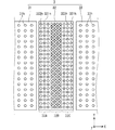
図5に示すように、塗布ステージ32の上面には、エア(圧縮空気)を噴出する複数の噴出口321hと、塗布ステージ32の上方の雰囲気を吸引する複数の吸引口322hとが設けられている。塗布ステージ32の上面では、噴出口321hと吸引口322hとが、X方向及びY方向に沿って交互に設けられている。浮上制御機構35が各噴出口321hからの圧縮空気の噴出量と各吸引口322hからの雰囲気の吸引量とがバランスするように制御することにより、基板Wの下面と塗布ステージ32の上面との距離が精密に制御される。これにより、塗布ステージ32の上方を通過する基板Wの上面Wfの鉛直位置が既定値に制御される。浮上ステージ部3の構成としては、特開2010−227850号公報に記載のものを適用してもよい。
As shown in FIG. 5, on the upper surface of the
塗布ステージ32は、+X方向に向かって順に、上流領域32A、中間領域32B、および、下流領域32Cを有している。ここでは、塗布ステージ32の上面をX方向に1/3ずつ分割することによって得られる3つの領域各々が上流領域32A、中間領域32Bおよび下流領域32Cであり、中間領域32Bが塗布ステージ32の上面の中央を占める領域となっている。
The
上流領域32Aおよび下流領域32C各々よりも中間領域32Bの方において、噴出口321hおよび吸引口322hの分布密度(単位面積あたりの数量)が大きくなっている。このため、中間領域32Bは、上流領域32Aおよび下流領域32C各々よりも、基板Wの浮上量を精密に制御することが可能となっている。
The distribution density (quantity per unit area) of the
中間領域32Bの上方にノズル61の塗布位置L11が設定される。すなわち、中間領域32Bの上方にノズル61の吐出口611が配置された状態で、塗布ステージ32から浮上力が付与された基板W(以下、「浮上基板W」とも称する。)に吐出口611からの処理液が供給される。そして、吐出口611から吐出された処理液が、浮上基板Wに付着するときの水平方向の位置である水平位置も、中間領域32Bの上方とされる。このように、浮上量の精密な制御が可能な中間領域32B上にて浮上基板Wに処理液を供給することによって、塗布処理を良好に行うことができる。
The application position L11 of the
入力移載部2を介して浮上ステージ部3に搬入された基板Wは、コロコンベア21の回転により、+X方向への推進力を得て、入口浮上ステージ31上に搬送される。浮上ステージ部3における基板Wの搬送は、搬送機構5によって行われる。
The substrate W carried into the floating
搬送機構5は、チャック51および吸着・走行制御機構52を備える。チャック51は、基板Wの下面周縁部に部分的に当接することによって基板Wを下方から支持する。吸着・走行制御機構52は、チャック51上端の支持部位に設けられた吸着パッドに負圧を与えて、チャック51に基板Wを吸着保持させる機能を備える。また、吸着・走行制御機構52は、チャック51をX方向に沿って直線状に往復走行させる機能を備える。
The
チャック51が基板Wを保持する状態では、基板Wの下面は、浮上ステージ部3の各ステージ31,32,33の上面よりも+Z側に位置する。基板Wは、チャック51により周縁部を吸着保持され、浮上ステージ部3から付与される浮上力により全体として水平姿勢を維持する。
When the
入力移載部2から浮上ステージ部3に搬入された基板Wをチャック51が保持し、この状態でチャック51が+X方向に移動することにより、基板Wが入口浮上ステージ31の上方から、塗布ステージ32の上方を経由して、出口浮上ステージ33の上方へ搬送される。基板Wは、出口浮上ステージ33の+X側に配置された出力移載部4に渡される。
The
出力移載部4は、コロコンベア41と、当該コロコンベア41を回転駆動する回転駆動機構42とを備える。コロコンベア41が回転することにより、基板Wに+X方向への推進力が付与され、基板Wが第1方向D1に搬送される。出力移載部4の動作により、基板Wは、出口浮上ステージ33の上方から出力コンベア110に移載される。
The
出力コンベア110は、コロコンベア111を回転させる回転駆動機構112を備える。コロコンベア111の回転により、基板Wは+X方向に搬送されて塗布装置1の外部へ払い出される。入力コンベア100および出力コンベア110は、塗布装置1の一部として設けられていてもよいが、塗布装置1とは別体であってもよい。例えば、入力コンベア100は、塗布装置1の上流側に設けられる別ユニットの基板払い出し機構であってもよい。また、出力コンベア110は、塗布装置1の下流側に設けられる別ユニットの基板受け入れ機構であってもよい。
The
基板Wの搬送系路上には、基板Wの上面Wfに処理液を塗布する塗布機構6が設けられている。塗布機構6は、処理液を吐出するノズル61を含むノズルユニット60、ノズル61を位置決めするノズル移動機構63、ノズル61をメンテナンスするメンテナンスユニット65を備える。
An
ノズル61は、第1方向D1に直交する水平方向である第2方向D2(Y方向)に延びる部材である。ノズル61の下端部は、幅方向に延びるとともに下向きに開口する吐出口611を有する。吐出口611からは、処理液が吐出される。
The
ノズル移動機構63は、ノズル61について、X方向およびZ方向に移動させて位置決めする。ノズル移動機構63の動作により、ノズル61は、塗布ステージ32の上方の塗布位置L11に位置決めされる。ノズル61が塗布位置L11に位置決めされた状態で、ノズル61が基板Wの上面Wfに向けて処理液を吐出することにより、基板Wに処理液が塗布される。このように、塗布位置L11は、塗布を実行するときのノズル61の位置である。
The
ノズル61が塗布位置L11に配置された状態で、処理液が基板Wに吐出されることによって、基板Wの上面Wfのうち、周縁部を除く内側の塗布対象領域に、処理液の塗膜が形成される。
When the processing liquid is discharged to the substrate W in a state where the
メンテナンスユニット65は、バット651、予備吐出ローラ652、ノズルクリーナ653およびメンテナンス制御機構654を備える。バット651は、ノズル61の洗浄に使用される洗浄液を貯留する。メンテナンス制御機構654は、予備吐出ローラ652およびノズルクリーナ653を制御する。メンテナンスユニット65の構成として、例えば特開2010−240550号公報に記載された構成を適用してもよい。
The
ノズル移動機構63は、ノズル61を、吐出口611が予備吐出ローラ652の上方にてその表面に対向する予備吐出位置L13に位置決めする。ノズル61hは、予備吐出位置L13にて、吐出口611から予備吐出ローラ652の表面に対して処理液を吐出する(予備吐出処理)。ノズル61は、上述の塗布位置L11に位置決めされる前に予備吐出位置L13に位置決めされて予備吐出処理を実行する。これにより、基板Wへの処理液の吐出を、初期段階から安定させることができる。メンテナンス制御機構654が予備吐出ローラ652を回転させると、ノズル61から吐出された処理液は、バット651に貯留された洗浄液に混合されて回収される。
The
ノズル移動機構63は、ノズル61を、その先端部(吐出口611およびその近くの領域を含む。)がノズルクリーナ653の上方に対向する洗浄位置L14に位置決めする。ノズル61が洗浄位置L14にある状態で、ノズルクリーナ653が洗浄液を吐出しながらノズル61の幅方向(Y方向)に移動することによって、ノズル61の先端部に付着した処理液などが洗い流される。
The
ノズル移動機構63は、ノズル61を、洗浄位置L14よりも下方であって、ノズル61の下端部がバット651内に収容される待機位置に位置決めしてもよい。塗布装置1においてノズル61を用いた塗布処理が実行されないときに、ノズル61が当該待機位置に位置決めされてもよい。図示を省略するが、待機位置に位置決めされたノズル61の吐出口611における処理液の乾燥を防止するための待機ポッドが備えられていてもよい。
The
図1では、予備吐出位置L13にあるノズル61が実線で、塗布位置L11、下流位置L12および洗浄位置L14にあるノズル61が破線でそれぞれ示されている。
In FIG. 1, the
本実施形態の塗布機構6は、1つのノズル61のみを備えているが、複数のノズル61を備えていてもよい。複数のノズル61は、第1方向D1に沿って間隔をあけて備えられていてもよい。この場合において、複数のノズル61に対して異なる処理液を供給することにより、異なる処理液を基板Wに塗布するようにしてもよい。また、各ノズル61に対応するノズル移動機構63及びメンテナンスユニット65をそれぞれ設けてもよい。なお、メンテナンスユニット65は、2つ以上のノズル61が共有して利用できるようにしてもよい。
The
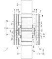
図4に示すように、ノズルユニット60は、浮上ステージ部3の上方でY方向に延びる梁部材631と、当該梁部材631の両側端部を支持する2つの柱部材632,633とを含む架橋構造を有する。柱部材632,633は、基台10から上方に立設されている。柱部材632には昇降機構634が取り付けられており、柱部材633には昇降機構635が取り付けられている。昇降機構634,635は、例えばボールねじ機構を含む。昇降機構634には梁部材631の+Y側端部を、昇降機構635には梁部材631の−Y側端部が取り付けられており、昇降機構634,635によって梁部材631が支持される。制御ユニット9からの制御指令に応じて昇降機構634,635が連動することによって、梁部材631が水平姿勢のまま鉛直方向(Z方向)に移動する。
As shown in FIG. 4, the
図に示すように、梁部材631の中央下部には、Y軸方向に延びるノズル支持体601が設けられている。図7および図8に示すように、ノズル支持体601の下部には、−Y方側から見た形状がL字状である中間部603が取り付けられている。ノズル61は、当該中間部603の水平に延びる部分の下部に、ノズル61が取り付けられている。ノズル61は、吐出口611を下向きにした姿勢でノズル支持体601に取り付けられている。昇降機構634,635が作動することで、ノズル支持体601およびノズル61が鉛直方向(Z方向)に移動する。
As shown in the figure, a
柱部材632,633は、基台10上において移動可能に構成されている。X方向に延びる2つの走行ガイド81L,81Rが、基台10の上面における+Y側端部および−Y側端部に設けられている。柱部材632はその下部に取り付けられたスライダ636を介して+Y側の走行ガイド81Lに係合されており、柱部材633はその下部に取り付けられたスライダ637を介して−Y側の走行ガイド81Rに係合されている。スライダ636,637は、走行ガイド81L,81Rに沿ってX方向に移動自在である。
The
柱部材632,633は、リニアモータ82L,82Rの作動によってX方向に移動する。リニアモータ82L,82Rは、固定子としてのマグネットモジュールと、移動子としてのコイルモジュールとを備える。マグネットモジュールは、基台10に設けられており、X方向に延びている。コイルモジュールは、柱部材632,633のそれぞれの下部に取り付けられている。制御ユニット9からの制御指令に応じてリニアモータ82L,82Rの移動子が作動することによって、ノズルユニット60全体がX方向に沿って移動する。これにより、ノズル61のX方向(第1方向D1)への移動が実現される。柱部材632,633のX方向位置は、スライダ636,637の近傍に設けられたリニアスケール83L,83Rによって検出される。
The
このように、ノズル支持体601およびノズル61は、昇降機構634,635の作動によってZ方向に移動し、リニアモータ82L,82Rの作動によってX方向に移動する。すなわち、制御ユニット9が昇降機構634,635およびリニアモータ82L,82Rを制御することにより、ノズル61の各停止位置L11−L14への位置決めが実現される。したがって、昇降機構634,635およびリニアモータ82L,82Rは、ノズル移動機構63として機能する。
Thus, the
メンテナンスユニット65としては、特開2010−240550号公報に記載のものを採用してもよい。バット651はY方向に延びる梁部材661によって支持される。梁部材661の両端部のうち、一端部は柱部材662で支持され、他端部は柱部材663で支持されている。柱部材662,663は、Y方向に延びるプレート664のY方向両端部にそれぞれ取り付けられている。
As the
プレート664の両端部の下方には、それぞれ、X方向に延びる2つの走行ガイド84L,84Rが設けられている。2つの走行ガイド84L,84Rは、基台10の上面に設けられている。プレート664の下面のY方向両端部のうち、+Y側端部にはスライダ666が設けられ、−Y側端部にはスライダ667が設けられている。スライダ666,667は、走行ガイド84L,84Rに係合して、X方向に移動自在となっている。
Below the both ends of the
プレート664の下方には、リニアモータ85が設けられている。リニアモータ85は、固定子であるマグネットモジュール及び移動子であるコイルモジュールを備える。マグネットモジュールは基台10に設けられており、X方向に延びている。コイルモジュールはメンテナンスユニット65(ここでは、プレート664)の下部に設けられている。
Below the
制御ユニット9からの制御指令に応じてリニアモータ85が作動することにより、メンテナンスユニット65全体がX方向に移動する。メンテナンスユニット65のX方向位置は、スライダ666,667の近傍に設けられたリニアスケール86によって検出される。
When the
図4に示すように、チャック51は、2つのチャック部材51L,51Rを備える。チャック部材51L,51Rは、XZ平面に関して互いに対称な形状を有しており、Y方向に離れて配置されている。
As shown in FIG. 4, the
+Y側に配置されたチャック部材51Lは、基台10に設けられてX方向に延びる走行ガイド87Lに支持される。チャック部材51Lは、X方向に位置を異ならせて設けられた2つの水平なプレート部と、これらのプレート部を接続する接続部とを含むベース部512を備える(図2参照)。ベース部512の2つのプレート部の下部にはスライダ511が1つずつ設けられている。スライダ511は走行ガイド87Lに係合されており、これによってチャック部材51Lは走行ガイド87Lに沿ってX方向に走行可能である。
The
ベース部512の2つのプレート部の上部それぞれには、支持部513が1つずつ設けられている。支持部513は、上方に延びており、その上端部に吸着パッド(不図示)を有する。ベース部512が走行ガイド87Lに沿ってX方向に移動すると、これと一体的に2つの支持部513がX方向に移動する。なお、ベース部512の2つのプレート部位は互いに分離され、これらのプレート部位がX方向に一定の距離を保ちながら移動することで、見かけ上、一体のベース部として機能する構造としてもよい。この距離を基板の長さに応じて設定すれば、種々の長さの基板に対応することが可能となる。
One
チャック部材51Lは、リニアモータ88LによりX方向に移動する。リニアモータ88は、固定子であるマグネットモジュール及び移動子であるコイルモジュールを備える。マグネットモジュールは基台10に設けられており、X方向に延びる。コイルモジュールはチャック部材51Lの下部に設けられている。制御ユニット9からの制御指令に応じてリニアモータ88Lが作動することにより、チャック部材51LがX方向に沿って移動する。チャック部材51LのX方向位置は、走行ガイド87Lの近傍に設けられたリニアスケール89Lによって検出される。
The
−Y側に設けられたチャック部材51Rは、チャック部材51Lと同様に、チャック部材51Rは、ベース部512と、2つの支持部513,513とを備えている。なお、チャック部材51Rの形状は、XZ平面に関してチャック部材51Lとは対称である。チャック部材51Rのベース部512の2つのプレート部の下部にはスライダ511が1つずつ設けられている。スライダ511は走行ガイド87Rに係合されており、これによってチャック部材51Rは走行ガイド87Rに沿ってX方向に走行可能である。
Like the
チャック部材51Rは、リニアモータ88RによってX方向に移動可能である。リニアモータ88Rは、X方向に延びるとともに基台10に設けられた固定子としてのマグネットモジュールと、チャック部材51Rの下部に設けられた移動子としてのコイルモジュールとを含む。制御ユニット9からの制御指令に応じてリニアモータ88Rが作動することにより、チャック部材51RがX方向に移動する。チャック部材51RのX方向位置は、走行ガイド87Rの近傍に設けられたリニアスケール89Rにより検出される。
The
制御ユニット9は、チャック部材51L,51RがX方向において常に同一位置となるように、これらの位置制御を行う。これにより、1対のチャック部材51L,51Rが見かけ上一体のチャック51として移動することになる。チャック部材51L,51Rを機械的に結合する場合に比べ、チャック51と浮上ステージ部3との干渉が容易に回避され得る。
The control unit 9 controls these positions so that the
図3に示すように、4つの支持部513はそれぞれ、保持される基板Wの四隅に対応して配置される。すなわち、チャック部材51Lの2つの支持部513は、基板Wの+Y側周縁部であって第1方向D1における上流側端部と下流側端部とをそれぞれ保持する。チャック部材51Rの2つの支持部513,513は、基板Wの−Y側周縁部であって第1方向D1における上流側端部と下流側端部とをそれぞれ保持する。各支持部513の吸着パッドには必要に応じて負圧が供給され、これにより基板Wの四隅がチャック51により下方から吸着保持される。
As shown in FIG. 3, the four
チャック51が基板Wを保持しながらX方向に移動することで基板Wが搬送される。このように、リニアモータ88L,88R、各支持部513に負圧を供給するための機構(図示せず)は、図1に示す吸着・走行制御機構52として機能する。
The substrate W is transported by the
図1および図4に示すように、チャック51は、入口浮上ステージ31、塗布ステージ32および出口浮上ステージ33の上面よりも上方に離して基板Wを保持する。チャック51は、基板Wの下面を保持して、基板Wを搬送する。チャック51は、基板Wのうち各ステージ31,32,33と対向する中央部分よりもY方向外側の周縁部の一部のみを保持する。このため、基板Wの中央部は周縁部に対し下方に撓む。浮上ステージ部3は、この状態の基板Wの中央部に浮上力を与えることによって、基板Wの鉛直位置を制御し、基板Wを水平姿勢に維持する。
As shown in FIGS. 1 and 4, the
<測定ユニット70>
図6は、ノズル支持体601および測定ユニット70を示す概略平面図である。図7は、ノズル61、測定ユニット70及び緩衝部80を示す概略側面図である。図8は、ノズル61、測定ユニット70及び緩衝部80を示す概略正面図である。
<
FIG. 6 is a schematic plan view showing the
塗布装置1は、測定ユニット70を備えている。測定ユニット70は、複数(ここでは3つ)の測定器72を備えている。各測定器72は、浮上ステージ部3によって浮上力が付与されている基板Wの上面Wfの鉛直位置を測定する。詳細には、測定器72は、既定の鉛直方向の基準位置から、上面Wfの鉛直位置までの距離を測定することによって、上面Wfの鉛直位置を測定する。測定器72によって測定される上面Wfの鉛直位置から、塗布ステージ32の上面の高さ(鉛直位置)から上面Wfの高さを求めることができる。さらに、この上面Wfの高さと基板Wの厚さから、基板Wの浮上量(塗布ステージ32の上面から浮上基板Wの下面までの距離)を求めることが可能である。
The
各測定器72は、所定波長の光を出力する投光部72aと、投光部72aから出力されて基板Wで反射した光を検出する光センサ(例えば、ラインセンサ)を含む受光部72bとを備えている(図9参照)。受光部72bは、上面Wfの鉛直位置を非接触で測定する反射型センサの一例である。なお、上面Wfの鉛直位置は、光で測定される代わりに超音波で測定されてもよい。この場合、各測定器72は、超音波を出力する出力部と、上面Wfで反射した超音波を検出する検出部とを備えているとよい。
Each measuring
測定ユニット70は、3つの測定器72を互いに連結する連結具74を備えている。連結具74は、Y方向に延びる板状の部材であり、連結具74の上流側(−X側)の側面に各測定器72が取り付けられている。ここでは、3つの測定器72は、第2方向(Y方向)に間隔をあけた状態で、連結具74に取り付けられている。
The measuring
測定ユニット70は、測定器移動部76を備えている。測定器移動部76は、連結具74の+X側面に連結されている。測定器移動部76は、リニアモータ機構またはボールネジ機構などの駆動機構を備えている。測定器移動部76は、ノズル支持体601の−X側面の中央部に設けられているY方向に延びるガイドレール部78(図8参照)に沿って、Y方向に移動する。測定器移動部76がY方向に移動すると、連結具74がY方向に移動することによって、3つの測定器72が一体的にY方向(第2方向D2)に移動する。
The
図8に示すように、3つの測定器72がY方向にそれぞれ移動することによって、最も+Y側にある測定器72がY方向における測定範囲RY1にて、Y方向中央にある測定器72がY方向における測定範囲RY2にて、−Y側にある測定器72がY方向における測定範囲RY3にて、浮上基板Wの鉛直位置を測定する。図8に示すように、各測定範囲RY1,RY2,RY3は、Y方向において重なりを有していてもよいが、これは必須ではない。
As shown in FIG. 8, when the three
3つの測定器72は、ノズル61に対して上流側(−X側)に設けられている。各測定器72は、ノズル支持体601に連結されているため、ノズル支持体601に取り付けられたノズル61とともに移動する。すなわち、ノズル61がノズル移動機構63によってX方向およびZ方向に移動すると、各測定器72もノズル61に追従して同一方向に移動する。
The three
<緩衝部80>
図7および図8に示すように、ノズル支持体601の−X側の側面における中央部には、緩衝部80が取り付けられている。緩衝部80は、Y軸方向(第2方向D2)に延びる板状の部材であり、YZ平面に平行に配置されている。緩衝部80は、吐出口611(ノズル61の下端部)と第1方向D1に重なる位置に設けられている。
<Buffer 80>
As shown in FIGS. 7 and 8, a
緩衝部80は、ノズル61よりも搬送方向である第1方向D1の上流側に配置されている。このため、浮上基板Wの上部に吐出口611に接触し得る高さの異物が付着していた場合、当該異物が吐出口611に接触する前に緩衝部80に接触する。これにより、当該異物が緩衝部80に付着して浮上基板Wから除去され、もって、当該異物が吐出口611に接触することを低減できる。なお、異物が緩衝部80に接触したことを検出する当該振動センサを緩衝部80に設けてもよい。そして、当該振動センサが異物の接触を検出した場合に、制御ユニット9が、搬送機構5を制御して、浮上基板Wの搬送を停止させてもよい。
The
図9は、実施形態の制御ユニット9を示す概略ブロック図である。塗布装置1は、各部の動作を制御するための制御ユニット9を備える。制御ユニット9のハードウェア構成は、一般的なコンピュータと同一としてもよい。制御ユニット9は、各種演算処理を行うCPU91、基本プログラムを記憶する読み出し専用のメモリであるROM、各種情報を記憶する読み書き自在のメモリ92、各種情報を表示するディスプレイを含む表示部93を備える。メモリ92としては、主記憶装置(RAM)のほか、制御用アプリケーション(プログラム)およびデータ等を記憶する固定ディスクが含まれる。制御ユニット9は、ユーザーや外部装置との情報交換を担うインターフェース部、および、可搬性を有する記憶媒体(光学式メディア、磁気メディア、半導体メモリなど)に保存された情報(プログラム)を読み取る読取装置を備えていてもよい。
FIG. 9 is a schematic block diagram illustrating the control unit 9 of the embodiment. The
<鉛直位置測定処理>
塗布装置1は、塗布ステージ32による基板Wの鉛直位置の分布を取得する検査(以下、鉛直位置測定処理とも称する。)を行う。上述したように、塗布ステージ32において、吸引口322hは、雰囲気の吸引を行うため、異物を吸引する場合がある。この場合、吸引口322hに詰まりが起こることによって、浮上基板Wの浮上高さが不足するなど、浮上高さに異常が発生する可能性がある。鉛直位置測定処理は、このような浮上高さの異常を検出するために行われる。鉛直位置測定処理は、塗布装置1における基板Wの製造スケジュールに応じて、適宜のタイミングで行われるとよい。例えば、ロットの先頭基板、毎日の先頭基板、毎日午後の先頭基板を塗布処理するタイミングで行われてもよいし、すべての基板Wについて塗布処理するタイミングで行われてもよい。
<Vertical position measurement processing>
The
鉛直位置測定処理は、実際に処理液を塗布する塗布対象である基板Wを用いて行われてもよいが、処理液が塗布されない非塗布対象である基板W(以下、「ダミーの基板W」とも称する。)を用いて行われてもよい。このダミーの基板Wは、上面Wfに配線パターンなどのパターンが形成されていないことが好ましい。基板Wの上面Wfにパターンがある場合、測定器72の投光部72aからの光がパターンで反射して、受光部72bとは異なる方向に向かうことにより、上面Wfからの反射光を検出できない場合がある。そこで、上面Wfにパターンを持たないダミーの基板Wを用いることによって、測定器72が上面Wfからの反射光を良好に検出できる。したがって、鉛直位置の測定を好適に行うことができる。
The vertical position measurement processing may be performed using the substrate W to which the processing liquid is actually applied. However, the substrate W to which the processing liquid is not applied and which is not applied (hereinafter, “dummy substrate W”) May also be used.) It is preferable that a pattern such as a wiring pattern is not formed on the upper surface Wf of the dummy substrate W. When there is a pattern on the upper surface Wf of the substrate W, the light from the
図10は、塗布装置1が実行する鉛直位置測定処理の各工程を示す図である。図10は、上記ダミーの基板Wに対して行われる鉛直位置測定処理の様子を示している。制御ユニット9は、鉛直位置測定処理を開始すると、搬入工程S11を行う。搬入工程S11においては、制御ユニット9が搬送機構5を制御して、浮上ステージ部3から浮上力が付与されている基板(浮上基板)Wを、第1方向D1の下流側(+X方向)に向けて搬送する。
FIG. 10 is a diagram showing each step of the vertical position measurement processing executed by the
搬入工程S11は、停止段階S111を含む。停止段階S111は、図10(b)に示すように、制御ユニット9が搬送機構5を制御して、浮上基板Wを既定位置LW1まで搬送した後、浮上基板Wを既定位置LW1で停止させる段階である。浮上基板Wが既定位置LW1に配置されると、浮上基板Wの下流側端部(先頭端)の水平位置が、塗布ステージ32の下流側端部(縁部)の水平位置と同じか、それよりも僅かに上流側の位置となる。
The loading step S11 includes a stopping step S111. In the stopping step S111, as shown in FIG. 10B, the control unit 9 controls the
制御ユニット9は、停止段階S111の後、測定工程S12を行う。測定工程S12は、Y方向に並ぶ3つの測定器72によって、塗布ステージ32の上方領域32URにおける複数の地点にて浮上基板Wの鉛直位置を測定する工程である。上方領域32URは、少なくとも中間領域32B全体の上方を覆う領域であり、本例では、中間領域32Bよりも上流側の部分(上流領域32Aの一部)及び中間領域32Bよりも下流側の部分(下流領域32Cの一部)の上方を覆う領域である。
After the stopping step S111, the control unit 9 performs the measuring step S12. The measurement step S12 is a step of measuring the vertical position of the floating substrate W at a plurality of points in the upper region 32UR of the
測定工程S12においては、図10(b)に示すように、制御ユニット9は搬送機構5を制御して、3つの測定器72を、既定位置LW1にある浮上基板Wの下流側端部よりも僅かに上流側の水平位置に配置する。これにより、3つの測定器72が下流側端部よりもわずかに上流側の水平位置における浮上基板Wの鉛直位置が測定できる状態となる。この状態で、制御ユニット9は測定器移動部76を制御して3つの測定器72をY方向(第2方向D2)に移動させる。このY方向移動の間、制御ユニット9は、3つの測定器72各々に所定周期で浮上基板Wの鉛直位置を測定させる。これにより、Y方向に延びる一直線上の複数地点における浮上基板Wの鉛直位置が測定される。この3つの測定器72のY方向移動により、ダミーの浮上基板Wの上面Wfにおける、塗布対象領域に相当する領域だけでなく、その領域から+Y側および−Y側にはみ出た部分においても、浮上基板Wの鉛直位置が測定されてもよい。
In the measurement step S12, as shown in FIG. 10B, the control unit 9 controls the
制御ユニット9は、3つの測定器72のY方向移動を完了すると、ノズル移動機構63を制御して、測定ユニット70を、第1方向D1の上流側(−X側)に向けて移動させる(X方向移動)。このときの3つの測定器72の移動量は、塗布ステージ32のX方向の寸法、より好ましくは中間領域32BのX方向の寸法よりも小さい距離である1ピッチ分だけ移動させる。そして、制御ユニット9は、再び3つの測定器72をY方向移動へ移動させつつ、3つの測定器72各々にY方向の複数地点における浮上基板Wの鉛直位置を測定させる。
When the control unit 9 completes the movement of the three
このように、制御ユニット9は、3つの測定器72のX方向移動およびY方向移動を交互に行うことによって、3つの測定器72をY方向およびX方向にジグザグ状に移動させる。これにより、制御ユニット9は、図10(c)に示すように、塗布ステージ32の上方領域32URの複数地点における浮上基板Wの鉛直位置を測定する。この測定工程S12によって、制御ユニット9は、塗布ステージ32の上方領域32URにおける、浮上基板Wの鉛直位置の分布を取得する。
As described above, the control unit 9 alternately moves the three
測定工程S12の後、または、測定工程S12の最中に、測定された各鉛直位置が正常か否かを制御ユニット9が判定してもよい。この判定は、測定値としきい値とを比較して行うとよい。鉛直位置が異常であると判定された場合、制御ユニット9が所定の出力手段(表示部93やランプ、スピーカーなど)でその旨を外部に通知してもよい。また、鉛直位置が異常であると判定された場合、制御ユニット9が塗布装置1の動作を停止させてもよい。
After the measuring step S12 or during the measuring step S12, the control unit 9 may determine whether or not each measured vertical position is normal. This determination may be made by comparing the measured value with a threshold. When it is determined that the vertical position is abnormal, the control unit 9 may notify the outside by a predetermined output unit (the
制御ユニット9は、測定工程S12を完了すると、制御ユニット9は搬出工程S13を行う。測定工程S12で用いられる基板Wは、非塗布対象であるダミーの基板Wである。このため、搬出工程S13は、図10(d)に示すように、制御ユニット9が搬送機構5を制御して、浮上基板Wを下流側に移動させる。これにより、浮上基板Wが塗布ステージ32上から下流側へ搬出される。これにより、塗布対象となる次の基板Wが、塗布ステージ32へ搬入することが可能となる。
When the control unit 9 completes the measurement step S12, the control unit 9 performs an unloading step S13. The substrate W used in the measurement step S12 is a dummy substrate W to be uncoated. Therefore, in the unloading step S13, as shown in FIG. 10D, the control unit 9 controls the
図10に示す鉛直位置測定処理は、塗布対象の基板Wを用いて行われてもよい。この場合、図10(c)に示す測定工程S12の後、制御ユニット9が移動機構63を制御して、ノズル61を塗布位置L11に移動させる。塗布位置L11は、ノズル61から吐出されて浮上基板Wに付着するときの処理液の水平位置が中間領域32Bの内側となるときの、ノズル61の位置である。また、制御ユニット9が浮上基板Wを上流側に移動させて、浮上基板Wが塗布を開始するときの位置に移動させる。ノズル61および浮上基板Wの移動が完了すると、制御ユニット9は、塗布機構6を制御してノズル61から処理液を吐出するとともに、搬送機構5を制御して浮上基板Wを下流側へ移動させる。これにより、塗布ステージ32の中間領域32B上において、浮上基板Wの塗布対象領域に処理液が塗布される。
The vertical position measurement processing shown in FIG. 10 may be performed using the substrate W to be coated. In this case, after the measurement step S12 shown in FIG. 10C, the control unit 9 controls the moving
本実施形態においは、測定器72をY方向(第2方向D2)に移動させることによって、Y方向の複数地点の鉛直位置を測定できる。これにより、Y方向における浮上基板Wの鉛直位置の分布を取得できるため、浮上基板Wの浮上高さの異常を良好に検出できる。測定器72をX方向(第1方向D1)にも移動させることによって、塗布ステージ32の上方領域32URにおける浮上基板Wの鉛直位置の分布を取得できる。これによって、塗布に影響する可能性がある領域における、浮上基板Wの浮上高さの異常を良好に検出できる。これにより、塗布処理を好適に実施することができる。
In the present embodiment, the vertical positions of a plurality of points in the Y direction can be measured by moving the measuring
また、図10(b)に示すように、浮上基板Wの下流側端部が塗布ステージ32の下流側端部(縁部)に配置される。これにより、浮上基板Wに対しては、塗布ステージ32よりも上流側にある出口浮上ステージ33からの浮上力の影響をほとんど受けにくい。このため、塗布ステージ32の下流側端部に設けられた吸引口322hの詰まりによる、浮上基板Wの浮上高さの異常を検出することができる。
Further, as shown in FIG. 10B, the downstream end of the floating substrate W is disposed at the downstream end (edge) of the
図11は、塗布装置1が実行する鉛直位置測定処理の各工程を示す図である。図11は、塗布対象の浮上基板Wに対して行われる鉛直位置測定処理の様子を示している。制御ユニット9は、鉛直位置測定処理を開始すると、図11(a)に示すように、搬入工程S11を行う。搬入工程S11は、図10(a)に示す搬入工程と同じである。
FIG. 11 is a diagram showing each step of the vertical position measurement processing executed by the
搬入工程S11は、停止段階S111aを含む。停止段階S111aは、図11(b)に示すように、制御ユニット9が搬送機構5を制御して、浮上基板Wを既定位置LW2まで搬送した後、浮上基板Wを既定位置LW2で停止させる段階である。浮上基板Wが既定位置LW2に配置されると、浮上基板Wの下流側端部の水平位置が、下流領域32Cの上方に配置される。なお、このときの下流側端部の水平位置は、塗布ステージ32の中間領域32Bの上方としてもよいし、中間領域32Bと下流領域32Cの境界上としてもよい。
The loading step S11 includes a stop step S111a. In the stopping step S111a, as shown in FIG. 11B, the control unit 9 controls the
制御ユニット9は、停止段階S111aの後、測定工程S12aを行う。測定工程S12aは、測定工程S12と同様に、Y方向に並ぶ3つの測定器72によって、塗布ステージ32の上方領域321URにおける複数の地点にて浮上基板Wの鉛直位置を測定する工程である。上方領域321URは、処理液の塗布が行われる中間領域32B、および、中間領域32Bよりも上流側の部分(上流領域32Aの一部)の上方を覆う領域である。
After the stop step S111a, the control unit 9 performs the measurement step S12a. The measurement step S12a is a step of measuring the vertical position of the floating substrate W at a plurality of points in the upper region 321UR of the
測定工程S12aにおいては、図11(b)に示すように、制御ユニット9は搬送機構5を制御して、3つの測定器72を既定位置LW2にある浮上基板Wの下流側端部よりもわずかに上流側の水平位置に配置する。これにより、3つの測定器72が下流側端部よりもわずかに上流側の水平位置における浮上基板Wの鉛直位置が測定できる状態となる。この状態で、制御ユニット9は測定器移動部76を制御して3つの測定器72をY方向(第2方向D2)に移動させる。
In the measurement step S12a, as shown in FIG. 11B, the control unit 9 controls the
このY方向移動の間、制御ユニット9は、3つの測定器72各々に所定周期で浮上基板Wの鉛直位置を測定させる。これにより、Y方向に延びる一直線上の複数地点における浮上基板Wの鉛直位置が測定される。
During the movement in the Y direction, the control unit 9 causes each of the three
制御ユニット9は、3つの測定器72のY方向移動を完了すると、移動機構63を制御して、測定ユニット70を、第1方向D1の上流側(−X側)に向けて移動させる(X方向移動)。このときの3つの測定器72の移動量は、塗布ステージ32のX方向の寸法、より好ましくは中間領域32BのX方向の寸法よりも小さい距離である1ピッチ分だけ移動させる。そして、制御ユニット9は、再び3つの測定器72をY方向移動へ移動させつつ、3つの測定器72各々にY方向の複数地点における浮上基板Wの鉛直位置を測定させる。
When the movement of the three
このように、制御ユニット9は、3つの測定器72のX方向移動およびY方向移動を交互に行うことによって、3つの測定器72をY方向およびX方向にジグザグ状に移動させる。これにより、制御ユニット9は、図11(c)に示すように、塗布ステージ32の上方領域321URの複数地点における浮上基板Wの鉛直位置を測定する。この測定工程S12aによって、制御ユニット9は、塗布ステージ32の上方領域321URにおける、浮上基板Wの鉛直位置の分布を取得する。
As described above, the control unit 9 alternately moves the three
測定工程S12aの後、または、測定工程S12aの最中に、測定された各鉛直位置が正常か否かを制御ユニット9が判定してもよい。この判定は、測定値としきい値とを比較して行うとよい。鉛直位置が異常であると判定された場合、制御ユニット9が所定の出力手段(表示部93やランプ、スピーカーなど)でその旨を外部に通知してもよい。また、鉛直位置が異常であると判定された場合、制御ユニット9が塗布装置1の動作を停止させてもよい。
After the measuring step S12a or during the measuring step S12a, the control unit 9 may determine whether or not each measured vertical position is normal. This determination may be made by comparing the measured value with a threshold. When it is determined that the vertical position is abnormal, the control unit 9 may notify the outside by a predetermined output unit (the
制御ユニット9は、測定工程S12aを完了すると、塗布工程S14を行う。塗布工程S14においては、制御ユニット9は、移動機構63を制御してノズル61を塗布位置L11に移動させる。なお、測定工程S12aの完了時点において、ノズル61が塗布位置L11にくるように、各測定器72のX方向移動、あるいは、ノズル61と測定器72の間の距離の設定が行われてもよい。この場合、測定工程S12aの後、塗布工程S14に移行する際におけるノズル61の移動を省略できる。また、制御ユニット9は、搬送機構5を制御して、塗布位置L11のノズル61から処理液が塗布対象領域の上流側端部に供給される既定の供給開始位置に浮上基板Wを移動させる。なお、既定位置LW2がこの供給開始位置に一致する場合、浮上基板Wの移動を省略できる。ノズル61及び浮上基板Wの移動が完了すると、制御ユニット9は、塗布機構6を制御してノズル61から処理液を吐出するとともに、搬送機構5を制御して浮上基板Wを下流側へ移動させる。これにより、塗布ステージ32の中間領域32B上において、浮上基板Wの塗布対象領域に処理液が塗布される。
After completing the measurement step S12a, the control unit 9 performs an application step S14. In the application step S14, the control unit 9 controls the moving
図11に示す鉛直位置測定処理によると、塗布ステージ32のうち、塗布処理が行われる中間領域32Bにおいて、Y方向における浮上基板Wの鉛直位置の分布を取得できる。これにより、Y方向について、浮上基板Wに浮上量の異常がある箇所を良好に特定できるため、塗布不良の発生を低減できる。また、鉛直位置の分布を取得する上方領域321URが、塗布ステージ32のほぼ全面に対応する上方領域32URよりも小さいため、測定時間を短縮できる。
According to the vertical position measurement processing shown in FIG. 11, the distribution of the vertical position of the floating substrate W in the Y direction can be acquired in the
図11に示す例では、各測定器72は、測定工程S12aにおいて、測定位置ML1から測定位置ML2を含む範囲を移動する。ノズル61からの処理液が浮上基板Wに付着する水平位置における浮上基板Wの鉛直位置が測定可能なときの、各測定器72の水平位置である。また、測定位置ML2は、ノズル61が処理液を吐出するとき(すなわち、ノズル61が塗布位置L11に配置されているとき)の緩衝部80の水平位置における浮上基板Wの鉛直位置が測定可能なときの、各測定器72の水平位置である。測定位置ML2に各測定器72を配置することにより、ノズル61が塗布位置L11に配されたときの緩衝部80の水平位置における浮上基板Wの鉛直位置を測定できるため、緩衝部80の水平位置における浮上高さの異常を検出できる。したがって、塗布処理の際に、浮上基板Wが緩衝部80に接触することを低減できる。
In the example illustrated in FIG. 11, each measuring
<2.変形例>
以上、実施形態について説明してきたが、本発明は上記のようなものに限定されるものではなく、様々な変形が可能である。
<2. Modification>
Although the embodiments have been described above, the present invention is not limited to the above-described embodiments, and various modifications are possible.
測定ユニット70が、3つの測定器72を備えることは必須ではない。例えば、測定ユニット70は、2つあるいは4つ以上の測定器72を備えていてもよい。また、測定ユニット70は、単一の測定器72を備えていてもよい。ただし、複数の測定器72をY方向に間隔をあけて配置することによって、Y方向に異なる複数の位置で浮上基板Wの鉛直位置を測定できる。これにより、単一の測定器72を設ける場合よりも、各測定器72の移動距離を短縮できるため、測定時間を短縮できる。
It is not essential that the
測定器移動部76が3つの測定器72を一体的にY方向に移動させることは必須ではない。例えば、3つの測定器72をそれぞれ個別にY方向に移動させる測定器移動機構が設けられてもよい。ただし、複数の測定器72を一体に移動させることによって、測定器72を移動させる構成を簡略化できる。
It is not essential that the measuring
測定ユニット70を、移動機構63によってノズル61と一体にX方向へ移動させることは必須ではない。例えば、測定ユニット70を、ノズル61から独立して、X方向に移動させる測定器移動機構が設けられてもよい。ただし、複数の測定器72をノズル61と一体に移動させることによって、測定器72を移動させる構成を簡略化できる。
It is not essential that the measuring
測定ユニット70が、X方向に一定の間隔をあけて2つ以上の測定器72を備えていてもよい。この場合、各測定器72のY方向移動によって、2つの直線上における浮上基板Wの鉛直位置を同時に測定できる。
The
測定ユニット70をノズル支持体601に対して取り付けるのではなく、他の架橋構造体を別に設けて、この架橋構造体に測定ユニット70を取り付けてもよい。また、メンテナンスユニット65は架橋構造体であるので、メンテナンスユニット65のバット651に対してY方向及びX方向に移動自在に測定ユニット70を取り付けてもよい。この場合において、駆動部を設けることなく、測定ユニット70を手動で移動させる構成としてもよい。
Instead of attaching the
この発明は詳細に説明されたが、上記の説明は、すべての局面において、例示であって、この発明がそれに限定されるものではない。例示されていない無数の変形例が、この発明の範囲から外れることなく想定され得るものと解される。上記各実施形態及び各変形例で説明した各構成は、相互に矛盾しない限り適宜組み合わせたり、省略したりすることができる。 Although the present invention has been described in detail, the above description is illustrative in all aspects and the present invention is not limited thereto. It is understood that innumerable modifications that are not illustrated can be assumed without departing from the scope of the present invention. Each configuration described in each of the above embodiments and modifications can be appropriately combined or omitted as long as they do not contradict each other.
1 塗布装置
3 浮上ステージ部(浮上機構)
31 入口浮上ステージ
32 塗布ステージ
321h 噴出口
322h 吸引口
33 出口浮上ステージ
5 搬送機構
6 塗布機構
601 ノズル支持体
61 ノズル
611 吐出口
63 ノズル移動機構
70 測定ユニット
72 測定器
72a 投光部
72b 受光部
74 連結具
76 測定器移動部
80 緩衝部
9 制御ユニット
D1 第1方向
D2 第2方向
L11 塗布位置
L13 予備吐出位置
L14 洗浄位置
ML1,ML2 位置
S11 搬入工程
S12,S12a 測定工程
S13 搬出工程
S14 塗布工程
W 基板、浮上基板
Wf 上面(第1主面)
DESCRIPTION OF
31
Claims (9)
前記第1主面が鉛直方向の上向きの基板に浮上力を付与する浮上機構と、
前記浮上力が付与されている前記基板である浮上基板を水平方向である第1方向に移動させる搬送機構と、
前記第1方向に直交する水平方向である第2方向に延びる吐出口を有し、前記浮上基板の前記第1主面に向けて処理液を前記吐出口から吐出可能なノズルと、
前記浮上基板の鉛直位置を測定する測定器と、
前記測定器を前記第2方向に移動させる測定器移動部と、
を備える、基板処理装置。 A substrate processing apparatus for processing a substrate having a first main surface and a second main surface,
A levitation mechanism in which the first main surface applies a levitation force to a vertically upward substrate;
A transport mechanism for moving the floating substrate, which is the substrate to which the floating force is applied, in a first direction that is a horizontal direction;
A nozzle having a discharge port extending in a second direction that is a horizontal direction perpendicular to the first direction, and capable of discharging a processing liquid from the discharge port toward the first main surface of the floating substrate;
A measuring device for measuring the vertical position of the floating substrate,
A measuring device moving unit that moves the measuring device in the second direction;
A substrate processing apparatus comprising:
前記測定器移動部は、前記測定器を前記第2方向及び前記第1方向の上流側及び下流側に移動させる、基板処理装置。 The substrate processing apparatus according to claim 1,
The substrate processing apparatus, wherein the measuring device moving unit moves the measuring device upstream and downstream in the second direction and the first direction.
前記ノズルに対して前記第1方向の上流側の位置であって、少なくとも前記ノズルの前記吐出口の先端部と水平方向に重なる位置に設けられる緩衝部、
をさらに備える、基板処理装置。 The substrate processing apparatus according to claim 2, wherein
A buffer portion provided at a position on the upstream side in the first direction with respect to the nozzle, at least at a position horizontally overlapping with a tip end portion of the discharge port of the nozzle;
A substrate processing apparatus, further comprising:
前記測定器移動機構は、前記測定器を、前記ノズルからの前記処理液が前記浮上基板に付着する水平位置である付着水平位置における前記浮上基板の鉛直位置を測定可能な位置から、前記ノズルが前記処理液を吐出するときの前記緩衝部の水平位置における前記浮上基板の鉛直位置を測定可能な位置までの間で前記第2方向に移動させる、基板処理装置。 The substrate processing apparatus according to claim 3, wherein
The measuring device moving mechanism, the measuring device, from the position at which the vertical position of the floating substrate can be measured at the adhesion horizontal position where the processing liquid from the nozzle is attached to the floating substrate, A substrate processing apparatus, wherein the vertical position of the floating substrate at a horizontal position of the buffering unit when discharging the processing liquid is moved in the second direction to a position where the vertical position can be measured.
前記第2方向の異なる位置で前記浮上基板の鉛直位置を測定する複数の前記測定器を有する、基板処理装置。 The substrate processing apparatus according to any one of claims 1 to 4, wherein
A substrate processing apparatus, comprising: a plurality of measuring devices for measuring a vertical position of the floating substrate at different positions in the second direction.
前記複数の測定器を連結する連結具、
をさらに備え、
前記測定器移動部は、前記連結具を前記第2方向に移動させる、基板処理装置。 The substrate processing apparatus according to claim 5, wherein
A connector for connecting the plurality of measuring instruments,
Further comprising
The substrate processing apparatus, wherein the measuring device moving unit moves the connecting tool in the second direction.
前記浮上機構は、
水平面を有するステージと、
前記水平面に設けられ、前記鉛直方向の上側に向けてエアを噴出する複数の噴出口と、
前記水平面に設けられ、前記鉛直方向の上側のエアを吸引する複数の吸引口と、
を含む、基板処理装置。 The substrate processing apparatus according to any one of claims 1 to 6, wherein
The levitation mechanism,
A stage having a horizontal surface,
A plurality of ejection ports that are provided on the horizontal plane and eject air toward the upper side in the vertical direction,
A plurality of suction ports provided on the horizontal surface, for suctioning the air on the upper side in the vertical direction,
And a substrate processing apparatus.
前記測定器移動機構は、前記浮上基板の前記第1方向下流側の端部が前記ステージの前記第1方向下流側の縁部に配された状態で、前記測定器を前記第2方向に移動させる、基板処理装置。 The substrate processing apparatus according to claim 1, wherein:
The measuring device moving mechanism moves the measuring device in the second direction in a state where an end of the floating substrate on the downstream side in the first direction is arranged on an edge of the stage on the downstream side in the first direction. Substrate processing equipment.
(a)前記第1主面が鉛直方向の上向きの基板に浮上力を付与する工程と、
(b)前記工程(a)によって浮上力が付与されている前記基板である浮上基板を水平方向である第1方向に移動させる工程と、
(c)前記浮上基板の鉛直位置を測定する測定器を、前記第1方向に直交する水平方向である第2方向に移動させることにより、前記浮上基板における前記第2方向の複数点における鉛直位置を測定する工程と、
を含む、基板処理方法。 A substrate processing method for processing a substrate having a first main surface and a second main surface,
(A) applying a levitation force to a substrate whose first main surface is vertically upward;
(B) moving the levitation substrate, which is the substrate to which the levitation force has been applied in the step (a), in a first direction that is a horizontal direction;
(C) moving a measuring device for measuring the vertical position of the floating substrate in a second direction, which is a horizontal direction orthogonal to the first direction, so that the vertical positions at a plurality of points in the second direction on the floating substrate. Measuring the
And a substrate processing method.
Priority Applications (4)
| Application Number | Priority Date | Filing Date | Title |
|---|---|---|---|
| JP2018126654A JP6722723B2 (en) | 2018-07-03 | 2018-07-03 | Substrate processing apparatus and substrate processing method |
| TW108120913A TWI760621B (en) | 2018-07-03 | 2019-06-17 | Substrate processing apparatus and substrate processing method |
| KR1020190078889A KR102525265B1 (en) | 2018-07-03 | 2019-07-01 | Substrate processing apparatus and substrate processing method |
| CN201910595463.XA CN110676192A (en) | 2018-07-03 | 2019-07-03 | Substrate processing apparatus and substrate processing method |
Applications Claiming Priority (1)
| Application Number | Priority Date | Filing Date | Title |
|---|---|---|---|
| JP2018126654A JP6722723B2 (en) | 2018-07-03 | 2018-07-03 | Substrate processing apparatus and substrate processing method |
Publications (2)
| Publication Number | Publication Date |
|---|---|
| JP2020006282A true JP2020006282A (en) | 2020-01-16 |
| JP6722723B2 JP6722723B2 (en) | 2020-07-15 |
Family
ID=69068874
Family Applications (1)
| Application Number | Title | Priority Date | Filing Date |
|---|---|---|---|
| JP2018126654A Active JP6722723B2 (en) | 2018-07-03 | 2018-07-03 | Substrate processing apparatus and substrate processing method |
Country Status (4)
| Country | Link |
|---|---|
| JP (1) | JP6722723B2 (en) |
| KR (1) | KR102525265B1 (en) |
| CN (1) | CN110676192A (en) |
| TW (1) | TWI760621B (en) |
Cited By (1)
| Publication number | Priority date | Publication date | Assignee | Title |
|---|---|---|---|---|
| CN115739522A (en) * | 2021-09-02 | 2023-03-07 | 株式会社斯库林集团 | Substrate processing apparatus and substrate processing method |
Citations (4)
| Publication number | Priority date | Publication date | Assignee | Title |
|---|---|---|---|---|
| JP2005228881A (en) * | 2004-02-12 | 2005-08-25 | Tokyo Electron Ltd | Levitation substrate transfer processing method and its apparatus |
| JP2006297317A (en) * | 2005-04-22 | 2006-11-02 | Dainippon Printing Co Ltd | Coating method |
| JP2012134419A (en) * | 2010-12-24 | 2012-07-12 | Tokyo Ohka Kogyo Co Ltd | Coating applicator and coating method |
| JP2018043200A (en) * | 2016-09-15 | 2018-03-22 | 株式会社Screenホールディングス | Coating applicator and application method |
Family Cites Families (5)
| Publication number | Priority date | Publication date | Assignee | Title |
|---|---|---|---|---|
| JP4942589B2 (en) * | 2007-08-30 | 2012-05-30 | 東京応化工業株式会社 | Coating apparatus and coating method |
| KR101175284B1 (en) * | 2009-09-15 | 2012-08-21 | 주식회사 탑 엔지니어링 | Paste dispenser and method for controlling the same |
| JP5486030B2 (en) | 2012-02-15 | 2014-05-07 | 東京エレクトロン株式会社 | Coating device |
| CN103383468B (en) * | 2013-06-28 | 2016-07-06 | 京东方科技集团股份有限公司 | The detection system of sealed plastic box coating apparatus and detection method, sealed plastic box coating machine |
| CN106165056B (en) * | 2014-04-17 | 2018-12-11 | 应用材料公司 | Retaining piece, the carrier with the retaining piece and the method for fixed substrate |
-
2018
- 2018-07-03 JP JP2018126654A patent/JP6722723B2/en active Active
-
2019
- 2019-06-17 TW TW108120913A patent/TWI760621B/en active
- 2019-07-01 KR KR1020190078889A patent/KR102525265B1/en active IP Right Grant
- 2019-07-03 CN CN201910595463.XA patent/CN110676192A/en active Pending
Patent Citations (4)
| Publication number | Priority date | Publication date | Assignee | Title |
|---|---|---|---|---|
| JP2005228881A (en) * | 2004-02-12 | 2005-08-25 | Tokyo Electron Ltd | Levitation substrate transfer processing method and its apparatus |
| JP2006297317A (en) * | 2005-04-22 | 2006-11-02 | Dainippon Printing Co Ltd | Coating method |
| JP2012134419A (en) * | 2010-12-24 | 2012-07-12 | Tokyo Ohka Kogyo Co Ltd | Coating applicator and coating method |
| JP2018043200A (en) * | 2016-09-15 | 2018-03-22 | 株式会社Screenホールディングス | Coating applicator and application method |
Cited By (1)
| Publication number | Priority date | Publication date | Assignee | Title |
|---|---|---|---|---|
| CN115739522A (en) * | 2021-09-02 | 2023-03-07 | 株式会社斯库林集团 | Substrate processing apparatus and substrate processing method |
Also Published As
| Publication number | Publication date |
|---|---|
| JP6722723B2 (en) | 2020-07-15 |
| TW202012291A (en) | 2020-04-01 |
| KR20200004260A (en) | 2020-01-13 |
| TWI760621B (en) | 2022-04-11 |
| CN110676192A (en) | 2020-01-10 |
| KR102525265B1 (en) | 2023-04-24 |
Similar Documents
| Publication | Publication Date | Title |
|---|---|---|
| KR101299816B1 (en) | Coating method and coating apparatus | |
| JP2010232472A (en) | Substrate transfer device and substrate processing apparatus | |
| TWI670788B (en) | Substrate processing apparatus | |
| JP5346643B2 (en) | Substrate coating apparatus and substrate coating method | |
| JP2009059823A (en) | Coating device and coating method | |
| JP5303129B2 (en) | Coating apparatus and coating method | |
| JP2018043200A (en) | Coating applicator and application method | |
| KR20120116880A (en) | Coating apparatus | |
| CN108305843B (en) | Substrate processing apparatus and abnormal condition detection method for substrate processing apparatus | |
| KR102525265B1 (en) | Substrate processing apparatus and substrate processing method | |
| CN210837662U (en) | Stage measuring jig and coating device | |
| KR102474713B1 (en) | Substrate treatment apparatus and substrate treatment method | |
| JP2018143942A (en) | Coating device and coating method | |
| JP2011082230A (en) | Substrate coating device | |
| JP2009022822A (en) | Coating apparatus and coating method | |
| JP6905830B2 (en) | Substrate processing equipment and substrate processing method | |
| JP2018147977A (en) | Floating amount calculation device, coating device, and coating method | |
| JP6737649B2 (en) | Coating device and coating method | |
| JP2019161144A (en) | Substrate processing apparatus and abnormality detection method for substrate processing apparatus |
Legal Events
| Date | Code | Title | Description |
|---|---|---|---|
| A621 | Written request for application examination |
Free format text: JAPANESE INTERMEDIATE CODE: A621 Effective date: 20190401 |
|
| A977 | Report on retrieval |
Free format text: JAPANESE INTERMEDIATE CODE: A971007 Effective date: 20200316 |
|
| A131 | Notification of reasons for refusal |
Free format text: JAPANESE INTERMEDIATE CODE: A131 Effective date: 20200324 |
|
| A521 | Request for written amendment filed |
Free format text: JAPANESE INTERMEDIATE CODE: A523 Effective date: 20200519 |
|
| TRDD | Decision of grant or rejection written | ||
| A01 | Written decision to grant a patent or to grant a registration (utility model) |
Free format text: JAPANESE INTERMEDIATE CODE: A01 Effective date: 20200602 |
|
| A61 | First payment of annual fees (during grant procedure) |
Free format text: JAPANESE INTERMEDIATE CODE: A61 Effective date: 20200622 |
|
| R150 | Certificate of patent or registration of utility model |
Ref document number: 6722723 Country of ref document: JP Free format text: JAPANESE INTERMEDIATE CODE: R150 |
|
| R250 | Receipt of annual fees |
Free format text: JAPANESE INTERMEDIATE CODE: R250 |