JP5437134B2 - Coating device - Google Patents
Coating device Download PDFInfo
- Publication number
- JP5437134B2 JP5437134B2 JP2010081564A JP2010081564A JP5437134B2 JP 5437134 B2 JP5437134 B2 JP 5437134B2 JP 2010081564 A JP2010081564 A JP 2010081564A JP 2010081564 A JP2010081564 A JP 2010081564A JP 5437134 B2 JP5437134 B2 JP 5437134B2
- Authority
- JP
- Japan
- Prior art keywords
- stage
- substrate
- coating
- foreign matter
- exhaust
- Prior art date
- Legal status (The legal status is an assumption and is not a legal conclusion. Google has not performed a legal analysis and makes no representation as to the accuracy of the status listed.)
- Active
Links
- 239000011248 coating agent Substances 0.000 title claims description 169
- 238000000576 coating method Methods 0.000 title claims description 169
- 239000000758 substrate Substances 0.000 claims description 170
- 238000001514 detection method Methods 0.000 claims description 124
- 238000005339 levitation Methods 0.000 claims description 63
- 239000007788 liquid Substances 0.000 claims description 28
- 230000007246 mechanism Effects 0.000 claims description 25
- 230000002265 prevention Effects 0.000 claims description 24
- 239000000126 substance Substances 0.000 claims description 22
- 238000011144 upstream manufacturing Methods 0.000 claims description 7
- 239000007789 gas Substances 0.000 description 71
- 239000011521 glass Substances 0.000 description 9
- 238000010586 diagram Methods 0.000 description 8
- 239000000463 material Substances 0.000 description 8
- 230000001276 controlling effect Effects 0.000 description 7
- 238000004519 manufacturing process Methods 0.000 description 6
- 230000001105 regulatory effect Effects 0.000 description 6
- 239000004973 liquid crystal related substance Substances 0.000 description 4
- 230000004048 modification Effects 0.000 description 4
- 238000012986 modification Methods 0.000 description 4
- 230000007704 transition Effects 0.000 description 2
- IJGRMHOSHXDMSA-UHFFFAOYSA-N Atomic nitrogen Chemical compound N#N IJGRMHOSHXDMSA-UHFFFAOYSA-N 0.000 description 1
- 230000009471 action Effects 0.000 description 1
- 230000008859 change Effects 0.000 description 1
- 229910001873 dinitrogen Inorganic materials 0.000 description 1
- 239000011261 inert gas Substances 0.000 description 1
- 239000011435 rock Substances 0.000 description 1
- 239000004065 semiconductor Substances 0.000 description 1
- 239000010409 thin film Substances 0.000 description 1
- 230000007723 transport mechanism Effects 0.000 description 1
Images


Classifications
-
- B—PERFORMING OPERATIONS; TRANSPORTING
- B05—SPRAYING OR ATOMISING IN GENERAL; APPLYING FLUENT MATERIALS TO SURFACES, IN GENERAL
- B05C—APPARATUS FOR APPLYING FLUENT MATERIALS TO SURFACES, IN GENERAL
- B05C13/00—Means for manipulating or holding work, e.g. for separate articles
-
- B—PERFORMING OPERATIONS; TRANSPORTING
- B05—SPRAYING OR ATOMISING IN GENERAL; APPLYING FLUENT MATERIALS TO SURFACES, IN GENERAL
- B05B—SPRAYING APPARATUS; ATOMISING APPARATUS; NOZZLES
- B05B1/00—Nozzles, spray heads or other outlets, with or without auxiliary devices such as valves, heating means
-
- B—PERFORMING OPERATIONS; TRANSPORTING
- B05—SPRAYING OR ATOMISING IN GENERAL; APPLYING FLUENT MATERIALS TO SURFACES, IN GENERAL
- B05B—SPRAYING APPARATUS; ATOMISING APPARATUS; NOZZLES
- B05B15/00—Details of spraying plant or spraying apparatus not otherwise provided for; Accessories
- B05B15/50—Arrangements for cleaning; Arrangements for preventing deposits, drying-out or blockage; Arrangements for detecting improper discharge caused by the presence of foreign matter
-
- B—PERFORMING OPERATIONS; TRANSPORTING
- B05—SPRAYING OR ATOMISING IN GENERAL; APPLYING FLUENT MATERIALS TO SURFACES, IN GENERAL
- B05C—APPARATUS FOR APPLYING FLUENT MATERIALS TO SURFACES, IN GENERAL
- B05C11/00—Component parts, details or accessories not specifically provided for in groups B05C1/00 - B05C9/00
- B05C11/10—Storage, supply or control of liquid or other fluent material; Recovery of excess liquid or other fluent material
- B05C11/1002—Means for controlling supply, i.e. flow or pressure, of liquid or other fluent material to the applying apparatus, e.g. valves
- B05C11/1015—Means for controlling supply, i.e. flow or pressure, of liquid or other fluent material to the applying apparatus, e.g. valves responsive to a conditions of ambient medium or target, e.g. humidity, temperature ; responsive to position or movement of the coating head relative to the target
- B05C11/1021—Means for controlling supply, i.e. flow or pressure, of liquid or other fluent material to the applying apparatus, e.g. valves responsive to a conditions of ambient medium or target, e.g. humidity, temperature ; responsive to position or movement of the coating head relative to the target responsive to presence or shape of target
-
- B—PERFORMING OPERATIONS; TRANSPORTING
- B05—SPRAYING OR ATOMISING IN GENERAL; APPLYING FLUENT MATERIALS TO SURFACES, IN GENERAL
- B05C—APPARATUS FOR APPLYING FLUENT MATERIALS TO SURFACES, IN GENERAL
- B05C5/00—Apparatus in which liquid or other fluent material is projected, poured or allowed to flow on to the surface of the work
- B05C5/02—Apparatus in which liquid or other fluent material is projected, poured or allowed to flow on to the surface of the work the liquid or other fluent material being discharged through an outlet orifice by pressure, e.g. from an outlet device in contact or almost in contact, with the work
- B05C5/0225—Apparatus in which liquid or other fluent material is projected, poured or allowed to flow on to the surface of the work the liquid or other fluent material being discharged through an outlet orifice by pressure, e.g. from an outlet device in contact or almost in contact, with the work characterised by flow controlling means, e.g. valves, located proximate the outlet
-
- H—ELECTRICITY
- H01—ELECTRIC ELEMENTS
- H01L—SEMICONDUCTOR DEVICES NOT COVERED BY CLASS H10
- H01L21/00—Processes or apparatus adapted for the manufacture or treatment of semiconductor or solid state devices or of parts thereof
- H01L21/02—Manufacture or treatment of semiconductor devices or of parts thereof
- H01L21/027—Making masks on semiconductor bodies for further photolithographic processing not provided for in group H01L21/18 or H01L21/34
- H01L21/0271—Making masks on semiconductor bodies for further photolithographic processing not provided for in group H01L21/18 or H01L21/34 comprising organic layers
Landscapes
- Engineering & Computer Science (AREA)
- Coating Apparatus (AREA)
- Physics & Mathematics (AREA)
- Condensed Matter Physics & Semiconductors (AREA)
- General Physics & Mathematics (AREA)
- Manufacturing & Machinery (AREA)
- Computer Hardware Design (AREA)
- Microelectronics & Electronic Packaging (AREA)
- Power Engineering (AREA)
- Exposure Of Semiconductors, Excluding Electron Or Ion Beam Exposure (AREA)
Description
この発明は、有機EL表示装置用ガラス基板、液晶表示装置用ガラス基板、PDP用ガラス基板、太陽電池用基板、電子ペーパー用基板あるいは半導体製造装置用マスク基板等の基板に対して塗布液を塗布する塗布装置に関する。 The present invention applies a coating solution to a substrate such as a glass substrate for an organic EL display device, a glass substrate for a liquid crystal display device, a glass substrate for PDP, a substrate for a solar cell, a substrate for electronic paper, or a mask substrate for a semiconductor manufacturing apparatus. The present invention relates to a coating apparatus.
例えば、液晶表示装置用ガラス基板に対して塗布液を塗布するときには、基板を一方向に搬送しながら、塗布ノズルからスリット状に塗布液を吐出して、ガラス基板の表面に塗布液の薄膜を形成するようにしている。ここで、液晶表示装置用ガラス基板などの精密電子装置用基板を搬送する際には、基板の汚損を防止しつつ効率的な搬送を行うことが要請されている。 For example, when applying a coating solution to a glass substrate for a liquid crystal display device, the coating solution is discharged in a slit shape from a coating nozzle while conveying the substrate in one direction, and a thin film of the coating solution is formed on the surface of the glass substrate. Try to form. Here, when transporting a substrate for a precision electronic device such as a glass substrate for a liquid crystal display device, it is required to efficiently transport the substrate while preventing the substrate from being stained.
一方、近年、液晶ディスプレイを製造するマスターガラス基板のサイズが大型化している。このような大型ガラス基板を搬送する際には、搬送の衝撃によってガラス基板に損傷を与えないように、基板の平面度を高精度に保って搬送を行うことが重要である。 On the other hand, in recent years, the size of a master glass substrate for manufacturing a liquid crystal display has been increased. When transporting such a large glass substrate, it is important that the substrate be transported with a high degree of flatness so that the glass substrate is not damaged by the impact of transport.
このため、基板の下面に気体を供給することにより基板を浮上させた状態で基板を一方向に移動させる搬送機構が提案されている。そして、特許文献1においては、基板を浮上搬送するためのステージを複数の領域に分割し、各領域ごとに、ステージと基板との間の領域に気体を噴出する噴出口と、ステージと基板との間の領域から気体を排気する排気口との配置密度を変更することにより、基板をスムースに搬送できるようにした基板処理装置が提案されている。
For this reason, a transport mechanism has been proposed that moves the substrate in one direction while the substrate is levitated by supplying gas to the lower surface of the substrate. And in
この特許文献1に記載の基板処理装置においては、基板を浮上搬送するためのステージを、基板の搬入領域と、基板の搬出領域と、液供給領域と、搬入領域と液供給領域の間の遷移領域と、液供給領域と搬出領域の間の遷移領域とに分割し、これらの領域ごとに、ステージと基板との間の領域に気体を噴出する噴出口と、ステージと基板との間の領域から気体を排気する排気口との配置密度を変更する構成を採用している。
In the substrate processing apparatus disclosed in
ところで、このような塗布装置において、基板の表面に異物が存在した場合には、この異物と塗布ノズルが衝突して、塗布ノズルが損傷し、あるいは、塗布ノズルの位置に誤差が生じ、その後の塗布作業が不可能となる。このため、このような塗布装置においては、塗布ノズルに対して基板の搬送方向の上流側に、基板の表面に存在する異物を検出する異物検出機構を配設することが考えられる。 By the way, in such a coating apparatus, when a foreign substance exists on the surface of the substrate, the foreign substance and the coating nozzle collide, the coating nozzle is damaged, or an error occurs in the position of the coating nozzle. Application work becomes impossible. For this reason, in such a coating apparatus, it is conceivable that a foreign matter detection mechanism for detecting foreign matter existing on the surface of the substrate is disposed upstream of the coating nozzle in the substrate transport direction.
また、基板に塗布液を塗布する塗布領域においては、基板の上下動を防止し、基板表面の高さ位置を精度よく維持する必要がある。一方、上述した基板の搬入領域や搬出領域においては、基板と基板を浮上搬送するためのステージとの距離は、塗布領域ほどの精度は要求されない。 Further, in the coating region where the coating liquid is applied to the substrate, it is necessary to prevent the substrate from moving up and down and to maintain the height position of the substrate surface with high accuracy. On the other hand, in the above-described substrate carry-in area and carry-out area, the distance between the substrate and the stage for levitating and transferring the substrate is not required to be as accurate as the application area.
また、上述した異物検出機構は、比較的小さな異物をも検出する目的から、基板に近接配置される必要がある。このため、この異物検出機構で異物を検出するときに、基板の高さ方向の位置精度を、基板の搬入領域や搬出領域と同様の位置精度としたのでは、基板と異物検出機構とが衝突する可能性がある。さらに、塗布ノズルと異物検出機構との間には、基板の搬送方向に対して一定の距離が必要となる。 Further, the foreign matter detection mechanism described above needs to be disposed close to the substrate for the purpose of detecting even a relatively small foreign matter. For this reason, when detecting the foreign matter with this foreign matter detection mechanism, if the positional accuracy in the height direction of the substrate is set to the same positional accuracy as the carry-in region and the carry-out region of the substrate, the substrate and the foreign matter detection mechanism will collide. there's a possibility that. Furthermore, a certain distance is required between the coating nozzle and the foreign matter detection mechanism with respect to the substrate transport direction.
このため、異物検出機構により好適に異物の検出を行うためには、基板を浮上搬送するためのステージにおいて、基板の塗布領域と同様の精度を有する領域の基板の搬送方向のサイズを大きくする必要がある。しかしながら、基板の高さ方向の位置精度を向上させるためには、ステージと基板との間の領域に気体を噴出する噴出口やステージと基板との間の領域から気体を排気する排気口の数を増加させる必要があるばかりではなく、ステージ表面の加工精度を向上させる必要があることから、基板の高さ方向の位置精度を高精度で維持するための領域を大きくした場合には、装置の製造コストが高額となるという問題が生ずる。 For this reason, in order to detect the foreign matter suitably by the foreign matter detection mechanism, it is necessary to increase the size in the substrate transport direction of an area having the same accuracy as the substrate coating area on the stage for floating and transporting the substrate. There is. However, in order to improve the positional accuracy in the height direction of the substrate, the number of ejection ports for ejecting gas to the region between the stage and the substrate and the number of exhaust ports for exhausting gas from the region between the stage and the substrate In addition to the need to increase the processing accuracy of the stage surface, it is necessary to improve the position accuracy of the substrate in the height direction. A problem arises that the manufacturing cost is high.
この発明は上記課題を解決するためになされたものであり、装置の製造コストを安価に維持しながら、塗布液の塗布と異物の検出とを正確に実行することが可能な塗布装置を提供することを目的とする。 The present invention has been made to solve the above-described problems, and provides a coating apparatus capable of accurately performing coating liquid application and foreign object detection while keeping the manufacturing cost of the apparatus low. For the purpose.
請求項1に記載の発明は、基板の下面に気体を供給することにより基板を浮上させた状態で、基板を一方向に移動させて基板の表面に塗布液を塗布する塗布装置において、一方向に移動する基板の表面に塗布液を塗布する塗布ノズルと、前記塗布ノズルに対し、基板の搬送方向の上流側に配置され、基板の表面に存在する異物を検出する異物検出機構と、基板との間の領域に気体を噴出する噴出口が形成された一対の浮上ステージと、前記一対の浮上ステージの間に配置され、基板との間の領域に気体を噴出する噴出口と、基板との間の領域から気体を排気する排気口とが形成された精密浮上ステージと、前記精密浮上ステージにおける基板の搬送方向の上流側に位置する排気口から、気体を排気するための第1排気手段と、前記精密浮上ステージにおける前記第1排気手段により排気がなされる排気口に対し、前記基板の搬送方向の下流側に位置する排気口から、気体を排気するための第2排気手段と、を備え、前記精密浮上ステージは、前記異物検出機構により異物を検出するために使用される異物検出ステージと、前記異物検出ステージよりも基板の搬送方向の下流側に配置され前記塗布ノズルにより塗布液を塗布するために使用される塗布ステージとを備えるとともに、前記第1排気手段は、前記異物検出ステージに形成された排気口から排気を行うとともに、前記第2排気手段は、前記塗布ステージに形成された排気口から排気を行い、前記第1排気手段および前記第2排気手段からの排気を制御することで、前記異物検出ステージでの基板の高さより前記塗布ステージでの基板の高さを低くすることを特徴とする。
The invention according to
請求項2に記載の発明は、請求項1に記載の発明において、前記異物検出ステージは、その基板の搬送方向の長さが、前記塗布ノズルによる塗布液の塗布位置と前記異物検出機構による異物の検出位置との基板の搬送方向の距離より大きくなっている。 According to a second aspect of the present invention, in the first aspect of the present invention, the foreign matter detection stage is configured such that the length of the substrate in the transport direction is the position where the coating liquid is applied by the coating nozzle and the foreign matter is detected by the foreign matter detection mechanism. This is larger than the distance in the substrate transport direction from the detected position.
請求項3に記載の発明は、請求項2に記載の発明において、前記異物検出ステージに形成された噴出口から気体を噴出するための第1気体供給手段と、前記塗布ステージに形成された噴出口から気体を噴出するための第2気体供給手段とを備えている。 According to a third aspect of the present invention, in the second aspect of the present invention, the first gas supply means for ejecting a gas from the ejection port formed in the foreign matter detection stage, and the jet formed in the coating stage. Second gas supply means for ejecting gas from the outlet.
請求項4に記載の発明は、請求項3に記載の発明において、前記異物検出ステージにおける前記排気口および前記噴出口のピッチが、前記塗布ステージにおける前記排気口および前記噴出口のピッチより大きくなっている。 According to a fourth aspect of the present invention, in the third aspect of the invention, a pitch between the exhaust port and the jet port in the foreign matter detection stage is larger than a pitch between the exhaust port and the jet port in the coating stage. ing.
請求項5に記載の発明は、請求項1に記載の発明において、前記精密浮上ステージは、前記塗布ステージよりも基板の搬送方向の下流側に配置された振動防止ステージをさらに備えるとともに、前記振動防止ステージに形成された排気口から排気を行う第3排気手段を備えている。 According to a fifth aspect of the present invention, in the first aspect of the invention, the precision levitation stage further includes a vibration prevention stage disposed downstream of the coating stage in the substrate transport direction, and the vibration. Third exhaust means for exhausting air from an exhaust port formed in the prevention stage is provided.
請求項6に記載の発明は、請求項5に記載の発明において、前記振動防止ステージに形成された噴出口から気体を噴出するための第3気体供給手段をさらに備えている。 According to a sixth aspect of the invention, there is provided the third aspect of the invention according to the fifth aspect , further comprising third gas supply means for ejecting a gas from a jet port formed in the vibration preventing stage.
請求項7に記載の発明は、請求項6に記載の発明において、前記振動防止ステージにおける前記排気口および前記噴出口のピッチが、前記塗布ステージにおける前記排気口および前記噴出口のピッチより大きくなっている。 According to a seventh aspect of the invention, in the sixth aspect of the invention, a pitch between the exhaust port and the jet port in the vibration prevention stage is larger than a pitch between the exhaust port and the jet port in the coating stage. ing.
請求項1に記載の発明によれば、精密浮上ステージにおける基板の搬送方向の上流側とその下流側に位置する排気口に対して、第1排気手段と第2排気手段との別々の排気手段を使用して排気を行うことから、塗布液の塗布と異物の検出とを正確に実行することが可能となる。 According to the first aspect of the present invention, separate exhaust means for the first exhaust means and the second exhaust means are provided for the exhaust port located on the upstream side and the downstream side in the substrate transport direction in the precision levitation stage. Since the evacuation is performed using this, it is possible to accurately perform the application of the coating liquid and the detection of the foreign matter.
また、精密浮上ステージを異物検出ステージと塗布ステージとから構成することから、製造コストが高額となる塗布ステージのサイズを小さくして装置の製造コストを安価に維持しながら、塗布液の塗布と異物の検出とを正確に実行することが可能となる。 In addition , since the precision levitation stage is composed of a foreign substance detection stage and a coating stage, coating liquid and foreign substances can be applied while reducing the size of the coating stage, which increases the manufacturing cost, and keeping the manufacturing cost of the apparatus low. Can be accurately executed.
請求項2に記載の発明によれば、異物検出ステージの基板の搬送方向の長さが、塗布ノズルによる塗布液の塗布位置と異物検出機構による異物の検出位置との基板の搬送方向の距離より大きいことから、基板と異物検出機構との衝突を有効に防止することが可能となる。 According to the second aspect of the present invention, the length of the foreign matter detection stage in the substrate transport direction is determined by the distance in the substrate transport direction between the coating liquid application position by the coating nozzle and the foreign matter detection position by the foreign matter detection mechanism. Since it is large, it is possible to effectively prevent a collision between the substrate and the foreign matter detection mechanism.
請求項3に記載の発明によれば、異物検出ステージに形成された噴出口から気体を噴出するための第1気体供給手段と、塗布ステージに形成された噴出口から気体を噴出するための第2気体供給手段とを個別に備えることから、塗布液の塗布と異物の検出とをより正確に実行することが可能となる。 According to invention of Claim 3 , the 1st gas supply means for ejecting gas from the jet nozzle formed in the foreign material detection stage, and the 1st for jetting gas from the jet nozzle formed in the application | coating stage Since the two gas supply means are individually provided, it is possible to more accurately execute the application of the coating liquid and the detection of the foreign matter.
請求項4に記載の発明によれば、異物検出ステージをより安価に製造できるとともに、塗布ステージにおいては、より精度よく基板の高さ位置を調整することが可能となる。 According to the fourth aspect of the invention, the foreign substance detection stage can be manufactured at a lower cost, and the height position of the substrate can be adjusted more accurately in the coating stage.
請求項5に記載の発明によれば、精密浮上ステージが、塗布ステージよりも基板の搬送方向の下流側に配置された振動防止ステージと、この振動防止ステージに形成された排気口から排気を行う第3排気手段とを備えることから、塗布液の塗布時における基板の振動を防止して、塗布装置による塗布精度を向上させることが可能となる。 According to the invention described in claim 5 , the precision levitation stage exhausts air from the vibration prevention stage disposed downstream of the coating stage in the substrate transport direction and the exhaust port formed in the vibration prevention stage. Since the third exhaust means is provided, it is possible to prevent the vibration of the substrate during the application of the coating liquid and improve the coating accuracy by the coating apparatus.
請求項6に記載の発明によれば、振動防止ステージに形成された噴出口から気体を噴出するための第3気体供給手段をさらに備えることから、塗布装置による塗布精度をさらに向上させることが可能となる。 According to the sixth aspect of the present invention, since the third gas supply means for jetting gas from the jet port formed in the vibration preventing stage is further provided, it is possible to further improve the coating accuracy by the coating apparatus. It becomes.
請求項7に記載の発明によれば、振動防止ステージをより安価に製造できるとともに、塗布ステージにおいてはより精度よく基板の高さ位置を調整することが可能となる。 According to the seventh aspect of the invention, the vibration prevention stage can be manufactured at a lower cost, and the height position of the substrate can be adjusted more accurately in the coating stage.
以下、この発明の実施の形態を図面に基づいて説明する。図1は、この発明の第1実施形態に係る塗布装置の平面概要図である。 Hereinafter, embodiments of the present invention will be described with reference to the drawings. FIG. 1 is a schematic plan view of a coating apparatus according to the first embodiment of the present invention.
この塗布装置は、基板100の下面に気体を供給することにより基板100を浮上させた状態で、この基板100を一方向に移動させて基板100の表面に塗布液を塗布するものである。この塗布装置は、一方向に移動する基板100の表面に塗布液を塗布する塗布ノズル21と、塗布ノズル21に対し基板100の搬送方向の上流側に配置され、基板100の表面に存在する異物を検出する異物検出機構22とを備える。なお、この気体としては、空気が使用される。但し、窒素ガス等の不活性ガスなど、空気以外の気体を使用してもよい。
This coating apparatus applies the coating liquid onto the surface of the
また、この塗布装置は、基板100との間の領域に気体を噴出する噴出口が形成された一対の浮上ステージ14、15、この一対の浮上ステージ14、15の間に配置され、基板100との間の領域に気体を噴出する噴出口と基板100との間の領域から気体を排気する排気口とが形成された精密浮上ステージ10とを備える。この精密浮上ステージ10は、異物検出機構22により異物を検出するために使用される異物検出ステージ12と、異物検出ステージ12よりも基板100の搬送方向の下流側に配置され、塗布ノズル21により塗布液を塗布するために使用される塗布ステージ11とから構成される。
In addition, the coating apparatus is disposed between a pair of floating
浮上ステージ14、異物検出ステージ12、塗布ステージ11および浮上ステージ15の側方には、一対のガイドレール32が配設されている。そして、これらのガイドレール32には、基板搬送チャック31が摺動可能に配設されている。これらの基板搬送チャック31は、浮上ステージ14、異物検出ステージ12、塗布ステージ11および浮上ステージ15の作用により下面が非接触状態にある基板100の端縁を保持して、基板100をその搬送経路に沿って移動させるものである。
A pair of
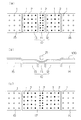
図2は、上述した塗布ノズル21および異物検出機構22と、搬送状態にある基板100との関係を示す側面図である。
FIG. 2 is a side view showing the relationship between the coating
上述した図1においては、説明の便宜上塗布ノズル21と異物検出機構22とを離隔した状態で表現しているが、異物検出機構22は、塗布ノズル21の側面に付設された構成を有する。すなわち、異物検出機構22は、塗布ノズル21に付設されたブラケット23と、ブラケット23に配設された軸24を中心として揺動可能な異物検知プレート25と、この異物検知プレート25の揺動を検出するセンサ26とから構成される。
In FIG. 1 described above, for convenience of explanation, the
異物検知プレート25は、基板100の搬送方向と直交する方向の全域に渡る長さを有する。この異物検知プレート25は、通常の、塗布液101の塗布状態においては、図2(a)に示すように、鉛直方向を向いている。そして、この異物検出プレート25が基板100上の異物102と当接した場合には、図2(a)に示す状態から図2(b)に示す状態まで揺動する。この異物検知プレート25の揺動動作は、センサ26により検知される。
The foreign
そして、センサ26からの信号が装置の制御部に送信され、基板100の搬送が停止される。これにより、塗布ノズル21が異物102と衝突して、塗布ノズルが損傷し、あるいは、塗布ノズルの位置に誤差が生じ、その後の塗布作業が不可能となるという問題を未然に防止することが可能となる。
Then, a signal from the
図3は、浮上ステージ14、異物検出ステージ12、塗布ステージ11および浮上ステージ15の構成を説明する図である。ここで、図3(a)は、浮上ステージ14、異物検出ステージ12、塗布ステージ11および浮上ステージ15の平面図であり、図3(b)は浮上ステージ14、異物検出ステージ12、塗布ステージ11および浮上ステージ15を塗布ノズル21および基板100とともに示す側面図である。また、図3(c)は、図3(a)の変形例を示す平面図である。
FIG. 3 is a diagram illustrating the configuration of the
図3(a)に示すように、一対の浮上ステージ14、15には、基板100との間の領域に気体を噴出する噴出口1が形成されている。また、異物検出ステージ12と塗布ステージ11とには、基板100との間の領域に気体を噴出する噴出口1と、基板100との間の領域から気体を排気する排気口2とが形成されている。なお、異物検出ステージ12における排気口2および噴出口1のピッチは、塗布ステージ11における排気口2および噴出口1のピッチより大きく設定されている。
As shown in FIG. 3A, the pair of levitation stages 14, 15 is formed with a
後述するように、基板100の浮上位置の精度は、一対の浮上ステージ14、15より異物検出ステージ12の方が高精度である必要があり、また、異物検出ステージ12より塗布ステージ11の方が高精度である必要がある。このため、各ステージ表面の加工精度も、一対の浮上ステージ14、15より異物検出ステージ12の方が高精度となっており、また、異物検出ステージ12より塗布ステージ11の方が高精度となっている。
As will be described later, the accuracy of the floating position of the
なお、異物検出ステージ12は、その基板100の搬送方向の長さY(図3における左右方向の長さ)が、図2に示す塗布ノズル21による塗布液101の塗布位置と異物検出機構22における異物検出プレート25による異物の検出位置との、基板100の搬送方向の距離Xより大きくなるように設定されている。
The foreign
図3(c)は図3(a)に示す実施形態の変形例を示している。図3(c)に示す実施形態においては、図3(a)に示す異物検出ステージ12および塗布ステージ11の表面部分を共通化した単一の精密浮上ステージ16としている。しかしながら、後述する第1、第2排気手段および第1、第2気体供給手段は、図3(a)に示す実施形態と同一である。すなわち、図3(c)に示す実施形態と図3(a)に示す実施形態は、その表面部分が異なるだけであり、図3(c)に示す精密浮上ステージ16は、図3(a)に示す異物検出ステージ12および塗布ステージ11から構成されるものである。このため、精密浮上ステージ16の表面の加工精度は、一対の浮上ステージ14、15より高精度となっており、また、これらの領域のうち、異物検出ステージ12に相当する領域より、塗布ステージ11に相当する領域の方が高精度となっている。
FIG. 3C shows a modification of the embodiment shown in FIG. In the embodiment shown in FIG. 3C, a single
図4は、異物検出ステージ12および塗布ステージ11に対する気体の排気および供給手段を示す概要図である。
FIG. 4 is a schematic diagram showing gas exhaust and supply means for the foreign
塗布ステージ11における各排気口2は、流量調整バルブ48b、流量計44b、圧力計49bを介して、ブロア41と接続されている。流量計44bおよび圧力計49bの検出値に基づいて流量調整バルブ48bを制御することにより、塗布ステージ11における排気口2からの排気量を所定の値に制御することができる。また、塗布ステージ11における各噴出口1は、圧力調整レギュレータ46a、流量調整バルブ48a、流量計44a、圧力計49aを介して、圧縮空気の供給源47と接続されている。流量計44aおよび圧力計49aの検出値に基づいて流量調整バルブ48aおよび圧力調整レギュレータ46aを制御することにより、塗布ステージ11における噴出口1からの気体の噴出量および噴出圧力を所定の値に制御することができる。
Each
同様に、異物検出ステージ12における各排気口2は、流量調整バルブ48d、流量計44d、圧力計49dを介して、ブロア42と接続されている。流量計44dおよび圧力計49dの検出値に基づいて流量調整バルブ48dを制御することにより、異物検出ステージ12における排気口2からの排気量を所定の値に制御することができる。また、異物検出ステージ12における各噴出口1は、圧力調整レギュレータ46c、流量調整バルブ48c、流量計44c、圧力計49cを介して、圧縮空気の供給源47と接続されている。流量計44cおよび圧力計49cの検出値に基づいて流量調整バルブ48cおよび圧力調整レギュレータ46cを制御することにより、異物検出ステージ12における噴出口1からの気体の噴出量および噴出圧力を所定の値に制御することができる。
Similarly, each
異物検出ステージ12に形成された排気口2から排気を行うための流量調整バルブ48d、流量計44d、圧力計49d、ブロア42は、この発明に係る第1排気手段を構成し、異物検出ステージ12に形成された噴出口1から気体を噴出するための圧力調整レギュレータ46c、流量調整バルブ48c、流量計44c、圧力計49c、圧縮空気の供給源47はこの発明に係る第1気体供給手段を構成する。同様に、塗布ステージ11に形成された排気口2から排気を行うための流量調整バルブ48b、流量計44b、圧力計49b、ブロア41は、この発明に係る第2排気手段を構成し、塗布ステージ11に形成された噴出口1から気体を噴出するための圧力調整レギュレータ46a、流量調整バルブ48a、流量計44a、圧力計49a、圧縮空気の供給源47はこの発明に係る第2気体供給手段を構成する。
The flow
なお、一対の浮上ステージ14、15における各噴出口1は、図示は省略しているが、上述した圧力調整レギュレータ46a、46c、流量調整バルブ48a、48c、流量計44a、44c、圧力計49a、49cと同様の構成を介して、圧縮空気の供給源47と接続されている。
In addition, although each
塗布ステージ11において基板100に塗布液を塗布するときには、塗布ノズル21の下端部と基板100の表面との距離を正確に維持するため、基板100の下面と塗布ステージ11の表面との距離を高精度に維持する必要がある。また、異物検出ステージ12においては、異物を正確に検出するため、基板100の下面と異物検出ステージ12の表面との距離をある程度正確に維持する必要があるが、一対の浮上ステージ14、15においては、単に基板100を浮上させて搬送すればよいことから、基板100の下面と浮上ステージ14、15の表面との距離は多少ラフでも問題はない。
When the coating liquid is applied to the
このため、上述したように、各ステージ表面の加工精度は、一対の浮上ステージ14、15より異物検出ステージ12の方が高精度となっており、また、異物検出ステージ12より塗布ステージ11の方が高精度となっている。また、一対の浮上ステージ14、15では単に基板100との間の領域に気体を噴出する噴出口1のみが形成されているのに対し、異物検出ステージ12と塗布ステージ11には、基板100との間の領域に気体を噴出する噴出口1と、基板100との間の領域から気体を排気する排気口2とが形成され、気体の噴出量と排気量とを制御することにより、基板100と異物検出ステージ12と塗布ステージ11との距離を精密に制御している。さらには、塗布ステージ11においては、基板100と塗布ステージ11との距離をより精密に制御するため、上述したように、異物検出ステージ12における排気口2および噴出口1のピッチより小さなピッチで排気口2および噴出口1が形成されるとともに、異物検出ステージ12と塗布ステージ11において、個別の排気手段および気体供給手段を採用している。
For this reason, as described above, the processing accuracy of the surface of each stage is higher in the foreign
以上のような構成を有する塗布装置において基板100に塗布液を塗布するときには、浮上ステージ14、異物検出ステージ12、塗布ステージ11および浮上ステージ15における噴出口1から気体を噴出するとともに、異物検出ステージ12および塗布ステージ11における排気口2から気体を排気することにより、基板100を浮上させる。そして、この状態において、基板搬送チャック31により基板100の端縁を保持して、基板100を浮上ステージ14、異物検出ステージ12、塗布ステージ11および浮上ステージ15に沿って移動させる。
When a coating solution is applied to the
このときの、基板100の高さ位置は、図示しないセンサにより常に検出される。そして、浮上ステージ14および浮上ステージ15においては、基板100の高さ位置に基づいて、噴出口1から噴出される気体の噴出量および噴出圧力が制御される。また、異物検出ステージ12および塗布ステージ11においては、噴出口1から噴出される気体の噴出量および噴出圧力が制御されるとともに、排気口2から排気される気体の排気量が制御される。
At this time, the height position of the
図3(b)に示すように、基板100が浮上ステージ14上を通過するときには、基板100の下面と浮上ステージ14の表面との距離Dは所定の高さに維持される。また、基板100が異物検出ステージ12上を通過するときには、基板100上の異物を正確に検出するため、基板100の下面と異物検出ステージ12の表面との距離Dは、浮上ステージ14に比べて低い位置に変更され、より高精度に維持されている。
As shown in FIG. 3B, when the
ここで、異物検出ステージ12における基板100の搬送方向の長さYは、上述したように、塗布ノズル21による塗布液101の塗布位置と異物検出機構22における異物検出プレート25による異物の検出位置との距離Xより大きくなるように設定されている。このため、基板100と異物検出機構22との衝突を有効に防止することが可能となる。なお、基板100が浮上ステージ14から異物検出ステージ12に移動するときに、上述した距離Dを変更するために所定の距離が必要である場合には、異物検出ステージ12における基板100の搬送方向の長さYを、塗布ノズル21による塗布液101の塗布位置と異物検出機構22における異物検出プレート25による異物の検出位置との距離Xに、この高さの変更に要する距離を加算した長さとすることが好ましい。
Here, as described above, the length Y of the foreign
引き続き基板100が搬送され、基板100が異物検出ステージ12から塗布ステージ11に移動するときには、基板100の下面と塗布ステージ11の表面との距離Dがさらに低い位置に変更され、より高精度に維持される。
When the
このとき、この塗布装置においては、排気手段として、異物検出ステージ12に形成された排気口2から排気を行うための第1排気手段と、塗布ステージ11に形成された排気口2から排気を行うための第2排気手段との個別の排気手段を使用するとともに、気体供給手段として、異物検出ステージ12に形成された噴出口1から気体を噴出するための係る第1気体供給手段と、塗布ステージ11に形成された噴出口1から気体を噴出するための係る第2気体供給手段との個別の気体供給手段を使用している。このため、基板100の高さ位置を正確に制御して、塗布液の塗布と異物の検出とを正確に実行することが可能となる。
At this time, in this coating apparatus, exhaust is performed from the
さらに基板100が搬送され、塗布液101の塗布が終了した基板100が塗布ステージ11から浮上ステージ15に移動すれば、基板100の下面と浮上ステージ15の表面との距離Dは、浮上ステージ14と同程度に変更される。
When the
次に、この発明の他の実施形態について説明する。図5は、この発明の第2実施形態に係る塗布装置の平面概要図である。また、図6は、浮上ステージ14、異物検出ステージ12、塗布ステージ11、振動防止ステージ13および浮上ステージ15の構成を説明する図である。ここで、図6(a)は、浮上ステージ14、異物検出ステージ12、塗布ステージ11、振動防止ステージ13および浮上ステージ15の平面図であり、図6(b)は浮上ステージ14、異物検出ステージ12、塗布ステージ11、振動防止ステージ13および浮上ステージ15を塗布ノズル21および基板100とともに示す側面図である。また、図6(c)は、図6(a)の変形例を示す平面図である。さらに、図7は、異物検出ステージ12、塗布ステージ11および振動防止ステージ13に対する気体の排気および供給手段を示す概要図である。
Next, another embodiment of the present invention will be described. FIG. 5 is a schematic plan view of a coating apparatus according to the second embodiment of the present invention. FIG. 6 is a diagram illustrating the configuration of the
この第2実施形態に係る塗布装置は、上述した第1実施形態に係る塗布装置に対して、塗布ステージ11よりも基板の搬送方向の下流側、すなわち、塗布ステージ11と浮上ステージ15との間に、振動防止ステージ13を配置した構成を有する。その他の構成は、上述した第1実施形態と同様である。なお、上述した第1実施形態と同一の部材については、同一の符号を付して詳細な説明を省略する。
The coating apparatus according to the second embodiment is downstream of the
この第2実施形態に係る塗布装置においては、塗布ステージ11と浮上ステージ15との間に、振動防止ステージ13が配置された構成となっている。図6(a)に示すように、振動防止ステージ13には、基板100との間の領域に気体を噴出する噴出口1と、基板100との間の領域から気体を排気する排気口2とが形成されている。なお、振動防止ステージ13における排気口2および噴出口1のピッチは、異物検出ステージ12における排気口2および噴出口1のピッチと同ピッチであり、塗布ステージにおける排気口2および噴出口1のピッチより大きく設定されている。また、この振動防止ステージ13における基板100の浮上位置の精度は、異物検出ステージ12と同程度であればよい。このため、この振動防止ステージ13の表面の加工精度も、異物検出ステージ12と同程度となっている。
In the coating apparatus according to the second embodiment, a
図7に示すように、振動防止ステージ13における各排気口2は、流量調整バルブ48f、流量計44f、圧力計49fを介して、ブロア43と接続されている。流量計44fおよび圧力計49fの検出値に基づいて流量調整バルブ48fを制御することにより、振動防止ステージ13における排気口2からの排気量を所定の値に制御することができる。また、振動防止ステージ13における各噴出口1は、圧力調整レギュレータ46e、流量調整バルブ48e、流量計44e、圧力計49eを介して、圧縮空気の供給源47と接続されている。流量計44eおよび圧力計49eの検出値に基づいて流量調整バルブ48eおよび圧力調整レギュレータ46eを制御することにより、振動防止ステージ13における噴出口1からの気体の噴出量および噴出圧力を所定の値に制御することができる。
As shown in FIG. 7, each
振動防止ステージ13に形成された排気口2から排気を行うための流量調整バルブ48f、流量計44f、圧力計49f、ブロア43は、この発明に係る第3排気手段を構成し、振動防止ステージ13に形成された噴出口1から気体を噴出するための圧力調整レギュレータ46e、流量調整バルブ48e、流量計44e、圧力計49e、圧縮空気の供給源47はこの発明に係る第3気体供給手段を構成する。
The flow
図6(c)は図6(a)に示す実施形態の変形例を示している。図6(c)に示す実施形態においては、図6(a)に示す異物検出ステージ12、塗布ステージ11および振動防止ステージ13の表面部分を共通化した単一の精密浮上ステージ17としている。しかしながら、上述した第1、第2、第3排気手段および第1、第2、第3気体供給手段は、図6(a)に示す実施形態と同一である。すなわち、図6(c)に示す実施形態と図6(a)に示す実施形態は、その表面部分が異なるだけであり、図6(c)に示す精密浮上ステージ17は、図3(a)に示す異物検出ステージ12、塗布ステージ11および振動防止ステージ13から構成されるものである。このため、精密浮上ステージ17の表面の加工精度は、一対の浮上ステージ14、15より高精度となっており、また、これらの領域のうち、異物検出ステージ12および振動防止ステージ13に相当する領域より、塗布ステージ11に相当する領域の方が高精度となっている。
FIG. 6C shows a modification of the embodiment shown in FIG. In the embodiment shown in FIG. 6C, a single
上述した第1実施形態においては、浮上ステージ15において、塗布ステージ11で塗布液が塗布された基板100に振動が生ずる場合がある。このため、この第2実施形態においては、異物検出ステージ12と同程度の精度で基板100を搬送する振動防止ステージ13を、塗布ステージ11と浮上ステージ15との間に配置している。なお、振動防止ステージ13においては、基板100の下面と振動防止ステージ13の表面との距離を、異物検出ステージ12と同様とすればよい。
In the first embodiment described above, in the
この第2実施形態に係る塗布装置においても、第1実施形態に係る塗布装置と同様、第1、第2、第3排気手段および第1、第2、第3気体供給手段の作用により、基板100の高さ位置を正確に制御して、塗布液の塗布と異物の検出とを正確に実行することが可能となる。 Also in the coating apparatus according to the second embodiment, similarly to the coating apparatus according to the first embodiment, the first, second, and third exhaust means and the first, second, and third gas supply means function to form the substrate. It is possible to accurately control the height position of 100 and accurately perform the application of the coating liquid and the detection of the foreign matter.
1 噴出口
2 排気口
10 精密浮上ステージ
11 塗布ステージ
12 異物検出ステージ
13 振動防止ステージ
14 浮上ステージ
15 浮上ステージ
16 精密浮上ステージ
17 精密浮上ステージ
21 塗布ノズル
22 異物検出機構
31 基板搬送チャック
32 ガイドレール
41 ブロア
42 ブロア
43 ブロア
47 圧縮空気の供給源
100 基板
DESCRIPTION OF
Claims (7)
一方向に移動する基板の表面に塗布液を塗布する塗布ノズルと、
前記塗布ノズルに対し、基板の搬送方向の上流側に配置され、基板の表面に存在する異物を検出する異物検出機構と、
基板との間の領域に気体を噴出する噴出口が形成された一対の浮上ステージと、
前記一対の浮上ステージの間に配置され、基板との間の領域に気体を噴出する噴出口と、基板との間の領域から気体を排気する排気口とが形成された精密浮上ステージと、
前記精密浮上ステージにおける基板の搬送方向の上流側に位置する排気口から、気体を排気するための第1排気手段と、
前記精密浮上ステージにおける前記第1排気手段により排気がなされる排気口に対し、前記基板の搬送方向の下流側に位置する排気口から、気体を排気するための第2排気手段と、を備え、
前記精密浮上ステージは、前記異物検出機構により異物を検出するために使用される異物検出ステージと、前記異物検出ステージよりも基板の搬送方向の下流側に配置され前記塗布ノズルにより塗布液を塗布するために使用される塗布ステージとを備えるとともに、
前記第1排気手段は、前記異物検出ステージに形成された排気口から排気を行うとともに、前記第2排気手段は、前記塗布ステージに形成された排気口から排気を行い、
前記第1排気手段および前記第2排気手段からの排気を制御することで、前記異物検出ステージでの基板の高さより前記塗布ステージでの基板の高さを低くすることを特徴とする塗布装置。 In a coating apparatus that applies a coating liquid to the surface of the substrate by moving the substrate in one direction while the substrate is levitated by supplying gas to the lower surface of the substrate,
A coating nozzle for coating the coating liquid on the surface of the substrate moving in one direction;
A foreign matter detection mechanism that is disposed upstream of the coating nozzle in the substrate transport direction and detects foreign matter existing on the surface of the substrate;
A pair of levitation stages in which a jet port for jetting gas is formed in a region between the substrate and the substrate;
A precision levitation stage that is disposed between the pair of levitation stages, and has an ejection port for ejecting gas to a region between the substrate and an exhaust port for exhausting gas from the region between the substrate;
A first exhaust means for exhausting gas from an exhaust port located upstream in the transport direction of the substrate in the precision levitation stage;
A second exhaust means for exhausting gas from an exhaust port located downstream in the transport direction of the substrate with respect to an exhaust port exhausted by the first exhaust means in the precision levitation stage ;
The precision levitation stage is disposed on the downstream side in the substrate transport direction with respect to the foreign matter detection stage used for detecting foreign matter by the foreign matter detection mechanism, and applies the coating liquid by the coating nozzle. And a coating stage used for
The first exhaust means exhausts from an exhaust port formed in the foreign matter detection stage, and the second exhaust means exhausts from an exhaust port formed in the coating stage,
The coating apparatus characterized in that the height of the substrate on the coating stage is made lower than the height of the substrate on the foreign matter detection stage by controlling the exhaust from the first exhaust means and the second exhaust means .
前記異物検出ステージは、その基板の搬送方向の長さが、前記塗布ノズルによる塗布液の塗布位置と前記異物検出機構による異物の検出位置との基板の搬送方向の距離より大きい塗布装置。 The coating apparatus according to claim 1 ,
The foreign matter detection stage is a coating apparatus in which the length of the substrate in the transport direction is larger than the distance in the transport direction of the substrate between the coating liquid application position by the coating nozzle and the foreign matter detection position by the foreign matter detection mechanism.
前記異物検出ステージに形成された噴出口から気体を噴出するための第1気体供給手段と、
前記塗布ステージに形成された噴出口から気体を噴出するための第2気体供給手段と、
を備える塗布装置。 The coating apparatus according to claim 2 ,
First gas supply means for jetting gas from the jet port formed in the foreign object detection stage;
A second gas supply means for jetting gas from a jet port formed in the coating stage;
A coating apparatus comprising:
前記異物検出ステージにおける前記排気口および前記噴出口のピッチが、前記塗布ステージにおける前記排気口および前記噴出口のピッチより大きい塗布装置。 In the coating device according to claim 3 ,
A coating apparatus in which a pitch between the exhaust port and the jet port in the foreign substance detection stage is larger than a pitch between the exhaust port and the jet port in the coating stage.
前記精密浮上ステージは、前記塗布ステージよりも基板の搬送方向の下流側に配置された振動防止ステージをさらに備えるとともに、
前記振動防止ステージに形成された排気口から排気を行う第3排気手段を備えた塗布装置。 The coating apparatus according to claim 1 ,
The precision levitation stage further includes an anti-vibration stage disposed downstream of the coating stage in the substrate transport direction from the coating stage,
The coating apparatus provided with the 3rd exhaustion means which exhausts from the exhaust port formed in the said vibration prevention stage.
前記振動防止ステージに形成された噴出口から気体を噴出するための第3気体供給手段をさらに備える塗布装置。 The coating apparatus according to claim 5 , wherein
A coating apparatus further comprising third gas supply means for jetting gas from a jet port formed in the vibration preventing stage.
前記振動防止ステージにおける前記排気口および前記噴出口のピッチが、前記塗布ステージにおける前記排気口および前記噴出口のピッチより大きい塗布装置。 The coating apparatus according to claim 6 , wherein
A coating apparatus in which a pitch between the exhaust port and the jet port in the vibration preventing stage is larger than a pitch between the exhaust port and the jet port in the coating stage.
Priority Applications (4)
| Application Number | Priority Date | Filing Date | Title |
|---|---|---|---|
| JP2010081564A JP5437134B2 (en) | 2010-03-31 | 2010-03-31 | Coating device |
| TW099135112A TWI445578B (en) | 2010-03-31 | 2010-10-14 | Coating device |
| KR1020100126946A KR101281305B1 (en) | 2010-03-31 | 2010-12-13 | Coating apparatus |
| CN201110042994XA CN102205296B (en) | 2010-03-31 | 2011-02-18 | Coating device |
Applications Claiming Priority (1)
| Application Number | Priority Date | Filing Date | Title |
|---|---|---|---|
| JP2010081564A JP5437134B2 (en) | 2010-03-31 | 2010-03-31 | Coating device |
Publications (2)
| Publication Number | Publication Date |
|---|---|
| JP2011212544A JP2011212544A (en) | 2011-10-27 |
| JP5437134B2 true JP5437134B2 (en) | 2014-03-12 |
Family
ID=44694528
Family Applications (1)
| Application Number | Title | Priority Date | Filing Date |
|---|---|---|---|
| JP2010081564A Active JP5437134B2 (en) | 2010-03-31 | 2010-03-31 | Coating device |
Country Status (4)
| Country | Link |
|---|---|
| JP (1) | JP5437134B2 (en) |
| KR (1) | KR101281305B1 (en) |
| CN (1) | CN102205296B (en) |
| TW (1) | TWI445578B (en) |
Families Citing this family (12)
| Publication number | Priority date | Publication date | Assignee | Title |
|---|---|---|---|---|
| KR101362292B1 (en) | 2012-06-04 | 2014-02-13 | 주식회사 나래나노텍 | Improved Apparatus and Method of Coating Both Sides of Film |
| KR102066041B1 (en) * | 2012-12-03 | 2020-02-11 | 세메스 주식회사 | Substrate treating apparatus |
| JP6518891B2 (en) * | 2014-08-01 | 2019-05-29 | 株式会社ブイ・テクノロジー | Transport device |
| JP2018043200A (en) * | 2016-09-15 | 2018-03-22 | 株式会社Screenホールディングス | Coating applicator and application method |
| JP6860356B2 (en) * | 2017-01-20 | 2021-04-14 | 株式会社Screenホールディングス | Coating device and coating method |
| KR102027116B1 (en) * | 2018-04-04 | 2019-10-01 | 주식회사 필옵틱스 | Non―contact adsorption device of flexible material |
| KR102134161B1 (en) * | 2018-08-23 | 2020-07-21 | 세메스 주식회사 | Apparatus and method for treating substrate |
| JP6896008B2 (en) * | 2019-03-19 | 2021-06-30 | 株式会社Screenホールディングス | Substrate processing equipment and substrate processing method |
| JP6916833B2 (en) * | 2019-04-18 | 2021-08-11 | 株式会社Screenホールディングス | Coating device and coating method |
| CN113070169B (en) * | 2021-04-19 | 2022-08-05 | 深圳市弘德胜自动化设备有限公司 | Electronic paper coating equipment |
| JP7316331B2 (en) * | 2021-09-02 | 2023-07-27 | 株式会社Screenホールディングス | SUBSTRATE PROCESSING APPARATUS AND SUBSTRATE PROCESSING METHOD |
| JP7470742B2 (en) | 2022-07-11 | 2024-04-18 | 株式会社Screenホールディングス | SUBSTRATE PROCESSING APPARATUS AND SUBSTRATE PROCESSING METHOD |
Family Cites Families (8)
| Publication number | Priority date | Publication date | Assignee | Title |
|---|---|---|---|---|
| JP4490779B2 (en) * | 2004-10-04 | 2010-06-30 | 大日本スクリーン製造株式会社 | Substrate processing equipment |
| US7643046B2 (en) * | 2005-12-21 | 2010-01-05 | Ricoh Company, Ltd. | Laser beam scanning device, image forming apparatus, and laser beam detecting method by the laser beam scanning device |
| JP4472630B2 (en) * | 2005-12-28 | 2010-06-02 | 大日本スクリーン製造株式会社 | Substrate processing equipment |
| JP4516034B2 (en) * | 2006-02-03 | 2010-08-04 | 東京エレクトロン株式会社 | Coating method, coating apparatus, and coating program |
| JP4809699B2 (en) * | 2006-03-20 | 2011-11-09 | 東京エレクトロン株式会社 | Coating method and coating apparatus |
| JP4318714B2 (en) * | 2006-11-28 | 2009-08-26 | 東京エレクトロン株式会社 | Coating device |
| JP2009043829A (en) * | 2007-08-07 | 2009-02-26 | Tokyo Ohka Kogyo Co Ltd | Coater and coating method |
| JP5303129B2 (en) * | 2007-09-06 | 2013-10-02 | 東京応化工業株式会社 | Coating apparatus and coating method |
-
2010
- 2010-03-31 JP JP2010081564A patent/JP5437134B2/en active Active
- 2010-10-14 TW TW099135112A patent/TWI445578B/en active
- 2010-12-13 KR KR1020100126946A patent/KR101281305B1/en active IP Right Grant
-
2011
- 2011-02-18 CN CN201110042994XA patent/CN102205296B/en active Active
Also Published As
| Publication number | Publication date |
|---|---|
| TWI445578B (en) | 2014-07-21 |
| TW201138984A (en) | 2011-11-16 |
| CN102205296A (en) | 2011-10-05 |
| CN102205296B (en) | 2013-10-30 |
| KR20110109798A (en) | 2011-10-06 |
| KR101281305B1 (en) | 2013-07-03 |
| JP2011212544A (en) | 2011-10-27 |
Similar Documents
| Publication | Publication Date | Title |
|---|---|---|
| JP5437134B2 (en) | Coating device | |
| WO2016136495A1 (en) | Gas floated workpiece support device and non-contact workpiece support method | |
| JP6023440B2 (en) | Coating device | |
| JP5399963B2 (en) | Substrate transfer apparatus and substrate processing apparatus | |
| CN1997576A (en) | Levitation transportation device and levitation transportation method | |
| JP5346643B2 (en) | Substrate coating apparatus and substrate coating method | |
| JP2008076170A (en) | Substrate inspection device | |
| JP5368326B2 (en) | Substrate processing apparatus and substrate processing method | |
| KR101081885B1 (en) | Substrate coater apparatus | |
| CN101683935A (en) | Device and method for rectifying transportation of flexible plate | |
| CN108325788B (en) | Coating device and coating method | |
| JP2004345814A (en) | Floatation transport device | |
| JP2007204278A (en) | Substrate floating carrying device | |
| JP4982292B2 (en) | Coating apparatus and coating method | |
| JP5372824B2 (en) | Substrate processing apparatus and substrate processing method | |
| KR102390540B1 (en) | Non-Contact Transfer device for Display panel | |
| JP4595841B2 (en) | Work transfer device | |
| JP6456904B2 (en) | Gas floating work support device | |
| JP2008068224A (en) | Slit nozzle, substrate treatment apparatus, and method for treating substrate | |
| JP2018114476A (en) | Apparatus and method for coating | |
| CN115739522B (en) | Substrate processing apparatus and substrate processing method | |
| KR102322675B1 (en) | Apparatus for dispensing droplet, and apparatus for processing substrate having the same | |
| JP6896008B2 (en) | Substrate processing equipment and substrate processing method | |
| KR20180122064A (en) | Apparatus for processing a substrate and Method for processing a substrate | |
| JP5862007B2 (en) | Substrate transfer apparatus, substrate transfer method, and coating apparatus using the same |
Legal Events
| Date | Code | Title | Description |
|---|---|---|---|
| A621 | Written request for application examination |
Free format text: JAPANESE INTERMEDIATE CODE: A621 Effective date: 20120514 |
|
| A977 | Report on retrieval |
Free format text: JAPANESE INTERMEDIATE CODE: A971007 Effective date: 20130809 |
|
| A131 | Notification of reasons for refusal |
Free format text: JAPANESE INTERMEDIATE CODE: A131 Effective date: 20130820 |
|
| A521 | Request for written amendment filed |
Free format text: JAPANESE INTERMEDIATE CODE: A523 Effective date: 20131010 |
|
| TRDD | Decision of grant or rejection written | ||
| A01 | Written decision to grant a patent or to grant a registration (utility model) |
Free format text: JAPANESE INTERMEDIATE CODE: A01 Effective date: 20131126 |
|
| A61 | First payment of annual fees (during grant procedure) |
Free format text: JAPANESE INTERMEDIATE CODE: A61 Effective date: 20131211 |
|
| R150 | Certificate of patent or registration of utility model |
Ref document number: 5437134 Country of ref document: JP Free format text: JAPANESE INTERMEDIATE CODE: R150 Free format text: JAPANESE INTERMEDIATE CODE: R150 |
|
| S533 | Written request for registration of change of name |
Free format text: JAPANESE INTERMEDIATE CODE: R313533 |
|
| R350 | Written notification of registration of transfer |
Free format text: JAPANESE INTERMEDIATE CODE: R350 |
|
| R250 | Receipt of annual fees |
Free format text: JAPANESE INTERMEDIATE CODE: R250 |
|
| R250 | Receipt of annual fees |
Free format text: JAPANESE INTERMEDIATE CODE: R250 |
|
| R250 | Receipt of annual fees |
Free format text: JAPANESE INTERMEDIATE CODE: R250 |
|
| R250 | Receipt of annual fees |
Free format text: JAPANESE INTERMEDIATE CODE: R250 |
|
| R250 | Receipt of annual fees |
Free format text: JAPANESE INTERMEDIATE CODE: R250 |
|
| R250 | Receipt of annual fees |
Free format text: JAPANESE INTERMEDIATE CODE: R250 |
|
| R250 | Receipt of annual fees |
Free format text: JAPANESE INTERMEDIATE CODE: R250 |
|
| R250 | Receipt of annual fees |
Free format text: JAPANESE INTERMEDIATE CODE: R250 |