JP2014158403A - 電源装置及び制御方法 - Google Patents
電源装置及び制御方法 Download PDFInfo
- Publication number
- JP2014158403A JP2014158403A JP2013029469A JP2013029469A JP2014158403A JP 2014158403 A JP2014158403 A JP 2014158403A JP 2013029469 A JP2013029469 A JP 2013029469A JP 2013029469 A JP2013029469 A JP 2013029469A JP 2014158403 A JP2014158403 A JP 2014158403A
- Authority
- JP
- Japan
- Prior art keywords
- output
- power supply
- circuit
- power
- value
- Prior art date
- Legal status (The legal status is an assumption and is not a legal conclusion. Google has not performed a legal analysis and makes no representation as to the accuracy of the status listed.)
- Granted
Links
Images


Classifications
-
- G—PHYSICS
- G06—COMPUTING; CALCULATING OR COUNTING
- G06F—ELECTRIC DIGITAL DATA PROCESSING
- G06F1/00—Details not covered by groups G06F3/00 - G06F13/00 and G06F21/00
- G06F1/26—Power supply means, e.g. regulation thereof
- G06F1/32—Means for saving power
- G06F1/3203—Power management, i.e. event-based initiation of a power-saving mode
- G06F1/3234—Power saving characterised by the action undertaken
- G06F1/3293—Power saving characterised by the action undertaken by switching to a less power-consuming processor, e.g. sub-CPU
-
- H—ELECTRICITY
- H02—GENERATION; CONVERSION OR DISTRIBUTION OF ELECTRIC POWER
- H02M—APPARATUS FOR CONVERSION BETWEEN AC AND AC, BETWEEN AC AND DC, OR BETWEEN DC AND DC, AND FOR USE WITH MAINS OR SIMILAR POWER SUPPLY SYSTEMS; CONVERSION OF DC OR AC INPUT POWER INTO SURGE OUTPUT POWER; CONTROL OR REGULATION THEREOF
- H02M3/00—Conversion of dc power input into dc power output
- H02M3/22—Conversion of dc power input into dc power output with intermediate conversion into ac
- H02M3/24—Conversion of dc power input into dc power output with intermediate conversion into ac by static converters
- H02M3/28—Conversion of dc power input into dc power output with intermediate conversion into ac by static converters using discharge tubes with control electrode or semiconductor devices with control electrode to produce the intermediate ac
- H02M3/285—Single converters with a plurality of output stages connected in parallel
-
- H—ELECTRICITY
- H02—GENERATION; CONVERSION OR DISTRIBUTION OF ELECTRIC POWER
- H02M—APPARATUS FOR CONVERSION BETWEEN AC AND AC, BETWEEN AC AND DC, OR BETWEEN DC AND DC, AND FOR USE WITH MAINS OR SIMILAR POWER SUPPLY SYSTEMS; CONVERSION OF DC OR AC INPUT POWER INTO SURGE OUTPUT POWER; CONTROL OR REGULATION THEREOF
- H02M3/00—Conversion of dc power input into dc power output
- H02M3/22—Conversion of dc power input into dc power output with intermediate conversion into ac
- H02M3/24—Conversion of dc power input into dc power output with intermediate conversion into ac by static converters
- H02M3/28—Conversion of dc power input into dc power output with intermediate conversion into ac by static converters using discharge tubes with control electrode or semiconductor devices with control electrode to produce the intermediate ac
- H02M3/325—Conversion of dc power input into dc power output with intermediate conversion into ac by static converters using discharge tubes with control electrode or semiconductor devices with control electrode to produce the intermediate ac using devices of a triode or a transistor type requiring continuous application of a control signal
- H02M3/335—Conversion of dc power input into dc power output with intermediate conversion into ac by static converters using discharge tubes with control electrode or semiconductor devices with control electrode to produce the intermediate ac using devices of a triode or a transistor type requiring continuous application of a control signal using semiconductor devices only
- H02M3/33561—Conversion of dc power input into dc power output with intermediate conversion into ac by static converters using discharge tubes with control electrode or semiconductor devices with control electrode to produce the intermediate ac using devices of a triode or a transistor type requiring continuous application of a control signal using semiconductor devices only having more than one ouput with independent control
-
- H—ELECTRICITY
- H02—GENERATION; CONVERSION OR DISTRIBUTION OF ELECTRIC POWER
- H02M—APPARATUS FOR CONVERSION BETWEEN AC AND AC, BETWEEN AC AND DC, OR BETWEEN DC AND DC, AND FOR USE WITH MAINS OR SIMILAR POWER SUPPLY SYSTEMS; CONVERSION OF DC OR AC INPUT POWER INTO SURGE OUTPUT POWER; CONTROL OR REGULATION THEREOF
- H02M1/00—Details of apparatus for conversion
- H02M1/0003—Details of control, feedback or regulation circuits
- H02M1/0025—Arrangements for modifying reference values, feedback values or error values in the control loop of a converter
-
- H—ELECTRICITY
- H02—GENERATION; CONVERSION OR DISTRIBUTION OF ELECTRIC POWER
- H02M—APPARATUS FOR CONVERSION BETWEEN AC AND AC, BETWEEN AC AND DC, OR BETWEEN DC AND DC, AND FOR USE WITH MAINS OR SIMILAR POWER SUPPLY SYSTEMS; CONVERSION OF DC OR AC INPUT POWER INTO SURGE OUTPUT POWER; CONTROL OR REGULATION THEREOF
- H02M1/00—Details of apparatus for conversion
- H02M1/0064—Magnetic structures combining different functions, e.g. storage, filtering or transformation
-
- H—ELECTRICITY
- H02—GENERATION; CONVERSION OR DISTRIBUTION OF ELECTRIC POWER
- H02M—APPARATUS FOR CONVERSION BETWEEN AC AND AC, BETWEEN AC AND DC, OR BETWEEN DC AND DC, AND FOR USE WITH MAINS OR SIMILAR POWER SUPPLY SYSTEMS; CONVERSION OF DC OR AC INPUT POWER INTO SURGE OUTPUT POWER; CONTROL OR REGULATION THEREOF
- H02M3/00—Conversion of dc power input into dc power output
- H02M3/02—Conversion of dc power input into dc power output without intermediate conversion into ac
- H02M3/04—Conversion of dc power input into dc power output without intermediate conversion into ac by static converters
- H02M3/10—Conversion of dc power input into dc power output without intermediate conversion into ac by static converters using discharge tubes with control electrode or semiconductor devices with control electrode
- H02M3/145—Conversion of dc power input into dc power output without intermediate conversion into ac by static converters using discharge tubes with control electrode or semiconductor devices with control electrode using devices of a triode or transistor type requiring continuous application of a control signal
- H02M3/155—Conversion of dc power input into dc power output without intermediate conversion into ac by static converters using discharge tubes with control electrode or semiconductor devices with control electrode using devices of a triode or transistor type requiring continuous application of a control signal using semiconductor devices only
- H02M3/156—Conversion of dc power input into dc power output without intermediate conversion into ac by static converters using discharge tubes with control electrode or semiconductor devices with control electrode using devices of a triode or transistor type requiring continuous application of a control signal using semiconductor devices only with automatic control of output voltage or current, e.g. switching regulators
- H02M3/158—Conversion of dc power input into dc power output without intermediate conversion into ac by static converters using discharge tubes with control electrode or semiconductor devices with control electrode using devices of a triode or transistor type requiring continuous application of a control signal using semiconductor devices only with automatic control of output voltage or current, e.g. switching regulators including plural semiconductor devices as final control devices for a single load
- H02M3/1584—Conversion of dc power input into dc power output without intermediate conversion into ac by static converters using discharge tubes with control electrode or semiconductor devices with control electrode using devices of a triode or transistor type requiring continuous application of a control signal using semiconductor devices only with automatic control of output voltage or current, e.g. switching regulators including plural semiconductor devices as final control devices for a single load with a plurality of power processing stages connected in parallel
-
- H—ELECTRICITY
- H02—GENERATION; CONVERSION OR DISTRIBUTION OF ELECTRIC POWER
- H02M—APPARATUS FOR CONVERSION BETWEEN AC AND AC, BETWEEN AC AND DC, OR BETWEEN DC AND DC, AND FOR USE WITH MAINS OR SIMILAR POWER SUPPLY SYSTEMS; CONVERSION OF DC OR AC INPUT POWER INTO SURGE OUTPUT POWER; CONTROL OR REGULATION THEREOF
- H02M3/00—Conversion of dc power input into dc power output
- H02M3/22—Conversion of dc power input into dc power output with intermediate conversion into ac
- H02M3/24—Conversion of dc power input into dc power output with intermediate conversion into ac by static converters
- H02M3/28—Conversion of dc power input into dc power output with intermediate conversion into ac by static converters using discharge tubes with control electrode or semiconductor devices with control electrode to produce the intermediate ac
- H02M3/325—Conversion of dc power input into dc power output with intermediate conversion into ac by static converters using discharge tubes with control electrode or semiconductor devices with control electrode to produce the intermediate ac using devices of a triode or a transistor type requiring continuous application of a control signal
- H02M3/335—Conversion of dc power input into dc power output with intermediate conversion into ac by static converters using discharge tubes with control electrode or semiconductor devices with control electrode to produce the intermediate ac using devices of a triode or a transistor type requiring continuous application of a control signal using semiconductor devices only
- H02M3/3353—Conversion of dc power input into dc power output with intermediate conversion into ac by static converters using discharge tubes with control electrode or semiconductor devices with control electrode to produce the intermediate ac using devices of a triode or a transistor type requiring continuous application of a control signal using semiconductor devices only having at least two simultaneously operating switches on the input side, e.g. "double forward" or "double (switched) flyback" converter
-
- H—ELECTRICITY
- H02—GENERATION; CONVERSION OR DISTRIBUTION OF ELECTRIC POWER
- H02M—APPARATUS FOR CONVERSION BETWEEN AC AND AC, BETWEEN AC AND DC, OR BETWEEN DC AND DC, AND FOR USE WITH MAINS OR SIMILAR POWER SUPPLY SYSTEMS; CONVERSION OF DC OR AC INPUT POWER INTO SURGE OUTPUT POWER; CONTROL OR REGULATION THEREOF
- H02M3/00—Conversion of dc power input into dc power output
- H02M3/22—Conversion of dc power input into dc power output with intermediate conversion into ac
- H02M3/24—Conversion of dc power input into dc power output with intermediate conversion into ac by static converters
- H02M3/28—Conversion of dc power input into dc power output with intermediate conversion into ac by static converters using discharge tubes with control electrode or semiconductor devices with control electrode to produce the intermediate ac
- H02M3/325—Conversion of dc power input into dc power output with intermediate conversion into ac by static converters using discharge tubes with control electrode or semiconductor devices with control electrode to produce the intermediate ac using devices of a triode or a transistor type requiring continuous application of a control signal
- H02M3/335—Conversion of dc power input into dc power output with intermediate conversion into ac by static converters using discharge tubes with control electrode or semiconductor devices with control electrode to produce the intermediate ac using devices of a triode or a transistor type requiring continuous application of a control signal using semiconductor devices only
- H02M3/33569—Conversion of dc power input into dc power output with intermediate conversion into ac by static converters using discharge tubes with control electrode or semiconductor devices with control electrode to produce the intermediate ac using devices of a triode or a transistor type requiring continuous application of a control signal using semiconductor devices only having several active switching elements
- H02M3/33576—Conversion of dc power input into dc power output with intermediate conversion into ac by static converters using discharge tubes with control electrode or semiconductor devices with control electrode to produce the intermediate ac using devices of a triode or a transistor type requiring continuous application of a control signal using semiconductor devices only having several active switching elements having at least one active switching element at the secondary side of an isolation transformer
- H02M3/33584—Bidirectional converters
Abstract
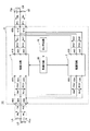
【解決手段】共通の出力端子161に接続された複数の電源回路111,112と、出力端子161の出力値が出力端子161の出力目標値に追従するように複数の電源回路111,112の出力を制御する制御回路150とを備える、電源装置であって、制御回路150は、出力端子161の出力値と出力端子161の出力目標値との間に所定値以下の乖離が発生した場合、複数の電源回路111,112の一部の電源回路の出力を変化させることを特徴とする、電源装置。
【選択図】図1
Description
共通の出力ノードに接続された複数の電源回路と、
前記出力ノードの出力値が前記出力ノードの出力目標値に追従するように前記複数の電源回路の出力を制御する制御部とを備える、電源装置であって、
前記制御部は、前記出力値と前記出力目標値との間に所定値以下の乖離が発生した場合、前記複数の電源回路の一部の電源回路の出力を変化させることを特徴とする、電源装置を提供するものである。
複数の電源回路が接続される共通の出力ノードの出力値が前記出力ノードの出力目標値に追従するように前記複数の電源回路の出力を制御する方法であって、
前記出力値と前記出力目標値との間に所定値以下の乖離が発生した場合、前記複数の電源回路の一部の電源回路の出力を変化させることを特徴とする、制御方法を提供するものである。
図1は、本発明に係る電源装置の第1の実施形態である電力変換回路110を備える電力変換回路システム100の構成を示した図である。電力変換回路システム100は、例えば、電力変換回路110と、制御回路150と、センサ回路170とを含んで構成された電力変換装置である。
図2は、図1に示した電力変換回路110の動作例を示したタイミングチャートである。図2は、電力変換回路110の制御回路150が、出力端子161の出力値Doが出力目標値Dotに追従するように、電源回路111の出力電力Wo1の大きさ及び電源回路112の出力電力Wo2の大きさを制御している状態を示している。制御回路150は、電源回路111,112の制御パラメータP1,P2の値を変化させて、出力電力Wo1の大きさ及び出力電力Wo2の大きさを制御する。
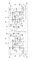
図4は、本発明に係る電源装置の第2の実施形態である電力変換回路10を備える電力変換回路システム101を示す図である。上述の実施形態と同様の構成及び効果についての説明は省略する。電力変換回路システム101は、電力変換回路10と、制御回路50と、センサ回路70とを含んで構成された電力変換装置である。
上記電力変換回路システム101の動作について、図4乃至図6を用いて説明する。例えば、電力変換回路10の電力変換モードをモードFとして動作させることを要求する外部信号が入力されてきた場合には、制御回路50の電力変換モード決定処理部502は、電力変換回路10の電力変換モードをモードFとして決定する。このとき、第2入出力ポートPC1に入力された電圧が1次側変換回路20の昇圧機能によって昇圧され、その昇圧された電圧が電力変換回路10のDC−DCコンバータ回路としての機能によって第3入出力ポートPB1側へと伝送され、さらに、2次側変換回路30の降圧機能によって降圧されて第4入出力ポートPD1から出力される。
1次側変換回路20の昇降圧比
=第2入出力ポートPC1の電圧/第1入出力ポートPA1の電圧
=δ1/T=α/T
2次側変換回路30の昇降圧比
=第4入出力ポートPD1の電圧/第3入出力ポートPB1の電圧
=δ2/T=α/T
と表される。つまり、1次側変換回路20と2次側変換回路30の昇降圧比は互いに同じ値(=α/T)である。
11,12,111,112 電源回路
20 1次側変換回路
30 2次側変換回路
50,150 制御回路
70,170 センサ回路
100,101 電力変換回路システム
160 入力端子
161 出力端子
166 電源
167 負荷
200 1次側フルブリッジ回路
202 1次側コイル
204 1次側磁気結合リアクトル
207 1次側第1アーム回路
211 1次側第2アーム回路
207m,211m 中点
298 1次側正極母線
299 1次側負極母線
300 2次側フルブリッジ回路
302 2次側コイル
304 2次側磁気結合リアクトル
307 2次側第1アーム回路
311 2次側第2アーム回路
307m,311m 中点
398 2次側正極母線
399 2次側負極母線
400 変圧器
PA 第1入出力ポート
PB 第3入出力ポート
PC 第2入出力ポート
PD 第4入出力ポート
U*,V* 上アーム
/U*,/V* 下アーム
Claims (10)
- 共通の出力ノードに接続された複数の電源回路と、
前記出力ノードの出力値が前記出力ノードの出力目標値に追従するように前記複数の電源回路の出力を制御する制御部とを備える、電源装置であって、
前記制御部は、前記出力値と前記出力目標値との間に所定値以下の乖離が発生した場合、前記複数の電源回路の一部の電源回路の出力を変化させることを特徴とする、電源装置。 - 前記制御部は、一部の電源回路の出力が変化した方向とは逆方向に前記出力目標値が変化した場合、該一部の電源回路の出力を変化させる、請求項1に記載の電源装置。
- 前記制御部は、一部の電源回路の出力が変化した方向とは逆方向に前記出力目標値が変化した場合、前記複数の電源回路のうち該一部の電源回路とは別の電源回路と該一部の電源回路との両出力をその出力差が所定の範囲内に収まるように設定する、請求項2に記載の電源装置。
- 前記制御部は、一部の電源回路の出力が変化した方向と同じ方向に前記出力目標値が変化した場合、前記複数の電源回路のうち該一部の電源回路とは別の電源回路の出力を変化させる、請求項1から3のいずれか一項に記載の電源装置。
- 前記制御部は、一部の電源回路の出力が変化した方向と同じ方向に前記出力目標値が変化した場合、前記複数の電源回路のうち該一部の電源回路とは別の電源回路と該一部の電源回路との両出力をその出力差が所定の範囲内に収まるように設定する、請求項4に記載の電源装置。
- 前記制御部は、前記出力ノードの出力値と前記出力目標値との間に前記所定値を超える乖離が発生した場合、前記複数の電源回路全部の出力を変化させる、請求項1から5のいずれか一項に記載の電源装置。
- 前記所定値は、前記複数の電源回路全部の出力を同時に変化させたときの前記出力ノードの出力値の最小変化量である、請求項1から6のいずれか一項に記載の電源装置。
- 前記複数の電源回路は、それぞれ、1次側回路と、前記1次側回路と変圧器で磁気結合する2次側回路とを備える電力変換装置であって、
前記電力変換装置は、
前記1次側回路の第1及び第2のポートと前記2次側回路の第3及び第4のポートとを合わせた4つのポートのうち、任意の2つのポート間で、前記1次側回路及び前記2次側回路それぞれに構成される電力変換部によって電力を変換することが可能な、請求項1から7のいずれか一項に記載の電源装置。 - 前記制御部は、前記電力変換部のデューティ比制御及び/又は位相制御によって、前記電力変換装置の出力を変化させる、請求項8に記載の電源装置。
- 複数の電源回路が接続される共通の出力ノードの出力値が前記出力ノードの出力目標値に追従するように前記複数の電源回路の出力を制御する方法であって、
前記出力値と前記出力目標値との間に所定値以下の乖離が発生した場合、前記複数の電源回路の一部の電源回路の出力を変化させることを特徴とする、制御方法。
Priority Applications (3)
| Application Number | Priority Date | Filing Date | Title |
|---|---|---|---|
| JP2013029469A JP5783195B2 (ja) | 2013-02-18 | 2013-02-18 | 電源装置及び制御方法 |
| US14/177,504 US9727125B2 (en) | 2013-02-18 | 2014-02-11 | Power supply system with a plurality of power supply circuits and control method of the same |
| CN201410052103.2A CN103997202B (zh) | 2013-02-18 | 2014-02-14 | 供电系统和控制方法 |
Applications Claiming Priority (1)
| Application Number | Priority Date | Filing Date | Title |
|---|---|---|---|
| JP2013029469A JP5783195B2 (ja) | 2013-02-18 | 2013-02-18 | 電源装置及び制御方法 |
Publications (2)
| Publication Number | Publication Date |
|---|---|
| JP2014158403A true JP2014158403A (ja) | 2014-08-28 |
| JP5783195B2 JP5783195B2 (ja) | 2015-09-24 |
Family
ID=51311243
Family Applications (1)
| Application Number | Title | Priority Date | Filing Date |
|---|---|---|---|
| JP2013029469A Active JP5783195B2 (ja) | 2013-02-18 | 2013-02-18 | 電源装置及び制御方法 |
Country Status (3)
| Country | Link |
|---|---|
| US (1) | US9727125B2 (ja) |
| JP (1) | JP5783195B2 (ja) |
| CN (1) | CN103997202B (ja) |
Cited By (1)
| Publication number | Priority date | Publication date | Assignee | Title |
|---|---|---|---|---|
| JP2016103892A (ja) * | 2014-11-27 | 2016-06-02 | トヨタ自動車株式会社 | 電力変換装置 |
Families Citing this family (7)
| Publication number | Priority date | Publication date | Assignee | Title |
|---|---|---|---|---|
| US9281808B2 (en) * | 2013-03-08 | 2016-03-08 | Microchip Technology Incorporated | Variable voltage level translator |
| JP5790709B2 (ja) * | 2013-05-21 | 2015-10-07 | トヨタ自動車株式会社 | 電力変換装置及び電力変換方法 |
| JP5958487B2 (ja) * | 2014-03-11 | 2016-08-02 | トヨタ自動車株式会社 | 電力変換装置及び電力変換方法 |
| JP6135663B2 (ja) * | 2014-12-26 | 2017-05-31 | トヨタ自動車株式会社 | 電力変換装置及び電力変換方法 |
| KR20210031215A (ko) * | 2019-09-11 | 2021-03-19 | 삼성전자주식회사 | 전자장치 및 그 제어방법 |
| CN110729904B (zh) * | 2019-09-29 | 2020-12-04 | 广州致远电子有限公司 | 全桥变换器电路变压器及全桥变换器电路 |
| US11777394B1 (en) * | 2022-04-20 | 2023-10-03 | Cisco Technology, Inc. | Modular power supply architecture optimized for flat efficiency across loadings |
Citations (6)
| Publication number | Priority date | Publication date | Assignee | Title |
|---|---|---|---|---|
| JPH10243637A (ja) * | 1997-02-27 | 1998-09-11 | Toshiba Corp | 電源回路及び不揮発性半導体記憶装置 |
| JP2000278949A (ja) * | 1999-03-25 | 2000-10-06 | Origin Electric Co Ltd | コンデンサ充電器 |
| JP2003111413A (ja) * | 2001-10-01 | 2003-04-11 | Nissin Electric Co Ltd | 双方向dc−dcコンバータ |
| JP2007336764A (ja) * | 2006-06-19 | 2007-12-27 | Yaskawa Electric Corp | 多相電力変換器 |
| JP2008141802A (ja) * | 2006-11-30 | 2008-06-19 | Mitsumi Electric Co Ltd | マルチフェーズdc−dcコンバータ |
| JP2011193713A (ja) * | 2010-02-17 | 2011-09-29 | Toyota Central R&D Labs Inc | 電力変換回路及び電力変換回路システム |
Family Cites Families (6)
| Publication number | Priority date | Publication date | Assignee | Title |
|---|---|---|---|---|
| JP4360726B2 (ja) | 2000-01-27 | 2009-11-11 | Tdkラムダ株式会社 | 並列電源装置 |
| US6674274B2 (en) * | 2001-02-08 | 2004-01-06 | Linear Technology Corporation | Multiple phase switching regulators with stage shedding |
| US8929099B2 (en) * | 2010-09-29 | 2015-01-06 | Bitrode Corporation | Bi-directional DC/DC converter and battery testing apparatus with converter |
| DE102010060957A1 (de) * | 2010-12-02 | 2012-06-06 | Sma Solar Technology Ag | Verfahren zum Betreiben eines Gleichspannungswandlers |
| JP5967871B2 (ja) * | 2011-06-27 | 2016-08-10 | トランスフォーム・ジャパン株式会社 | 電源装置 |
| JP5387651B2 (ja) * | 2011-10-21 | 2014-01-15 | 株式会社デンソー | 電源システム |
-
2013
- 2013-02-18 JP JP2013029469A patent/JP5783195B2/ja active Active
-
2014
- 2014-02-11 US US14/177,504 patent/US9727125B2/en active Active
- 2014-02-14 CN CN201410052103.2A patent/CN103997202B/zh not_active Expired - Fee Related
Patent Citations (6)
| Publication number | Priority date | Publication date | Assignee | Title |
|---|---|---|---|---|
| JPH10243637A (ja) * | 1997-02-27 | 1998-09-11 | Toshiba Corp | 電源回路及び不揮発性半導体記憶装置 |
| JP2000278949A (ja) * | 1999-03-25 | 2000-10-06 | Origin Electric Co Ltd | コンデンサ充電器 |
| JP2003111413A (ja) * | 2001-10-01 | 2003-04-11 | Nissin Electric Co Ltd | 双方向dc−dcコンバータ |
| JP2007336764A (ja) * | 2006-06-19 | 2007-12-27 | Yaskawa Electric Corp | 多相電力変換器 |
| JP2008141802A (ja) * | 2006-11-30 | 2008-06-19 | Mitsumi Electric Co Ltd | マルチフェーズdc−dcコンバータ |
| JP2011193713A (ja) * | 2010-02-17 | 2011-09-29 | Toyota Central R&D Labs Inc | 電力変換回路及び電力変換回路システム |
Cited By (1)
| Publication number | Priority date | Publication date | Assignee | Title |
|---|---|---|---|---|
| JP2016103892A (ja) * | 2014-11-27 | 2016-06-02 | トヨタ自動車株式会社 | 電力変換装置 |
Also Published As
| Publication number | Publication date |
|---|---|
| US9727125B2 (en) | 2017-08-08 |
| CN103997202B (zh) | 2016-09-14 |
| CN103997202A (zh) | 2014-08-20 |
| US20140237280A1 (en) | 2014-08-21 |
| JP5783195B2 (ja) | 2015-09-24 |
Similar Documents
| Publication | Publication Date | Title |
|---|---|---|
| JP5783195B2 (ja) | 電源装置及び制御方法 | |
| US9209701B2 (en) | Electric power conversion system | |
| JP5741558B2 (ja) | 電力変換装置 | |
| JP5812040B2 (ja) | 電力変換装置 | |
| US9438125B2 (en) | Power conversion apparatus and power conversion method with phase control | |
| JP5790708B2 (ja) | 電力変換装置及び電力変換方法 | |
| JP6102898B2 (ja) | 電力変換装置 | |
| JP5807659B2 (ja) | 電力変換装置及び電力変換方法 | |
| JP5971269B2 (ja) | 電力変換装置及び電力変換方法 | |
| JP5958487B2 (ja) | 電力変換装置及び電力変換方法 | |
| JP2015204639A (ja) | 電力変換装置及びその制御方法 | |
| US9438126B2 (en) | Power conversion device and power conversion method | |
| JP5929943B2 (ja) | 電力変換装置及び電力変換方法 | |
| US20150295502A1 (en) | Power conversion device and power conversion method | |
| JP2015204640A (ja) | 電力変換装置及び電力変換方法 | |
| JP5935789B2 (ja) | 電力変換装置及び電力変換方法 | |
| US9374013B2 (en) | Power conversion apparatus and power conversion method | |
| US10897211B2 (en) | Power conversion apparatus capable of performing step-up/step-down operation | |
| US9515564B2 (en) | Power conversion apparatus and power conversion method based on a control constant and a feedback value based on current flow | |
| JP2014230373A (ja) | 電力変換装置及び電圧変換方法 | |
| JP2014241707A (ja) | 電源装置及びその制御方法 |
Legal Events
| Date | Code | Title | Description |
|---|---|---|---|
| A977 | Report on retrieval |
Free format text: JAPANESE INTERMEDIATE CODE: A971007 Effective date: 20141022 |
|
| A131 | Notification of reasons for refusal |
Free format text: JAPANESE INTERMEDIATE CODE: A131 Effective date: 20141202 |
|
| A521 | Request for written amendment filed |
Free format text: JAPANESE INTERMEDIATE CODE: A523 Effective date: 20150130 |
|
| TRDD | Decision of grant or rejection written | ||
| A01 | Written decision to grant a patent or to grant a registration (utility model) |
Free format text: JAPANESE INTERMEDIATE CODE: A01 Effective date: 20150623 |
|
| A61 | First payment of annual fees (during grant procedure) |
Free format text: JAPANESE INTERMEDIATE CODE: A61 Effective date: 20150706 |
|
| R151 | Written notification of patent or utility model registration |
Ref document number: 5783195 Country of ref document: JP Free format text: JAPANESE INTERMEDIATE CODE: R151 |