JP2010155754A - Apparatus and method of manufacturing ozone water - Google Patents
Apparatus and method of manufacturing ozone water Download PDFInfo
- Publication number
- JP2010155754A JP2010155754A JP2008335315A JP2008335315A JP2010155754A JP 2010155754 A JP2010155754 A JP 2010155754A JP 2008335315 A JP2008335315 A JP 2008335315A JP 2008335315 A JP2008335315 A JP 2008335315A JP 2010155754 A JP2010155754 A JP 2010155754A
- Authority
- JP
- Japan
- Prior art keywords
- ozone
- water
- gas
- pump
- pure water
- Prior art date
- Legal status (The legal status is an assumption and is not a legal conclusion. Google has not performed a legal analysis and makes no representation as to the accuracy of the status listed.)
- Pending
Links
Images


Abstract
Description
本発明は、オゾン水の製造装置及び製造方法に関し、高濃度のオゾン水を安定して製造することができる装置及び方法に関する。 The present invention relates to an apparatus and a method for producing ozone water, and relates to an apparatus and a method that can stably produce high-concentration ozone water.
オゾン水は半導体製造における洗浄工程で利用されており、その製造には、電解法、放電法などの方法により製造したオゾンガスを被処理水(超純水)中に溶解させて製造されている。 Ozone water is used in a cleaning process in semiconductor manufacturing, and is manufactured by dissolving ozone gas manufactured by a method such as an electrolysis method or a discharge method in water to be treated (ultra pure water).
このとき、オゾンガスと被処理水を接触させ、被処理水中にオゾンガスを溶解させる手段としては、純水とオゾンガスとを混合して渦巻き式ポンプで撹拌、混合してオゾンガスを純水中に溶解させる方法や、ポンプ吐出配管にエゼクタ等を設置してオゾンガスを吸引させて原料水とオゾンガスの混合溶解をする方法、例えば、エゼクタを用いて被処理水とオゾンガスとの混合水を形成し、この混合水を加圧ポンプによる加圧下にオリフィスアトマイザから溶解槽内に噴射してオゾンガスを微細気泡とした後、溶解槽内の内槽に滞留させる加圧式オゾン処理方法が知られている(例えば、特許文献1参照。)。 At this time, the ozone gas and the water to be treated are brought into contact with each other, and the ozone gas is dissolved in the water to be treated by mixing pure water and ozone gas, stirring and mixing with a centrifugal pump, and dissolving the ozone gas in pure water. A method or a method in which an ejector or the like is installed in a pump discharge pipe and ozone gas is sucked to mix and dissolve raw water and ozone gas. For example, a mixed water of water to be treated and ozone gas is formed using an ejector, and this mixing is performed. There is known a pressurized ozone treatment method in which water is injected into a dissolution tank from an orifice atomizer under pressure by a pressure pump to make ozone gas into fine bubbles and then retained in the inner tank in the dissolution tank (for example, a patent) Reference 1).
また、エゼクタを用いずに、オゾンガスと被処理水とを気液混合し、これを一軸偏心ネジポンプ(回転容積型ポンプ)の回転により水を系内で循環送液しつつ、オゾナイザで生成したオゾンガスを原水供給管路に吸い込み、原水にオゾンガスを気泡懸濁させた状態で加圧オゾン溶解槽内に押し込み導入して、加圧オゾン水を製造する方法が知られている(例えば、特許文献2参照。)。
このように従来の方法により得られるオゾン水は半導体製造におけるウェハの洗浄等に用いるには十分な濃度を有するものであったが、同様の半導体製造におけるリソグラフ工程におけるウェハ上に塗布したレジストを剥離する工程においては、さらなる高濃度のオゾン水が求められていた。 As described above, the ozone water obtained by the conventional method has a concentration sufficient to be used for cleaning a wafer in semiconductor manufacturing, but the resist applied on the wafer in the lithographic process in the same semiconductor manufacturing is stripped. In the step of performing, a higher concentration of ozone water has been demanded.
ところが、従来方式である渦巻き式ポンプ等の吸引側に純水とオゾンガスを供給する方法では、被処理水に供給するオゾンガスの流量が制限され、体積比で、純水:オゾンガス=5:1以上となるような物理的に大流量のオゾンガスを供給することは不可能であった。ここでいう物理的に不可能とは、渦巻き式ポンプにおいてポンプ内部に気体を巻き込んだときにおきるキャビテーションが生じ、ポンプ内部が気体による空転を起こしてしまうことをいい、この状態になると、ポンプが純水を吸引できなくなるばかりでなく、過負荷によりモータが加熱しポンプ自体が使用不可能になってしまう可能性が高い。 However, in the conventional method of supplying pure water and ozone gas to the suction side of a centrifugal pump or the like, the flow rate of ozone gas supplied to the water to be treated is limited, and the pure water: ozone gas = 5: 1 or more by volume ratio. It was impossible to supply a physically large flow of ozone gas. In this case, physically impossible means that cavitation occurs when a gas is entrained in a spiral pump, and the inside of the pump causes idling due to the gas. In addition to not being able to suck in pure water, there is a high possibility that the motor will be heated by overload and the pump itself will become unusable.
よって、渦巻き式ポンプでは、所定量以上のオゾンガス流量を供給することが困難であるため、オゾン水濃度を高くするためにオゾンガス流量を増やしても上限が低く、本発明において求めるような高濃度のオゾン水を製造するのは不可能であった。 Therefore, since it is difficult to supply an ozone gas flow rate of a predetermined amount or more with a centrifugal pump, the upper limit is low even if the ozone gas flow rate is increased in order to increase the ozone water concentration. It was impossible to produce ozone water.
また、それ以前に用いられていた溶解膜を用いる方法では、オゾンガスの流量は大きくでき高濃度のオゾン水を製造することができるが、製造条件によって濃度が安定しない場合があり、さらに効率良く高濃度のオゾン水を安定して製造することが求められている。 In addition, the method using a dissolved film used before that can increase the flow rate of ozone gas and produce high-concentration ozone water, but the concentration may not be stable depending on the production conditions. There is a demand to stably produce ozone water having a concentration.
また、高濃度のオゾン水を製造しようとするときには、オゾンによる部材の腐食等にも注意しなければならない。このとき回転容積型ポンプを用いる方法においてはポンプ内部の接液部全てを樹脂等で覆うのが困難であるため部材の寿命を長くすることが困難であり、また、所定流量以上のオゾンガスを混合するとキャビテーションが生じるため供給オゾンガス量が制限され、高濃度のオゾン水を製造することが困難であった。 In addition, when producing high-concentration ozone water, attention must be paid to corrosion of the member due to ozone. At this time, in the method using the rotary positive displacement pump, it is difficult to extend the life of the member because it is difficult to cover all the wetted parts inside the pump with resin or the like, and ozone gas having a predetermined flow rate or more is mixed. Then, since cavitation occurs, the amount of supplied ozone gas is limited, and it is difficult to produce high-concentration ozone water.
そこで、本願発明は、高濃度のオゾン水を製造でき、製造装置内の部材、特に、ポンプの寿命を長くして、濃度の安定したオゾン水の製造を効率よく行うことができるオゾン水の製造方法及び製造装置を提供しようとするものである。 Therefore, the present invention can produce high-concentration ozone water, and manufacture ozone water that can efficiently produce ozone water with a stable concentration by extending the life of members in the production apparatus, in particular, the pump. A method and a manufacturing apparatus are to be provided.
上記目的を達成するために、本発明のオゾン水の製造装置は、純水を純水配管に流通させる純水供給手段と、オゾンガスをオゾンガス配管に流通させるオゾンガス供給手段と、純水配管及びオゾンガス配管に接続され、純水とオゾンガスとを混合してオゾン混合水とするエゼクタと、エゼクタが吸引側になるように配設され、オゾン混合水を吸引、吐出して撹拌する、ダイヤフラムポンプ又はベローズポンプからなるポンプと、ポンプから吐出されたオゾン混合水の一部又は全部を、純水配管に循環が可能なように設けられたバイパス流路と、を有することを特徴とするものである。 In order to achieve the above object, an apparatus for producing ozone water according to the present invention comprises a pure water supply means for flowing pure water through a pure water pipe, an ozone gas supply means for flowing ozone gas through an ozone gas pipe, a pure water pipe and an ozone gas. A diaphragm pump or bellows that is connected to a pipe and that is mixed with pure water and ozone gas to make ozone mixed water, and the ejector is placed on the suction side to suck, discharge, and stir ozone mixed water It has a pump comprising a pump, and a bypass flow path provided so that part or all of the ozone mixed water discharged from the pump can be circulated in the pure water pipe.
また、本発明のオゾン水の製造方法は、純水配管に純水を流通させる純水供給工程と、オゾンガス配管にオゾンガスを流通させるオゾンガス供給工程と、純水及び前記オゾンガスを、エゼクタにより混合してオゾン混合水とする気液混合工程と、混合工程により得られたオゾン混合水を、ダイヤフラムポンプ又はベローズポンプからなるポンプにより吸引、吐出して撹拌する吸引撹拌工程と、吸引撹拌工程により得られたオゾン混合水の一部又は全部を、純水配管に循環させる循環工程と、を有することを特徴とするものである。 Further, the method for producing ozone water of the present invention comprises a pure water supply step for flowing pure water through a pure water pipe, an ozone gas supply step for flowing ozone gas through an ozone gas pipe, and pure water and the ozone gas mixed by an ejector. Gas-liquid mixing step to obtain ozone mixed water, and the ozone mixing water obtained in the mixing step is sucked, discharged and stirred by a pump comprising a diaphragm pump or a bellows pump, and the suction stirring step. And a circulation step of circulating part or all of the ozone mixed water to the pure water pipe.
本発明のオゾン水の製造装置及び製造方法によれば、製造装置内の部材の寿命を長く保ちながら、高濃度のオゾン水を製造でき、しかも、濃度の安定したオゾン水を効率良く製造することができる。特に、オゾン水の製造の際に装置内部のポンプによる脈動を抑制することで濃度の安定したオゾン水を製造することができる。 According to the ozone water production apparatus and production method of the present invention, high-concentration ozone water can be produced while maintaining the life of the members in the production apparatus for a long time, and ozone water having a stable concentration can be produced efficiently. Can do. In particular, ozone water having a stable concentration can be produced by suppressing pulsation caused by a pump inside the apparatus during production of ozone water.
以下、本発明のオゾン水の製造装置及び製造方法について図面を参照しながら詳細に説明する。 Hereinafter, the ozone water production apparatus and production method of the present invention will be described in detail with reference to the drawings.
(第1の実施形態)
以下、本発明の第1の実施形態について説明する。
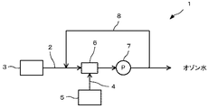
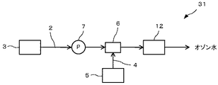
図1は、本発明の一実施形態であるオゾン水の製造装置を示したものである。このオゾン水の製造装置1は、純水配管2に純水を供給する純水供給手段3と、オゾンガス配管4にオゾンガスを供給するオゾンガス供給手段5と、純水配管2とオゾンガス配管4とに接続され、純水とオゾンガスとを混合してオゾン混合水とするエゼクタ6と、オゾン水を吸引、吐出して撹拌するポンプ7と、ポンプ7から吐出されたオゾン水の一部を、純水配管2に循環が可能なように設けられたバイパス流路8と、から構成されているものである。
(First embodiment)
Hereinafter, a first embodiment of the present invention will be described.
FIG. 1 shows an apparatus for producing ozone water according to an embodiment of the present invention. The ozone
本発明に用いる純水配管2及びオゾンガス配管4は、通常の配管を使用できるが、純水配管2は、途中で純水とオゾンガスの接触によりオゾン水を流通させるものであるため、配管自体又は配管表面をオゾン耐性に優れた部材、例えば、四フッ化物、純チタン、石英等で製造されているものであることが好ましい。また、本発明におけるオゾン水と接触する可能性のある配管は全て同様の部材を用いたものであることが好ましい。
As the
そして、本発明に用いる純水供給手段3は、純水製造装置等で製造した純水を純水配管2に流通させて、後述するエゼクタ6を介してオゾンガスを溶解しつつ、ポンプ7にまで供給するものであり、純水製造装置本体や製造した純水を貯留したタンクから純水配管2に流通させるようにしたポンプ等が挙げられる。
And the pure water supply means 3 used for this invention distribute | circulates the pure water manufactured with the pure water manufacturing apparatus etc. to the
オゾンガス供給手段5は、オゾナイザ等で製造したオゾンガスをオゾンガス配管4に流通させ、純水が供給される純水配管2にエゼクタ6を介してオゾンガスを供給するものであり、オゾナイザそのものが好適に挙げられる。
The ozone gas supply means 5 distributes ozone gas produced by an ozonizer or the like to the
次に、エゼクタ6は、純水とオゾンガスとを混合してオゾン混合水とするものであるが、例えば、ベンチュリ管状のエゼクタが挙げられ、この場合、純水がベンチュリ管内を高速流で通過する際にベンチュリ管の側面にあいたオゾンガス流入口が負圧となり、オゾンガスを泡として引き込むことにより、純水にオゾンガスが混合される。ベンチュリ管内部にはオゾンガス流入口の部分でより高速流になるように設計される。生成されたオゾン水は、次に説明するポンプにより吸引される。
Next, the
ポンプ7は、ダイヤフラムポンプ又はベローズポンプからなるものである。これらのポンプは、その表面がオゾン等の耐性に優れた樹脂、例えば、テトラフルオロエチレン/パーフルオロアルコキシエチレンの共重合体(PFA)、テトラフルオロエチレン/ヘキサフルオロプロピレンの共重合体(FEP)、ポリテトラフルオロエチレン(PTFE)等のフッ素樹脂で加工されたものを用いることが好ましい。表面を加工することで高濃度のオゾンを用いた場合でもポンプ自体がオゾンにより腐食されることがない。 The pump 7 is a diaphragm pump or a bellows pump. These pumps have a resin whose surface is excellent in resistance such as ozone, for example, a copolymer of tetrafluoroethylene / perfluoroalkoxyethylene (PFA), a copolymer of tetrafluoroethylene / hexafluoropropylene (FEP), It is preferable to use a material processed with a fluororesin such as polytetrafluoroethylene (PTFE). Even when high concentration ozone is used by processing the surface, the pump itself is not corroded by ozone.
また、このポンプ7は、吸引側にエゼクタ6が配設されており、エゼクタ6で混合されたオゾン混合水を吸引し、さらに撹拌混合して、純水にオゾンガスが溶解するのを促進させ、高濃度のオゾン水を含むオゾン混合水を吐出するものである。ここで、オゾン混合水とは、純水とオゾンガスとを混合することによりオゾンガスが純水中に溶解して製造されるオゾン水と一部余剰のオゾンガスとで構成されるものである。
Further, the pump 7 is provided with an
そして、このポンプ7は、液体と気体の混合量を適宜調整することができ、高濃度のオゾン水を製造しようとする場合にポンプ7の吸引側においてオゾンガスの供給量を多くして、エゼクタ6を介して多量のオゾンガスを純水中に混合することができるものである。この点において、回転容積型ポンプに比べ、その量比は顕著であり、高濃度のオゾン水を製造する本発明における必須の構成要素である。 The pump 7 can appropriately adjust the mixing amount of the liquid and gas. When producing high-concentration ozone water, the supply amount of ozone gas is increased on the suction side of the pump 7 so that the ejector 6 A large amount of ozone gas can be mixed in pure water via In this respect, the quantity ratio is remarkable as compared with the rotary positive displacement pump, which is an essential component in the present invention for producing high-concentration ozone water.
さらに、ダイヤフラムポンプ又はベローズポンプは、その構成が簡易で、汎用されているため安価に入手することができ、これらポンプを用いることによりオゾン水の製造を低コストに抑えるのに効果的でもある。 Furthermore, diaphragm pumps or bellows pumps are simple in structure and are widely used, so that they can be obtained at a low cost. Using these pumps is also effective in suppressing the production of ozone water at a low cost.
そして、このポンプ7により、オゾナイザからのオゾンガスを安定して発生させてオゾン水を効率的に製造することができるようになっている。すなわち、オゾナイザは、その原理として、対向した電極間に高周波高電圧を印加することで、電極の間で無声放電が発生し、供給した酸素ガスの一部をオゾンガスとしているが、当然のことながら、供給する酸素ガスは定常的に流したほうが、オゾンガスの発生が安定し、かつその濃度を高く保つことができ、オゾンガス流量に脈動があった場合、オゾンガス濃度は1割から、2割程度減少してしまう。 The pump 7 can efficiently produce ozone water by stably generating ozone gas from the ozonizer. That is, as a principle, the ozonizer generates a silent discharge between the electrodes by applying a high frequency high voltage between the electrodes facing each other, and naturally, part of the supplied oxygen gas is ozone gas. If the supplied oxygen gas is made to flow constantly, the generation of ozone gas is stable and the concentration can be kept high. If there is pulsation in the flow rate of ozone gas, the ozone gas concentration is reduced from 10% to 20%. Resulting in.
渦巻き式ポンプと比較してダイヤフラムポンプ又はベローズポンプは、その構造から、供給する流量に脈動を生じる。機種にもよるが、流量が多くなると、ポンプの内容量は増える分1分間当たりのストローク数(送液回数)は減ってしまい、脈動が増えることになる。脈動が生じるとオゾンガスが円滑に供給できない時間が長くなり、その影響でオゾナイザから発生するオゾンガス濃度が下がってしまい、ひいては製造されるオゾン水の濃度が上下して不安定になったり、オゾンガスが安定供給される場合と比べてオゾン濃度が低くなったりして、オゾン水を安定して製造することができない。 Compared with a spiral pump, a diaphragm pump or a bellows pump causes pulsation in the supplied flow rate because of its structure. Although depending on the model, when the flow rate increases, the number of strokes per minute (number of times of liquid feeding) decreases as the internal capacity of the pump increases, and pulsation increases. When pulsation occurs, the time during which ozone gas cannot be supplied smoothly becomes longer, and as a result, the concentration of ozone gas generated from the ozonizer decreases. Compared with the case where it is supplied, the ozone concentration becomes low, and ozone water cannot be produced stably.
そこで、本発明において設けられているバイパス流路8は、ポンプ7から吐出されたオゾン水の一部を、エゼクタ6の前段の純水配管2に循環が可能なように設けられており、このように、オゾン水を循環可能なようにバイパス流路8を設けることで、ポンプ7の動作に起因する装置内部での脈動が生じるのを抑制することができる。
Therefore, the
ここで脈動を抑制することにより、純水及びオゾンガスの供給、純水へのオゾンガスの溶解が円滑に行われ、オゾナイザから供給されるオゾンガスの濃度も安定するため、オゾン水中のオゾン濃度が安定し、かつ高濃度のオゾン水を効率的に製造することができる。 By suppressing the pulsation here, the supply of pure water and ozone gas, and the dissolution of ozone gas in pure water are performed smoothly, and the concentration of ozone gas supplied from the ozonizer is also stable, so the ozone concentration in ozone water is stable. In addition, high-concentration ozone water can be efficiently produced.
このとき、製造されたオゾン混合水はユースポイントへ供給されるようになっているが、そのユースポイントへオゾン混合水を送液する配管の途中には、バイパス流路8の入り口が設けられ、純水配管2にはバイパス流路8の出口が設けられており、オゾン混合水の一部が循環可能なように構成されている。
At this time, the produced ozone mixed water is supplied to the use point, but in the middle of the pipe for sending the ozone mixed water to the use point, an inlet of the
このようにバイパス流路8が設けられていることで、ポンプによる脈動をバイパス流路8に存在する気体等が吸収することができるため、オゾナイザにより供給されるオゾンガス濃度も安定にすることができ、ひいては製造されるオゾン水のオゾン濃度も安定するのである。
Since the
次に、オゾン水の製造装置1を用いたオゾン水の製造方法について説明する。
まず、純水配管2に純水供給手段3から純水を供給し、一方では、オゾンガス配管4にオゾンガス供給手段5からオゾンガスを供給する。
Next, the manufacturing method of ozone water using the ozone
First, pure water is supplied from the pure water supply means 3 to the
このとき供給する純水は、例えば、抵抗率が10MΩ・cm以上であるような純度のものが挙げられ、その目的に応じて適した純度の純水を使用するようにすればよい。半導体製造のレジスト剥離に使用する場合には、例えば、抵抗率が18MΩ・cm以上の超純水であることが好ましい。 The pure water supplied at this time includes, for example, a purity having a resistivity of 10 MΩ · cm or more, and pure water having a purity suitable for the purpose may be used. When used for resist stripping in semiconductor manufacturing, for example, ultrapure water having a resistivity of 18 MΩ · cm or more is preferable.
また、ここで供給されるオゾンガスはその濃度を適宜調節することができるが、オゾン濃度が40mg/L以上のオゾン水を製造するためにはオゾンガス濃度が150〜300g/m3であることが好ましく、その中でも200g/m3以上であることが特に好ましい。 The concentration of the ozone gas supplied here can be adjusted as appropriate, but the ozone gas concentration is preferably 150 to 300 g / m 3 in order to produce ozone water having an ozone concentration of 40 mg / L or more. Of these, 200 g / m 3 or more is particularly preferable.
このとき、純水とオゾンガスのそれぞれの供給流量は、高濃度オゾンガスの製造効率の観点から、純水:オゾンガスの体積比で1:0.5〜1:20の範囲であることが好ましく、1:0.5〜1:2であることがより好ましく、1:0.8〜1:1.2であることが特に好ましい。 At this time, the supply flow rates of pure water and ozone gas are preferably in the range of 1: 0.5 to 1:20 in terms of volume ratio of pure water: ozone gas from the viewpoint of production efficiency of high-concentration ozone gas. : 0.5 to 1: 2 is more preferable, and 1: 0.8 to 1: 1.2 is particularly preferable.
これら純水及びオゾンガスを配管中でエゼクタ6を介して接触させた後、ポンプ7により両者を吸引し、純水とオゾンガスとをポンプ内で十分に混合してオゾン混合水として吐出する。なお、ここでオゾン混合水は、上記したように、純水とオゾンガスとを混合することによりオゾンガスが純水中に溶解して製造されるオゾン水と一部余剰のオゾンガスとで構成されるものである。
After bringing these pure water and ozone gas into contact with each other through the
このときオゾン混合水は、ポンプ7で加圧されユースポイントに供給される。このとき、このポンプ7の後段にはポンプ7から吐出されたオゾン混合水の一部又は全部を、純水配管2に循環が可能なように設けられたバイパス流路8の入り口が設けられており、ポンプ7から吐出されたオゾン水を純水配管2に循環させる。この循環により、装置内部のオゾン水の脈動を抑えることができ、所定の濃度のオゾン水を安定して製造することができる。ただし、このバイパス流路8は、必ずしもオゾン水を循環させなくてもよく、バイパスが存在するだけでも、その流路内部に存在する気体等が装置内部のオゾン水の脈動を吸収して抑える働きをすることができる。
At this time, the ozone mixed water is pressurized by the pump 7 and supplied to the use point. At this time, an inlet of a
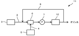
また、本発明のオゾン水の製造装置においては、さらに、気液分離手段を設けることが好ましく、例えば、図2に示したオゾン水製造装置11のように、図1に示したオゾン水製造装置1のポンプ7の後段に気液分離手段12を設けるようにしてオゾン水の製造装置を構成することが好ましい。
Moreover, in the ozone water manufacturing apparatus of this invention, it is preferable to provide a gas-liquid separation means, for example, the ozone water manufacturing apparatus shown in FIG. 1 like the ozone
この気液分離手段12は、ポンプ7から吐出されたオゾン混合水を収容するタンクと、タンク内部の圧力を調整する圧力調整手段を有しており、タンク内部の余剰のオゾンガスを外部に排出することにより、オゾンガスとオゾン水とを分離することができるようになっている。 This gas-liquid separating means 12 has a tank for storing the ozone mixed water discharged from the pump 7 and a pressure adjusting means for adjusting the pressure inside the tank, and discharges excess ozone gas inside the tank to the outside. Thus, the ozone gas and the ozone water can be separated.
この気液分離手段12としては、従来公知のものを使用することができ、例えば、遠心力を利用してオゾン水とオゾンガスとを分離するサイクロン式、気液二相流をバッフル板に衝突させるバッフル式、金網を用いて気液分離するデミスタ式等を挙げることができる。 As the gas-liquid separation means 12, a conventionally known one can be used. For example, a cyclone type that separates ozone water and ozone gas using centrifugal force, and a gas-liquid two-phase flow is caused to collide with a baffle plate. Examples thereof include a baffle type and a demister type that separates gas and liquid using a wire mesh.
このような構成とした場合、その後にユースポイントに供給されるオゾン水の濃度を安定したものとすることができ、例えば、タンクの内圧を大気圧より高く維持するようにすると、タンク中のオゾン水からオゾンが排気オゾンガス(気相)側に出て行くのを抑制して、オゾン水中のオゾン濃度を高いまま維持することができるようになり好ましい。 In such a configuration, it is possible to stabilize the concentration of ozone water that is subsequently supplied to the use point. For example, if the internal pressure of the tank is maintained higher than the atmospheric pressure, the ozone in the tank It is preferable because ozone can be prevented from exiting from the water to the exhaust ozone gas (gas phase) side, and the ozone concentration in the ozone water can be maintained high.
また、このタンクの内圧を利用してオゾン水を供給するようにすれば、ダイヤフラムポンプやベローズポンプで生じる脈動の影響をほとんど受けずにオゾン水を供給することもできる。 Further, if ozone water is supplied using the internal pressure of the tank, the ozone water can be supplied almost without being affected by the pulsation generated by the diaphragm pump or the bellows pump.
そして、オゾンガスを大気中に排気するときには、環境を汚染することがないように、大気中への放出前にオゾンガスを分解することが好ましく、オゾンガス分解を行なうものとしては、紫外線照射手段、触媒等の公知の手段を用いることができる。 And, when exhausting ozone gas into the atmosphere, it is preferable to decompose the ozone gas before releasing it into the atmosphere so as not to pollute the environment. Any known means can be used.
さらに、この気液分離手段12は、その後段にバイパス流路の入り口が設けられていることが好ましく、このようにすると、使用するオゾン水を効率よくユースポイントに供給できるとともに、バイパス流路により純水配管2に循環させることができ、循環させた場合には、そのオゾン水は純水と混合されるものの再度オゾンガスとの接触によりさらに高濃度のオゾン水を製造することもできる。
Furthermore, it is preferable that the gas-liquid separation means 12 is provided with an inlet of the bypass flow path at the subsequent stage. In this way, the ozone water to be used can be efficiently supplied to the use point, and the bypass flow path can be used. It can be circulated through the
なお、このときの気液分離手段12のタンクの内圧は、0.15〜0.5MPaの範囲とすることが好ましく、0.3〜0.5MPaであることがより好ましい。 In addition, it is preferable to make the internal pressure of the tank of the gas-liquid separation means 12 at this time into the range of 0.15-0.5 MPa, and it is more preferable that it is 0.3-0.5 MPa.
また、このタンクの内圧を利用し高濃度のオゾン水とし、この内圧を利用してオゾン水をユースポイントへと送液することもでき、さらに、この内圧でオゾン水を供給するようにすれば、ダイヤフラムポンプやベローズポンプで生じる脈動の影響をほとんどうけずにオゾン水を供給することが出来る。 It is also possible to use this tank's internal pressure to produce high-concentration ozone water and use this internal pressure to send ozone water to the point of use. Furthermore, if ozone water is supplied at this internal pressure, The ozone water can be supplied almost without being affected by the pulsation produced by the diaphragm pump or the bellows pump.
また、この実施形態において、純水配管2に、酸又は炭酸ガス等を少量添加してオゾン水のpHを下げるpH調整手段を設けてもよく、この場合、オゾン水を高濃度で維持し易くなる。そして、本実施形態のオゾン水の製造装置は循環配管8を有するため、系内に添加した酸又は炭酸ガスは結果として循環されるので、純水配管2ではなく、気液分離手段12のオゾン水が貯留するタンクに酸又は炭酸ガスを直接注入するようにしてもよい。
In this embodiment, the
(第2の実施形態)
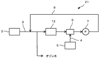
図3は、本発明の別の実施形態であるオゾン水の製造装置を示したものである。このオゾン水の製造装置21は、純水配管2に純水を供給する純水供給手段3と、オゾンガス配管4にオゾンガスを供給するオゾンガス供給手段5と、純水配管2とオゾンガス配管4とに接続され、純水とオゾンガスとを混合してオゾン混合水とするエゼクタ6と、オゾン混合水を吸引、吐出して撹拌するポンプ7と、ポンプ7から吐出されたオゾン混合水の全部を、純水配管に循環が可能なように設けられたバイパス流路8と、純水配管2のバイパス流路8との接続部の後段であって、エゼクタ6の前段に設けられた気液分離手段12と、純水配管2のバイパス流路8との接続部の後段であって、気液分離手段12の前段に設けられたオゾン水をユースポイントまで供給するオゾン水配管と、から構成されているものである。
(Second Embodiment)
FIG. 3 shows an apparatus for producing ozone water according to another embodiment of the present invention. The ozone
本実施形態では、図2で示したオゾン水の製造装置11とは、気液分離手段12の位置がエゼクタ6の前段に設けられ、ポンプ7で吐出されたオゾン混合水は、その全てがバイパス流路8により循環され、純水配管2に返送される点で異なるものである。そして、循環されたオゾン混合水は、純水供給手段3から供給される純水と混合され、純水配管2中を気液分離手段12まで送液されるようになっている。
In the present embodiment, the ozone
ここで、気液分離手段12により、先に説明しように、気液分離手段12のタンク内は所定の圧力になるように、オゾン混合水のオゾンガスが排出され、オゾンガスとオゾン水とを分離するものである。ここで得られたオゾン水は、さらにオゾンガスと混合され、より高濃度のオゾン水が製造されるように動作される。
Here, as described above, the gas-
そして、オゾン水はバイパス流路8により純水配管2に循環され、気液分離手段12に到達する前に、純水配管2の途中でユースポイントに導出されるようになっている。これは、所望のオゾン水が製造されるまで循環しながら操作を行うことができ、使用するタイミングでユースポイントまで導くようにすればよい。
The ozone water is circulated to the
また、ユースポイントまで導くオゾン水配管は、ポンプ7の後段であって、バイパス流路8により純水配管2へ循環される前にユースポイントに送液できるように設けることもでき、この場合、純水によりオゾン濃度が薄まらない点で好ましい。
In addition, the ozone water pipe leading to the use point can be provided after the pump 7 so that it can be sent to the use point before being circulated to the
(実施例1)
図2で説明した構成を有するオゾン水の製造装置を用い、供給するオゾンガス濃度を変動させながらオゾン水を製造した実施例を以下に示す。
Example 1
An embodiment in which ozone water is manufactured using the ozone water manufacturing apparatus having the configuration described in FIG. 2 while varying the concentration of ozone gas to be supplied is shown below.
純水供給手段3である超純水製造装置から水温24.5℃、抵抗率18MΩ・cm以上の水質の超純水を5L/分供給した。供給圧は、0.2MPaであった。この超純水には炭酸ガスを300mL/分で供給してpH4.5程度となるようにした。 Ultrapure water having a water temperature of 24.5 ° C. and a resistivity of 18 MΩ · cm or more was supplied at 5 L / min from the ultrapure water production apparatus as the pure water supply means 3. The supply pressure was 0.2 MPa. Carbon dioxide gas was supplied to the ultrapure water at 300 mL / min so as to have a pH of about 4.5.
また、オゾンガス供給手段5であるオゾナイザで発生させたオゾンガスを、オゾンガス配管4を通じて供給した。オゾナイザは、住友精密工業株式会社製の商品(型式:GR−RG)を用いて、酸素ガスを供給してオゾンガスを製造したものである。
Further, ozone gas generated by an ozonizer which is the ozone gas supply means 5 was supplied through an
また、純水とオゾンガスとを混合するのには、エゼクタ(東フロコーポレーション株式会社製、商品名:CF−EM−A03)を用い、ポンプとしてはベローズポンプ(株式会社IWAKI製、商品名:WD−10TTD)を用いた。気液分離手段のタンク内圧は0.4MPaとなるように制御し、この条件下で、ユースポイントに供給されたオゾン水濃度をオゾン水濃度計(堀場アドバンスドテクノ株式会社製、型式:CZ−300i)で調べた。 Moreover, in order to mix pure water and ozone gas, an ejector (product name: CF-EM-A03, manufactured by Toflo Corporation) is used, and a bellows pump (product name: WD, manufactured by IWAKI Corporation) is used as a pump. −10 TTD). The tank internal pressure of the gas-liquid separation means is controlled to be 0.4 MPa, and under this condition, the ozone water concentration supplied to the use point is determined by an ozone water concentration meter (manufactured by Horiba Advanced Techno Co., Ltd., model: CZ-300i). ).
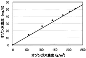
このとき供給されるオゾンガス濃度を0、57、105、142、179、204、224mg/m3として、製造されるオゾン水のオゾン濃度を測定したところ、それぞれ、0、14.1、26.3、34.4、41.5、46.7、50.7ppmであった。この結果を図4にグラフで示した。 The ozone gas concentration supplied at this time was measured as 0, 57, 105, 142, 179, 204, 224 mg / m 3 , and the ozone concentration of the produced ozone water was measured. 34.4, 41.5, 46.7, 50.7 ppm. The results are shown graphically in FIG.
(比較例1)
ベローズポンプの吐出側にエゼクタを用いた装置として、図6に示した構成のオゾン水製造装置により、純水及びオゾンガスの供給条件を同様にして、製造されるオゾン濃度を調べた。
(Comparative Example 1)
As an apparatus using an ejector on the discharge side of the bellows pump, the ozone concentration produced was examined using the ozone water production apparatus having the configuration shown in FIG. 6 under the same supply conditions of pure water and ozone gas.
このオゾン水製造装置は、純水をベローズポンプで吸引、吐出して、吐出された純水とオゾンガスとをエゼクタで混合するようになっており、混合されて得られたオゾン混合水は、気液分離手段に供給され、オゾン水がユースポイントに供給されるようになっている。また、バイパス流路は形成されていない。 This ozone water production apparatus sucks and discharges pure water using a bellows pump, and mixes the discharged pure water and ozone gas using an ejector. Supplyed to the liquid separation means, ozone water is supplied to the use point. Further, no bypass channel is formed.
実施例1と同様に、超純水製造装置から水温24.5℃、抵抗率18MΩ・cm以上の水質の超純水を5L/分供給した。超純水の供給圧は、0.2MPaとした。炭酸ガスは、超純水に300mL/分で供給した。 In the same manner as in Example 1, 5 L / min of ultrapure water having a water temperature of 24.5 ° C. and a resistivity of 18 MΩ · cm or more was supplied from the ultrapure water production apparatus. The supply pressure of ultrapure water was 0.2 MPa. Carbon dioxide gas was supplied to ultrapure water at 300 mL / min.
このとき供給されるオゾンガス濃度を0、67、88、106、155、192、215mg/m3として、製造されるオゾン水のオゾン濃度を測定したところ、それぞれ、0、12.0、15.0、19.0、25.1、31.1、33.1ppmであった。この結果を図7にグラフで示した。 The ozone gas concentration supplied at this time was set to 0, 67, 88, 106, 155, 192, 215 mg / m 3 , and the ozone concentration of the produced ozone water was measured to be 0, 12.0, 15.0, respectively. 19.0, 25.1, 31.1, 33.1 ppm. The results are shown graphically in FIG.
(実施例2)
図3で説明した構成を有するオゾン水の製造装置を用い、供給するオゾンガス濃度を変動させた実施例を以下に示す。
(Example 2)
An embodiment in which the ozone gas concentration to be supplied is varied using the apparatus for producing ozone water having the configuration described in FIG.
実施例1と同様に、超純水製造装置から水温24.5℃、抵抗率18MΩ・cm以上の水質の超純水を5L/分供給した。超純水の供給圧は、0.2MPaとした。炭酸ガスは、超純水に300mL/分で供給した。 In the same manner as in Example 1, 5 L / min of ultrapure water having a water temperature of 24.5 ° C. and a resistivity of 18 MΩ · cm or more was supplied from the ultrapure water production apparatus. The supply pressure of ultrapure water was 0.2 MPa. Carbon dioxide gas was supplied to ultrapure water at 300 mL / min.
このとき供給されるオゾンガス濃度を0、78、122、190、230、282mg/m3として、製造されるオゾン水のオゾン濃度を測定したところ、それぞれ、0、19.7、32.4、48.1、57.7、68.5ppmであった。この結果を図5にグラフで示した。 When the ozone gas concentration supplied at this time was set to 0, 78, 122, 190, 230, and 282 mg / m 3 , the ozone concentration of the produced ozone water was measured, and 0, 19.7, 32.4, and 48, respectively. 1, 57.7 and 68.5 ppm. The results are shown graphically in FIG.
また、この結果から、高濃度のオゾン水を得るためには、高濃度のオゾンガスと、多量の酸素ガス流量が必要であることがわかった。しかしながら、オゾンガス濃度は、市販製品であるオゾナイザの性能に依存し、上限に限界があるため、高濃度のオゾン水を製造するためには、必然的に、大量の酸素ガスを供給しなければならない。 Also, from this result, it was found that a high concentration ozone gas and a large amount of oxygen gas flow were required to obtain a high concentration ozone water. However, the ozone gas concentration depends on the performance of the commercial ozonizer and has an upper limit, so a large amount of oxygen gas must be supplied to produce high-concentration ozone water. .
したがって、従来式である渦巻きポンプを用いたオゾン水製造では、多量の酸素ガスを吸引できないため、本発明のような高濃度オゾン水を製造することは不可能であることが確認できた。 Accordingly, it has been confirmed that it is impossible to produce high-concentration ozone water as in the present invention because ozone water production using a conventional centrifugal pump cannot suck a large amount of oxygen gas.
以上の実施例及び比較例から、本発明のオゾン水製造装置及び方法は、ベローズポンプ又はダイヤフラムポンプを、エゼクタを吸引側に配設することで、純水とオゾンガスとを混合し、オゾン混合水を循環させる手段を用いることで、多量のオゾンガスを純水と接触させ混合することができ、かつ、オゾン混合水を循環可能なようにすることで装置内部での脈動も抑えられ、高濃度のオゾン水を安定して得ることが可能となった。 From the above examples and comparative examples, the ozone water production apparatus and method according to the present invention mixes pure water and ozone gas by disposing a bellows pump or a diaphragm pump on the suction side, thereby mixing ozone water. By using a means to circulate the water, a large amount of ozone gas can be brought into contact with pure water and mixed, and by allowing the ozone-mixed water to be circulated, pulsation inside the device can be suppressed and a high concentration can be achieved. It became possible to obtain ozone water stably.
1…オゾン水の製造装置、2…純水配管、3…純水供給手段、4…オゾンガス配管、5…オゾンガス供給手段、6…エゼクタ、7…ポンプ、8…バイパス流路、11…オゾン水の製造装置、12…気液分離手段、21,31…オゾン水の製造装置、32…ポンプ
DESCRIPTION OF
Claims (8)
オゾンガスをオゾンガス配管に流通させるオゾンガス供給手段と、
前記純水配管及び前記オゾンガス配管に接続され、純水とオゾンガスとを混合してオゾン混合水とするエゼクタと、
前記エゼクタが吸引側に配設され、前記オゾン混合水を吸引、吐出して撹拌する、ダイヤフラムポンプ又はベローズポンプからなるポンプと、
前記ポンプから吐出されたオゾン混合水の一部又は全部を、前記純水配管に循環が可能なように設けられたバイパス流路と、
を有することを特徴とするオゾン水の製造装置。 Pure water supply means for circulating pure water through the pure water pipe;
Ozone gas supply means for circulating ozone gas through an ozone gas pipe;
An ejector connected to the pure water pipe and the ozone gas pipe and mixing pure water and ozone gas to form ozone mixed water;
A pump comprising a diaphragm pump or a bellows pump, wherein the ejector is disposed on the suction side, and sucks, discharges and stirs the ozone mixed water;
A bypass passage provided so that a part or all of the ozone-mixed water discharged from the pump can be circulated in the pure water pipe;
An apparatus for producing ozone water, comprising:
オゾンガス配管にオゾンガスを流通させるオゾンガス供給工程と、
前記純水及び前記オゾンガスを、エゼクタにより混合してオゾン混合水とする気液混合工程と、
前記混合工程により得られたオゾン混合水を、ダイヤフラムポンプ又はベローズポンプからなるポンプにより吸引、吐出して撹拌する吸引撹拌工程と、
前記吸引撹拌工程により得られたオゾン混合水の一部又は全部を、前記純水配管に循環させる循環工程と、
を有することを特徴とするオゾン水の製造方法。 A deionized water supply process for distributing deionized water through deionized water piping;
An ozone gas supply process for circulating ozone gas in the ozone gas pipe;
A gas-liquid mixing step in which the pure water and the ozone gas are mixed by an ejector to form ozone mixed water;
A suction stirring step of sucking, discharging, and stirring the ozone mixed water obtained by the mixing step by a pump comprising a diaphragm pump or a bellows pump;
A circulation step of circulating part or all of the ozone mixed water obtained by the suction and stirring step to the pure water pipe;
A method for producing ozone water, comprising:
Priority Applications (1)
| Application Number | Priority Date | Filing Date | Title |
|---|---|---|---|
| JP2008335315A JP2010155754A (en) | 2008-12-26 | 2008-12-26 | Apparatus and method of manufacturing ozone water |
Applications Claiming Priority (1)
| Application Number | Priority Date | Filing Date | Title |
|---|---|---|---|
| JP2008335315A JP2010155754A (en) | 2008-12-26 | 2008-12-26 | Apparatus and method of manufacturing ozone water |
Publications (1)
| Publication Number | Publication Date |
|---|---|
| JP2010155754A true JP2010155754A (en) | 2010-07-15 |
Family
ID=42573965
Family Applications (1)
| Application Number | Title | Priority Date | Filing Date |
|---|---|---|---|
| JP2008335315A Pending JP2010155754A (en) | 2008-12-26 | 2008-12-26 | Apparatus and method of manufacturing ozone water |
Country Status (1)
| Country | Link |
|---|---|
| JP (1) | JP2010155754A (en) |
Cited By (4)
| Publication number | Priority date | Publication date | Assignee | Title |
|---|---|---|---|---|
| JP2012107270A (en) * | 2010-11-15 | 2012-06-07 | Citizen Finetech Miyota Co Ltd | Metal surface modification method by ozonized water |
| JP2020065988A (en) * | 2018-10-26 | 2020-04-30 | リオウ、フエイ タルングLiou, Huei Tarng | Gas dissolution system with double mixer |
| JP2020179372A (en) * | 2019-04-26 | 2020-11-05 | オルガノ株式会社 | Gas dissolution water manufacturing apparatus and method |
| CN114151730A (en) * | 2021-12-13 | 2022-03-08 | 拓荆科技股份有限公司 | Gas supply system providing gas switching and method of gas switching |
Citations (7)
| Publication number | Priority date | Publication date | Assignee | Title |
|---|---|---|---|---|
| JPS4968354A (en) * | 1972-11-02 | 1974-07-02 | ||
| JPH03217294A (en) * | 1990-01-19 | 1991-09-25 | Mitsubishi Heavy Ind Ltd | Production of ozonized water and ozonized ice |
| JPH0429798A (en) * | 1990-05-25 | 1992-01-31 | Fuso Kensetsu Kogyo Kk | Ozone contact method in water purifying treatment |
| JPH06142662A (en) * | 1992-11-02 | 1994-05-24 | Ishikawajima Harima Heavy Ind Co Ltd | Ozone water manufacturing device |
| WO1999054256A1 (en) * | 1998-04-20 | 1999-10-28 | Hoelter Heinrich | Device for introducing ozone into liquid media |
| JP2002166147A (en) * | 2000-12-04 | 2002-06-11 | Sasakura Engineering Co Ltd | Ozone water production apparatus |
| JP2007237113A (en) * | 2006-03-10 | 2007-09-20 | Sasakura Engineering Co Ltd | Apparatus for supplying ozone water |
-
2008
- 2008-12-26 JP JP2008335315A patent/JP2010155754A/en active Pending
Patent Citations (7)
| Publication number | Priority date | Publication date | Assignee | Title |
|---|---|---|---|---|
| JPS4968354A (en) * | 1972-11-02 | 1974-07-02 | ||
| JPH03217294A (en) * | 1990-01-19 | 1991-09-25 | Mitsubishi Heavy Ind Ltd | Production of ozonized water and ozonized ice |
| JPH0429798A (en) * | 1990-05-25 | 1992-01-31 | Fuso Kensetsu Kogyo Kk | Ozone contact method in water purifying treatment |
| JPH06142662A (en) * | 1992-11-02 | 1994-05-24 | Ishikawajima Harima Heavy Ind Co Ltd | Ozone water manufacturing device |
| WO1999054256A1 (en) * | 1998-04-20 | 1999-10-28 | Hoelter Heinrich | Device for introducing ozone into liquid media |
| JP2002166147A (en) * | 2000-12-04 | 2002-06-11 | Sasakura Engineering Co Ltd | Ozone water production apparatus |
| JP2007237113A (en) * | 2006-03-10 | 2007-09-20 | Sasakura Engineering Co Ltd | Apparatus for supplying ozone water |
Cited By (6)
| Publication number | Priority date | Publication date | Assignee | Title |
|---|---|---|---|---|
| JP2012107270A (en) * | 2010-11-15 | 2012-06-07 | Citizen Finetech Miyota Co Ltd | Metal surface modification method by ozonized water |
| JP2020065988A (en) * | 2018-10-26 | 2020-04-30 | リオウ、フエイ タルングLiou, Huei Tarng | Gas dissolution system with double mixer |
| JP2020179372A (en) * | 2019-04-26 | 2020-11-05 | オルガノ株式会社 | Gas dissolution water manufacturing apparatus and method |
| JP7292957B2 (en) | 2019-04-26 | 2023-06-19 | オルガノ株式会社 | Dissolved gas water production device and method |
| CN114151730A (en) * | 2021-12-13 | 2022-03-08 | 拓荆科技股份有限公司 | Gas supply system providing gas switching and method of gas switching |
| CN114151730B (en) * | 2021-12-13 | 2023-09-29 | 拓荆科技股份有限公司 | Gas supply system for providing gas switching and gas switching method |
Similar Documents
| Publication | Publication Date | Title |
|---|---|---|
| JP5020784B2 (en) | Ozone water production apparatus and production method | |
| JP6734621B2 (en) | Ozone water supply method and ozone water supply device | |
| JP5950790B2 (en) | Wastewater treatment method and system | |
| JP2010155754A (en) | Apparatus and method of manufacturing ozone water | |
| JP2009297588A (en) | Method of preparing heated ozone water | |
| JP2007326101A (en) | Ozone water treating method | |
| JP4108798B2 (en) | Ozone-containing ultrapure water supply method and ozone-containing ultrapure water supply device | |
| JP5412135B2 (en) | Ozone water supply device | |
| CN1974431A (en) | Water processing method containing surface active agent and processing device | |
| JP2003260341A (en) | Ozonized water supplying apparatus | |
| JP2010158672A (en) | Bubble generation method, bubble generation apparatus, and ozone water producing method | |
| JP2014117628A (en) | Circulation type method and apparatus for supplying ozone water | |
| JP2010199124A5 (en) | ||
| US10865130B2 (en) | Apparatus and method for producing alkaline water for cleaning electronic device | |
| JP2018051533A (en) | Apparatus and method for the production of hydrogen-containing water | |
| JP2005186067A (en) | Ozone-containing ultrapure water supply method and apparatus | |
| KR101634667B1 (en) | Apparatus for generating high density ozone gas dissolved water using electromagnetic field | |
| JP7204211B2 (en) | Batch-type microbubble liquid generator and generation method | |
| JP3748865B2 (en) | Deoxygenation method | |
| JPH08299971A (en) | Separating injection type ozone contact method | |
| JP2003164861A (en) | Ozone water deozonization system | |
| JP2003117570A (en) | Making method and making device for ozone water | |
| JP2009112975A (en) | Fine bubble generator and fine bubble generating method | |
| JP3509091B2 (en) | Ozone-containing ultrapure water supply device | |
| JP2013208555A (en) | Ozone dissolving device |
Legal Events
| Date | Code | Title | Description |
|---|---|---|---|
| A621 | Written request for application examination |
Free format text: JAPANESE INTERMEDIATE CODE: A621 Effective date: 20111207 |
|
| A977 | Report on retrieval |
Effective date: 20130220 Free format text: JAPANESE INTERMEDIATE CODE: A971007 |
|
| A131 | Notification of reasons for refusal |
Free format text: JAPANESE INTERMEDIATE CODE: A131 Effective date: 20130305 |
|
| A02 | Decision of refusal |
Free format text: JAPANESE INTERMEDIATE CODE: A02 Effective date: 20130625 |