JP2010094665A - Method for controlling emission of nitrous oxide associated with treatment of nitrogen-containing wastewater - Google Patents
Method for controlling emission of nitrous oxide associated with treatment of nitrogen-containing wastewater Download PDFInfo
- Publication number
- JP2010094665A JP2010094665A JP2009215314A JP2009215314A JP2010094665A JP 2010094665 A JP2010094665 A JP 2010094665A JP 2009215314 A JP2009215314 A JP 2009215314A JP 2009215314 A JP2009215314 A JP 2009215314A JP 2010094665 A JP2010094665 A JP 2010094665A
- Authority
- JP
- Japan
- Prior art keywords
- nitrification
- nitrous oxide
- nitrogen
- tank
- denitrification
- Prior art date
- Legal status (The legal status is an assumption and is not a legal conclusion. Google has not performed a legal analysis and makes no representation as to the accuracy of the status listed.)
- Granted
Links
- GQPLMRYTRLFLPF-UHFFFAOYSA-N Nitrous Oxide Chemical compound [O-][N+]#N GQPLMRYTRLFLPF-UHFFFAOYSA-N 0.000 title claims abstract description 132
- 238000000034 method Methods 0.000 title claims abstract description 67
- 239000001272 nitrous oxide Substances 0.000 title claims abstract description 65
- QJGQUHMNIGDVPM-UHFFFAOYSA-N nitrogen group Chemical group [N] QJGQUHMNIGDVPM-UHFFFAOYSA-N 0.000 title claims abstract description 33
- 239000002351 wastewater Substances 0.000 title claims abstract description 29
- 230000033116 oxidation-reduction process Effects 0.000 claims abstract description 34
- 229910021607 Silver chloride Inorganic materials 0.000 claims abstract description 30
- 229910052709 silver Inorganic materials 0.000 claims abstract description 30
- 239000004332 silver Substances 0.000 claims abstract description 30
- HKZLPVFGJNLROG-UHFFFAOYSA-M silver monochloride Chemical compound [Cl-].[Ag+] HKZLPVFGJNLROG-UHFFFAOYSA-M 0.000 claims abstract description 30
- 239000007788 liquid Substances 0.000 claims abstract description 19
- 238000006243 chemical reaction Methods 0.000 claims abstract description 17
- 239000006227 byproduct Substances 0.000 claims abstract description 11
- 230000000813 microbial effect Effects 0.000 claims abstract description 5
- 238000005273 aeration Methods 0.000 claims description 35
- IJGRMHOSHXDMSA-UHFFFAOYSA-N Atomic nitrogen Chemical compound N#N IJGRMHOSHXDMSA-UHFFFAOYSA-N 0.000 claims description 31
- 238000004065 wastewater treatment Methods 0.000 claims description 23
- 230000003247 decreasing effect Effects 0.000 claims description 15
- JVMRPSJZNHXORP-UHFFFAOYSA-N ON=O.ON=O.ON=O.N Chemical compound ON=O.ON=O.ON=O.N JVMRPSJZNHXORP-UHFFFAOYSA-N 0.000 claims description 14
- 229910052757 nitrogen Inorganic materials 0.000 claims description 14
- 239000000852 hydrogen donor Substances 0.000 claims description 10
- OAICVXFJPJFONN-UHFFFAOYSA-N Phosphorus Chemical compound [P] OAICVXFJPJFONN-UHFFFAOYSA-N 0.000 claims description 8
- 229910052698 phosphorus Inorganic materials 0.000 claims description 8
- 239000011574 phosphorus Substances 0.000 claims description 8
- 230000001629 suppression Effects 0.000 claims description 2
- 238000009792 diffusion process Methods 0.000 abstract description 5
- 239000007789 gas Substances 0.000 description 14
- XLYOFNOQVPJJNP-UHFFFAOYSA-N water Substances O XLYOFNOQVPJJNP-UHFFFAOYSA-N 0.000 description 12
- CURLTUGMZLYLDI-UHFFFAOYSA-N Carbon dioxide Chemical compound O=C=O CURLTUGMZLYLDI-UHFFFAOYSA-N 0.000 description 8
- 239000010802 sludge Substances 0.000 description 7
- XKMRRTOUMJRJIA-UHFFFAOYSA-N ammonia nh3 Chemical compound N.N XKMRRTOUMJRJIA-UHFFFAOYSA-N 0.000 description 6
- 241000894006 Bacteria Species 0.000 description 5
- MWUXSHHQAYIFBG-UHFFFAOYSA-N nitrogen oxide Inorganic materials O=[N] MWUXSHHQAYIFBG-UHFFFAOYSA-N 0.000 description 5
- 230000001737 promoting effect Effects 0.000 description 5
- QVGXLLKOCUKJST-UHFFFAOYSA-N atomic oxygen Chemical compound [O] QVGXLLKOCUKJST-UHFFFAOYSA-N 0.000 description 4
- 229910002092 carbon dioxide Inorganic materials 0.000 description 4
- 239000001569 carbon dioxide Substances 0.000 description 4
- 238000010586 diagram Methods 0.000 description 4
- 244000005700 microbiome Species 0.000 description 4
- 239000001301 oxygen Substances 0.000 description 4
- 229910052760 oxygen Inorganic materials 0.000 description 4
- 238000006722 reduction reaction Methods 0.000 description 4
- OKTJSMMVPCPJKN-UHFFFAOYSA-N Carbon Chemical compound [C] OKTJSMMVPCPJKN-UHFFFAOYSA-N 0.000 description 3
- OKKJLVBELUTLKV-UHFFFAOYSA-N Methanol Chemical compound OC OKKJLVBELUTLKV-UHFFFAOYSA-N 0.000 description 3
- MMDJDBSEMBIJBB-UHFFFAOYSA-N [O-][N+]([O-])=O.[O-][N+]([O-])=O.[O-][N+]([O-])=O.[NH6+3] Chemical compound [O-][N+]([O-])=O.[O-][N+]([O-])=O.[O-][N+]([O-])=O.[NH6+3] MMDJDBSEMBIJBB-UHFFFAOYSA-N 0.000 description 3
- 239000003463 adsorbent Substances 0.000 description 3
- 229910052799 carbon Inorganic materials 0.000 description 3
- 238000000354 decomposition reaction Methods 0.000 description 3
- 229910001873 dinitrogen Inorganic materials 0.000 description 3
- 239000000386 donor Substances 0.000 description 3
- 238000012544 monitoring process Methods 0.000 description 3
- 230000001546 nitrifying effect Effects 0.000 description 3
- 230000001603 reducing effect Effects 0.000 description 3
- 238000000926 separation method Methods 0.000 description 3
- 238000010792 warming Methods 0.000 description 3
- QGZKDVFQNNGYKY-UHFFFAOYSA-N Ammonia Chemical compound N QGZKDVFQNNGYKY-UHFFFAOYSA-N 0.000 description 2
- 230000007423 decrease Effects 0.000 description 2
- 230000000694 effects Effects 0.000 description 2
- 238000005259 measurement Methods 0.000 description 2
- 239000010865 sewage Substances 0.000 description 2
- 239000000126 substance Substances 0.000 description 2
- 239000002028 Biomass Substances 0.000 description 1
- 238000007696 Kjeldahl method Methods 0.000 description 1
- 238000010521 absorption reaction Methods 0.000 description 1
- 229910021529 ammonia Inorganic materials 0.000 description 1
- 239000003638 chemical reducing agent Substances 0.000 description 1
- 238000013461 design Methods 0.000 description 1
- 238000004821 distillation Methods 0.000 description 1
- 230000002349 favourable effect Effects 0.000 description 1
- 239000005431 greenhouse gas Substances 0.000 description 1
- 238000012423 maintenance Methods 0.000 description 1
- 238000005121 nitriding Methods 0.000 description 1
- 150000007524 organic acids Chemical class 0.000 description 1
- 238000007254 oxidation reaction Methods 0.000 description 1
- 230000001590 oxidative effect Effects 0.000 description 1
- 238000004062 sedimentation Methods 0.000 description 1
- 238000001179 sorption measurement Methods 0.000 description 1
- 238000011144 upstream manufacturing Methods 0.000 description 1
Images

Abstract
Description
本発明は、窒素含有排水の生物処理時に発生する亜酸化窒素が、大気中へ拡散することを抑制する技術に関するものである。 The present invention relates to a technique for suppressing diffusion of nitrous oxide generated during biological treatment of nitrogen-containing wastewater into the atmosphere.
下水等の窒素含有排水を生物学的に処理する際、反応副生成物として亜酸化窒素ガスが発生することが知られている。亜酸化窒素ガスは、二酸化炭素ガスの数百倍の温室効果を有する温室効果ガスであり、地球温暖化防止の観点から、大気中への排出抑制が求められている。 It is known that nitrous oxide gas is generated as a reaction byproduct when biologically treating nitrogen-containing wastewater such as sewage. Nitrous oxide gas is a greenhouse gas that has a greenhouse effect several hundred times that of carbon dioxide gas. From the viewpoint of preventing global warming, suppression of emission into the atmosphere is required.
生物学的な排水処理方法は、窒素含有排水中のアンモニア性窒素を酸化する硝化工程と、当該硝化液中に含まれる窒素酸化物を還元する脱窒工程とを有する(例えば、特許文献1)。前記生物学的な排水処理方法における亜酸化窒素ガスの生成メカニズムは、未だ明らかではないが、主に硝化工程におけるアンモニア性窒素の酸化反応の副生成物として生成するものと考えられる。 A biological wastewater treatment method includes a nitrification step of oxidizing ammonia nitrogen in nitrogen-containing wastewater, and a denitrification step of reducing nitrogen oxides contained in the nitrification solution (for example, Patent Document 1). . The generation mechanism of nitrous oxide gas in the biological wastewater treatment method is not yet clear, but is thought to be generated mainly as a byproduct of the oxidation reaction of ammoniacal nitrogen in the nitrification step.
ここで、硝化反応促進のためには、通常1.5mg/Lの溶存酸素が残存することが必要とされており(非特許文献1および非特許文献2)、硝化工程でブロアーからのエア送気により曝気を行い、前記溶存酸素量を確保している。しかし、曝気量が過剰となった場合には、硝化反応の副生成物として生成して硝化液中に溶存している亜酸化窒素が大気中に拡散してしまう問題があった。また、亜酸化窒素ガスを生物学的に処理する方法としては、亜酸化窒素ガスを吸着工程に導き、吸着剤に通して酸化二窒素を吸着させたのちに、該吸着剤又は該吸着剤から脱着した酸化二窒素含有ガス、又は該酸化二窒素含有ガスを吸収させた吸収液を、嫌気的条件下にある生物学的酸化二窒素分解工程に導入し、酸化二窒素を分解する技術が開示されている(特許文献2)。しかし、新たな工程の増設によらず、既存の排水処理設備をそのまま利用して、運転条件により亜酸化窒素が大気中に拡散することを防止する生物学的な排水処理技術への需要があった。 Here, in order to promote the nitrification reaction, it is usually required that 1.5 mg / L of dissolved oxygen remain (Non-Patent Document 1 and Non-Patent Document 2), and air is sent from the blower in the nitrification process. Aeration is performed by air to ensure the amount of dissolved oxygen. However, when the amount of aeration is excessive, there is a problem that nitrous oxide that is generated as a by-product of the nitrification reaction and dissolved in the nitrification solution diffuses into the atmosphere. In addition, as a method of biologically treating nitrous oxide gas, after introducing nitrous oxide gas into an adsorption process and passing nitrous oxide through an adsorbent, the adsorbent or the adsorbent is used. Disclosed is a technology for decomposing nitrous oxide by introducing a desorbed nitrous oxide-containing gas or an absorption liquid that has absorbed the nitrous oxide-containing gas into a biological nitrous oxide decomposition step under anaerobic conditions. (Patent Document 2). However, there is a demand for biological wastewater treatment technology that uses existing wastewater treatment equipment as it is and prevents nitrous oxide from diffusing into the atmosphere depending on operating conditions, regardless of the addition of new processes. It was.
なお、ブロアーの運転には大きな電力を必要とするため、過剰量の曝気は不必要な電力の消費に繋り二酸化炭素排出量が増加する問題があった。このように、過剰量の曝気は地球温暖化ガス排出抑制の観点から好ましくないため、生物学的な排水処理に際し、曝気量を最適に制御する技術への需要があった。 In addition, since the operation | movement of a blower requires big electric power, there existed a problem which excessive aeration leads to consumption of unnecessary electric power and the carbon dioxide emission amount increases. Thus, since an excessive amount of aeration is not preferable from the viewpoint of suppressing global warming gas emission, there has been a demand for a technique for optimally controlling the amount of aeration in biological wastewater treatment.
また、脱窒工程での還元反応の進行には、水素供与体となる有機炭素源の存在が必要となるが、過剰量の有機炭素源の添加はエネルギー効率の観点から好ましくない。したがって、生物学的な排水処理に際し、水素供与体となる有機炭素源の添加量を最適に制御する技術への需要があった。 In addition, the progress of the reduction reaction in the denitrification step requires the presence of an organic carbon source serving as a hydrogen donor, but the addition of an excessive amount of the organic carbon source is not preferable from the viewpoint of energy efficiency. Therefore, there has been a demand for a technique for optimally controlling the amount of organic carbon source added as a hydrogen donor during biological wastewater treatment.
本発明の目的は、前記の需要を満足し、硝化工程と脱窒工程を有する窒素含有排水の処理方法において、別途亜酸化窒素分解の為の新たな工程を設けることなく、硝化工程と脱窒工程の運転条件検討により亜酸化窒素の大気中への拡散を防止する技術を提供することである。また、当該技術は、硝化工程と脱窒工程の全行程において、排水処理効率を維持しつつ、地球温暖化ガス排出量の削減と、エネルギー効率の改善を図ることも目的とする。 An object of the present invention is to satisfy the above-mentioned demand, and in a method for treating nitrogen-containing wastewater having a nitrification step and a denitrification step, a nitrification step and a denitrification step can be performed without providing a separate new step for nitrous oxide decomposition. It is to provide a technique for preventing diffusion of nitrous oxide into the atmosphere by examining the operating conditions of the process. Another object of the technology is to reduce global warming gas emissions and improve energy efficiency while maintaining wastewater treatment efficiency in the entire nitrification process and denitrification process.
上記課題を解決するためになされた本発明に係る窒素含有排水処理に伴う亜酸化窒素排出抑制方法は、硝化工程と脱窒工程を有する窒素含有排水の処理方法において、脱窒槽の酸化還元電位を−300〜0mV(銀/塩化銀基準)に維持制御し、硝化槽の酸化還元電位を50〜200mV(銀/塩化銀基準)に維持制御し、硝化工程で副生成物として発生する亜酸化窒素を含有する硝化液を、脱窒工程に循環導入し、脱窒工程における微生物反応により、当該亜酸化窒素を還元することを特徴とするものである。 The method for suppressing nitrous oxide emission associated with the nitrogen-containing wastewater treatment according to the present invention, which has been made to solve the above problems, is a method for treating nitrogen-containing wastewater having a nitrification step and a denitrification step, wherein the oxidation-reduction potential of the denitrification tank is Nitrous oxide generated as a by-product in the nitrification process by maintaining and controlling at -300 to 0 mV (based on silver / silver chloride) and maintaining the oxidation-reduction potential of the nitrification tank at 50 to 200 mV (based on silver / silver chloride) A nitrifying solution containing is circulated and introduced into the denitrification step, and the nitrous oxide is reduced by a microbial reaction in the denitrification step.
請求項2記載の発明は、窒素含有排水処理に伴う亜酸化窒素排出抑制方法であって、硝化工程と脱窒工程を有する窒素含有排水の処理方法において、排水中に含有されるリンも合せて除去するために、脱窒槽の前段に嫌気槽を備え、嫌気槽の酸化還元電位を−400〜−200mV(銀/塩化銀基準)に維持制御し、脱窒槽の酸化還元電位を−200〜0mV(銀/塩化銀基準)に維持制御し、硝化槽の酸化還元電位を50〜200mV(銀/塩化銀基準)に維持制御し、硝化工程で副生成物として発生する亜酸化窒素を含有する硝化液を、脱窒工程に循環導入し、脱窒工程における微生物反応により、当該亜酸化窒素を還元することを特徴とするものである。
The invention according to
請求項3記載の発明は、請求項1または2記載の窒素含有排水処理に伴う亜酸化窒素排出抑制方法において、硝化槽の酸化還元電位制御は、曝気量の増減により行い、硝化槽中のアンモニア性窒素濃度が0〜1mg/Lとなるまで曝気を行うことを特徴とするものである。
The invention described in claim 3 is the method for suppressing nitrous oxide emission accompanying the treatment of nitrogen-containing waste water according to
請求項4記載の発明は、請求項1〜3の何れかに記載の窒素含有排水処理に伴う亜酸化窒素排出抑制方法において、硝化槽の酸化還元電位制御は、曝気量の増減により行い、硝化槽中の亜硝酸性窒素濃度が0〜2mg/Lとなるまで曝気を行うことを特徴とするものである。 According to a fourth aspect of the present invention, in the method for suppressing nitrous oxide emission associated with the nitrogen-containing wastewater treatment according to any one of the first to third aspects, the oxidation-reduction potential of the nitrification tank is controlled by increasing or decreasing the amount of aeration. Aeration is performed until the nitrite nitrogen concentration in the tank reaches 0 to 2 mg / L.
請求項5記載の発明は、請求項1または2記載の窒素含有排水処理に伴う亜酸化窒素排出抑制方法において、脱窒槽の酸化還元電位制御を、水素供与体の添加量の増減により行うことを特徴とするものである。 According to a fifth aspect of the present invention, in the method for suppressing nitrous oxide emission accompanying the treatment of nitrogen-containing wastewater according to the first or second aspect, the redox potential control of the denitrification tank is performed by increasing or decreasing the amount of addition of the hydrogen donor. It is a feature.
請求項6記載の発明は、請求項1または5に記載の窒素含有排水処理に伴う亜酸化窒素排出抑制方法において、脱窒槽の酸化還元電位制御を、硝化液の循環導入量の増減により行うことを特徴とするものである。
The invention according to
請求項7記載の発明は、請求項2記載の窒素含有排水処理に伴う亜酸化窒素排出抑制方法において、嫌気槽の酸化還元電位制御は、水素供与体の添加量の増減により行うことを特徴とするものである。
The invention according to
請求項8記載の発明は、請求項1〜3の何れかに記載の窒素含有排水処理に伴う亜酸化窒素排出抑制方法において、硝化槽の酸化還元電位制御は、曝気量の増減により行い、硝化槽中の亜硝酸性窒素濃度が0〜0.5mg/Lとなるまで曝気を行うことを特徴とするものである。
The invention according to
本発明の方法によれば、窒素含有排水の生物処理時に、硝化反応の副生成物として生じる亜酸化窒素の生物学的処理に関し、酸化還元電位が50〜200mV(銀/塩化銀基準)に維持制御された硝化槽からの硝化液を、酸化還元電位が0mV(銀/塩化銀基準)以下に維持制御された脱窒槽に導くことにより、亜酸化窒素を大気中に拡散させることなく、また、別途亜酸化窒素分解の為の工程を設ける手段によらずに、脱窒工程で亜酸化窒素を効果的に分解することが可能となった。なお、硝化槽と脱窒槽を各々前記範囲に制御することは、脱窒効率の観点からも好ましい。 According to the method of the present invention, the oxidation-reduction potential is maintained at 50 to 200 mV (silver / silver chloride standard) for biological treatment of nitrous oxide generated as a by-product of the nitrification reaction during biological treatment of nitrogen-containing wastewater. By directing the nitrification solution from the controlled nitrification tank to a denitrification tank whose oxidation-reduction potential is maintained at 0 mV (silver / silver chloride standard) or less, without nitrous oxide being diffused into the atmosphere, It has become possible to effectively decompose nitrous oxide in the denitrification step without using a means for separately providing a step for nitrous oxide decomposition. In addition, it is preferable from the viewpoint of denitrification efficiency to control the nitrification tank and the denitrification tank within the above ranges, respectively.
また被処理水の脱窒槽における酸化還元電位を、請求項1記載の発明では−300〜0mV(銀/塩化銀基準)、請求項2記載の発明では−200〜0mV(銀/塩化銀基準)と、高めに維持することにより、その後に硝化槽に導入された被処理水を、硝化反応促進に適した酸化還元電位である50〜200mV(銀/塩化銀基準)に上昇させる際に必要となる曝気量を低減させることができる。これにより、ブロワー運転による電力消費、及びこれに伴う二酸化炭素排出量が削減される。また、曝気量の低減により、硝化液中に溶存する亜酸化窒素が大気中への拡散リスクを低下させることができる。
The oxidation-reduction potential in the denitrification tank of the water to be treated is -300 to 0 mV (based on silver / silver chloride) in the invention described in claim 1, and -200 to 0 mV (based on silver / silver chloride) in the invention described in
請求項2記載の発明によれば、前記の効果を維持しつつ、排水中のリン成分も効果的に除去することができる。
According to invention of
請求項3記載の発明によれば、硝化槽中のアンモニア性窒素濃度を基準として、硝化反応の促進に最適量の曝気を行うことができる。これにより、硝化槽での過剰の曝気により、硝化液中に溶存する亜酸化窒素が大気中に拡散する問題を、効果的に抑制することができる。 According to the third aspect of the present invention, it is possible to perform aeration of an optimum amount for promoting the nitrification reaction on the basis of the ammoniacal nitrogen concentration in the nitrification tank. Thereby, the problem that the nitrous oxide dissolved in the nitrification liquid diffuses into the atmosphere due to excessive aeration in the nitrification tank can be effectively suppressed.
請求項4記載の発明によれば、亜硝酸性窒素濃度を基準として、硝化反応の促進に最適量の曝気を行うことができる。これにより、硝化槽での過剰の曝気により、硝化液中に溶存する亜酸化窒素が、大気中に拡散する問題を効果的に抑制することができる。請求項8記載の発明によれば、亜酸化窒素が大気中に拡散する問題を更に効果的に抑制することができる。 According to the fourth aspect of the present invention, it is possible to perform the aeration of the optimum amount for promoting the nitrification reaction on the basis of the nitrite nitrogen concentration. Thereby, the problem that the nitrous oxide dissolved in the nitrification liquid diffuses into the atmosphere due to excessive aeration in the nitrification tank can be effectively suppressed. According to the eighth aspect of the invention, the problem of nitrous oxide diffusing into the atmosphere can be more effectively suppressed.
請求項6記載の発明のように、排水中の窒素除去処理時に、脱窒槽の酸化還元電位制御を、硝化液の循環導入量の増減により行うことにより、水素供与体の添加量を抑制することができ、エネルギー効率の向上に資する。 As in the sixth aspect of the invention, the amount of hydrogen donor added is suppressed by controlling the oxidation-reduction potential of the denitrification tank by increasing or decreasing the circulation introduction amount of the nitrification liquid during the nitrogen removal treatment in the waste water. Can contribute to improving energy efficiency.
以下、図面を参照しつつ本発明に係る亜酸化窒素の生物学的処理方法を詳細に説明する。
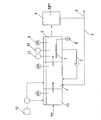
図1には、本発明の方法を適用する窒素含有排水処理装置の構成図を示している。窒素含有排水の生物学的処理工程では、図1に示すように、窒素含有排水が、嫌気性の脱窒槽1に流入してから好気性の硝化槽2に送られ、硝化槽2で処理された処理水の一部が循環路3を介して脱窒槽1に戻されると共に、残りが固液分離槽4に送られる。固液分離槽4では、処理水に同伴される活性汚泥を固液分離し、汚泥返送経路5を介して脱窒槽1に返送して脱窒槽1内の生物量を維持している。また、一部の汚泥は余剰汚泥として排出管6を介して装置外に排出される。
Hereinafter, the biological treatment method of nitrous oxide according to the present invention will be described in detail with reference to the drawings.
FIG. 1 shows a configuration diagram of a nitrogen-containing wastewater treatment apparatus to which the method of the present invention is applied. In the biological treatment process of nitrogen-containing wastewater, as shown in FIG. 1, the nitrogen-containing wastewater flows into the anaerobic denitrification tank 1, is then sent to the
硝化槽2では、ブロア8から供給されたエアが散気装置7により散気され、好気性条件下で活性汚泥中の好気性微生物である硝化菌により廃水中のアンモニア性窒素が亜硝酸性窒素や硝酸性窒素に硝化処理される。ここで、硝化槽2での硝化処理の反応副産物として亜酸化窒素ガスが生成する。
In the
(化1)
2NH4 ++3O2→2NO2 −+2H2O+4H+
2NO2 −+O2→2NO3 −
(Chemical formula 1)
2NH 4 + + 3O 2 → 2NO 2 - + 2H 2 O + 4H +
2NO 2 − + O 2 → 2NO 3 −
ここで、亜硝化窒素ガスが硝化槽2内の曝気に伴い大気中に拡散することを防止するためには、曝気量を抑制することが必要となる。一方、硝化反応促進の視点からは、通常、硝化槽末端の酸化還元電位は+100〜125mV以上が望ましいとされており、積極的な曝気が好適とされる。そこで、本発明では、硝化反応促進の指標として、アンモニア性窒素や亜硝酸性窒素濃度を測定して、硝化槽中のアンモニア性窒素濃度が0〜1mg/L、かつ、亜硝酸性窒素濃度が0〜2mg/Lとなるまで曝気を行って硝化反応の進行を確認しつつ、酸化還元電位を50〜200mV(銀/塩化銀基準)に維持制御することにより、過剰な曝気を抑制し、亜硝化窒素ガスが大気中に拡散することを防止している。なお、硝化槽中の亜硝酸性窒素濃度を0〜0.5mg/Lとすれば、より亜酸化窒素の排出量を低減することが可能になる。
Here, in order to prevent the nitrous nitrogen gas from diffusing into the atmosphere due to aeration in the
硝化槽2内における酸化還元電位の維持制御は、硝化槽2内に設置したORP計9、アンモニア性窒素測定計10、亜硝酸性窒素濃度測定計11による連続測定データのモニタリングを行いつつ、それぞれの値が前記制御範囲となるように、曝気量を調整することが好ましい。なお、曝気のための電力ブロワー運転による電力消費、及びこれに伴う二酸化炭素排出量削減の観点からは、酸化還元電位を50〜70mV(銀/塩化銀基準)に維持制御することが更に好ましい。
The maintenance control of the oxidation-reduction potential in the
硝化槽2からの硝化液が循環導入される脱窒槽1では、硝化槽2で生成された亜硝酸性窒素や硝酸性窒素が、原水中の有機物或いはメタノール等の電子供与体を還元剤として、嫌気性微生物である脱窒菌により脱窒処理されて窒素ガスに還元する。これにより原水中のアンモニア性窒素が除去される。一般に、硝化槽2で発生した亜酸化窒素含有ガスを、脱窒槽1の処理水中に直接導入して活性汚泥中の脱窒菌により生物学的に還元処理すると、含有ガス中に多く混在する酸素が嫌気性微生物である脱窒菌の還元反応を阻害する現象が生じるが、本発明では、前記のように硝化槽での曝気量を抑えて硝化液中の溶存酸素量を低水準に保ちつつ、脱窒槽の酸化還元電位を0mV(銀/塩化銀基準)以下に制御することにより、脱窒菌の還元反応を促進している。当該方法によれば、当該酸化還元電位下において、硝化液中に含有される亜硝酸性窒素や硝酸性窒素のみならず、硝化反応の副生成物として生じた亜酸化窒素も、嫌気性微生物による還元作用を受けて分解される。即ち、当該方法によれば、窒素含有排水の生物的処理工程において、別途亜酸化窒素処理工程を設けることなく、亜酸化窒素を分解処理することができる。
In the denitrification tank 1 in which the nitrification liquid from the
なお、酸化還元電位は電子供与体の添加と共に低下するが、−300mV以下に低下させた場合、その後に硝化槽2に導入された被処理水の酸化還元電位を前記の50〜200mV(銀/塩化銀基準)にまで上昇させるために多量の曝気が必要となり、多量の曝気は、硝化液中に含有される亜酸化窒素の大気中への拡散に繋がるため好ましくない。また、コスト面からも電子供与体の過剰投与は好ましくない。これらの観点からは、脱窒槽1の酸化還元電位を−100〜0mV(銀/塩化銀基準)に維持制御することが特に好ましい。当該制御は、硝化槽2内に設置したORP計のモニタリングを行いつつ、酸化還元電位が上記範囲となるように、水素供与体の添加、及び、硝化液の循環導入量の増減を行うことが好ましい。
The oxidation-reduction potential decreases with the addition of the electron donor. However, when the oxidation-reduction potential is decreased to −300 mV or less, the oxidation-reduction potential of the water to be treated introduced into the
図2には、本発明の方法を適用する窒素及びリン含有排水処理装置の構成図を示している。窒素及びリン含有排水の生物学的処理工程では、図2に示すように、脱窒槽1の前段に嫌気槽13が設けられ、リン放出を促している。本発明では、ORP計のモニタリングを行いつつ、酸化還元電位が−400〜−200mV(銀/塩化銀基準) となるように、水素供与体の添加を行う。当該範囲に制御を行うことにより、水素供与体の添加量を、リンの良好な放出のための最適量に抑制することができ、コスト抑制の観点から好ましい。嫌気槽13の酸化還元電位を−400〜−200mV(銀/塩化銀基準)に制御した場合、その後段に設けられた脱窒槽1に導入される処理液の酸化還元電位は−200mV以上に制御可能となる。脱窒工程および硝化工程に関しては、基本的に上記の窒素及含有排水処理の場合と同様である。なお、脱窒槽1における酸化還元電位の制御下限値が窒素及含有排水処理の場合(−300mV(銀/塩化銀基準)以上)と異なるのは、前記のように、脱窒槽1の前段にリン放出のための必要電位(−400〜−200mV(銀/塩化銀基準))を有する嫌気槽13を備えたことによるものであり、望ましくは−100〜0mV(銀/塩化銀基準)に維持制御することが特に好ましいことは、前記の窒素及含有排水処理の場合と同様である。
In FIG. 2, the block diagram of the waste water treatment equipment containing nitrogen and phosphorus to which the method of the present invention is applied is shown. In the biological treatment process of nitrogen and phosphorus containing wastewater, as shown in FIG. 2, an
下記の表1〜6には、都市下水最初沈殿池越流水(T−N濃度;30mg/L、NH4-N濃度;25mg/L)を、図1に示す装置を用いて、表1〜6の各条件で硝化液循環型生物学的脱窒を行った際の亜酸化窒素の大気中への放出量測定結果、及び処理水T−N濃度を示している。ここで、亜酸化窒素の大気中への放出量は捕集した曝気排ガス中の亜酸化窒素濃度をECD法にて測定した値から算出し、処理水T−N濃度は還元蒸留ケルダール法により測定した。なお、T−N濃度とは全窒素濃度をいう。 In Tables 1 to 6 below, the urban sewage first sedimentation basin overflow water (TN concentration: 30 mg / L, NH4-N concentration; 25 mg / L) is stored in Tables 1 to 6 using the apparatus shown in FIG. 3 shows the measurement results of the amount of nitrous oxide released into the atmosphere and the TN concentration of treated water when nitrifying liquid circulation-type biological denitrification is performed under each condition. Here, the amount of nitrous oxide released into the atmosphere is calculated from the value obtained by measuring the nitrous oxide concentration in the collected aerated exhaust gas by the ECD method, and the treated water TN concentration is measured by the reduced distillation Kjeldahl method. did. The TN concentration refers to the total nitrogen concentration.

上記の表1〜3に示すように、本発明によれば硝化工程と脱窒工程を有する窒素含有排水の処理方法において、脱窒槽の酸化還元電位を−300〜0mV(銀/塩化銀基準)に維持制御し、硝化槽の酸化還元電位を50〜200mV(銀/塩化銀基準)に維持制御することで処理水中のT−N濃度を低く維持しつつ、亜酸化窒素の排出量を低減することが可能になる。 As shown in Tables 1 to 3 above, according to the present invention, in the method for treating nitrogen-containing wastewater having a nitrification step and a denitrification step, the oxidation-reduction potential of the denitrification tank is -300 to 0 mV (based on silver / silver chloride). By maintaining and controlling the oxidation-reduction potential of the nitrification tank to 50 to 200 mV (silver / silver chloride standard), the TN concentration in the treated water is kept low and the nitrous oxide emission is reduced. It becomes possible.
なお、上記の表4〜6に示すように、硝化槽の酸化還元電位を50〜200mV(銀/塩化銀基準)に維持制御するに際し、硝化槽の酸化還元電位制御を曝気量の増減によって行い、具体的には、硝化槽中の亜硝酸性窒素濃度が0〜0.5mg/Lとなるまで曝気を行うことにより、亜酸化窒素の排出量を更に低減することが可能になる。 As shown in Tables 4 to 6 above, when maintaining the redox potential of the nitrification tank at 50 to 200 mV (silver / silver chloride standard), the redox potential of the nitrification tank is controlled by increasing or decreasing the aeration amount. Specifically, by performing aeration until the nitrite nitrogen concentration in the nitrification tank becomes 0 to 0.5 mg / L, it becomes possible to further reduce the discharge amount of nitrous oxide.
1 脱窒槽
2 硝化槽
3 循環路
4 固液分離槽
5 汚泥返送経路
6 排出管
7 散気装置
8 ブロア
9 ORP計
10 アンモニア性窒素計
11 亜硝酸性窒素計
12 有機酸タンク
13 嫌気槽
DESCRIPTION OF SYMBOLS 1
Claims (8)
脱窒槽の酸化還元電位を−300〜0mV(銀/塩化銀基準)に維持制御し、
硝化槽の酸化還元電位を50〜200mV(銀/塩化銀基準)に維持制御し、
硝化工程で副生成物として発生する亜酸化窒素を含有する硝化液を、脱窒工程に循環導入し、脱窒工程における微生物反応により、当該亜酸化窒素を還元することを特徴とする窒素含有排水処理に伴う亜酸化窒素排出抑制方法。 In a method for treating nitrogen-containing wastewater having a nitrification step and a denitrification step,
Maintaining and controlling the oxidation-reduction potential of the denitrification tank to -300 to 0 mV (silver / silver chloride standard)
Maintaining and controlling the redox potential of the nitrification tank to 50 to 200 mV (silver / silver chloride standard)
Nitrogen-containing wastewater characterized in that a nitrification liquid containing nitrous oxide generated as a by-product in the nitrification process is circulated and introduced into the denitrification process, and the nitrous oxide is reduced by a microbial reaction in the denitrification process. Nitrous oxide emission control method with treatment.
嫌気槽の酸化還元電位を−400〜−200mV(銀/塩化銀基準)に維持制御し、
脱窒槽の酸化還元電位を−200〜0mV(銀/塩化銀基準)に維持制御し、
硝化槽の酸化還元電位を50〜200mV(銀/塩化銀基準)に維持制御し、
硝化工程で副生成物として発生する亜酸化窒素を含有する硝化液を、脱窒工程に循環導入し、脱窒工程における微生物反応により、当該亜酸化窒素を還元することを特徴とする窒素含有排水処理に伴う亜酸化窒素排出抑制方法。 In the treatment method of nitrogen-containing wastewater having a nitrification step and a denitrification step, an anaerobic tank is provided in front of the denitrification tank in order to remove phosphorus contained in the wastewater together,
Maintain and control the redox potential of the anaerobic tank to -400 to -200 mV (silver / silver chloride standard)
Maintaining and controlling the redox potential of the denitrification tank to -200 to 0 mV (silver / silver chloride standard),
Maintaining and controlling the redox potential of the nitrification tank to 50 to 200 mV (silver / silver chloride standard)
Nitrogen-containing wastewater characterized in that a nitrification liquid containing nitrous oxide generated as a by-product in the nitrification process is circulated and introduced into the denitrification process, and the nitrous oxide is reduced by a microbial reaction in the denitrification process. Nitrous oxide emission control method with treatment.
水素供与体の添加量の増減
により行うことを特徴とする請求項1または2記載の窒素含有排水処理に伴う亜酸化窒素排出抑制方法。 Control the redox potential of the denitrification tank,
The method for suppressing nitrous oxide emission accompanying nitrogen-containing wastewater treatment according to claim 1 or 2, wherein the method is carried out by increasing or decreasing the amount of hydrogen donor added.
硝化液の循環導入量の増減
により行うことを特徴とする請求項1または5に記載の窒素含有排水処理に伴う亜酸化窒素排出抑制方法。 Control the redox potential of the denitrification tank,
6. The method for suppressing nitrous oxide emissions associated with nitrogen-containing wastewater treatment according to claim 1 or 5, wherein the method is carried out by increasing or decreasing the circulation introduction amount of the nitrification liquid.
水素供与体の添加量の増減
により行うことを特徴とする請求項2記載の窒素含有排水処理に伴う亜酸化窒素排出抑制方法。 The redox potential control of the anaerobic tank is
The method for suppressing nitrous oxide emission associated with nitrogen-containing wastewater treatment according to claim 2, wherein the method is carried out by increasing or decreasing the amount of hydrogen donor added.
Priority Applications (1)
| Application Number | Priority Date | Filing Date | Title |
|---|---|---|---|
| JP2009215314A JP5424789B2 (en) | 2008-09-19 | 2009-09-17 | Nitrous oxide emission control method for nitrogen-containing wastewater treatment |
Applications Claiming Priority (3)
| Application Number | Priority Date | Filing Date | Title |
|---|---|---|---|
| JP2008240177 | 2008-09-19 | ||
| JP2008240177 | 2008-09-19 | ||
| JP2009215314A JP5424789B2 (en) | 2008-09-19 | 2009-09-17 | Nitrous oxide emission control method for nitrogen-containing wastewater treatment |
Publications (2)
| Publication Number | Publication Date |
|---|---|
| JP2010094665A true JP2010094665A (en) | 2010-04-30 |
| JP5424789B2 JP5424789B2 (en) | 2014-02-26 |
Family
ID=42256729
Family Applications (1)
| Application Number | Title | Priority Date | Filing Date |
|---|---|---|---|
| JP2009215314A Active JP5424789B2 (en) | 2008-09-19 | 2009-09-17 | Nitrous oxide emission control method for nitrogen-containing wastewater treatment |
Country Status (1)
| Country | Link |
|---|---|
| JP (1) | JP5424789B2 (en) |
Cited By (9)
| Publication number | Priority date | Publication date | Assignee | Title |
|---|---|---|---|---|
| JP2011104585A (en) * | 2009-10-20 | 2011-06-02 | Metawater Co Ltd | Wastewater treatment method and wastewater treatment apparatus |
| JP2011110501A (en) * | 2009-11-27 | 2011-06-09 | Hitachi Ltd | Water treatment equipment |
| JP2011245359A (en) * | 2010-05-24 | 2011-12-08 | Hitachi Ltd | Sewage treatment apparatus |
| JP2012106198A (en) * | 2010-11-18 | 2012-06-07 | Toshiba Corp | Biological wastewater treatment apparatus |
| JP2012143727A (en) * | 2011-01-14 | 2012-08-02 | Hitachi Ltd | Water treatment apparatus |
| JP2012148217A (en) * | 2011-01-17 | 2012-08-09 | Toshiba Corp | Biological treatment method of wastewater, and wastewater treatment apparatus |
| JP2012228646A (en) * | 2011-04-26 | 2012-11-22 | Hitachi Ltd | Biological water treating apparatus |
| JP2013121586A (en) * | 2011-11-08 | 2013-06-20 | Toshiba Corp | Method and device for membrane separation activated sludge treatment |
| WO2023095399A1 (en) * | 2021-11-29 | 2023-06-01 | メタウォーター株式会社 | Biological treatment method and biological treatment system |
Citations (25)
| Publication number | Priority date | Publication date | Assignee | Title |
|---|---|---|---|---|
| JPS50147154A (en) * | 1974-05-17 | 1975-11-26 | ||
| JPS5120072A (en) * | 1974-08-12 | 1976-02-17 | Mitsubishi Heavy Ind Ltd | CHITSUSOSANKABUTSUOGANJUSURU EKITAINO DATSUCHITSUSOSHORIHOHO OYOBI SONOSOCHI |
| JPS55155797A (en) * | 1979-05-24 | 1980-12-04 | Agency Of Ind Science & Technol | Preventing method of n2o gas in biological denitrification treatment |
| JPH04180897A (en) * | 1990-11-13 | 1992-06-29 | Osaka Gas Co Ltd | Fixed bed type denitrifying method |
| JPH05154495A (en) * | 1991-12-03 | 1993-06-22 | Ngk Insulators Ltd | Method for nitrifying and denitrifying organic waste water |
| JPH06190241A (en) * | 1991-03-06 | 1994-07-12 | Ebara Infilco Co Ltd | Method and apparatus for biological treatment of dinitrogen oxide |
| JPH1043787A (en) * | 1996-07-31 | 1998-02-17 | Meidensha Corp | Device for simulating amount of nitrous oxide of activated sludge method |
| JPH10128389A (en) * | 1996-11-01 | 1998-05-19 | Hitachi Plant Eng & Constr Co Ltd | Method and apparatus for waste water treatment |
| JPH10180292A (en) * | 1996-12-24 | 1998-07-07 | Hitachi Plant Eng & Constr Co Ltd | Method of removing nitrogen from waste water and device therefor |
| JPH11156387A (en) * | 1997-11-21 | 1999-06-15 | Nishihara Environ Sanit Res Corp | Wastewater treatment apparatus |
| JP2000246055A (en) * | 1999-03-04 | 2000-09-12 | Hitachi Plant Eng & Constr Co Ltd | Method and apparatus for biologically treating nitrous oxide gas |
| JP2000279752A (en) * | 1999-03-30 | 2000-10-10 | Mitsubishi Heavy Ind Ltd | Nitrous oxide adsorbent, adsorption tower and waste water treatment |
| JP2002011495A (en) * | 2000-06-29 | 2002-01-15 | Nippon Steel Corp | Method for removing nitrogen and phosphor from wastewater |
| JP2002204926A (en) * | 2001-01-12 | 2002-07-23 | Kurabo Ind Ltd | Method for removing nitrous oxide in gas and system for removing it |
| JP2003053384A (en) * | 2001-08-23 | 2003-02-25 | Nippon Steel Corp | Method for removing nitrogen and phosphorus from waste water and facility therefor |
| JP2004230338A (en) * | 2003-01-31 | 2004-08-19 | Nippon Steel Corp | Method for removing ammonia nitrogen compound from waste water |
| JP2006136820A (en) * | 2004-11-12 | 2006-06-01 | Nippon Steel Corp | Method for removing phosphorus and/or nitrogen from sewage |
| JP2007075821A (en) * | 2006-12-22 | 2007-03-29 | Hitachi Plant Technologies Ltd | Biological treatment process and device of nitrous oxide gas |
| JP2007136298A (en) * | 2005-11-16 | 2007-06-07 | Nippon Steel Corp | Removal method of nitrogen and phosphorus from sewage, and removal apparatus |
| JP2007244949A (en) * | 2006-03-14 | 2007-09-27 | Tohoku Univ | Control procedure of nitrification process indexed by nitrous oxide |
| JP2008012425A (en) * | 2006-07-05 | 2008-01-24 | Nippon Steel Corp | Method and apparatus for removing phosphorus and nitrogen from sewage |
| JP2010000480A (en) * | 2008-06-23 | 2010-01-07 | Osaka City | Effective denitrification method for organic raw water |
| JP2010017639A (en) * | 2008-07-10 | 2010-01-28 | Metawater Co Ltd | Organic raw water denitrification method by control of nitrite-type nitrification |
| JP2010110706A (en) * | 2008-11-07 | 2010-05-20 | Obihiro Univ Of Agriculture & Veterinary Medicine | System and method for treating organic waste |
| JP2010269254A (en) * | 2009-05-22 | 2010-12-02 | Hitachi Ltd | Water treatment equipment |
-
2009
- 2009-09-17 JP JP2009215314A patent/JP5424789B2/en active Active
Patent Citations (25)
| Publication number | Priority date | Publication date | Assignee | Title |
|---|---|---|---|---|
| JPS50147154A (en) * | 1974-05-17 | 1975-11-26 | ||
| JPS5120072A (en) * | 1974-08-12 | 1976-02-17 | Mitsubishi Heavy Ind Ltd | CHITSUSOSANKABUTSUOGANJUSURU EKITAINO DATSUCHITSUSOSHORIHOHO OYOBI SONOSOCHI |
| JPS55155797A (en) * | 1979-05-24 | 1980-12-04 | Agency Of Ind Science & Technol | Preventing method of n2o gas in biological denitrification treatment |
| JPH04180897A (en) * | 1990-11-13 | 1992-06-29 | Osaka Gas Co Ltd | Fixed bed type denitrifying method |
| JPH06190241A (en) * | 1991-03-06 | 1994-07-12 | Ebara Infilco Co Ltd | Method and apparatus for biological treatment of dinitrogen oxide |
| JPH05154495A (en) * | 1991-12-03 | 1993-06-22 | Ngk Insulators Ltd | Method for nitrifying and denitrifying organic waste water |
| JPH1043787A (en) * | 1996-07-31 | 1998-02-17 | Meidensha Corp | Device for simulating amount of nitrous oxide of activated sludge method |
| JPH10128389A (en) * | 1996-11-01 | 1998-05-19 | Hitachi Plant Eng & Constr Co Ltd | Method and apparatus for waste water treatment |
| JPH10180292A (en) * | 1996-12-24 | 1998-07-07 | Hitachi Plant Eng & Constr Co Ltd | Method of removing nitrogen from waste water and device therefor |
| JPH11156387A (en) * | 1997-11-21 | 1999-06-15 | Nishihara Environ Sanit Res Corp | Wastewater treatment apparatus |
| JP2000246055A (en) * | 1999-03-04 | 2000-09-12 | Hitachi Plant Eng & Constr Co Ltd | Method and apparatus for biologically treating nitrous oxide gas |
| JP2000279752A (en) * | 1999-03-30 | 2000-10-10 | Mitsubishi Heavy Ind Ltd | Nitrous oxide adsorbent, adsorption tower and waste water treatment |
| JP2002011495A (en) * | 2000-06-29 | 2002-01-15 | Nippon Steel Corp | Method for removing nitrogen and phosphor from wastewater |
| JP2002204926A (en) * | 2001-01-12 | 2002-07-23 | Kurabo Ind Ltd | Method for removing nitrous oxide in gas and system for removing it |
| JP2003053384A (en) * | 2001-08-23 | 2003-02-25 | Nippon Steel Corp | Method for removing nitrogen and phosphorus from waste water and facility therefor |
| JP2004230338A (en) * | 2003-01-31 | 2004-08-19 | Nippon Steel Corp | Method for removing ammonia nitrogen compound from waste water |
| JP2006136820A (en) * | 2004-11-12 | 2006-06-01 | Nippon Steel Corp | Method for removing phosphorus and/or nitrogen from sewage |
| JP2007136298A (en) * | 2005-11-16 | 2007-06-07 | Nippon Steel Corp | Removal method of nitrogen and phosphorus from sewage, and removal apparatus |
| JP2007244949A (en) * | 2006-03-14 | 2007-09-27 | Tohoku Univ | Control procedure of nitrification process indexed by nitrous oxide |
| JP2008012425A (en) * | 2006-07-05 | 2008-01-24 | Nippon Steel Corp | Method and apparatus for removing phosphorus and nitrogen from sewage |
| JP2007075821A (en) * | 2006-12-22 | 2007-03-29 | Hitachi Plant Technologies Ltd | Biological treatment process and device of nitrous oxide gas |
| JP2010000480A (en) * | 2008-06-23 | 2010-01-07 | Osaka City | Effective denitrification method for organic raw water |
| JP2010017639A (en) * | 2008-07-10 | 2010-01-28 | Metawater Co Ltd | Organic raw water denitrification method by control of nitrite-type nitrification |
| JP2010110706A (en) * | 2008-11-07 | 2010-05-20 | Obihiro Univ Of Agriculture & Veterinary Medicine | System and method for treating organic waste |
| JP2010269254A (en) * | 2009-05-22 | 2010-12-02 | Hitachi Ltd | Water treatment equipment |
Cited By (9)
| Publication number | Priority date | Publication date | Assignee | Title |
|---|---|---|---|---|
| JP2011104585A (en) * | 2009-10-20 | 2011-06-02 | Metawater Co Ltd | Wastewater treatment method and wastewater treatment apparatus |
| JP2011110501A (en) * | 2009-11-27 | 2011-06-09 | Hitachi Ltd | Water treatment equipment |
| JP2011245359A (en) * | 2010-05-24 | 2011-12-08 | Hitachi Ltd | Sewage treatment apparatus |
| JP2012106198A (en) * | 2010-11-18 | 2012-06-07 | Toshiba Corp | Biological wastewater treatment apparatus |
| JP2012143727A (en) * | 2011-01-14 | 2012-08-02 | Hitachi Ltd | Water treatment apparatus |
| JP2012148217A (en) * | 2011-01-17 | 2012-08-09 | Toshiba Corp | Biological treatment method of wastewater, and wastewater treatment apparatus |
| JP2012228646A (en) * | 2011-04-26 | 2012-11-22 | Hitachi Ltd | Biological water treating apparatus |
| JP2013121586A (en) * | 2011-11-08 | 2013-06-20 | Toshiba Corp | Method and device for membrane separation activated sludge treatment |
| WO2023095399A1 (en) * | 2021-11-29 | 2023-06-01 | メタウォーター株式会社 | Biological treatment method and biological treatment system |
Also Published As
| Publication number | Publication date |
|---|---|
| JP5424789B2 (en) | 2014-02-26 |
Similar Documents
| Publication | Publication Date | Title |
|---|---|---|
| JP5424789B2 (en) | Nitrous oxide emission control method for nitrogen-containing wastewater treatment | |
| TWI386374B (en) | System and method for treating waste water containing ammonia | |
| JP5717188B2 (en) | Waste water treatment method and waste water treatment equipment | |
| JP5733785B2 (en) | Waste water treatment method and waste water treatment equipment | |
| JP5006845B2 (en) | Method for suppressing generation of nitrous oxide | |
| TWI449675B (en) | System and method for treating waste water containing ammonia | |
| JP5100091B2 (en) | Water treatment method | |
| TWI403467B (en) | Treatment device for drainage containing organic sulfur compounds | |
| JP2010063987A (en) | Waste water treatment device and treatment method | |
| Xiuhong et al. | Nitrous oxide production during nitrogen removal from domestic wastewater in lab-scale sequencing batch reactor | |
| JP4734996B2 (en) | Biological treatment method and apparatus for nitrogen-containing water | |
| JP2007125484A (en) | Nitrogen-containing wastewater treatment method | |
| CN108585199A (en) | One kind is by introducing AMX(Anammox)Bacterium strengthens the integrated apparatus and method of A/O technique deep denitrifications | |
| JP2014104416A (en) | Water treatment apparatus and water treatment method | |
| JP2000308900A (en) | Treatment of ammonia-containing waste water | |
| JP5656656B2 (en) | Water treatment equipment | |
| KR20110027457A (en) | Method for treating wastewater using nitrification reaction in sequencing batch reactor | |
| JP5812277B2 (en) | Nitrogen removal method | |
| JP5782415B2 (en) | Method and apparatus for treating water to be treated | |
| JP2001070747A (en) | Method and apparatus for treating nitrogen compound- containing waste gas | |
| KR20100083223A (en) | Method for high class treatment of wastewater using gas permeable membrane-attached biofilm | |
| JP2003094096A (en) | Method for treating organic waste, apparatus therefor, and sludge | |
| JP7050204B1 (en) | Wastewater treatment equipment and wastewater treatment method for wastewater containing high-concentration organic matter | |
| JP5782416B2 (en) | Method and apparatus for treating water to be treated | |
| JPH09290290A (en) | Treatment of coke-oven gas liquor |
Legal Events
| Date | Code | Title | Description |
|---|---|---|---|
| A621 | Written request for application examination |
Free format text: JAPANESE INTERMEDIATE CODE: A621 Effective date: 20120515 |
|
| A977 | Report on retrieval |
Free format text: JAPANESE INTERMEDIATE CODE: A971007 Effective date: 20121212 |
|
| A131 | Notification of reasons for refusal |
Free format text: JAPANESE INTERMEDIATE CODE: A131 Effective date: 20121214 |
|
| A521 | Request for written amendment filed |
Free format text: JAPANESE INTERMEDIATE CODE: A523 Effective date: 20130208 |
|
| A131 | Notification of reasons for refusal |
Free format text: JAPANESE INTERMEDIATE CODE: A131 Effective date: 20130301 |
|
| A521 | Request for written amendment filed |
Free format text: JAPANESE INTERMEDIATE CODE: A523 Effective date: 20130425 |
|
| TRDD | Decision of grant or rejection written | ||
| A01 | Written decision to grant a patent or to grant a registration (utility model) |
Free format text: JAPANESE INTERMEDIATE CODE: A01 Effective date: 20131108 |
|
| A61 | First payment of annual fees (during grant procedure) |
Free format text: JAPANESE INTERMEDIATE CODE: A61 Effective date: 20131126 |
|
| R150 | Certificate of patent or registration of utility model |
Free format text: JAPANESE INTERMEDIATE CODE: R150 Ref document number: 5424789 Country of ref document: JP Free format text: JAPANESE INTERMEDIATE CODE: R150 |
|
| R250 | Receipt of annual fees |
Free format text: JAPANESE INTERMEDIATE CODE: R250 |
|
| R250 | Receipt of annual fees |
Free format text: JAPANESE INTERMEDIATE CODE: R250 |
|
| R250 | Receipt of annual fees |
Free format text: JAPANESE INTERMEDIATE CODE: R250 |
|
| R250 | Receipt of annual fees |
Free format text: JAPANESE INTERMEDIATE CODE: R250 |