JP2010000480A - Effective denitrification method for organic raw water - Google Patents
Effective denitrification method for organic raw water Download PDFInfo
- Publication number
- JP2010000480A JP2010000480A JP2008163393A JP2008163393A JP2010000480A JP 2010000480 A JP2010000480 A JP 2010000480A JP 2008163393 A JP2008163393 A JP 2008163393A JP 2008163393 A JP2008163393 A JP 2008163393A JP 2010000480 A JP2010000480 A JP 2010000480A
- Authority
- JP
- Japan
- Prior art keywords
- nitrogen
- denitrification
- nitrification
- nitrite
- tank
- Prior art date
- Legal status (The legal status is an assumption and is not a legal conclusion. Google has not performed a legal analysis and makes no representation as to the accuracy of the status listed.)
- Granted
Links
Images
Landscapes
- Purification Treatments By Anaerobic Or Anaerobic And Aerobic Bacteria Or Animals (AREA)
Abstract
Description
本発明は効率的な有機性原水の脱窒方法に関するものである。 The present invention relates to an efficient method for denitrifying organic raw water.
従来、窒素含有液の脱窒方法としては、アンモニア性窒素をアンモニア酸化細菌の働きにより亜硝酸性窒素に酸化し、さらに亜硝酸性窒素を亜硝酸酸化細菌により硝酸性窒素に酸化する硝化工程と、これらの亜硝酸性窒素および硝酸性窒素を従属栄養細菌である脱窒細菌によりメタノール等の有機物を電子供与体として利用して窒素ガスにまで転換する脱窒工程との2段階の生物反応を経る生物学的硝化脱窒法が一般的であった。 Conventionally, as a method for denitrifying a nitrogen-containing liquid, there is a nitrification process in which ammonia nitrogen is oxidized to nitrite nitrogen by the action of ammonia oxidizing bacteria, and nitrite nitrogen is oxidized to nitrate nitrogen by nitrite oxidizing bacteria. , A two-stage biological reaction with a denitrification process in which these nitrite nitrogen and nitrate nitrogen are converted to nitrogen gas by using organic matter such as methanol as an electron donor by denitrifying bacteria which are heterotrophic bacteria. Biological nitrification and denitrification methods are common.
しかし、このような従属栄養細菌を利用する硝化脱窒処理では、アンモニア性窒素が亜硝酸を経て硝酸性窒素になるまで硝化するため、多くの曝気動力が必要となる欠点があった。 However, the nitrification / denitrification treatment using such heterotrophic bacteria has a drawback that a large amount of aeration power is required because ammonia nitrogen is nitrified until it becomes nitrate nitrogen via nitrous acid.
前記欠点を克服する手段として、アンモニア性窒素の一部を残存させる亜硝酸型硝化工程と、嫌気条件下でアンモニア性窒素を電子供与体、亜硝酸性窒素を電子受容体として両者を反応させ、窒素ガスを生成させる脱窒工程とからなる脱窒方法が開示されている(特許文献1)。 As means for overcoming the drawbacks, a nitrite-type nitrification step for leaving a part of ammonia nitrogen, and reacting both ammoniacal nitrogen as an electron donor and nitrite nitrogen as an electron acceptor under anaerobic conditions, A denitrification method including a denitrification step for generating nitrogen gas is disclosed (Patent Document 1).
ここで、有機性原水を用いて特許文献1に開示の脱窒方法を行う場合は、亜硝酸型硝化工程において、亜硝化型硝化工程で一酸化二窒素(N2O↑)が生じたり、窒素ガス(N2↑)が副生成物として生じる現象が観察されていた。
Here, when the denitrification method disclosed in
一酸化二窒素(N2O)は二酸化炭素の320倍の強力な温室効果ガスであり、地球温暖化やオゾン層破壊防止の観点からも、その発生抑制は急務であると言える。
本発明の目的は、亜硝酸型硝化工程を採用した脱窒方法において、亜硝化槽における窒素ガスおよび一酸化二窒素の発生を防止する有機性原水の脱窒方法を提供することである。 An object of the present invention is to provide a method for denitrification of organic raw water which prevents generation of nitrogen gas and dinitrogen monoxide in a nitrification tank in a denitrification method employing a nitrite type nitrification step.
本発明者はこの課題を解決するために研究を重ねた結果、高BODの有機性原水中に亜硝酸性窒素イオン(NO2 −)が共存する場合には、亜硝酸性窒素(NO2 −)が脱窒反応を受け、その副生成物として一酸化二窒素(N2O↑)が生じてしまうことを究明した。上記の知見に基づいてなされた本発明は、アンモニア性窒素を含有する有機性原水を、亜硝化槽に導入し、アンモニア酸化細菌の作用により亜硝酸性窒素に酸化する亜硝酸型硝化工程と、前記亜硝化槽からの流出水を、脱窒槽に導入し、脱窒菌の作用により窒素ガスを発生させる脱窒工程とからなる有機性原水の脱窒方法において、亜硝酸型硝化工程の前段に、アンモニア性窒素を含む有機性廃水を、生物担体が投入され、かつ溶存酸素量(以下、「DO」という)が2.8mg/L以下であるように曝気量を制御されたBOD分解槽に導入して有機物を分解するBOD分解工程を設けることを特徴とするものである。 The present inventors have result of extensive research in order to solve this problem, nitrite nitrogen ions organic in raw high BOD (NO 2 -) in the case of the coexistence, the nitrite nitrogen (NO 2 - ) Was subjected to a denitrification reaction, and dinitrogen monoxide (N 2 O ↑) was produced as a by-product. The present invention made on the basis of the above knowledge, an organic raw water containing ammonia nitrogen is introduced into a nitrification tank, and oxidized to nitrite nitrogen by the action of ammonia oxidizing bacteria, In the denitrification method of organic raw water comprising the denitrification step of introducing the effluent water from the nitrification tank into the denitrification tank and generating nitrogen gas by the action of denitrifying bacteria, before the nitrite type nitrification step, Organic wastewater containing ammonia nitrogen is introduced into the BOD decomposition tank where the aeration amount is controlled so that the biological carrier is introduced and the dissolved oxygen amount (hereinafter referred to as “DO”) is 2.8 mg / L or less. Thus, a BOD decomposition process for decomposing organic substances is provided.
請求項2記載の発明は、請求項1記載の有機性排水の脱窒方法において亜硝酸型硝化工程がアンモニア性窒素の一部をアンモニア酸化細菌の作用により亜硝酸性窒素に酸化する亜硝酸型硝化工程であり、脱窒工程が前記亜硝酸型硝化工程で生じた亜硝酸性窒素を電子受容体とし、残存したアンモニア性窒素を電子供与体として独立栄養微生物の作用により窒素ガスを発生させる嫌気性アンモニア酸化反応工程であることを特徴とするものである。
The invention according to
請求項3記載の発明は、請求項2記載の有機性排水の脱窒方法において独立栄養微生物がアナモックス菌であることを特徴とするものである。
The invention described in
請求項4記載の発明は、請求項1記載の有機性排水の脱窒方法において脱窒工程が亜硝酸性窒素を電子受容体とし、有機物を電子供与体として用いて脱窒細菌の作用により窒素ガスを発生させる通常脱窒工程であることを特徴とするものである。 According to a fourth aspect of the present invention, in the denitrification method for organic waste water according to the first aspect, the denitrification step uses nitrite nitrogen as an electron acceptor and organic matter as an electron donor. It is a normal denitrification step for generating gas.
請求項1に係る有機性原水の脱窒方法では、亜硝酸型硝化工程と脱窒工程とからなる有機性原水の脱窒方法において、生物担体が投入され、かつ溶存酸素量が2.8mg/L以下であるように曝気量を制御されたBOD分解槽に導入して有機物を分解するBOD分解工程を設けたことにより、亜硝酸型硝化工程に導入される被処理水のBODが低減される。その結果、亜硝酸型硝化工程で亜硝酸が発生する過程で、BOD共存が要因となって脱窒反応が生じ、その副生成物として一酸化二窒素が生じたりする問題が解消可能となる。
In the method for denitrifying organic raw water according to
なお、生物担体を用いずに活性汚泥を用いてBOD分解を行う技術が知られているが、この場合にはBOD分解槽の後ろに活性汚泥を沈澱分離するための沈澱池と、分離した活性汚泥をBOD分解槽に戻す汚泥返送が必要となり、設備が複雑化する上、運転も困難となる問題が生じる。一方、生物担体を用いてBOD分解を行う本発明によれば、これらの問題を生じることなく一酸化二窒素の発生を抑制することができる。 In addition, although the technique of performing BOD decomposition | disassembly using activated sludge without using a biological carrier is known, in this case, the sedimentation pond for separating activated sludge behind the BOD decomposition tank, and the separated activity The sludge must be returned to the BOD decomposition tank to return the sludge, which complicates the facilities and makes the operation difficult. On the other hand, according to the present invention in which BOD decomposition is performed using a biological carrier, generation of dinitrogen monoxide can be suppressed without causing these problems.
また、BOD分解工程においてDOが2.8mg/L以下であるように曝気量を制御することにより、BOD分解槽におけるアンモニア酸化細菌の代謝を抑えること(亜硝化反応の進行を抑制すること)が可能となる。このため、BOD分解槽内で高BOD有機物と亜硝酸の共存状態が生じて脱窒反応が生じ、その副生成物として一酸化二窒素が生じたりする問題が解消可能となる。 In addition, by controlling the amount of aeration so that DO is 2.8 mg / L or less in the BOD decomposition step, it is possible to suppress the metabolism of ammonia oxidizing bacteria in the BOD decomposition tank (to suppress the progress of the nitrification reaction). It becomes possible. For this reason, the coexistence state of a high BOD organic substance and nitrous acid occurs in a BOD decomposition tank, a denitrification reaction arises, and the problem that nitrous oxide is produced as a by-product can be solved.
請求項2記載の発明のように、亜硝酸型硝化工程がアンモニア性窒素の一部をアンモニア酸化細菌の作用により亜硝酸性窒素に酸化する亜硝酸型硝化工程とし、前記脱窒工程を前記亜硝酸型硝化工程で生じた亜硝酸性窒素を電子受容体とし、残存したアンモニア性窒素を電子供与体として独立栄養微生物の作用により窒素ガスを発生させる嫌気性アンモニア酸化反応工程とする場合には、以下の反応によりアンモニア性窒素と亜硝酸性窒素が窒素ガス(N2)に分解されると考えられている。 According to a second aspect of the present invention, the nitrite type nitrification step is a nitrite type nitrification step in which a part of ammonia nitrogen is oxidized to nitrite nitrogen by the action of ammonia oxidizing bacteria, and the denitrification step is the nitrous type nitrification step. In the case of an anaerobic ammonia oxidation reaction process in which nitrogen gas is generated by the action of autotrophic microorganisms using nitrite nitrogen generated in the nitrate type nitrification process as an electron acceptor and remaining ammonia nitrogen as an electron donor, It is considered that ammonia nitrogen and nitrite nitrogen are decomposed into nitrogen gas (N 2 ) by the following reaction.

すなわち、上記嫌気性アンモニア酸化反応工程で効率よく脱窒を行うためには、嫌気性アンモニア酸化反応工程に導入する被処理水中のアンモニア性窒素と亜硝酸性窒素の含有比率がNO2−/ NH4+=0.57/0.43=1.32である事が望ましいが、本発明によれば、前記のように嫌気性アンモニア酸化反応工程導入前に、窒素源が窒素ガスや一酸化二窒素ガスとして失われていた問題が解消し、亜硝化率の制御が容易となる。 That is, in order to efficiently perform denitrification in the anaerobic ammonia oxidation reaction step, the content ratio of ammonia nitrogen and nitrite nitrogen in the water to be treated introduced into the anaerobic ammonia oxidation reaction step is NO 2− / NH. 4 + = 0.57 / 0.43 = 1.32 According to the present invention, the nitrogen source is nitrogen gas or dinitrogen monoxide before the introduction of the anaerobic ammonia oxidation reaction step as described above. The problem of being lost as a gas is solved, and the control of the nitrification rate becomes easy.
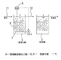
図1は本発明を実施するのに好適な装置の一例を示す構成図である。図1に示す本発明を実施する装置はBOD分解槽1と、亜硝化槽2と、嫌気性アンモニア酸化反応槽3と、BOD分解槽用DO計4と、BOD分解槽用曝気装置5と、亜硝化槽用DO計6と、亜硝化槽用曝気装置7と、から構成される。
FIG. 1 is a block diagram showing an example of an apparatus suitable for carrying out the present invention. An apparatus for carrying out the present invention shown in FIG. 1 includes a
BOD分解槽1に導入する有機性原水とは、例えば、下水処理場で発生する汚泥返流水等であって、比較的高濃度のリン酸イオン(Pとして30〜150mg/L)とアンモニウムイオン(Nとして500〜1500mg/L)を含み、更にマグネシウムイオン(5〜15mg/L)が共存する有機性原水である。
The organic raw water introduced into the
本発明は、亜硝酸型硝化工程と脱窒工程とからなる有機性排水の脱窒方法において、亜硝化槽2の前段に、生物担体が投入され、かつDOが2.8mg/L以下であるように曝気量を制御されたBOD分解槽1を設け、アンモニア性窒素を含む有機性廃水をBOD分解槽1に導入して有機物を分解するBOD分解工程を設けたことを特徴とする有機性排水の脱窒方法であり、本実施形態では、特に、アンモニア性窒素の一部をアンモニア酸化細菌の作用により亜硝酸性窒素に酸化する部分亜硝化工程と、亜硝酸性窒素を電子受容体とし残存したアンモニア性窒素を電子供与体として独立栄養微生物の作用により窒素ガスを発生させる嫌気性アンモニア酸化反応工程とからなる有機性排水の脱窒方法において、亜硝酸槽4の前段に前処理工程を設けた実施形態について説明する。
The present invention relates to a method for denitrification of organic wastewater comprising a nitrite type nitrification step and a denitrification step, wherein a biological carrier is introduced into the preceding stage of the
亜硝酸性窒素を電子受容体とし残存したアンモニア性窒素を電子供与体として独立栄養微生物の作用により窒素ガスを発生させる嫌気性アンモニア酸化反応工程とは、アナモックス菌と呼ばれる独立栄養性脱窒微生物を利用する嫌気性アンモニア酸化反応工程である。 An anaerobic ammonia oxidation reaction process that generates nitrogen gas by the action of autotrophic microorganisms using nitrite nitrogen as an electron acceptor and remaining ammonia nitrogen as an electron donor is an autotrophic denitrifying microorganism called anammox bacteria. This is an anaerobic ammonia oxidation reaction process to be used.
嫌気性アンモニア酸化反応工程を行う嫌気性アンモニア酸化槽3には、図示しないアナモックス菌の汚泥が保持されている。
In the anaerobic
アナモックス菌による嫌気性アンモニア酸化反応を利用した嫌気性アンモニア酸化反応工程では、前記(化1)反応によってアンモニア性窒素と亜硝酸性窒素が窒素ガス(N2)に分解されると考えられている。 In the anaerobic ammonia oxidation reaction process using anaerobic ammonia oxidation reaction by anammox bacteria, it is considered that ammonia nitrogen and nitrite nitrogen are decomposed into nitrogen gas (N 2 ) by the above (chemical formula 1) reaction. .
すなわち、上記嫌気性アンモニア酸化反応工程で効率よく脱窒を行うためには、嫌気性アンモニア酸化反応工程に導入する亜硝化槽流出水12のアンモニア性窒素と亜硝酸性窒素の含有比率がNO2 −/ NH4 +=0.57/0.43=1.32である事が望ましく、前工程である部分亜硝化工程を経た亜硝化槽流出水12が当該含有比率とするように、亜硝化槽2での曝気量を制御する。
That is, in order to efficiently perform denitrification in the anaerobic ammonia oxidation reaction step, the content ratio of ammonia nitrogen and nitrite nitrogen in the
部分亜硝化工程を行う亜硝化槽2の槽内にはアンモニア酸化細菌を担持させた担体9が分散させてあり、曝気量の制御は、底部に設けた曝気装置7からの空気供給量を制御することにより行う。
A
亜硝化槽2の槽内で曝気を行うと、アンモニア酸化細菌による亜硝化反応が促進するが、前記のように高BODの有機性原水中に亜硝酸性窒素イオン(NO2 −)が存在する場合には、亜硝酸性窒素(NO2 −)が脱窒反応を受け、その副生成物として一酸化二窒素(N2O↑)が生じてしまう問題がある。
When aeration is performed in the
本発明では、亜硝化槽流入水11のBODを低減させる前処理を行うことにより、亜硝化工程で生じる前記問題の解決を図っている。また、前処理工程に導入される原水は高BODであるため、前処理工程において亜硝酸性窒素イオンが生じないようにする制御も合せて行い、前処理工程においても脱窒や一酸化二窒素発生の問題が生じないようにしている。
In the present invention, the pretreatment for reducing the BOD of the nitrification
本発明の前処理工程とは、生物担体8が投入され、かつ溶存酸素量が2.8mg/L以下であるように曝気量を制御されたBOD分解槽1に有機性原水10を導入して有機物を分解するBOD分解工程である。
In the pretreatment process of the present invention, the organic raw water 10 is introduced into the
BOD分解工程を行うBOD分解槽1の槽内にはBOD分解菌を担持させた担体8が分散させてあり、曝気量の制御は、底部に設けたBOD分解槽用曝気装置5からの空気供給量を制御することにより行う。また、DOが2.8mg/L以下であるように曝気量の制御を行うために、BOD分解槽用DO計4を備えている。
A
DOを2.8mg/L以下することにより、アンモニア酸化細菌の代謝を抑えつつ、BOD分解菌の代謝のみを選択的に行わせることが可能となる。これにより、BOD分解槽1の槽内では、BOD分解菌の代謝に伴うBOD分解反応のみが選択的に進行し、BOD分解槽1の槽内で、窒素ガスや一酸化二窒素ガスを発生させることなく、BODを低減させることが可能となる。
By controlling DO to 2.8 mg / L or less, it is possible to selectively perform metabolism of BOD-degrading bacteria while suppressing metabolism of ammonia-oxidizing bacteria. As a result, only the BOD decomposition reaction accompanying the metabolism of the BOD-degrading bacteria selectively proceeds in the tank of the
このようにして得られた低BODの亜硝化槽流入水11を亜硝化槽2に導入し、亜硝化槽2の槽内に分散されている担体に担持されたアンモニア酸化細菌を利用した下記の部分亜硝化反応に適した好気性状態を維持できるように、硝化槽用曝気装置7からの酸素供給量を調整する。
The low BOD nitrification
![]()
![]()
ここで本発明によると、亜硝化槽1内に導入される亜硝化槽流入水11は、前記の前処理工程により低BODとなっているため、本工程で従来生じていた窒素ガスや一酸化二窒素ガス等を発生する問題が解消可能となる。
Here, according to the present invention, the
なお、亜硝酸性窒素:アンモニア性窒素=0.57モル:0.43モルとする含有比は、後段のアナモックス工程における嫌気性アンモニア酸化細菌による脱窒反応(化1)に好適な含有比であり、本発明によれば、亜硝化槽11で窒素源が窒素ガスや一酸化二窒素ガスとして失われていた問題が解消する結果、嫌気性アンモニア酸化反応工程に導入する亜硝化槽流出水12のアンモニア性窒素と亜硝酸性窒素の含有比率をNO2 −/ NH4 +=0.57/0.43=1.32とする制御が容易となる効果も得られる。
The content ratio of nitrite nitrogen: ammonia nitrogen = 0.57 mol: 0.43 mol is a content ratio suitable for the denitrification reaction (chemical formula 1) by anaerobic ammonia oxidizing bacteria in the latter anammox process. According to the present invention, as a result of solving the problem that the nitrogen source is lost as nitrogen gas or dinitrogen monoxide gas in the
以下に実施例及比較例をあげて本発明をより具体的に説明する。
(実施例)
図1に示す本発明を実施するのに好適な装置を使用して、BOD分解工程と亜硝化工程と脱窒工程とからなる脱窒方法を実施し、BOD分解槽と亜硝化槽における水質状況及び脱窒量及び一酸化二窒素発生量を測定した結果を以下に示す。なお、本実施例において、BOD分解槽の滞留時間は6時間とし、BOD分解槽の担体には円柱状ポリウレタン担体を使用し、担体投入率は10%とし、DO制御値は1.5mg/Lとし、亜硝化槽の滞留時間は6時間としDO制御値は3.5mg/Lとした。その他の条件は脱窒工程がアナモックス工程の場合に従来一般に採用されている条件と同様とした。
Hereinafter, the present invention will be described more specifically with reference to examples and comparative examples.
(Example)
The apparatus suitable for carrying out the present invention shown in FIG. 1 is used to carry out a denitrification method comprising a BOD decomposition process, a nitrification process and a denitrification process, and the water quality status in the BOD decomposition tank and the nitrification tank The results of measuring the amount of denitrification and the amount of nitrous oxide generated are shown below. In this example, the residence time of the BOD decomposition tank is 6 hours, a cylindrical polyurethane carrier is used as the carrier of the BOD decomposition tank, the carrier charging rate is 10%, and the DO control value is 1.5 mg / L. The residence time in the nitrification tank was 6 hours, and the DO control value was 3.5 mg / L. The other conditions were the same as those conventionally used when the denitrification process was an anammox process.
(比較例1)
図1に示す本発明を実施するのに好適な装置を使用して、BOD分解工程と亜硝化工程と脱窒工程とからなる脱窒方法を実施し、BOD分解槽と亜硝化槽における水質状況及び脱窒量及び一酸化二窒素発生量を測定した結果を以下に示す。なお、本実施例において、BOD分解槽の滞留時間は6時間とし、BOD分解槽の担体には円柱状ポリウレタン担体を使用し、担体投入率は10%とし、DO制御値は3.5mg/Lとし、亜硝化槽の滞留時間は6時間としDO制御値は3.5mg/Lとした。その他の条件は脱窒工程がアナモックス工程の場合に従来一般に採用されている条件と同様とした。
(Comparative Example 1)
The apparatus suitable for carrying out the present invention shown in FIG. 1 is used to carry out a denitrification method comprising a BOD decomposition process, a nitrification process and a denitrification process, and the water quality status in the BOD decomposition tank and the nitrification tank The results of measuring the amount of denitrification and the amount of nitrous oxide generated are shown below. In this example, the residence time of the BOD decomposition tank is 6 hours, a cylindrical polyurethane carrier is used as the carrier of the BOD decomposition tank, the carrier charging rate is 10%, and the DO control value is 3.5 mg / L. The residence time in the nitrification tank was 6 hours, and the DO control value was 3.5 mg / L. The other conditions were the same as those conventionally used when the denitrification process was an anammox process.
(比較例2)
前記実施例と同様の原水について図2に示す装置を使用して、硝化工程前にBOD分解工程を有さない方法により、亜硝化工程と脱窒工程とからなる脱窒方法を実施し、亜硝化槽における水質状況及び脱窒量及び一酸化二窒素発生量を測定した結果を以下に示す。なお、本比較例において、亜硝化槽の滞留時間は12時間としDO制御値は3.5mg/Lとした。その他の条件は脱窒工程がアナモックス工程の場合に従来一般に採用されている条件と同様とした。
(Comparative Example 2)
Using the apparatus shown in FIG. 2 for the raw water similar to the above example, a denitrification method comprising a nitrification step and a denitrification step is performed by a method that does not have a BOD decomposition step before the nitrification step. The results of measuring the water quality in the nitrification tank, the amount of denitrification, and the amount of nitrous oxide generated are shown below. In this comparative example, the residence time in the nitrification tank was 12 hours, and the DO control value was 3.5 mg / L. The other conditions were the same as those conventionally used when the denitrification process was an anammox process.
表1〜表3に示す実施例と比較例1及び2の脱窒量および一酸化二窒素発生量をまとめると下記の表4のようになる。表4において、「(BOD分解槽+亜硝化槽)の脱窒量」とは、有機性原水がBOD分解槽に流入して亜硝化槽から流出される間に脱窒される量を両槽の処理容積量の合計値で割った値を示すものである。また、表4において、「(BOD分解槽+亜硝化槽)の(N2O発生量/NH4 +−N負荷量)」とは、両槽で発生するN2O発生量の合計値を原水中のNH4 +−N量で割った値を示すものである。 Table 4 below summarizes the denitrification amounts and dinitrogen monoxide generation amounts of Examples and Comparative Examples 1 and 2 shown in Tables 1 to 3. In Table 4, “Denitrification amount of (BOD decomposition tank + nitrification tank)” means the amount of denitrification while organic raw water flows into the BOD decomposition tank and flows out of the nitrification tank in both tanks It shows the value divided by the total value of the processing volume. In Table 4, “(N 2 O generation amount / NH 4 + −N load amount) of (BOD decomposition tank + nitrification tank)” is the total value of N 2 O generation amount generated in both tanks. The value divided by the amount of NH 4 + -N in the raw water is shown.
表4に示すように、本発明に係る実施例によれば、BOD分解槽を設けない比較例2と比べて、亜硝化工程での脱窒量も、亜硝化工程での一酸化二窒素発生量も、顕著に抑制された。なお、DO制御値を3.5mg/Lとした比較例1では、本発明の前記効果は得られなかった。 As shown in Table 4, according to the embodiment according to the present invention, the amount of denitrification in the nitrification process is also generated in the nitrification process compared to Comparative Example 2 in which no BOD decomposition tank is provided. The amount was also significantly suppressed. In addition, in the comparative example 1 which made DO control value 3.5 mg / L, the said effect of this invention was not acquired.
1 BOD分解槽
2 亜硝化槽
3 嫌気性アンモニア酸化反応槽
4 BOD分解槽用DO計
5 BOD分解槽用曝気装置
6 亜硝化槽用DO計
7 亜硝化槽用曝気装置
8 生物担体
9 生物担体
10 有機性原水
11 亜硝化槽流入水
12 亜硝化槽流出水
1
Claims (4)
前記亜硝化槽からの流出水を、脱窒槽に導入し、脱窒菌の作用により窒素ガスを発生させる脱窒工程とからなる有機性原水の脱窒方法において、
亜硝酸型硝化工程の前段に、アンモニア性窒素を含む有機性廃水を、生物担体が投入され、かつ溶存酸素量が2.8mg/L以下であるように曝気量を制御されたBOD分解槽に導入して有機物を分解するBOD分解工程を設けることを特徴とする有機性原水の脱窒方法。 A nitrite type nitrification process in which organic raw water containing ammonia nitrogen is introduced into a nitrification tank and oxidized to nitrite nitrogen by the action of ammonia oxidizing bacteria,
In the denitrification method of the organic raw water comprising the denitrification step of introducing the effluent water from the nitrification tank into the denitrification tank and generating nitrogen gas by the action of denitrifying bacteria,
Before the nitrite-type nitrification process, organic wastewater containing ammonia nitrogen is put into a BOD decomposition tank in which the biological carrier is introduced and the aeration amount is controlled so that the dissolved oxygen amount is 2.8 mg / L or less. A method for denitrifying organic raw water, comprising a BOD decomposition step for introducing and decomposing organic matter.
前記脱窒工程が前記亜硝酸型硝化工程で生じた亜硝酸性窒素を電子受容体とし、残存したアンモニア性窒素を電子供与体として独立栄養微生物の作用により窒素ガスを発生させる嫌気性アンモニア酸化反応工程であることを特徴とする請求項1記載の有機性原水の脱窒方法。 The nitrite type nitrification step is a nitrite type nitrification step in which a part of ammonia nitrogen is oxidized to nitrite nitrogen by the action of ammonia oxidizing bacteria,
Anaerobic ammonia oxidation reaction in which the denitrification step generates nitrogen gas by the action of autotrophic microorganisms using nitrite nitrogen generated in the nitrite type nitrification step as an electron acceptor and remaining ammonia nitrogen as an electron donor The method for denitrifying organic raw water according to claim 1, wherein the method is a process.
2. The denitrification step is a normal denitrification step in which nitrogen gas is generated by the action of a denitrifying bacterium using nitrite nitrogen as an electron acceptor and organic matter as an electron donor. Denitrification method for organic wastewater.
Priority Applications (1)
| Application Number | Priority Date | Filing Date | Title |
|---|---|---|---|
| JP2008163393A JP5006845B2 (en) | 2008-06-23 | 2008-06-23 | Method for suppressing generation of nitrous oxide |
Applications Claiming Priority (1)
| Application Number | Priority Date | Filing Date | Title |
|---|---|---|---|
| JP2008163393A JP5006845B2 (en) | 2008-06-23 | 2008-06-23 | Method for suppressing generation of nitrous oxide |
Publications (2)
| Publication Number | Publication Date |
|---|---|
| JP2010000480A true JP2010000480A (en) | 2010-01-07 |
| JP5006845B2 JP5006845B2 (en) | 2012-08-22 |
Family
ID=41582630
Family Applications (1)
| Application Number | Title | Priority Date | Filing Date |
|---|---|---|---|
| JP2008163393A Active JP5006845B2 (en) | 2008-06-23 | 2008-06-23 | Method for suppressing generation of nitrous oxide |
Country Status (1)
| Country | Link |
|---|---|
| JP (1) | JP5006845B2 (en) |
Cited By (8)
| Publication number | Priority date | Publication date | Assignee | Title |
|---|---|---|---|---|
| JP2010094665A (en) * | 2008-09-19 | 2010-04-30 | Metawater Co Ltd | Method for controlling emission of nitrous oxide associated with treatment of nitrogen-containing wastewater |
| JP2011110501A (en) * | 2009-11-27 | 2011-06-09 | Hitachi Ltd | Water treatment equipment |
| JP2011147858A (en) * | 2010-01-20 | 2011-08-04 | Hitachi Ltd | Apparatus and method for treating sewage |
| CN102351366A (en) * | 2011-06-30 | 2012-02-15 | 北京交通大学 | Device and method for treating pharmaceutical waste water through synchronous biological denitrification and devulcanization and autotrophic biological denitrification |
| JP2012035215A (en) * | 2010-08-09 | 2012-02-23 | Hitachi Plant Technologies Ltd | Wastewater treatment apparatus and waste water treatment method |
| JP2015093258A (en) * | 2013-11-13 | 2015-05-18 | 水ing株式会社 | Denitrification method and apparatus |
| JP2015515370A (en) * | 2012-04-04 | 2015-05-28 | ヴェオリア・ウォーター・ソリューションズ・アンド・テクノロジーズ・サポート | Process comprising an ANAMOX microorganism on a biofilm carrier for removing ammonium from a wastewater stream |
| CN108585199A (en) * | 2018-05-03 | 2018-09-28 | 哈尔滨工业大学(威海) | One kind is by introducing AMX(Anammox)Bacterium strengthens the integrated apparatus and method of A/O technique deep denitrifications |
Families Citing this family (1)
| Publication number | Priority date | Publication date | Assignee | Title |
|---|---|---|---|---|
| KR101828212B1 (en) * | 2017-05-29 | 2018-02-12 | 서울과학기술대학교 산학협력단 | Wastewater treatment system using anaerobic ammonium oxidation in mainstream |
Citations (4)
| Publication number | Priority date | Publication date | Assignee | Title |
|---|---|---|---|---|
| JP2001104992A (en) * | 1999-10-12 | 2001-04-17 | Kurita Water Ind Ltd | Method and apparatus for bilogically removing nitrogen |
| JP2005305410A (en) * | 2004-03-25 | 2005-11-04 | Hitachi Plant Eng & Constr Co Ltd | Method and apparatus for removing nitrogen |
| JP2006055739A (en) * | 2004-08-19 | 2006-03-02 | Kurita Water Ind Ltd | Treating method of organic matter- and nitrogen-containing wastewater |
| JP2008126143A (en) * | 2006-11-21 | 2008-06-05 | Hitachi Zosen Corp | Water treatment method |
-
2008
- 2008-06-23 JP JP2008163393A patent/JP5006845B2/en active Active
Patent Citations (4)
| Publication number | Priority date | Publication date | Assignee | Title |
|---|---|---|---|---|
| JP2001104992A (en) * | 1999-10-12 | 2001-04-17 | Kurita Water Ind Ltd | Method and apparatus for bilogically removing nitrogen |
| JP2005305410A (en) * | 2004-03-25 | 2005-11-04 | Hitachi Plant Eng & Constr Co Ltd | Method and apparatus for removing nitrogen |
| JP2006055739A (en) * | 2004-08-19 | 2006-03-02 | Kurita Water Ind Ltd | Treating method of organic matter- and nitrogen-containing wastewater |
| JP2008126143A (en) * | 2006-11-21 | 2008-06-05 | Hitachi Zosen Corp | Water treatment method |
Cited By (9)
| Publication number | Priority date | Publication date | Assignee | Title |
|---|---|---|---|---|
| JP2010094665A (en) * | 2008-09-19 | 2010-04-30 | Metawater Co Ltd | Method for controlling emission of nitrous oxide associated with treatment of nitrogen-containing wastewater |
| JP2011110501A (en) * | 2009-11-27 | 2011-06-09 | Hitachi Ltd | Water treatment equipment |
| JP2011147858A (en) * | 2010-01-20 | 2011-08-04 | Hitachi Ltd | Apparatus and method for treating sewage |
| JP2012035215A (en) * | 2010-08-09 | 2012-02-23 | Hitachi Plant Technologies Ltd | Wastewater treatment apparatus and waste water treatment method |
| CN102351366A (en) * | 2011-06-30 | 2012-02-15 | 北京交通大学 | Device and method for treating pharmaceutical waste water through synchronous biological denitrification and devulcanization and autotrophic biological denitrification |
| CN102351366B (en) * | 2011-06-30 | 2013-01-23 | 北京交通大学 | Device and method for treating pharmaceutical waste water through synchronous biological denitrification and devulcanization and autotrophic biological denitrification |
| JP2015515370A (en) * | 2012-04-04 | 2015-05-28 | ヴェオリア・ウォーター・ソリューションズ・アンド・テクノロジーズ・サポート | Process comprising an ANAMOX microorganism on a biofilm carrier for removing ammonium from a wastewater stream |
| JP2015093258A (en) * | 2013-11-13 | 2015-05-18 | 水ing株式会社 | Denitrification method and apparatus |
| CN108585199A (en) * | 2018-05-03 | 2018-09-28 | 哈尔滨工业大学(威海) | One kind is by introducing AMX(Anammox)Bacterium strengthens the integrated apparatus and method of A/O technique deep denitrifications |
Also Published As
| Publication number | Publication date |
|---|---|
| JP5006845B2 (en) | 2012-08-22 |
Similar Documents
| Publication | Publication Date | Title |
|---|---|---|
| JP5006845B2 (en) | Method for suppressing generation of nitrous oxide | |
| JP4496735B2 (en) | Biological treatment of BOD and nitrogen-containing wastewater | |
| JP5006849B2 (en) | Denitrification method of organic raw water by controlling nitrite type nitrification | |
| KR101176437B1 (en) | Bio-electrochemical wastewater treating apparatus for a simultaneous removal of ammonia and organics and wastewater treatment method using the apparatus | |
| JP4644107B2 (en) | Method for treating wastewater containing ammonia | |
| JP5100091B2 (en) | Water treatment method | |
| JP2000015288A (en) | Waste water treatment method and apparatus | |
| JP4649911B2 (en) | Treatment of organic matter and nitrogen-containing wastewater | |
| JP5424789B2 (en) | Nitrous oxide emission control method for nitrogen-containing wastewater treatment | |
| JP4882175B2 (en) | Nitrification method | |
| JPWO2004074191A1 (en) | Ammonia nitrogen-containing water treatment method | |
| JP4613474B2 (en) | Method for treating ammonia-containing water | |
| JP4734996B2 (en) | Biological treatment method and apparatus for nitrogen-containing water | |
| JP2015058428A (en) | Waste liquid treatment method and apparatus | |
| JP2006325512A (en) | Waste water-treating system | |
| JP2005246135A (en) | Method for biologically removing nitrogen | |
| JP5858763B2 (en) | Nitrogen-containing organic wastewater treatment system and treatment method | |
| JP4848144B2 (en) | Waste water treatment equipment | |
| JP2000308900A (en) | Treatment of ammonia-containing waste water | |
| JP6491056B2 (en) | Nitrogen removal method and nitrogen removal apparatus | |
| JP4570550B2 (en) | Nitrogen removal method and apparatus for high concentration organic wastewater | |
| JP5812277B2 (en) | Nitrogen removal method | |
| JP4419418B2 (en) | Nitrogen-containing wastewater treatment method | |
| JP2007007620A (en) | Method for treating nitrogen-containing liquid waste | |
| JP2003053382A (en) | Nitrification-denitrification treatment method |
Legal Events
| Date | Code | Title | Description |
|---|---|---|---|
| A621 | Written request for application examination |
Free format text: JAPANESE INTERMEDIATE CODE: A621 Effective date: 20110117 |
|
| A977 | Report on retrieval |
Free format text: JAPANESE INTERMEDIATE CODE: A971007 Effective date: 20111017 |
|
| A131 | Notification of reasons for refusal |
Free format text: JAPANESE INTERMEDIATE CODE: A131 Effective date: 20111021 |
|
| A521 | Request for written amendment filed |
Free format text: JAPANESE INTERMEDIATE CODE: A523 Effective date: 20111220 |
|
| TRDD | Decision of grant or rejection written | ||
| A01 | Written decision to grant a patent or to grant a registration (utility model) |
Free format text: JAPANESE INTERMEDIATE CODE: A01 Effective date: 20120508 |
|
| A01 | Written decision to grant a patent or to grant a registration (utility model) |
Free format text: JAPANESE INTERMEDIATE CODE: A01 |
|
| A61 | First payment of annual fees (during grant procedure) |
Free format text: JAPANESE INTERMEDIATE CODE: A61 Effective date: 20120525 |
|
| FPAY | Renewal fee payment (event date is renewal date of database) |
Free format text: PAYMENT UNTIL: 20150601 Year of fee payment: 3 |
|
| R150 | Certificate of patent or registration of utility model |
Ref document number: 5006845 Country of ref document: JP Free format text: JAPANESE INTERMEDIATE CODE: R150 |
|
| S531 | Written request for registration of change of domicile |
Free format text: JAPANESE INTERMEDIATE CODE: R313531 |
|
| FPAY | Renewal fee payment (event date is renewal date of database) |
Free format text: PAYMENT UNTIL: 20150601 Year of fee payment: 3 |
|
| R350 | Written notification of registration of transfer |
Free format text: JAPANESE INTERMEDIATE CODE: R350 |
|
| R250 | Receipt of annual fees |
Free format text: JAPANESE INTERMEDIATE CODE: R250 |
|
| R250 | Receipt of annual fees |
Free format text: JAPANESE INTERMEDIATE CODE: R250 |
|
| R250 | Receipt of annual fees |
Free format text: JAPANESE INTERMEDIATE CODE: R250 |
|
| R250 | Receipt of annual fees |
Free format text: JAPANESE INTERMEDIATE CODE: R250 |
|
| R250 | Receipt of annual fees |
Free format text: JAPANESE INTERMEDIATE CODE: R250 |
|
| R250 | Receipt of annual fees |
Free format text: JAPANESE INTERMEDIATE CODE: R250 |
|
| R250 | Receipt of annual fees |
Free format text: JAPANESE INTERMEDIATE CODE: R250 |
|
| R250 | Receipt of annual fees |
Free format text: JAPANESE INTERMEDIATE CODE: R250 |
|
| R250 | Receipt of annual fees |
Free format text: JAPANESE INTERMEDIATE CODE: R250 |