JP2012148217A - Biological treatment method of wastewater, and wastewater treatment apparatus - Google Patents
Biological treatment method of wastewater, and wastewater treatment apparatus Download PDFInfo
- Publication number
- JP2012148217A JP2012148217A JP2011006992A JP2011006992A JP2012148217A JP 2012148217 A JP2012148217 A JP 2012148217A JP 2011006992 A JP2011006992 A JP 2011006992A JP 2011006992 A JP2011006992 A JP 2011006992A JP 2012148217 A JP2012148217 A JP 2012148217A
- Authority
- JP
- Japan
- Prior art keywords
- gas
- tank
- water
- nitrification
- nitrification tank
- Prior art date
- Legal status (The legal status is an assumption and is not a legal conclusion. Google has not performed a legal analysis and makes no representation as to the accuracy of the status listed.)
- Granted
Links
Images


Classifications
-
- Y—GENERAL TAGGING OF NEW TECHNOLOGICAL DEVELOPMENTS; GENERAL TAGGING OF CROSS-SECTIONAL TECHNOLOGIES SPANNING OVER SEVERAL SECTIONS OF THE IPC; TECHNICAL SUBJECTS COVERED BY FORMER USPC CROSS-REFERENCE ART COLLECTIONS [XRACs] AND DIGESTS
- Y02—TECHNOLOGIES OR APPLICATIONS FOR MITIGATION OR ADAPTATION AGAINST CLIMATE CHANGE
- Y02C—CAPTURE, STORAGE, SEQUESTRATION OR DISPOSAL OF GREENHOUSE GASES [GHG]
- Y02C20/00—Capture or disposal of greenhouse gases
- Y02C20/10—Capture or disposal of greenhouse gases of nitrous oxide (N2O)
-
- Y—GENERAL TAGGING OF NEW TECHNOLOGICAL DEVELOPMENTS; GENERAL TAGGING OF CROSS-SECTIONAL TECHNOLOGIES SPANNING OVER SEVERAL SECTIONS OF THE IPC; TECHNICAL SUBJECTS COVERED BY FORMER USPC CROSS-REFERENCE ART COLLECTIONS [XRACs] AND DIGESTS
- Y02—TECHNOLOGIES OR APPLICATIONS FOR MITIGATION OR ADAPTATION AGAINST CLIMATE CHANGE
- Y02W—CLIMATE CHANGE MITIGATION TECHNOLOGIES RELATED TO WASTEWATER TREATMENT OR WASTE MANAGEMENT
- Y02W10/00—Technologies for wastewater treatment
- Y02W10/10—Biological treatment of water, waste water, or sewage
Abstract
Description
本発明の実施形態は、生物反応装置により原水を生物学的に処理する廃水の生物学的処理方法及び廃水処理装置に関する。 Embodiments of the present invention relate to a biological treatment method and wastewater treatment apparatus for biologically treating raw water with a biological reaction apparatus.
廃水中の窒素成分を生物学的に処理する廃水の処理方法及び装置では、無酸素状態の脱窒槽で脱窒菌により還元処理した後、好気状態の硝化槽で硝化菌により生物酸化処理を行っている。これらの処理過程では、反応副産物としてN2O(亜酸化窒素)ガスが発生することが知られている。N2Oガスは、二酸化炭素ガスの310倍の温室効果を有しているとされている。地球温暖化問題は国際的な問題となっており、温室効果ガスであるN2Oガスの削減は、二酸化炭素ガスやメタンガスの削減とともに重要である。このような背景から、N2Oの生成を抑制するための検討が行われてきた。 In the wastewater treatment method and device that biologically treats nitrogen components in wastewater, after reducing treatment with denitrifying bacteria in an oxygen-free denitrification tank, biooxidation treatment is performed with nitrifying bacteria in an aerobic nitrification tank ing. In these treatment processes, it is known that N 2 O (nitrous oxide) gas is generated as a reaction byproduct. N 2 O gas is said to have a greenhouse effect 310 times that of carbon dioxide gas. The global warming problem has become an international problem, and the reduction of N 2 O gas, which is a greenhouse gas, is important along with the reduction of carbon dioxide gas and methane gas. From such a background, studies for suppressing the generation of N 2 O have been made.
例えば、脱窒槽の前段に微好気性の生物反応槽を設け、硝化槽で発生するN2O含有ガスを微好気槽に直接導入し、N2Oを還元処理するものがある(例えば、特許文献1参照)。また、硝化槽で発生したN2O含有ガスを酸素除去装置に送気し、含有ガスに混在する酸素をあらかじめ除去した脱酸素ガスを脱窒槽の廃水中に導入し、還元処理するものもある(例えば、特許文献2参照)。さらに、硝化槽で発生したN2O含有ガスを回収槽に送気し、硝化液循環ラインで回収槽内に送水された硝化液中に散気することで、N2Oガスを硝化液中に溶解させ、硝化液に溶解されたN2Oを脱窒槽に送水し、還元処理する方式もある(例えば、特許文献3参照)。 For example, there is a type in which a microaerobic biological reaction tank is provided in front of the denitrification tank, N 2 O-containing gas generated in the nitrification tank is directly introduced into the microaerobic tank, and N 2 O is reduced (for example, Patent Document 1). In addition, there is a type in which N 2 O-containing gas generated in a nitrification tank is sent to an oxygen removing device, and deoxygenated gas from which oxygen contained in the contained gas has been removed in advance is introduced into the wastewater of the denitrification tank for reduction treatment. (For example, refer to Patent Document 2). Further, the N 2 O-containing gas generated in the nitrification tank is sent to the recovery tank, and diffused into the nitrification liquid fed into the recovery tank through the nitrification liquid circulation line, so that the N 2 O gas is contained in the nitrification liquid. There is also a method in which N 2 O dissolved in the nitrification solution is fed to a denitrification tank for reduction treatment (see, for example, Patent Document 3).
しかし、微好気槽を用いる方法では、この微好気槽を新設する必要があり、限られたスペースしかない下水処理場においては新たに微好気槽を設置することは困難となる可能性がある。また、酸素除去装置を用いる場合、最適な酸素除去装置として分子ふるい活性炭やガス分離膜が推奨されている。しかし、これらの装置は高価であるうえ、定期的に活性炭もしくは分離膜を交換する必要があり、手間もかかる。 However, in the method using a microaerobic tank, it is necessary to newly install this microaerobic tank, and it may be difficult to newly install a microaerobic tank in a sewage treatment plant with limited space. There is. Moreover, when using an oxygen removal apparatus, molecular sieve activated carbon and a gas separation membrane are recommended as an optimal oxygen removal apparatus. However, these apparatuses are expensive, and it is necessary to periodically replace the activated carbon or the separation membrane, which is troublesome.
このため、既設設備などをできるだけ利用し、N2Oの大気への放出を効果的に抑止できる方法及びシステムが要望されてきた。 For this reason, there has been a demand for a method and system that can utilize existing equipment as much as possible and effectively suppress the release of N 2 O into the atmosphere.
本発明の実施の形態による廃水の生物学的処理方法では、原水を無酸素状態の脱窒槽にて脱窒菌により還元処理し、この脱窒槽を経た被処理水を好気状態の硝化槽にて好気性微生物により生物酸化処理を行うに際し、前記生物学的処理過程で生じたN2Oを含むガスをガス収集機構で収集し、このガス収集機構により収集されたガスを、生物酸化処理してN2OをNO3に変化させることを特徴とする。 In the biological treatment method of wastewater according to the embodiment of the present invention, raw water is reduced by denitrifying bacteria in an oxygen-free denitrification tank, and the treated water that has passed through this denitrification tank is in an aerobic nitrification tank. When performing a biooxidation treatment by an aerobic microorganism, a gas containing N 2 O generated in the biological treatment process is collected by a gas collection mechanism, and the gas collected by the gas collection mechanism is subjected to a biooxidation treatment. It is characterized by changing N 2 O to NO 3 .
本発明の実施の形態による廃水処理装置は、原水を無酸素状態にて脱窒菌により還元処理する脱窒槽と、この脱窒槽を経た被処理水を、曝気による好気状態にて硝化菌により生物酸化処理を行う硝化槽と、硝化処理された硝化液を処理水と活性汚泥とに固液分離する固液分離装置とを有し、前記脱窒槽及び硝化槽での生物学的処理過程で生じたN2Oを含むガスを収集し、N2Oを生物酸化処理する生物反応送へと送るガス収集機構と、このガス収集機構により収集されたガスを生物酸化処理し、N2OをNO3に変化させる生物酸化処理部とをさらに備えたことを特徴とする。 A wastewater treatment apparatus according to an embodiment of the present invention is a denitrification tank that reduces raw water by denitrifying bacteria in an oxygen-free state, and the treated water that has passed through this denitrifying tank is biologically treated by nitrifying bacteria in an aerobic state by aeration. It has a nitrification tank that performs oxidation treatment, and a solid-liquid separation device that separates the nitrified nitrification solution into treated water and activated sludge, and is generated in the biological treatment process in the denitrification tank and the nitrification tank. N collect gas containing 2 O were, a gas collection system for sending and the N 2 O to the feed biological response to biological oxidation process, the gas collection mechanism gases collected by processing the biological oxidation, N 2 O NO And a bio-oxidation treatment part to be changed to 3 .
以下、本発明の実施の形態について説明する。 Embodiments of the present invention will be described below.
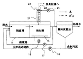
図1は、本発明の廃水処理装置の第1の実施の形態を説明する構成図である。この実施の形態の廃水処理装置は、脱窒槽11、硝化槽12、及び固液分離装置としての最終沈殿池13を備えている。脱窒槽11には、下水などの廃水が原水として導入され、この原水を無酸素状態にて脱窒菌により還元処理する。硝化槽12には、脱窒槽11を経た被処理水が導入され、その底部に設けられた散気管15によりブロワ16から供給される空気を曝気し、好気状態に保つ。そして、この好気状態において、硝化菌により酸化処理を行う。最終沈殿池13には、硝化槽12にて酸化処理された硝化液が導入され、この硝化液を処理水と活性汚泥とに固液分離する。なお、硝化液の一部はポンプ17により脱窒槽11に戻される。また、最終沈殿池13で固液分離された活性汚泥の一部はポンプ18により脱窒槽11に返送され、脱窒槽11内の生物量を維持する。なお、残りの活性汚泥は、余剰汚泥として排出管を介して装置外に排出される。
FIG. 1 is a configuration diagram illustrating a first embodiment of a wastewater treatment apparatus according to the present invention. The wastewater treatment apparatus of this embodiment includes a
上記脱窒槽11及び硝化槽12に対しては、ガス収集機構21及び生物酸化処理部22が設けられている。ガス収集機構21は、脱窒槽11及び硝化槽12から、詳細を後述するN2Oを含むガスを収集する。生物酸化処理部22は、このガス収集機構21により収集されたガスを生物酸化処理し、N2OをNO3に変化させる。
For the
この実施の形態では、生物酸化処理部22として、ガス収集機構21により収集されたガスに散水してガス成分を水中に溶解させる散水装置23を有するものを用いている。そして、このガス成分を溶解した水を硝化槽12に戻すことにより酸化処理し、N2OをNO3に変化させる。
In this embodiment, as the biological
上記構成において、原水は無酸素状態の脱窒槽11に流入し、有機物が分解された後、好気状態の硝化槽12に送られる。この硝化槽12で処理された硝化液の一部は循環路を介して脱窒槽11に戻され、残りが最終沈殿池13に送られる。硝化槽12では、散気管15によりブロワ16から供給されたエアが散気され、好気性条件下で活性汚泥中の好気性微生物である硝化菌により廃水中のアンモニア性窒素が亜硝酸性窒素や硝酸性窒素に酸化処理される。また、脱窒槽11で処理しきれなかった廃水中の有機物が水と二酸化炭素に分解される。
In the above configuration, the raw water flows into the oxygen-
この硝化槽12からは、ポンプ17を有する循環路により前段の脱窒槽11に液が循環されるので、脱窒槽11では、亜硝酸性窒素及び硝酸性窒素が、脱窒菌により還元処理されて窒素ガスに還元する。
Since the liquid is circulated from the
このような廃水処理の過程において、硝化槽12での酸化処理の反応副産物として、また脱窒槽11での還元処理の中間生成物として前述したN2O(亜酸化窒素)が生成される。この中間生成物であるN2Oガスは、常時生成されているわけではなく、脱窒槽11では不完全脱窒(原因として、溶存酸素の混入、硝酸負荷が高すぎる、脱窒菌が利用する有機物不足、等で生じる。)が生じているときに発生する。また、硝化槽11では不完全硝化(アンモニア・有機物負荷が高いことによる酸素不足)が生じているときに発生する。他の要因でN2Oが生成される可能性はあるが、多くは上記2つが大きな要因であると考えられる。
In the process of such wastewater treatment, the aforementioned N 2 O (nitrous oxide) is produced as a reaction byproduct of the oxidation treatment in the
生成されたN2Oガスは硝化槽12および脱窒槽11のヘッドスペース部に空気、あるいは他の生成ガスと共に溜まる。このN2Oガスが大気にそのまま放出されると前述のように地球温暖化対策上問題が生じる。そこで、その抑止を図るため、ガス収集機構21により収集する。ガス収集機構21により脱窒槽11及び硝化槽12から収集されたN2O含有ガスは、生物酸化処理部22へ送気される。
The generated N 2 O gas accumulates in the head space portion of the
生物酸化処理部22は、N2O含有ガスの流通経路に散水装置23を設置したものであり、この散水装置23には硝化槽12から排出される硝化液がポンプ24により供給され、散水されている。このため、収集されたN2O含有ガスのガス成分は散水されている硝化液中に溶解され、硝化槽12に返送される。そして、この硝化槽12で生物酸化処理されNO3となる。
The biological
このように、脱窒槽11及び硝化槽12内で発生したN2O含有ガスは、生物酸化処理部22を構成する散水装置23により散水された硝化液中に溶解された後、硝化槽12で再度硝化菌により酸化処理されることにより大幅に低減される。すなわち、ガス中のN2Oを硝化・脱窒の処理系内で処理することができる。これにより、廃水処理装置から発生するN2Oガスを無害化するための特別な装置を必要とすることなく、既存設備にガス収集機構21、生物酸化処理部22、および散水装置23を追加するだけの簡単な構成により、N2Oガスが大気に放出されるのを効果的に低減することができる。
As described above, the N 2 O-containing gas generated in the
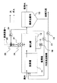
なお、生物酸化処理部22の散水装置23から散水された水と、ガス収集機構21によって収集されたガスとの接触部分に、これらの気液接触面積を増大させるため、例えば、図2で示すような邪魔板25を設けてもよい。このように構成すれば、気液の接触面積が増大することにより、N2O含有ガスの硝化液への溶解効率を上げることができる。また、ガス収集機構21は、ガスをファンにより収集してもよい。さらに、散水する液体は硝化液に限らず、硝化液から固液分離された処理水、或いは通常の水道水でもよい。
In addition, in order to increase these gas-liquid contact areas in the contact part of the water sprinkled from the
図3は上記第1の実施の形態の変形例であり、生物酸化処理部22は、散水装置23からの散水によりガス成分を溶解した水を硝化槽12に戻す経路中に、好気性微生物を付着させる担体26を配置している。すなわち、図示のように、散水装置23の下部に、好気性微生物を付着させるための担体26を配したものである。担体26の材質は何でもよく、例えば、表面を粗面に加工したプラスチック製小片の集合体ように、好気性微生物が効果的に付着される、通気性を有するものを用いるとよい。
FIG. 3 shows a modification of the first embodiment, in which the biological
このように構成すると、N2O含有ガスを溶解した硝化液が担体26に接触することで、担体に付着した好気性微生物によりN2Oを処理することができ、N2Oの分解除去率を向上させることができる。なお、散水した水が担体26に接触する構成であれば、図示の構成によらずどのようであってもよい。
With this configuration, by nitrification prepared by dissolving the N 2 O-containing gas is brought into contact with the
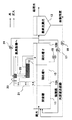
図4及び図5は本発明の第2の実施の形態を示すものである。この実施の形態では、硝化槽12を、処理方向に対して複数に区分している。図の例では、処理方向に対して前後2つに区分したので前段部12A及び後段部12Bとする。これら前段部12A及び後段部12Bは、被処理水が流通可能に構成されている。また、散気管15は前段部12A及び後段部12Bに対して共通に設けている。
4 and 5 show a second embodiment of the present invention. In this embodiment, the
図4では、ガス収集機構21は硝化槽12の前段部12Aからガスを収集する。生物酸化処理部22は、収集されたガスに対して散水装置23により散水し、ガス成分を溶解させた後、このガス成分を溶解した水を硝化槽12の後段部12Bに戻すように構成している。また、図5では、ガス収集機構21は硝化槽12の後段部12Bからガスを収集する。生物酸化処理部22は、収集されたガスに対して散水装置23により散水し、ガス成分を溶解させた後、このガス成分を溶解した水を硝化槽12の前段部12Aに戻すように構成している。
In FIG. 4, the
ここで、図4のように硝化槽12の前段部12Aでガスを収集し、後段部12Bにガスを溶解した水を戻すのは、前段部12Aの方が後段部12BよりN2O含有ガスの発生量が多い場合である。すなわち、脱窒槽11で不完全反応が起こっている場合、前述のようにN2Oが生成される。このN2Oの一部は被処理水中に溶解され、硝化槽12の前段部12Aに流入する。そして、この前段部12Aにおいては、水中に溶解していたN2Oが、散気管15によるバブリングにより気体中に放出され、N2O含有ガスとなる。このため脱窒槽11に近い前段部12AからのN2O含有ガスの発生量が多くなる。このような場合は、図4のような構成とすることで、脱窒反応過程で生じたN2Oを効率良く処理することが可能となり、N2Oの放出量を効果的に抑制できる。
Here, as shown in FIG. 4, the gas is collected in the front stage 12A of the
これに対して、図5のように硝化槽12の後段部12Bでガスを収集し、前段部12Aにガスを溶解した水を戻すのは、後段部12Bの方が前段部12AよりN2O含有ガスの発生量が多い場合である。すなわち、硝化槽12においては有機物の酸化が生じ、後段に進むほど硝化反応が進む。この硝化反応の進行に伴ってN2O含有ガスが発生することが報告されている(例えば、前記特許文献3等)。このため図5では、後段部12Bで生じたN2Oガスを集めて、前段部12Aに戻すことによって、N2Oの酸化を狙ったものである。この方式によれば、硝化過程で生じたN2Oを効率よく酸化処理することが可能となる。
On the other hand, as shown in FIG. 5, the gas is collected in the
上述した図4の構成及び図5の構成のいずれを採用するかは、廃水処理装置としての個々の特性に応じて決めればよい。いずれにおいても、N2Oを液中に溶解させ、硝化槽12に流下させることにより、再溶解させたN2Oを硝酸に酸化させることが可能となる。
Which of the configuration of FIG. 4 and the configuration of FIG. 5 described above is adopted may be determined according to individual characteristics as the wastewater treatment apparatus. In any case, it is possible to oxidize the re-dissolved N 2 O to nitric acid by dissolving N 2 O in the liquid and flowing it down to the
なお、N2Oを液中に溶解させ硝化液を硝化槽12に流下させる管路には、図示のようにU字状部を設けて満水構造とし、流下側からのガスの逆流を防いでいる。
In addition, as shown in the figure, a U-shaped portion is provided in the pipeline for dissolving N 2 O in the liquid and allowing the nitrification liquid to flow down to the
なお、硝化槽12の、図4における後段部12B、及び図5における前段部12Aは、それぞれの図では密閉状態で描かれているが、実際には散気管15から噴出した空気を外部に逃がす逃げ部が形成されているものとする。
The
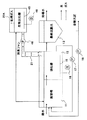
図6は、上述した第2の実施の形態の変形例を示すものである。この例でも硝化槽12は、処理方向に対して複数に区分され、前段部12Aと後段部12Bとを有するものとする。また、これら区分された前段部12Aと後段部12Bとは被処理水が流通可能に構成されている。
FIG. 6 shows a modification of the above-described second embodiment. Also in this example, the
これら前段部12A及び後段部12Bに対しては、それぞれガス収集機構21A,21Bを設けている。これらガス収集機構21A,21Bは、それぞれ対応する開閉弁31A,31Bを介して硝化槽12の区分された前段部12A及び後段部12Bにそれぞれ連結して、いずれかからもガスを収集可能に構成している。
生物酸化処理部22は、ガス収集機構21A,21Bのいずれかにより収集されたガスに散水する散水装置23を有する。この散水装置23の下流側は、満水部を経たのち、それぞれ対応する開閉弁32A,32Bを介して硝化槽12の後段部12B及び前段部12Bにそれぞれ連結している。つまり、これらのいずれにもガス成分を溶解した水を戻せるように構成している。また、この生物酸化処理部22の散水装置23を経た反対側は、それぞれ対応する排気弁33A,33Bを介して外部の脱臭設備などに通じている。
The biological
さらに、硝化槽12の前段部12A及び後段部12Bから生じるガスに含まれるN2O濃度を測定する測定装置35を設ける。この測定装置35は、前段部12Aからのガスに含まれるN2O濃度が後段部12Bからのガスより高い場合は、図示しないコントローラにより、前段部12Aに通じるガス収集機構21Aの開閉弁31Aを開いて、前段部12Aからのガスを収集させる。また、生物酸化処理部22の、後段部12Bに通じる開閉弁32Aを開放して、この後段部12Bにガス成分を溶解した水を戻す。さらに対応する排気弁33Aを開き、散水装置23をとおり、ガス成分が溶出されたガスを脱臭装置などへ排気させる。
Furthermore, a measuring
これに対して、後段部12Bからのガスに含まれるN2O濃度が前段部12Aからのガスより高い場合、測定装置35は、図示しないコントローラにより、後段部12Bに通じるガス収集機構21Bの開閉弁31Bを開放して、後段部12Bからのガスを収集させる。また、生物酸化処理部22の、前段部12Aに通じる開閉弁32Bを開放して、この前段部12Aにガス成分を溶解した水を戻す。さらに対応する排気弁33Bを開き、散水装置23をとおり、ガス成分が溶出されたガスを脱臭装置などへ排気させる。
On the other hand, when the N 2 O concentration contained in the gas from the
すなわち、前段の硝化槽12Aおよび後段の硝化槽12Bからの収集ガス中のN2O濃度を測定し、測定値が高い方の硝化槽12A又は12Bより発生ガスを収集して液中に溶解させ、測定値が低い方の硝化槽12B又は12Aへ流下させるようにした。これにより、脱窒反応過程および硝化反応過程で発生するN2Oを効率良く処理することができる。
That is, the N 2 O concentration in the collected gas from the preceding nitrification tank 12A and the
なお、前段の硝化槽12Aおよび後段の硝化槽12Bからの収集ガス中のN2O濃度を測定し、ガスの収集先と、散水した水の返送先を硝化槽の前段12Aと後段12Bのいずれかに決定する構成であれば図示構成に限らず、どのようなものであってもよい。
The N 2 O concentration in the collected gas from the nitrification tank 12A at the front stage and the
上記実施の形態では、硝化槽12の区分数を2つとした場合を例示したが、もちろん3つ以上に区分してもよい。この場合、前段部とは、脱窒槽11に近い側の区分であればどこでもよく、必ずしも脱窒槽11に隣接した区分を指すものではない。同様に、後段部とは、前段部に対する後段部であればどこでもよく、必ずしも硝化槽12の排出部分を指すものではない。
In the said embodiment, although the case where the division | segmentation number of the
また、この第2の実施形態では図示しなかったが、第1の実施の形態で変形例として説明した気液面積増大用の邪魔板25や、好気性微生物の担体26を、設置してもよいことは勿論である。
Although not shown in the second embodiment, the
図7は、前述した図1の実施形態の変形例であり、ガス収集機構21が収集するガスのN2O濃度を測定する測定装置37を設けている。この測定装置37で測定されたN2O濃度はコントローラ(制御部)38に入力され、予め設定した値(N2O濃度目標値)と比較される。コントローラ38は、N2O濃度測定値が、予め設定した値以上の場合、散水装置23による散水を実行させるべくポンプ24を起動制御する。すなわち、収集ガス中のN2O濃度を測定し、測定値が設定した目標値よりも高いときのみ、散水用のポンプ24を作動させて、N2Oガスを再溶解させるものである。これにより、散水用のポンプ24のランニングコストを低減することができる。
FIG. 7 is a modification of the embodiment of FIG. 1 described above, and is provided with a measuring
また、コントローラ38は、N2Oの測定値と目標値の偏差に応じて散水量を演算し、散水用のポンプ24を制御して、散水量を調整するものでもよい。さらに、測定されたN2O濃度に応じて、ブロワ16を制御し、硝化槽12に対する曝気量を調整するようにしてもよい。
Further, the
これらは、収集ガス中に含まれるN2Oの測定値に応じた制御を行うものであり、無駄な運転を防止して効率的な運用が可能となる。 These perform control according to the measured value of N 2 O contained in the collected gas, and can prevent wasteful operation and enable efficient operation.
図8は第3の実施の形態を示している。なお、前述した各実施の形態と同じ装置及び部材には同符号を付して説明する。 FIG. 8 shows a third embodiment. In addition, the same code | symbol is attached | subjected and demonstrated to the same apparatus and member as each embodiment mentioned above.
脱窒槽11、硝化槽12、固液分離装置としての最終沈殿池13、硝化槽12から脱窒槽11への循環路については、前述した各実施の形態と同様であり、これらと同じ装置及び部材には同符号を付している。
The
この実施の形態では、生物酸化処理部22として、被処理水を生物学処理する生物反応槽22Aを用いている。この生物反応槽22Aの被処理水に対しては、槽内底部に設けられた散気管45により、ブロワ46から送風される空気が曝気される。
In this embodiment, a
脱窒槽11及び硝化槽12から生じたガスは、ガス収集機構21により収集され、ファン48により生物反応槽22A内の被処理水中に吹き込まれる。なお、生物反応槽22A内の被処理水には、別途用意した被処理水や、図8で示すように脱窒槽11内の被処理水を、或いは、図9で示すように硝化槽12内の被処理液を、バッチ式で取り入れてもよい。
The gas generated from the
このように、硝化槽12での硝化反応、及び脱窒槽11での脱窒反応の中間物質として生成したN2Oガスならびに臭気ガスを、ガス収集機構21のガス経路を介して生物反応槽22Aに直接導入するようにした。また、生物反応槽22Aでの生物反応による処理水は、バッチ式で脱窒槽11又は硝化槽12へ戻すように構成した。
As described above, the N 2 O gas and the odor gas generated as intermediate substances of the nitrification reaction in the
上記構成によると、生物反応槽22AではN2Oを酸化すると共に、発生した硫化水素ガスやアンモニアガス等の臭気ガスも酸化脱臭できる。これにより、N2Oの処理と臭気ガスの脱臭処理を同時に行うことができる。生物反応槽22Aの有機物負荷や窒素負荷は硝化槽12に比べて低いことから不完全酸化が起こりにくく、より完全なN2Oの酸化処理が期待できる。なお、処理水の返送場所は図10のように原水槽(図示せず)であってもよい。
According to the above configuration, the
図11は上述した第3の実施の形態の変形例であり、生物酸化処理部22としての生物反応槽22Bは、槽内の高さ方向中間部に、好気生微生物を付着させた担体51を配置し、その上部に散水装置52を設けたものである。この散水装置52は、最終沈殿池13にて硝化液から分離された処理水を散水する。脱窒槽11及び硝化槽12から生じたガスは、ガス収集機構21により収集され、ファン48により担体51の下方空間に供給し、この担体51の配置部分を上向流で通過する。
FIG. 11 shows a modification of the above-described third embodiment. A
ここで、担体51は、前述のように硝化菌をはじめとする好気性微生物を付着させたものであり、収集したN2O含有ガスを反応槽22Bの内部に上向流で通気させることにより、担体51に付着させた好気性微生物によりN2Oを効率良く酸化処理することができる。この場合、ガス収集機構21により収集されたガスは、担体51の下方空間に吹き込まれるので、液中に吹き込む場合に比べ、ファン48の容量を小さくでき、運転コストの低減が期待できる。
Here, as described above, the
なお、生物反応槽22Bで発生した処理水は脱窒槽11返送するように構成した。この他、処理水の返送場所は硝化槽や原水槽でも良い。
The treated water generated in the
上述の各実施の形態では、硝化槽12で硝化菌により酸化処理された硝化液を、最終沈殿池13により処理水と活性汚泥とに固液分離していたが、最終沈殿池13を用いないで固液分離する膜分離活性汚泥法を用いてもよい。
In each of the above-described embodiments, the nitrification solution oxidized by nitrifying bacteria in the
この膜分離活性汚泥法では、硝化槽12内の下流部分に膜ろ過装置を設け、この膜ろ過装置により硝化槽12内で固液分離を行い、分離された処理液を取り出すものである。この場合、硝化槽12からは前述した各実施の形態と同様に硝化液の一部が脱窒槽11に返送される。また、硝化槽12内には、膜ろ過装置により固液分離された活性汚泥が蓄積されるので、硝化槽12内から、この蓄積された活性汚泥を引き抜く。引き抜かれた活性汚泥は、前述した各実施の形態と同様に、その一部は脱窒槽11に返送され、残りは余剰汚泥として装置外に排出される。
In this membrane separation activated sludge method, a membrane filtration device is provided in the downstream portion in the
このように、本発明の各実施の形態では、原水を無酸素状態の脱窒槽にて脱窒菌により還元処理し、この脱窒槽を経た被処理水を曝気され好気状態の硝化槽にて硝化菌により酸化処理を行うに際し、生物学的処理過程で生じたN2Oを含むガスをガス収集機構で収集し、このガス収集機構により収集されたガスを、酸化処理してN2OをNO3に変化させるので、既存設備の利用によりN2Oの大気への放出を効果的に抑制することができる。 As described above, in each embodiment of the present invention, raw water is reduced by denitrifying bacteria in an oxygen-free denitrification tank, and the treated water that has passed through the denitrification tank is aerated and nitrified in an aerobic nitrification tank. In performing oxidation treatment with bacteria, a gas containing N 2 O generated in the biological treatment process is collected by a gas collecting mechanism, and the gas collected by this gas collecting mechanism is oxidized to convert N 2 O into NO. since changing the 3, it is possible to effectively suppress the release into the atmosphere of N 2 O by use of existing facilities.
本発明のいくつかの実施形態を説明したが、これらの実施形態は例として提示したものであり、発明の範囲を限定することは意図していない。これら新規な実施形態は、その他のさまざまな形態で実施されることが可能であり、発明の要旨を逸脱しない範囲で、種々の省略、置き換え、変更を行うことができる。これらの実施形態やその変形は、発明の範囲や要旨に含まれると共に、特許請求の範囲に記載された発明とその均等の範囲に含まれる。 Although several embodiments of the present invention have been described, these embodiments have been presented by way of example and are not intended to limit the scope of the invention. These novel embodiments can be implemented in various other forms, and various omissions, replacements, and changes can be made without departing from the scope of the invention. These embodiments and modifications thereof are included in the scope and gist of the invention, and are included in the invention described in the claims and the equivalents thereof.
11・・・脱窒槽
12・・・硝化槽
21・・・ガス収集機構
22・・・生物酸化処理部
22A,22B・・・生物反応槽
23…散水装置
25…邪魔板
26…担体
DESCRIPTION OF
Claims (18)
前記生物学的処理過程で生じたN2Oを含むガスをガス収集機構で収集し、このガス収集機構により収集されたガスを、液中に溶解させ酸化処理し、N2OをNO3に変化させる
ことを特徴とする廃水の生物学的処理方法。 This is a biological treatment method for wastewater in which raw water is reduced by denitrifying bacteria in an anaerobic denitrification tank, and the treated water passed through this denitrification tank is oxidized by nitrifying bacteria in an aerobic nitrification tank. And
A gas containing N 2 O generated in the biological treatment process is collected by a gas collecting mechanism, and the gas collected by the gas collecting mechanism is dissolved in a liquid and oxidized to convert N 2 O into NO 3 . Biological treatment method of wastewater characterized by changing.
前記脱窒槽及び硝化槽での生物学的処理過程で生じたN2Oを含むガスを収集するガス収集機構と、
このガス収集機構により収集されたガスを液中に溶解させ酸化処理し、N2OをNO3に変化させる生物酸化処理部と、
を備えたことを特徴とする廃水処理装置。 A denitrification tank that performs reduction treatment of raw water with denitrifying bacteria in the absence of oxygen, a nitrification tank that oxidizes the treated water that has passed through this denitrification tank with nitrifying bacteria in an aerobic state by aeration, and an oxidized nitrification A wastewater treatment device having a solid-liquid separation device for solid-liquid separation of the liquid into treated water and activated sludge,
A gas collection mechanism for collecting a gas containing N 2 O generated in the biological treatment process in the denitrification tank and the nitrification tank;
A bio-oxidation unit that dissolves the gas collected by the gas collection mechanism in a liquid and oxidizes the gas to change N 2 O to NO 3 ;
A wastewater treatment apparatus characterized by comprising:
前記ガス収集機構は硝化槽の前記前段部からガスを収集し、前記生物酸化処理部は、ガス成分を溶解した水を硝化槽の前記後段部に戻し、硝化槽で酸化する
ことを特徴とする請求項3に記載の廃水処理装置。 The nitrification tank is divided into a plurality of treatment directions, and the front and rear stages with respect to the divided treatment directions are configured to allow the water to be treated to flow,
The gas collecting mechanism collects gas from the front part of the nitrification tank, and the biological oxidation treatment part returns the water in which the gas component is dissolved to the rear part of the nitrification tank and oxidizes it in the nitrification tank. The wastewater treatment apparatus according to claim 3.
前記ガス収集機構は硝化槽の前記後段部からガスを収集し、前記生物酸化処理部は、ガス成分を溶解した水を硝化槽の前記前段部に戻し、硝化槽で酸化する
ことを特徴とする請求項3に記載の廃水処理装置。 The nitrification tank is divided into a plurality of treatment directions, and the front and rear stages with respect to the divided treatment directions are configured to allow the water to be treated to flow,
The gas collecting mechanism collects gas from the rear stage part of the nitrification tank, and the biological oxidation treatment part returns the water in which the gas component is dissolved to the front stage part of the nitrification tank, and oxidizes in the nitrification tank. The wastewater treatment apparatus according to claim 3.
前記ガス収集機構はそれぞれ開閉弁を介して前記硝化槽の前記前段部及び後段部にそれぞれ連結し、これらのいずれかからもガスを収集可能であり、前記生物酸化処理部はそれぞれ開閉弁を介して前記硝化槽の前記後段部及び前段部にそれぞれ連結し、これらのいずれにもガス成分を溶解した水を戻すことが可能な構成で、硝化槽で酸化する、
ことを特徴とする請求項3に記載の廃水処理装置。 The nitrification tank is divided into a plurality of treatment directions, and the front and rear stages with respect to the divided treatment directions are configured to allow the water to be treated to flow,
The gas collecting mechanisms are respectively connected to the front and rear stages of the nitrification tank via on-off valves, respectively, and can collect gas from either of them, and the biological oxidation treatment parts are respectively connected to the on-off valves. Connected to the rear stage and the front stage of the nitrification tank, respectively, and the structure that can return the water in which the gas component is dissolved to any of these, is oxidized in the nitrification tank.
The wastewater treatment apparatus according to claim 3.
前記硝化槽の前記前段部からのガスのN2O濃度が前記後段部からのガスより高い場合は、前記前段部に通じる前記ガス収集機構の開閉弁を開いてこの前段部からのガスを収集させ、かつ前記生物酸化処理部は、前記後段部に通じる開閉弁を開いてこの後段部にガス成分を溶解した水を戻させ、
前記硝化槽の前記後段部からのガスのN2O濃度が前記前段部からのガスより高い場合は、前記後段部に通じる前記ガス収集機構の開閉弁を開いてこの後段部からのガスを収集させ、かつ前記生物酸化処理部は、前記前段部に通じる開閉弁を開いてこの前段部にガス成分を溶解した水を戻させる
ことを特徴とする請求項6に記載の廃水処理装置。 The measuring device has a measuring device for measuring the N 2 O concentration of the gas generated from the front part and the rear part of the nitrification tank,
When the N 2 O concentration of the gas from the front stage part of the nitrification tank is higher than the gas from the rear stage part, the gas collecting mechanism opening / closing valve leading to the front stage part is opened to collect the gas from the front stage part And the biological oxidation treatment unit opens an on-off valve leading to the rear stage part to return water in which the gas component is dissolved to the rear stage part,
When the N 2 O concentration of the gas from the rear stage of the nitrification tank is higher than the gas from the front stage, the gas collection mechanism leading to the rear stage is opened to collect the gas from the rear stage The waste water treatment apparatus according to claim 6, wherein the biological oxidation treatment unit opens an on-off valve that communicates with the front stage and returns water in which the gas component is dissolved to the front stage.
Priority Applications (2)
| Application Number | Priority Date | Filing Date | Title |
|---|---|---|---|
| JP2011006992A JP5238830B2 (en) | 2011-01-17 | 2011-01-17 | Waste water treatment equipment |
| CN201210014874.3A CN102583735B (en) | 2011-01-17 | 2012-01-17 | Biological treatment method for wastewater and wastewater treatment device |
Applications Claiming Priority (1)
| Application Number | Priority Date | Filing Date | Title |
|---|---|---|---|
| JP2011006992A JP5238830B2 (en) | 2011-01-17 | 2011-01-17 | Waste water treatment equipment |
Publications (2)
| Publication Number | Publication Date |
|---|---|
| JP2012148217A true JP2012148217A (en) | 2012-08-09 |
| JP5238830B2 JP5238830B2 (en) | 2013-07-17 |
Family
ID=46473095
Family Applications (1)
| Application Number | Title | Priority Date | Filing Date |
|---|---|---|---|
| JP2011006992A Active JP5238830B2 (en) | 2011-01-17 | 2011-01-17 | Waste water treatment equipment |
Country Status (2)
| Country | Link |
|---|---|
| JP (1) | JP5238830B2 (en) |
| CN (1) | CN102583735B (en) |
Cited By (3)
| Publication number | Priority date | Publication date | Assignee | Title |
|---|---|---|---|---|
| JP2012228646A (en) * | 2011-04-26 | 2012-11-22 | Hitachi Ltd | Biological water treating apparatus |
| CN106277570A (en) * | 2016-08-10 | 2017-01-04 | 河南师范大学 | A kind of sewage disposal and N2the coupling device of O reduction of discharging and operation method thereof |
| KR101870673B1 (en) | 2018-02-27 | 2018-06-25 | 대가파우더시스템 주식회사 | Bio filter system |
Families Citing this family (2)
| Publication number | Priority date | Publication date | Assignee | Title |
|---|---|---|---|---|
| CN103922469B (en) * | 2014-04-08 | 2016-01-13 | 北京工业大学 | N in a kind of half short distance nitration/Anammox sewage water denitrification process 2the collection device that O produces and method |
| CN114538710A (en) * | 2022-03-01 | 2022-05-27 | 桂林理工大学 | N2O emission reduction sewage integrated treatment system and method |
Citations (20)
| Publication number | Priority date | Publication date | Assignee | Title |
|---|---|---|---|---|
| JPS58193796A (en) * | 1982-05-07 | 1983-11-11 | Osaka Gas Co Ltd | Biologically denitrifying method of waste water |
| JPH0261424U (en) * | 1988-10-26 | 1990-05-08 | ||
| JPH06190241A (en) * | 1991-03-06 | 1994-07-12 | Ebara Infilco Co Ltd | Method and apparatus for biological treatment of dinitrogen oxide |
| JPH10128389A (en) * | 1996-11-01 | 1998-05-19 | Hitachi Plant Eng & Constr Co Ltd | Method and apparatus for waste water treatment |
| JPH10180292A (en) * | 1996-12-24 | 1998-07-07 | Hitachi Plant Eng & Constr Co Ltd | Method of removing nitrogen from waste water and device therefor |
| JP2000246055A (en) * | 1999-03-04 | 2000-09-12 | Hitachi Plant Eng & Constr Co Ltd | Method and apparatus for biologically treating nitrous oxide gas |
| JP2000279752A (en) * | 1999-03-30 | 2000-10-10 | Mitsubishi Heavy Ind Ltd | Nitrous oxide adsorbent, adsorption tower and waste water treatment |
| JP2002204926A (en) * | 2001-01-12 | 2002-07-23 | Kurabo Ind Ltd | Method for removing nitrous oxide in gas and system for removing it |
| JP2003117337A (en) * | 2001-10-12 | 2003-04-22 | Kurita Water Ind Ltd | Method for manufacturing ripe compost-like substance and manufacturing facility |
| WO2004074191A1 (en) * | 2003-02-21 | 2004-09-02 | Kurita Water Industries Ltd. | Method for treating water containing ammonia nitrogen |
| JP2005177758A (en) * | 2005-02-18 | 2005-07-07 | Ebara Corp | Biological deodorization method of odorant gas containing ammonia and apparatus |
| JP2007075821A (en) * | 2006-12-22 | 2007-03-29 | Hitachi Plant Technologies Ltd | Biological treatment process and device of nitrous oxide gas |
| JP2009165958A (en) * | 2008-01-16 | 2009-07-30 | Panasonic Corp | Treatment state judging method of aeration tank and wastewater treatment control system using it |
| WO2009140970A1 (en) * | 2008-05-20 | 2009-11-26 | Aarhus Universitet | A method and a system for purifying and deodorising discharge gases from organic waste producing facilities |
| JP2010094665A (en) * | 2008-09-19 | 2010-04-30 | Metawater Co Ltd | Method for controlling emission of nitrous oxide associated with treatment of nitrogen-containing wastewater |
| JP2010099560A (en) * | 2008-10-22 | 2010-05-06 | Metawater Co Ltd | Air supply system and air supply method |
| JP2010269255A (en) * | 2009-05-22 | 2010-12-02 | Hitachi Ltd | Sewage treatment method |
| JP2011092831A (en) * | 2009-10-28 | 2011-05-12 | Metawater Co Ltd | System and method for reducing amount of generated gas |
| JP2011104585A (en) * | 2009-10-20 | 2011-06-02 | Metawater Co Ltd | Wastewater treatment method and wastewater treatment apparatus |
| JP2011110501A (en) * | 2009-11-27 | 2011-06-09 | Hitachi Ltd | Water treatment equipment |
Family Cites Families (7)
| Publication number | Priority date | Publication date | Assignee | Title |
|---|---|---|---|---|
| EP0223803A1 (en) * | 1985-05-25 | 1987-06-03 | Hölter, Heinz, Dipl.-Ing. | METHOD FOR SIMULTANEOUSLY REMOVING BY WASHING SO 2?, NO x? AND OPTIONALLY OTHER NOXIOUS SUBSTANCES CONTAINED IN FLUE GASES IN HEATING INSTALLATIONS SUPPLIED WITH FOSSILE FUELS |
| CN2912776Y (en) * | 2006-01-22 | 2007-06-20 | 石建平 | Recovering device with spraying function |
| CN1935708A (en) * | 2006-10-19 | 2007-03-28 | 北京科技大学 | Treatment device with bio-sludge degrading and denitrogenation, and its operating method |
| CN201093505Y (en) * | 2007-06-08 | 2008-07-30 | 东莞丰裕电机有限公司 | Environment protection type medical refuse incinerator |
| CN101139155B (en) * | 2007-08-20 | 2010-08-11 | 北京科技大学 | Non-excess activated sludge discharged printing and dyeing wastewater processing equipment and operation method thereof |
| CN201380044Y (en) * | 2008-12-11 | 2010-01-13 | 浙江菲尔特环保工程有限公司 | Waste gas purification device for spraying coating |
| CN201634652U (en) * | 2009-11-13 | 2010-11-17 | 北京中环瑞德环境工程技术有限公司 | High efficiency biogas biochemical combination desulfurization device |
-
2011
- 2011-01-17 JP JP2011006992A patent/JP5238830B2/en active Active
-
2012
- 2012-01-17 CN CN201210014874.3A patent/CN102583735B/en not_active Expired - Fee Related
Patent Citations (20)
| Publication number | Priority date | Publication date | Assignee | Title |
|---|---|---|---|---|
| JPS58193796A (en) * | 1982-05-07 | 1983-11-11 | Osaka Gas Co Ltd | Biologically denitrifying method of waste water |
| JPH0261424U (en) * | 1988-10-26 | 1990-05-08 | ||
| JPH06190241A (en) * | 1991-03-06 | 1994-07-12 | Ebara Infilco Co Ltd | Method and apparatus for biological treatment of dinitrogen oxide |
| JPH10128389A (en) * | 1996-11-01 | 1998-05-19 | Hitachi Plant Eng & Constr Co Ltd | Method and apparatus for waste water treatment |
| JPH10180292A (en) * | 1996-12-24 | 1998-07-07 | Hitachi Plant Eng & Constr Co Ltd | Method of removing nitrogen from waste water and device therefor |
| JP2000246055A (en) * | 1999-03-04 | 2000-09-12 | Hitachi Plant Eng & Constr Co Ltd | Method and apparatus for biologically treating nitrous oxide gas |
| JP2000279752A (en) * | 1999-03-30 | 2000-10-10 | Mitsubishi Heavy Ind Ltd | Nitrous oxide adsorbent, adsorption tower and waste water treatment |
| JP2002204926A (en) * | 2001-01-12 | 2002-07-23 | Kurabo Ind Ltd | Method for removing nitrous oxide in gas and system for removing it |
| JP2003117337A (en) * | 2001-10-12 | 2003-04-22 | Kurita Water Ind Ltd | Method for manufacturing ripe compost-like substance and manufacturing facility |
| WO2004074191A1 (en) * | 2003-02-21 | 2004-09-02 | Kurita Water Industries Ltd. | Method for treating water containing ammonia nitrogen |
| JP2005177758A (en) * | 2005-02-18 | 2005-07-07 | Ebara Corp | Biological deodorization method of odorant gas containing ammonia and apparatus |
| JP2007075821A (en) * | 2006-12-22 | 2007-03-29 | Hitachi Plant Technologies Ltd | Biological treatment process and device of nitrous oxide gas |
| JP2009165958A (en) * | 2008-01-16 | 2009-07-30 | Panasonic Corp | Treatment state judging method of aeration tank and wastewater treatment control system using it |
| WO2009140970A1 (en) * | 2008-05-20 | 2009-11-26 | Aarhus Universitet | A method and a system for purifying and deodorising discharge gases from organic waste producing facilities |
| JP2010094665A (en) * | 2008-09-19 | 2010-04-30 | Metawater Co Ltd | Method for controlling emission of nitrous oxide associated with treatment of nitrogen-containing wastewater |
| JP2010099560A (en) * | 2008-10-22 | 2010-05-06 | Metawater Co Ltd | Air supply system and air supply method |
| JP2010269255A (en) * | 2009-05-22 | 2010-12-02 | Hitachi Ltd | Sewage treatment method |
| JP2011104585A (en) * | 2009-10-20 | 2011-06-02 | Metawater Co Ltd | Wastewater treatment method and wastewater treatment apparatus |
| JP2011092831A (en) * | 2009-10-28 | 2011-05-12 | Metawater Co Ltd | System and method for reducing amount of generated gas |
| JP2011110501A (en) * | 2009-11-27 | 2011-06-09 | Hitachi Ltd | Water treatment equipment |
Cited By (4)
| Publication number | Priority date | Publication date | Assignee | Title |
|---|---|---|---|---|
| JP2012228646A (en) * | 2011-04-26 | 2012-11-22 | Hitachi Ltd | Biological water treating apparatus |
| CN106277570A (en) * | 2016-08-10 | 2017-01-04 | 河南师范大学 | A kind of sewage disposal and N2the coupling device of O reduction of discharging and operation method thereof |
| KR101870673B1 (en) | 2018-02-27 | 2018-06-25 | 대가파우더시스템 주식회사 | Bio filter system |
| WO2019168337A1 (en) * | 2018-02-27 | 2019-09-06 | 대가파우더시스템(주) | Bio-filter system |
Also Published As
| Publication number | Publication date |
|---|---|
| CN102583735B (en) | 2014-06-11 |
| CN102583735A (en) | 2012-07-18 |
| JP5238830B2 (en) | 2013-07-17 |
Similar Documents
| Publication | Publication Date | Title |
|---|---|---|
| EP2012905B1 (en) | Gas treatment systems and methods | |
| JP5238830B2 (en) | Waste water treatment equipment | |
| KR101588829B1 (en) | Deodorizing system using medicine fluid and single tower for acidic and alkaline gas | |
| US20090090240A1 (en) | Biofiltration process and apparatus for odour or voc treatment | |
| JP4465628B2 (en) | Biological treatment method and apparatus for nitrous oxide gas | |
| CN103537188B (en) | Integrated equipment and method for coprocessing methane and malodorous substances | |
| CN104001421B (en) | A kind of employing pretreated compound bio deodorization process of bubble-free aeration and device | |
| UA113511C2 (en) | METHOD AND DEVICES FOR BIOLOGICAL PURPOSE OF COXOCHEMICAL MANUFACTURING | |
| CN113144832A (en) | For treating H2Device for mixing S and ammonia gas and treatment method and application thereof | |
| CN2558443Y (en) | Washing-bio-filter bed filtering united deodorizing device | |
| KR20100032223A (en) | Biofilter system for offensive order treatment | |
| JP5992807B2 (en) | Waste water treatment apparatus and waste water treatment method | |
| JP3918349B2 (en) | Biological treatment method and apparatus for nitrous oxide gas | |
| WO2016204616A1 (en) | Method and apparatus for removal of hydrogen sulphide from gas mixtures with microorganisms | |
| KR100288474B1 (en) | Modular biofilter for filtering air comprising a bad smell and VOCs | |
| JP2016123957A (en) | Apparatus and method for treating waste water containing dissolved substance and volatile substance | |
| KR101186606B1 (en) | Advanced treatment apparatus to removing nitrogen and phosphorus from wastewater | |
| Kiesewetter et al. | Expanding the use of activated sludge at biological waste water treatment plants for odor control | |
| KR101923992B1 (en) | The self-sustaining biofiltration apparatus for removal of nitrous oxide and the method of its installation and operation at wasterwater treatment plants | |
| JP2004148242A (en) | Waste water treatment method and waste water treatment equipment | |
| JP6113611B2 (en) | Organic wastewater treatment system | |
| JPS602917B2 (en) | Biological treatment method for wastewater | |
| EP3673977B1 (en) | Method for removal of harmful sulphurous compounds from gas mixtures | |
| KR100446070B1 (en) | Apparatus and method for removal of bad smell and volatile organic compounds | |
| CN215027490U (en) | For treating H2S and ammonia gas mixed waste gas device |
Legal Events
| Date | Code | Title | Description |
|---|---|---|---|
| A977 | Report on retrieval |
Free format text: JAPANESE INTERMEDIATE CODE: A971007 Effective date: 20121128 |
|
| A131 | Notification of reasons for refusal |
Free format text: JAPANESE INTERMEDIATE CODE: A131 Effective date: 20121211 |
|
| A521 | Written amendment |
Free format text: JAPANESE INTERMEDIATE CODE: A523 Effective date: 20130212 |
|
| TRDD | Decision of grant or rejection written | ||
| A01 | Written decision to grant a patent or to grant a registration (utility model) |
Free format text: JAPANESE INTERMEDIATE CODE: A01 Effective date: 20130305 |
|
| A61 | First payment of annual fees (during grant procedure) |
Free format text: JAPANESE INTERMEDIATE CODE: A61 Effective date: 20130401 |
|
| R151 | Written notification of patent or utility model registration |
Ref document number: 5238830 Country of ref document: JP Free format text: JAPANESE INTERMEDIATE CODE: R151 |
|
| FPAY | Renewal fee payment (event date is renewal date of database) |
Free format text: PAYMENT UNTIL: 20160405 Year of fee payment: 3 |