JP2010091257A - 導熱管の製造方法 - Google Patents
導熱管の製造方法 Download PDFInfo
- Publication number
- JP2010091257A JP2010091257A JP2009162197A JP2009162197A JP2010091257A JP 2010091257 A JP2010091257 A JP 2010091257A JP 2009162197 A JP2009162197 A JP 2009162197A JP 2009162197 A JP2009162197 A JP 2009162197A JP 2010091257 A JP2010091257 A JP 2010091257A
- Authority
- JP
- Japan
- Prior art keywords
- heat
- stamper
- jig
- processing
- tube
- Prior art date
- Legal status (The legal status is an assumption and is not a legal conclusion. Google has not performed a legal analysis and makes no representation as to the accuracy of the status listed.)
- Granted
Links
Images


Classifications
-
- F—MECHANICAL ENGINEERING; LIGHTING; HEATING; WEAPONS; BLASTING
- F28—HEAT EXCHANGE IN GENERAL
- F28D—HEAT-EXCHANGE APPARATUS, NOT PROVIDED FOR IN ANOTHER SUBCLASS, IN WHICH THE HEAT-EXCHANGE MEDIA DO NOT COME INTO DIRECT CONTACT
- F28D15/00—Heat-exchange apparatus with the intermediate heat-transfer medium in closed tubes passing into or through the conduit walls ; Heat-exchange apparatus employing intermediate heat-transfer medium or bodies
- F28D15/02—Heat-exchange apparatus with the intermediate heat-transfer medium in closed tubes passing into or through the conduit walls ; Heat-exchange apparatus employing intermediate heat-transfer medium or bodies in which the medium condenses and evaporates, e.g. heat pipes
-
- B—PERFORMING OPERATIONS; TRANSPORTING
- B21—MECHANICAL METAL-WORKING WITHOUT ESSENTIALLY REMOVING MATERIAL; PUNCHING METAL
- B21D—WORKING OR PROCESSING OF SHEET METAL OR METAL TUBES, RODS OR PROFILES WITHOUT ESSENTIALLY REMOVING MATERIAL; PUNCHING METAL
- B21D39/00—Application of procedures in order to connect objects or parts, e.g. coating with sheet metal otherwise than by plating; Tube expanders
-
- B—PERFORMING OPERATIONS; TRANSPORTING
- B21—MECHANICAL METAL-WORKING WITHOUT ESSENTIALLY REMOVING MATERIAL; PUNCHING METAL
- B21C—MANUFACTURE OF METAL SHEETS, WIRE, RODS, TUBES, PROFILES OR LIKE SEMI-MANUFACTURED PRODUCTS OTHERWISE THAN BY ROLLING; AUXILIARY OPERATIONS USED IN CONNECTION WITH METAL-WORKING WITHOUT ESSENTIALLY REMOVING MATERIAL
- B21C1/00—Manufacture of metal sheets, wire, rods, tubes or like semi-manufactured products by drawing
- B21C1/16—Metal drawing by machines or apparatus in which the drawing action is effected by means other than drums, e.g. by a longitudinally-moved carriage pulling or pushing the work or stock for making metal sheets, rods or tubes
- B21C1/22—Metal drawing by machines or apparatus in which the drawing action is effected by means other than drums, e.g. by a longitudinally-moved carriage pulling or pushing the work or stock for making metal sheets, rods or tubes specially adapted for making tubular articles
-
- B—PERFORMING OPERATIONS; TRANSPORTING
- B21—MECHANICAL METAL-WORKING WITHOUT ESSENTIALLY REMOVING MATERIAL; PUNCHING METAL
- B21D—WORKING OR PROCESSING OF SHEET METAL OR METAL TUBES, RODS OR PROFILES WITHOUT ESSENTIALLY REMOVING MATERIAL; PUNCHING METAL
- B21D53/00—Making other particular articles
- B21D53/02—Making other particular articles heat exchangers or parts thereof, e.g. radiators, condensers fins, headers
-
- F—MECHANICAL ENGINEERING; LIGHTING; HEATING; WEAPONS; BLASTING
- F28—HEAT EXCHANGE IN GENERAL
- F28D—HEAT-EXCHANGE APPARATUS, NOT PROVIDED FOR IN ANOTHER SUBCLASS, IN WHICH THE HEAT-EXCHANGE MEDIA DO NOT COME INTO DIRECT CONTACT
- F28D15/00—Heat-exchange apparatus with the intermediate heat-transfer medium in closed tubes passing into or through the conduit walls ; Heat-exchange apparatus employing intermediate heat-transfer medium or bodies
- F28D15/02—Heat-exchange apparatus with the intermediate heat-transfer medium in closed tubes passing into or through the conduit walls ; Heat-exchange apparatus employing intermediate heat-transfer medium or bodies in which the medium condenses and evaporates, e.g. heat pipes
- F28D15/0233—Heat-exchange apparatus with the intermediate heat-transfer medium in closed tubes passing into or through the conduit walls ; Heat-exchange apparatus employing intermediate heat-transfer medium or bodies in which the medium condenses and evaporates, e.g. heat pipes the conduits having a particular shape, e.g. non-circular cross-section, annular
-
- F—MECHANICAL ENGINEERING; LIGHTING; HEATING; WEAPONS; BLASTING
- F28—HEAT EXCHANGE IN GENERAL
- F28D—HEAT-EXCHANGE APPARATUS, NOT PROVIDED FOR IN ANOTHER SUBCLASS, IN WHICH THE HEAT-EXCHANGE MEDIA DO NOT COME INTO DIRECT CONTACT
- F28D15/00—Heat-exchange apparatus with the intermediate heat-transfer medium in closed tubes passing into or through the conduit walls ; Heat-exchange apparatus employing intermediate heat-transfer medium or bodies
- F28D15/02—Heat-exchange apparatus with the intermediate heat-transfer medium in closed tubes passing into or through the conduit walls ; Heat-exchange apparatus employing intermediate heat-transfer medium or bodies in which the medium condenses and evaporates, e.g. heat pipes
- F28D15/0266—Heat-exchange apparatus with the intermediate heat-transfer medium in closed tubes passing into or through the conduit walls ; Heat-exchange apparatus employing intermediate heat-transfer medium or bodies in which the medium condenses and evaporates, e.g. heat pipes with separate evaporating and condensing chambers connected by at least one conduit; Loop-type heat pipes; with multiple or common evaporating or condensing chambers
-
- F—MECHANICAL ENGINEERING; LIGHTING; HEATING; WEAPONS; BLASTING
- F28—HEAT EXCHANGE IN GENERAL
- F28D—HEAT-EXCHANGE APPARATUS, NOT PROVIDED FOR IN ANOTHER SUBCLASS, IN WHICH THE HEAT-EXCHANGE MEDIA DO NOT COME INTO DIRECT CONTACT
- F28D15/00—Heat-exchange apparatus with the intermediate heat-transfer medium in closed tubes passing into or through the conduit walls ; Heat-exchange apparatus employing intermediate heat-transfer medium or bodies
- F28D15/02—Heat-exchange apparatus with the intermediate heat-transfer medium in closed tubes passing into or through the conduit walls ; Heat-exchange apparatus employing intermediate heat-transfer medium or bodies in which the medium condenses and evaporates, e.g. heat pipes
- F28D15/0275—Arrangements for coupling heat-pipes together or with other structures, e.g. with base blocks; Heat pipe cores
-
- F—MECHANICAL ENGINEERING; LIGHTING; HEATING; WEAPONS; BLASTING
- F28—HEAT EXCHANGE IN GENERAL
- F28F—DETAILS OF HEAT-EXCHANGE AND HEAT-TRANSFER APPARATUS, OF GENERAL APPLICATION
- F28F2275/00—Fastening; Joining
- F28F2275/12—Fastening; Joining by methods involving deformation of the elements
-
- Y—GENERAL TAGGING OF NEW TECHNOLOGICAL DEVELOPMENTS; GENERAL TAGGING OF CROSS-SECTIONAL TECHNOLOGIES SPANNING OVER SEVERAL SECTIONS OF THE IPC; TECHNICAL SUBJECTS COVERED BY FORMER USPC CROSS-REFERENCE ART COLLECTIONS [XRACs] AND DIGESTS
- Y10—TECHNICAL SUBJECTS COVERED BY FORMER USPC
- Y10T—TECHNICAL SUBJECTS COVERED BY FORMER US CLASSIFICATION
- Y10T29/00—Metal working
- Y10T29/49—Method of mechanical manufacture
- Y10T29/4935—Heat exchanger or boiler making
- Y10T29/49353—Heat pipe device making
-
- Y—GENERAL TAGGING OF NEW TECHNOLOGICAL DEVELOPMENTS; GENERAL TAGGING OF CROSS-SECTIONAL TECHNOLOGIES SPANNING OVER SEVERAL SECTIONS OF THE IPC; TECHNICAL SUBJECTS COVERED BY FORMER USPC CROSS-REFERENCE ART COLLECTIONS [XRACs] AND DIGESTS
- Y10—TECHNICAL SUBJECTS COVERED BY FORMER USPC
- Y10T—TECHNICAL SUBJECTS COVERED BY FORMER US CLASSIFICATION
- Y10T29/00—Metal working
- Y10T29/49—Method of mechanical manufacture
- Y10T29/4935—Heat exchanger or boiler making
- Y10T29/49373—Tube joint and tube plate structure
-
- Y—GENERAL TAGGING OF NEW TECHNOLOGICAL DEVELOPMENTS; GENERAL TAGGING OF CROSS-SECTIONAL TECHNOLOGIES SPANNING OVER SEVERAL SECTIONS OF THE IPC; TECHNICAL SUBJECTS COVERED BY FORMER USPC CROSS-REFERENCE ART COLLECTIONS [XRACs] AND DIGESTS
- Y10—TECHNICAL SUBJECTS COVERED BY FORMER USPC
- Y10T—TECHNICAL SUBJECTS COVERED BY FORMER US CLASSIFICATION
- Y10T29/00—Metal working
- Y10T29/49—Method of mechanical manufacture
- Y10T29/4935—Heat exchanger or boiler making
- Y10T29/49391—Tube making or reforming
Landscapes
- Engineering & Computer Science (AREA)
- Mechanical Engineering (AREA)
- Life Sciences & Earth Sciences (AREA)
- Sustainable Development (AREA)
- Physics & Mathematics (AREA)
- Thermal Sciences (AREA)
- General Engineering & Computer Science (AREA)
- Cooling Or The Like Of Semiconductors Or Solid State Devices (AREA)
- Shaping Metal By Deep-Drawing, Or The Like (AREA)
Abstract
【解決手段】第1の工程S1は、少なくとも一つの導熱管1、および導熱管に接続される導熱座2を設け、導熱座の底面20に、導熱管の蒸発部10を配置するための溝21を設ける。第2の工程S2は、導熱管の蒸発部を導熱座の溝内に配置し、治具3で固定する。第3の工程S3は、プレス機台に治具を配置する。第4の工程S4は、プレス機台上で治具を順次各加工部上に配置し、各スタンパーが順次治具上の導熱管の蒸発部に対してプレスを行うことにより、蒸発部上に平坦面を形成させる。
【選択図】図2
Description
このような放熱ユニットは、通常、放熱装置又は放熱ファンを用いて放熱を行い、さらに、ヒートパイプ等の導熱管を、該放熱ユニットに接続し又は直接電子発熱デバイスに接触させることにより、この導熱管を介して、熱を離れた箇所に導引して放熱を行う。
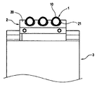
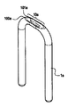
図1に示すように、導熱管1aは、例えばU字形状に構成されたものであって、U字形状に曲がっている部分に、電子発熱デバイスなどの熱源に面と面で接触する蒸発部10aを設けて構成される。この蒸発部10aは、底部にほぼ平坦な受熱面100aを有している。
このような導熱管1aの蒸発部10aは、通常、スタンパー等のプレス加工器具を用いてプレス加工を行うことにより形成される。
図1に示すように、本実施例の導熱管の製造方法は、導熱座を用いて導熱管の蒸発部の平坦化加工を行うのに好適であり、第1の工程(ステップS1)、第2の工程(ステップS2)、第3の工程(ステップS3)及び第4の工程(ステップS4)を含んでいる。
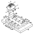
なお、図2に示すように、前記治具3に、作業者が持ちやすいように、側面から延伸する取っ手32を設けても良い。
本実施例では、平台40には、第1の加工部400、第2の加工部401、第3の加工部402および第4の加工部403が設けられている。
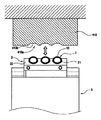
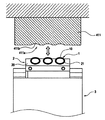
図9は、第1の加工部により、導熱管の蒸発部に対して行われるプレス動作を説明するための説明図、図10は、第2の加工部により、導熱管の蒸発部に対して行われるプレス動作を説明するための説明図、図11は、第3の加工部により、導熱管の蒸発部に対して行われるプレス動作を説明するための説明図、図12は、第4の加工部により、導熱管の蒸発部に対して行われるプレス動作を説明するための説明図である。
なお、図8は、図1に示す導熱管および導熱座を装着した治具をプレス機台上に配置した状態を示す斜視図、図13は、本実施例の製造方法によるプレス機台各工程を完了した状態の導熱管、及び導熱座を装着した治具を示す斜視図である。
2…導熱座、
3…治具、
4…プレス機台、
10…蒸発部、
11…冷却部、
20…底面、
21…溝、
30…穿孔、
31…凹溝、
32…取っ手、
40…平台
41…ポンチ、
100…平坦面、
400…第1の加工部、
401…第2の加工部、
402…第3の加工部、
403…第4の加工部、
404…導孔、
410…第1のスタンパー、
411…第2のスタンパー、
412…第3のスタンパー、
413…第4のスタンパー、
414…導桿、
400a…位置決め突起、
401a…位置決め突起、
402a…位置決め突起、
403a…位置決め突起、
400b…ベリードバイア、
401b…ベリードバイア、
402b…ベリードバイア、
403b…ベリードバイア、
410a…押圧面、
411a…押圧面、
412a…押圧面、
413a…押圧面
410b…凹部、
411b…凹部、
412b…凹部、
S1…第1の工程、
S2…第2の工程、
S3…第3の工程、
S4…第4の工程。
Claims (9)
- 少なくとも一つの導熱管、および前記導熱管に接続される導熱座を設け、前記導熱座の底面に、前記導熱管の蒸発部を配置するための溝を設ける第1の工程と、
前記導熱管の前記蒸発部を前記導熱座の溝内に配置し、治具で固定する第2の工程と、
前記治具が順次配置される第1の加工部、第2の加工部、第3の加工部および第4の加工部を有する平台と、前記平台上方に位置し、間隔を空けて相対するように配置され、前記平台に対してプレスを行い、前記第1の加工部、前記第2の加工部、前記第3の加工部および前記第4の加工部に対応する第1のスタンパー、第2のスタンパー、第3のスタンパーおよび第4のスタンパーをそれぞれ設け、前記第1のスタンパー、前記第2のスタンパー、前記第3のスタンパーおよび前記第4のスタンパーのそれぞれの下表面に押圧面を形成し、前記押圧面は前記第1の加工部、前記第2の加工部、前記第3の加工部に対応して順次徐々に浅くなる凹部をそれぞれ形成し、前記第4のスタンパーの前記押圧面のみが平坦であるポンチと、を含むプレス機台に前記治具を配置する第3の工程と、
前記プレス機台上で前記治具を順次前記各加工部上に配置し、前記各スタンパーが順次前記治具上の前記導熱管の前記蒸発部に対してプレスを行うことにより、前記蒸発部上に平坦面を形成させる第4の工程と、
を含むことを特徴とする導熱管の製造方法。 - 前記第2の工程における前記治具は、前記導熱管の冷却部が貫通する穿孔を有し、前記冷却部が前記穿孔を介して前記治具の底部を貫通することを特徴とする請求項1に記載の導熱管の製造方法。
- 前記第1の加工部、前記第2の加工部、前記第3の加工部および前記第4の加工部は、前記冷却部が貫通するベリードバイアをそれぞれ有することを特徴とする請求項2に記載の導熱管の製造方法。
- 前記導熱管の前記冷却部における前記治具の底部から突出している部分を作業台に押し付けることにより、前記導熱管および前記導熱座が前記治具から外れ、前記治具と前記導熱管および前記導熱座との固定状態を解除する第5の工程を、さらに含むことを特徴とする請求項2に記載の導熱管の製造方法。
- 前記第2の工程における前記治具は、側面から延伸する取っ手を設けていることを特徴とする請求項1に記載の導熱管の製造方法。
- 前記第3の工程における前記プレス機台の前記複数の加工部は、順次配置された前記第1の加工部、前記第2の加工部、前記第3の加工部および前記第4の加工部であり、前記各加工部は横方向に配列されていることを特徴とする請求項1に記載の導熱管の製造方法。
- 前記各加工部は、前記治具の外側の凹溝に接合する位置決め突起を有することを特徴とする請求項6に記載の導熱管の製造方法。
- 前記第3の工程における前記プレス機台の前記複数のスタンパーは、順次設けられた第1のスタンパー、第2のスタンパー、第3のスタンパーおよび第4のスタンパーであって、それぞれ順次前記第1の加工部、前記第2の加工部、前記第3の加工部および前記第4の加工部に対応することを特徴とする請求項6に記載の導熱管の製造方法。
- 前記第3の工程における前記プレス機台の前記ポンチは、下方に延伸する複数の導桿を有し、前記平台上に対応するように設けられた導孔により、所定のプレス距離を一定に維持することを特徴とする請求項1に記載の導熱管の製造方法。
Applications Claiming Priority (2)
| Application Number | Priority Date | Filing Date | Title |
|---|---|---|---|
| TW097138229 | 2008-10-03 | ||
| TW097138229A TW201015041A (en) | 2008-10-03 | 2008-10-03 | Smoothing-manufacture method to bury the heat-pipe evaporating segment into the heat-conduction base |
Publications (2)
| Publication Number | Publication Date |
|---|---|
| JP2010091257A true JP2010091257A (ja) | 2010-04-22 |
| JP5448151B2 JP5448151B2 (ja) | 2014-03-19 |
Family
ID=42074613
Family Applications (1)
| Application Number | Title | Priority Date | Filing Date |
|---|---|---|---|
| JP2009162197A Expired - Fee Related JP5448151B2 (ja) | 2008-10-03 | 2009-07-08 | 導熱管の製造方法 |
Country Status (4)
| Country | Link |
|---|---|
| US (1) | US8161644B2 (ja) |
| JP (1) | JP5448151B2 (ja) |
| KR (1) | KR101130864B1 (ja) |
| TW (1) | TW201015041A (ja) |
Cited By (2)
| Publication number | Priority date | Publication date | Assignee | Title |
|---|---|---|---|---|
| JP2012135784A (ja) * | 2010-12-26 | 2012-07-19 | Noritz Corp | 金属製丸パイプの加工方法およびこの方法を用いて加工された金属製丸パイプ |
| JP2012184913A (ja) * | 2011-03-04 | 2012-09-27 | 崇賢 ▲黄▼ | 放熱装置とその組立方法 |
Families Citing this family (17)
| Publication number | Priority date | Publication date | Assignee | Title |
|---|---|---|---|---|
| US8387250B2 (en) * | 2006-05-12 | 2013-03-05 | Cpumate Inc. | Method for embedding heat pipe into heat-conducting seat |
| US20110000645A1 (en) * | 2009-07-06 | 2011-01-06 | Ping Chen | Heat dissipating board structure and method of manufacturing the same |
| TWI651509B (zh) * | 2011-03-11 | 2019-02-21 | 黃崇賢 | 熱管與導熱座之限位組配結構 |
| TWI656316B (zh) * | 2011-03-11 | 2019-04-11 | 黃崇賢 | Combination method and structure of heat conduction seat for multi-heat pipe tight arrangement |
| US8893384B2 (en) * | 2011-06-28 | 2014-11-25 | Asia Vital Components Co., Ltd. | Heat pipe manufacturing method |
| US20130008629A1 (en) * | 2011-07-05 | 2013-01-10 | Chun-Ming Wu | Thermal module and method of manufacturing same |
| US9895778B2 (en) * | 2015-11-26 | 2018-02-20 | Asia Vital Components Co., Ltd. | Heat dissipation unit manufacturing method |
| KR20180103218A (ko) * | 2017-03-08 | 2018-09-19 | 서울텔레콤 주식회사 | 히트파이프 모듈 및 이의 제조방법 |
| US11375637B2 (en) * | 2017-07-03 | 2022-06-28 | Mitsubishi Electric Corporation | Heat sink |
| CN107968078B (zh) * | 2017-11-14 | 2024-10-11 | 华南理工大学 | 热管嵌入式散热装置及其制造方法 |
| KR102072082B1 (ko) * | 2019-05-09 | 2020-01-31 | 잘만테크 주식회사 | 히트 파이프 및 전열 블록을 포함한 전자부품 냉각장치의 제조방법 |
| US11092386B2 (en) * | 2019-08-21 | 2021-08-17 | Celsia Technologies Taiwan, Inc. | Manufacturing method and structure of heat pipe with adjustable working temperature range |
| USD1009813S1 (en) * | 2019-12-30 | 2024-01-02 | Asia Vital Components Co., Ltd. | Heat pipe |
| CN111970891B (zh) * | 2020-07-10 | 2022-11-15 | 广州龙辉电子科技有限公司 | 水冷板制造方法 |
| TWD213271S (zh) * | 2020-11-05 | 2021-08-11 | 大陸商亞浩電子五金塑膠(惠州)有限公司 | 熱管 |
| CN117677138A (zh) * | 2022-08-31 | 2024-03-08 | 亚浩电子五金塑胶(惠州)有限公司 | 散热装置及其制造方法 |
| CN117583481B (zh) * | 2023-12-05 | 2024-12-03 | 东莞市铨展新能源科技有限公司 | 一种散热器热管滚压专用设备 |
Citations (6)
| Publication number | Priority date | Publication date | Assignee | Title |
|---|---|---|---|---|
| JPH10244399A (ja) * | 1997-03-03 | 1998-09-14 | Honda Motor Co Ltd | プレス装置 |
| JPH11274782A (ja) * | 1998-03-24 | 1999-10-08 | Showa Alum Corp | ヒートパイプ利用放熱器 |
| JP2005291645A (ja) * | 2004-04-01 | 2005-10-20 | Calsonic Kansei Corp | ループ状ヒートパイプ及びその製造方法 |
| JP3119117U (ja) * | 2005-06-24 | 2006-02-16 | ▲るぇ▼新科技股▲ふん▼有限公司 | 熱管散熱器の構造 |
| US20070261244A1 (en) * | 2006-05-12 | 2007-11-15 | Chih-Hung Cheng | Leveling Method for Embedding Heat Pipe in Heat-Conducting Seat |
| EP1921410A1 (en) * | 2006-11-10 | 2008-05-14 | Golden Sun News Techniques Co., Ltd. | Combined assembly of fixing base and heat pipe |
Family Cites Families (8)
| Publication number | Priority date | Publication date | Assignee | Title |
|---|---|---|---|---|
| US8534348B2 (en) * | 2005-09-01 | 2013-09-17 | Molex Incorporated | Heat pipe and method for manufacturing same |
| US8387250B2 (en) * | 2006-05-12 | 2013-03-05 | Cpumate Inc. | Method for embedding heat pipe into heat-conducting seat |
| KR20080001090U (ko) * | 2006-11-09 | 2008-05-15 | 골든 선 뉴스 테크닉스 컴파니 리미티드 | 고정 베이스와 히트 파이프 조합 조립체 |
| TW201017085A (en) * | 2008-10-23 | 2010-05-01 | Golden Sun News Tech Co Ltd | Manufacturing method for heat pipe joining and fixing base and structure thereof |
| CN102159913B (zh) * | 2008-11-04 | 2013-01-16 | 大金工业株式会社 | 冷却构件及其制造方法和制造装置 |
| US20110114293A1 (en) * | 2009-11-16 | 2011-05-19 | Kuo-Len Lin | Manufacturing method, finished product and fixture of coplanar evaporators of multiple heat pipes |
| US8613140B2 (en) * | 2010-06-23 | 2013-12-24 | Shyh-Ming Chen | Heat sink and method for manufacturing the same |
| US20110315365A1 (en) * | 2010-06-23 | 2011-12-29 | Shyh-Ming Chen | Heat sink and method for manufacturing the same |
-
2008
- 2008-10-03 TW TW097138229A patent/TW201015041A/zh not_active IP Right Cessation
-
2009
- 2009-06-03 US US12/477,471 patent/US8161644B2/en not_active Expired - Fee Related
- 2009-06-22 KR KR1020090055354A patent/KR101130864B1/ko not_active Expired - Fee Related
- 2009-07-08 JP JP2009162197A patent/JP5448151B2/ja not_active Expired - Fee Related
Patent Citations (6)
| Publication number | Priority date | Publication date | Assignee | Title |
|---|---|---|---|---|
| JPH10244399A (ja) * | 1997-03-03 | 1998-09-14 | Honda Motor Co Ltd | プレス装置 |
| JPH11274782A (ja) * | 1998-03-24 | 1999-10-08 | Showa Alum Corp | ヒートパイプ利用放熱器 |
| JP2005291645A (ja) * | 2004-04-01 | 2005-10-20 | Calsonic Kansei Corp | ループ状ヒートパイプ及びその製造方法 |
| JP3119117U (ja) * | 2005-06-24 | 2006-02-16 | ▲るぇ▼新科技股▲ふん▼有限公司 | 熱管散熱器の構造 |
| US20070261244A1 (en) * | 2006-05-12 | 2007-11-15 | Chih-Hung Cheng | Leveling Method for Embedding Heat Pipe in Heat-Conducting Seat |
| EP1921410A1 (en) * | 2006-11-10 | 2008-05-14 | Golden Sun News Techniques Co., Ltd. | Combined assembly of fixing base and heat pipe |
Cited By (2)
| Publication number | Priority date | Publication date | Assignee | Title |
|---|---|---|---|---|
| JP2012135784A (ja) * | 2010-12-26 | 2012-07-19 | Noritz Corp | 金属製丸パイプの加工方法およびこの方法を用いて加工された金属製丸パイプ |
| JP2012184913A (ja) * | 2011-03-04 | 2012-09-27 | 崇賢 ▲黄▼ | 放熱装置とその組立方法 |
Also Published As
| Publication number | Publication date |
|---|---|
| TWI371565B (ja) | 2012-09-01 |
| US8161644B2 (en) | 2012-04-24 |
| US20100083500A1 (en) | 2010-04-08 |
| TW201015041A (en) | 2010-04-16 |
| KR20100038132A (ko) | 2010-04-13 |
| KR101130864B1 (ko) | 2012-03-28 |
| JP5448151B2 (ja) | 2014-03-19 |
Similar Documents
| Publication | Publication Date | Title |
|---|---|---|
| JP5448151B2 (ja) | 導熱管の製造方法 | |
| US8387250B2 (en) | Method for embedding heat pipe into heat-conducting seat | |
| US20240066582A1 (en) | Die support mechanism, cylindrical workpiece generation device, and transfer press machine | |
| KR101578015B1 (ko) | Nct 펀칭기 착탈용 부스바 펀칭장치 | |
| KR20110095748A (ko) | 두 개 이상의 유압 펀치가 작동하는 프레스 금형 | |
| JP4913773B2 (ja) | パンチング装置 | |
| JP2018051627A (ja) | 工作物の製造方法、および本方法を実施するための穴開け処理ツール | |
| KR101507284B1 (ko) | 구조 개선된 플라스틱 관 이음부 연결용 클램프 제조장치 및 제조방법 | |
| KR101214869B1 (ko) | 엔진오일 쿨러용 엘리먼트 | |
| CN107716835B (zh) | 分度自对准五金工具 | |
| JP5360841B2 (ja) | パンチプレス機 | |
| CN101716635B (zh) | 将热管蒸发段埋入导热座的平整化制法 | |
| JP4924539B2 (ja) | プレス加工装置、およびプレス加工方法 | |
| KR20200067478A (ko) | 탈착식 프레싱모듈을 포함하는 프레스 어셈블리 | |
| JP3108301U (ja) | 導熱管を備えた放熱装置 | |
| EP2184117B1 (en) | Leveling method for burying evaporating section of heat pipe into thermally conductive seat | |
| TWI512440B (zh) | 散熱裝置及其製造方法 | |
| CN222307893U (zh) | 一种用于散热片的铆压治具 | |
| JP2007149862A (ja) | 金型装置 | |
| JP5782530B2 (ja) | 多工程圧造機 | |
| KR101168574B1 (ko) | 엔진오일 쿨러용 엘리먼트 | |
| JP2008023920A (ja) | 金型コア、金型コアの製造方法、パターン転写金型 | |
| KR20040082865A (ko) | 캐리어 플레이트 제작을 위한 실리콘 천공장치 및 방법 | |
| JP3131334B2 (ja) | 金型装置におけるパンチの研磨再生構造 | |
| CN106890886B (zh) | 一种导热底座的制作方法 |
Legal Events
| Date | Code | Title | Description |
|---|---|---|---|
| A621 | Written request for application examination |
Free format text: JAPANESE INTERMEDIATE CODE: A621 Effective date: 20120326 |
|
| A131 | Notification of reasons for refusal |
Free format text: JAPANESE INTERMEDIATE CODE: A131 Effective date: 20130723 |
|
| A521 | Written amendment |
Free format text: JAPANESE INTERMEDIATE CODE: A523 Effective date: 20131010 |
|
| TRDD | Decision of grant or rejection written | ||
| A01 | Written decision to grant a patent or to grant a registration (utility model) |
Free format text: JAPANESE INTERMEDIATE CODE: A01 Effective date: 20131126 |
|
| A61 | First payment of annual fees (during grant procedure) |
Free format text: JAPANESE INTERMEDIATE CODE: A61 Effective date: 20131220 |
|
| R150 | Certificate of patent or registration of utility model |
Free format text: JAPANESE INTERMEDIATE CODE: R150 |
|
| RD02 | Notification of acceptance of power of attorney |
Free format text: JAPANESE INTERMEDIATE CODE: A7422 Effective date: 20131225 |
|
| RD05 | Notification of revocation of power of attorney |
Free format text: JAPANESE INTERMEDIATE CODE: A7425 Effective date: 20131225 |
|
| LAPS | Cancellation because of no payment of annual fees |