JP2010084635A - 可変動弁装置を備えた内燃機関及び自動二輪車 - Google Patents
可変動弁装置を備えた内燃機関及び自動二輪車 Download PDFInfo
- Publication number
- JP2010084635A JP2010084635A JP2008254872A JP2008254872A JP2010084635A JP 2010084635 A JP2010084635 A JP 2010084635A JP 2008254872 A JP2008254872 A JP 2008254872A JP 2008254872 A JP2008254872 A JP 2008254872A JP 2010084635 A JP2010084635 A JP 2010084635A
- Authority
- JP
- Japan
- Prior art keywords
- rocker arm
- axis
- engine
- hydraulic cylinder
- internal combustion
- Prior art date
- Legal status (The legal status is an assumption and is not a legal conclusion. Google has not performed a legal analysis and makes no representation as to the accuracy of the status listed.)
- Granted
Links
Images


Classifications
-
- F—MECHANICAL ENGINEERING; LIGHTING; HEATING; WEAPONS; BLASTING
- F01—MACHINES OR ENGINES IN GENERAL; ENGINE PLANTS IN GENERAL; STEAM ENGINES
- F01L—CYCLICALLY OPERATING VALVES FOR MACHINES OR ENGINES
- F01L13/00—Modifications of valve-gear to facilitate reversing, braking, starting, changing compression ratio, or other specific operations
- F01L13/0015—Modifications of valve-gear to facilitate reversing, braking, starting, changing compression ratio, or other specific operations for optimising engine performances by modifying valve lift according to various working parameters, e.g. rotational speed, load, torque
- F01L13/0036—Modifications of valve-gear to facilitate reversing, braking, starting, changing compression ratio, or other specific operations for optimising engine performances by modifying valve lift according to various working parameters, e.g. rotational speed, load, torque the valves being driven by two or more cams with different shape, size or timing or a single cam profiled in axial and radial direction
-
- F—MECHANICAL ENGINEERING; LIGHTING; HEATING; WEAPONS; BLASTING
- F01—MACHINES OR ENGINES IN GENERAL; ENGINE PLANTS IN GENERAL; STEAM ENGINES
- F01L—CYCLICALLY OPERATING VALVES FOR MACHINES OR ENGINES
- F01L1/00—Valve-gear or valve arrangements, e.g. lift-valve gear
- F01L1/02—Valve drive
-
- F—MECHANICAL ENGINEERING; LIGHTING; HEATING; WEAPONS; BLASTING
- F01—MACHINES OR ENGINES IN GENERAL; ENGINE PLANTS IN GENERAL; STEAM ENGINES
- F01L—CYCLICALLY OPERATING VALVES FOR MACHINES OR ENGINES
- F01L1/00—Valve-gear or valve arrangements, e.g. lift-valve gear
- F01L1/02—Valve drive
- F01L1/04—Valve drive by means of cams, camshafts, cam discs, eccentrics or the like
- F01L1/047—Camshafts
- F01L1/053—Camshafts overhead type
-
- F—MECHANICAL ENGINEERING; LIGHTING; HEATING; WEAPONS; BLASTING
- F01—MACHINES OR ENGINES IN GENERAL; ENGINE PLANTS IN GENERAL; STEAM ENGINES
- F01L—CYCLICALLY OPERATING VALVES FOR MACHINES OR ENGINES
- F01L1/00—Valve-gear or valve arrangements, e.g. lift-valve gear
- F01L1/26—Valve-gear or valve arrangements, e.g. lift-valve gear characterised by the provision of two or more valves operated simultaneously by same transmitting-gear; peculiar to machines or engines with more than two lift-valves per cylinder
- F01L1/267—Valve-gear or valve arrangements, e.g. lift-valve gear characterised by the provision of two or more valves operated simultaneously by same transmitting-gear; peculiar to machines or engines with more than two lift-valves per cylinder with means for varying the timing or the lift of the valves
-
- F—MECHANICAL ENGINEERING; LIGHTING; HEATING; WEAPONS; BLASTING
- F01—MACHINES OR ENGINES IN GENERAL; ENGINE PLANTS IN GENERAL; STEAM ENGINES
- F01L—CYCLICALLY OPERATING VALVES FOR MACHINES OR ENGINES
- F01L1/00—Valve-gear or valve arrangements, e.g. lift-valve gear
- F01L1/34—Valve-gear or valve arrangements, e.g. lift-valve gear characterised by the provision of means for changing the timing of the valves without changing the duration of opening and without affecting the magnitude of the valve lift
- F01L1/344—Valve-gear or valve arrangements, e.g. lift-valve gear characterised by the provision of means for changing the timing of the valves without changing the duration of opening and without affecting the magnitude of the valve lift changing the angular relationship between crankshaft and camshaft, e.g. using helicoidal gear
- F01L1/3442—Valve-gear or valve arrangements, e.g. lift-valve gear characterised by the provision of means for changing the timing of the valves without changing the duration of opening and without affecting the magnitude of the valve lift changing the angular relationship between crankshaft and camshaft, e.g. using helicoidal gear using hydraulic chambers with variable volume to transmit the rotating force
- F01L2001/34423—Details relating to the hydraulic feeding circuit
- F01L2001/34446—Fluid accumulators for the feeding circuit
-
- Y—GENERAL TAGGING OF NEW TECHNOLOGICAL DEVELOPMENTS; GENERAL TAGGING OF CROSS-SECTIONAL TECHNOLOGIES SPANNING OVER SEVERAL SECTIONS OF THE IPC; TECHNICAL SUBJECTS COVERED BY FORMER USPC CROSS-REFERENCE ART COLLECTIONS [XRACs] AND DIGESTS
- Y10—TECHNICAL SUBJECTS COVERED BY FORMER USPC
- Y10T—TECHNICAL SUBJECTS COVERED BY FORMER US CLASSIFICATION
- Y10T74/00—Machine element or mechanism
- Y10T74/20—Control lever and linkage systems
- Y10T74/20576—Elements
- Y10T74/20882—Rocker arms
-
- Y—GENERAL TAGGING OF NEW TECHNOLOGICAL DEVELOPMENTS; GENERAL TAGGING OF CROSS-SECTIONAL TECHNOLOGIES SPANNING OVER SEVERAL SECTIONS OF THE IPC; TECHNICAL SUBJECTS COVERED BY FORMER USPC CROSS-REFERENCE ART COLLECTIONS [XRACs] AND DIGESTS
- Y10—TECHNICAL SUBJECTS COVERED BY FORMER USPC
- Y10T—TECHNICAL SUBJECTS COVERED BY FORMER US CLASSIFICATION
- Y10T74/00—Machine element or mechanism
- Y10T74/21—Elements
- Y10T74/2101—Cams
- Y10T74/2107—Follower
Landscapes
- Engineering & Computer Science (AREA)
- Mechanical Engineering (AREA)
- General Engineering & Computer Science (AREA)
- Valve Device For Special Equipments (AREA)
- Valve-Gear Or Valve Arrangements (AREA)
- Output Control And Ontrol Of Special Type Engine (AREA)
Abstract
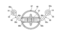
【解決手段】エンジン1は、油圧アクチュエータ65の油圧シリンダ66をカムチェーン室54を横断するように配置し、該油圧シリンダ66内のプランジャの側面から操作子68を出してロッカーアームシャフト14,18を作動させる。エンジン1を搭載した自動二輪車は、油圧アクチュエータ65の外方に車体フレームのフレーム部材が配置される。
【選択図】図17
Description
これは、シリンダヘッドにおける前記ロッカーアームシャフトの一端が臨む一側に、前記ロッカーアームを作動させるための単一のアクチュエータ(ダイヤフラム)が配置され、該アクチュエータのストローク方向に延びるロッドの先端部材が、一対のロッカーアームシャフト上のロッカーアームをスライド移動させるものである。
そこでこの発明は、シリンダヘッドにおけるロッカーアームシャフトの一端が臨む一側にロッカーアーム作動用のアクチュエータを配置する可変動弁装置を備えた内燃機関において、ロッカーアームシャフトの配置によらず単一のアクチュエータでロッカーアームを作動可能とすることを目的とする。また、当該内燃機関を搭載した自動二輪車において、前記アクチュエータを効率よく配置することを目的とする。
また、プランジャの側面から操作子を出すことで、ロッカーアームシャフトの作動を可能とした上で、該ロッカーアームシャフトと油圧シリンダとをそれぞれの軸方向に関して互いにラップさせることができ、油圧アクチュエータのシリンダヘッド外方への突出を抑えることができる。
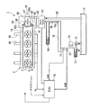
また、油圧シリンダの軸方向視で該油圧シリンダを避けるように油圧切り替えバルブを配置することで、油圧シリンダとの干渉を抑えながら油圧切り替えバルブをシリンダヘッドに近付けることができ、シリンダヘッド周りのさらなる小型化を図ることができる。
図3を参照し、前記カムシャフト11のカム11Aは、前記低速回転域用の左右第一カム15a,16a、及び高速回転域用の左右第二カム15b,16bからなる。すなわち、カムシャフト11は、一気筒当たりに左右第一カム15a,16a及び左右第二カム15b,16bの計四つのカムを有する。
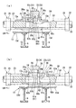
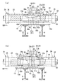
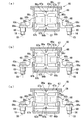
ロッカーアームシャフト14及び各スプリング受けカラー25,26は、エンジン1における運転停止時及び低速回転域を維持しての運転時(低速運転時)には、その軸方向で左方への移動限界位置にある。このとき、ロッカーアーム13は前記第一作動位置にあり(図3(a)参照)、このロッカーアーム13のシャフト挿通ボス13aと前記各スプリング受けカラー25,26との間には、それぞれ各スプリング23,24が所定の初期圧縮がなされた状態で縮設される。
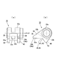
図6を参照し、トリガーアーム33は、支持軸32を挿通する円筒状の基部33aと、該基部33aからロッカーアームシャフト14側に延びる左右係合爪34,35と、該左右係合爪34,35の基端側(基部33a近傍)の間を接続する連結壁33bとを有してなる。
左右突片部43,44は、左右係合爪34,35の下方において該左右係合爪34,35と軸C5方向視でV字状をなすように前記基部33aからロッカーアームシャフト14側に延びるもので、左右係合爪34,35とそれぞれ面一をなす厚板状に設けられ、かつ前記軸C5方向視で左右係合爪34,35よりも延出量の小さい三角形状に形成される。左右突片部43,44は軸C5方向視で互いに同一形状とされる。
図4,5を参照し、トリガーピン37は、前記軸C5方向と直交しかつ各係合溝36a,36b,36c(及び左係合爪34)と同等の軸C5方向幅(厚さ)を有する厚板状のもので、貫通孔62に上方から挿通されて軸C5方向に移動可能かつ軸C5回りに相対回転不能に保持される帯状の挿通部37aと、該挿通部37aの上端側に形成されて挿通部37a及び貫通孔62よりも前記軸C5直交方向での前後幅を広げた拡幅部37bとを有してなる。
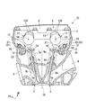
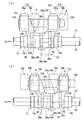
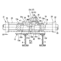
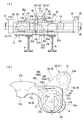
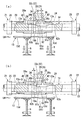
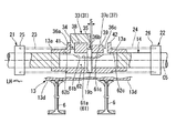
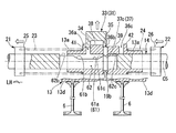
油圧アクチュエータ65は、各ロッカーアームシャフト14,18と軸方向を平行にする油圧シリンダ66を、各ロッカーアームシャフト14,18の間においてシリンダヘッド2右側内のカムチェーン室54を左右に横断させるように配置し、該油圧シリンダ66内のプランジャ67の両側面からは前後一対の操作子68を出し、これら各操作子68を各ロッカーアームシャフト14,18の右端部にそれぞれ係合させることで、前記プランジャ67のストロークに伴い各ロッカーアームシャフト14,18を同時に軸C5方向で移動させる。
なお、符号84はオイル通路79に設けたアキュムレータを、符号85はスプールバルブ81からの油圧戻し通路をそれぞれ示す。また、ECU78には、フェール検知用に気筒毎の吸気管内負圧(PB)の検出情報が入力される。
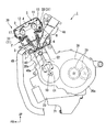
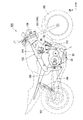
左右メインチューブ111の前部下側からは左右エンジンハンガー112が下方に向けて延び、該左右エンジンハンガー112の下端部にエンジン1の前端部が支持される。なお、エンジン1の後端部は、左右ピボットプレート109の上下に適宜支持される。
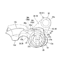
図23を併せて参照し、右エンジンハンガー112は、油圧アクチュエータ65の右側方に配置されており、この右エンジンハンガー112とシリンダヘッド2の右側面との間の比較的左右幅の狭い間隙内に、油圧アクチュエータ65のシリンダヘッド2外側への突出部分(スプールバルブ81含む)が配置されることとなる。
いま、ロッカーアーム13が前記第一作動位置にあり(図4参照)、これを第二作動位置に移動させるべく第一ロッカーアーム移動機構21に所定の力を蓄える際には、まず、ロッカーアーム13がバルブ6を開く前において、前記油圧アクチュエータ65を作動させ、前記左方への移動限界位置にあるロッカーアームシャフト14を各スプリング受けカラー25,26と共に右方へ移動させる(図7(a)参照)。
また、プランジャ67の側面から操作子68を出すことで、ロッカーアームシャフト14,18の作動を可能とした上で、該ロッカーアームシャフト14,18と油圧シリンダ66とをそれぞれの軸方向に関して互いにラップさせることができ、油圧アクチュエータ66のシリンダヘッド2外方への突出を抑えることができる。
また、油圧シリンダ66の軸方向視で該油圧シリンダ66を避けるようにスプールバルブ81を配置することで、油圧シリンダ66との干渉を抑えながらスプールバルブ81をシリンダヘッド2に近付けることができ、シリンダヘッド2周りのさらなる小型化を図ることができる。
この構成によれば、シリンダヘッド2外方への突出を抑えた油圧アクチュエータ65をシリンダヘッド2と車体フレーム105のエンジンハンガー112との間に効率よく配置でき、かつ油圧アクチュエータ65をエンジンハンガー112で側方から覆うことができる。
2 シリンダヘッド
5 動弁装置(動弁系、可変動弁装置)
6 吸気バルブ(機関弁)
7 排気バルブ(機関弁)
13,17 ロッカーアーム
14,18 ロッカーアームシャフト
15a,16a 第一カム
15b,16b 第二カム
54 カムチェーン室
65 油圧アクチュエータ
66 油圧シリンダ
C7 軸線(軸方向)
67 プランジャ
68 操作子
81 スプールバルブ(油圧切り替えバルブ)
C8 軸線(軸方向)
86a,86b エア抜き溝
101 自動二輪車
Claims (7)
- 一機関弁と該機関弁に対する第一及び第二カムとの間にロッカーアームが配置され、該ロッカーアームはロッカーアームシャフトに揺動可能かつ軸方向にスライド移動可能に支持され、前記ロッカーアームシャフトの動きに応じて前記ロッカーアームが前記軸方向にスライド移動することで、該ロッカーアームが前記各カムの何れか一方に択一的に係合して前記機関弁の作動を切り替える可変動弁装置を備えた内燃機関において、
当該内燃機関のシリンダヘッドにおける前記ロッカーアームシャフトの一端が臨む一側に、前記ロッカーアームシャフトを作動させる油圧アクチュエータを配置し、該油圧アクチュエータにおける前記ロッカーアームシャフトと軸方向を平行にする油圧シリンダを前記シリンダヘッドの一側内に設けられたカムチェーン室を横断するように配置し、該油圧シリンダ内のプランジャの側面から操作子を出し、この操作子を前記ロッカーアームシャフトに係合させて該ロッカーアームシャフトを作動させることを特徴とする可変動弁装置を備えた内燃機関。 - 前記ロッカーアームシャフトと前記油圧シリンダとが、前記ロッカーアームシャフトの軸方向に関して互いに重なるように配置されることを特徴とする請求項1に記載の可変動弁装置を備えた内燃機関。
- 一対の前記ロッカーアームシャフトを有し、該各ロッカーアームシャフト間に前記油圧シリンダが配置されることを特徴とする請求項1又は2に記載の可変動弁装置を備えた内燃機関。
- 前記プランジャの両側に前記操作子をそれぞれ配置し、該各操作子が前記各ロッカーアームシャフトをそれぞれ作動させることを特徴とする請求項3に記載の可変動弁装置を備えた内燃機関。
- 前記油圧アクチュエータは、油圧経路を切り替えるプランジャ型の油圧切り替えバルブをさらに備え、この油圧切り替えバルブが、その軸方向を前記油圧シリンダの軸方向と直交させるように配置され、かつ前記油圧シリンダの軸方向視で該油圧シリンダを避けるように配置されることを特徴とする請求項1から4の何れか1項に記載の可変動弁装置を備えた内燃機関。
- 前記プランジャが円筒状に形成され、かつ該プランジャの軸方向がエンジン搭載状態において略水平とされ、このプランジャの上面には、該プランジャが所定のストローク位置にあるときに前記油圧シリンダ内のエアを抜くエア抜き溝が形成されることを特徴とする請求項1から5の何れか1項に記載の可変動弁装置を備えた内燃機関。
- 請求項1から6の何れか1項に記載の内燃機関を搭載した自動二輪車において、
前記油圧アクチュエータの外方に車体フレームのフレーム部材が配置されることを特徴とする自動二輪車。
Priority Applications (4)
| Application Number | Priority Date | Filing Date | Title |
|---|---|---|---|
| JP2008254872A JP5066504B2 (ja) | 2008-09-30 | 2008-09-30 | 可変動弁装置を備えた内燃機関及び自動二輪車 |
| EP09165511A EP2169187B1 (en) | 2008-09-30 | 2009-07-15 | Internal combustion engine equipped with variable valve controlling system and motorcycle |
| DE602009000189T DE602009000189D1 (de) | 2008-09-30 | 2009-07-15 | Verbrennungsmotor mit variablem Ventilsteuerungssystem und Motorrad |
| US12/586,229 US7975662B2 (en) | 2008-09-30 | 2009-09-18 | Internal combustion engine having a hydraulically-actuated variable valve control system, and motorcycle incorporating same |
Applications Claiming Priority (1)
| Application Number | Priority Date | Filing Date | Title |
|---|---|---|---|
| JP2008254872A JP5066504B2 (ja) | 2008-09-30 | 2008-09-30 | 可変動弁装置を備えた内燃機関及び自動二輪車 |
Publications (3)
| Publication Number | Publication Date |
|---|---|
| JP2010084635A true JP2010084635A (ja) | 2010-04-15 |
| JP2010084635A5 JP2010084635A5 (ja) | 2011-06-23 |
| JP5066504B2 JP5066504B2 (ja) | 2012-11-07 |
Family
ID=41051087
Family Applications (1)
| Application Number | Title | Priority Date | Filing Date |
|---|---|---|---|
| JP2008254872A Expired - Fee Related JP5066504B2 (ja) | 2008-09-30 | 2008-09-30 | 可変動弁装置を備えた内燃機関及び自動二輪車 |
Country Status (4)
| Country | Link |
|---|---|
| US (1) | US7975662B2 (ja) |
| EP (1) | EP2169187B1 (ja) |
| JP (1) | JP5066504B2 (ja) |
| DE (1) | DE602009000189D1 (ja) |
Cited By (2)
| Publication number | Priority date | Publication date | Assignee | Title |
|---|---|---|---|---|
| JP2010274761A (ja) * | 2009-05-28 | 2010-12-09 | Honda Motor Co Ltd | 小型車両 |
| JP2018184117A (ja) * | 2017-04-27 | 2018-11-22 | スズキ株式会社 | オイルコントロールバルブユニットの設置構造及び自動二輪車 |
Families Citing this family (22)
| Publication number | Priority date | Publication date | Assignee | Title |
|---|---|---|---|---|
| US9938865B2 (en) | 2008-07-22 | 2018-04-10 | Eaton Corporation | Development of a switching roller finger follower for cylinder deactivation in internal combustion engines |
| US9284859B2 (en) | 2010-03-19 | 2016-03-15 | Eaton Corporation | Systems, methods, and devices for valve stem position sensing |
| US9291075B2 (en) | 2008-07-22 | 2016-03-22 | Eaton Corporation | System to diagnose variable valve actuation malfunctions by monitoring fluid pressure in a control gallery |
| US9228454B2 (en) | 2010-03-19 | 2016-01-05 | Eaton Coporation | Systems, methods and devices for rocker arm position sensing |
| US8985074B2 (en) | 2010-03-19 | 2015-03-24 | Eaton Corporation | Sensing and control of a variable valve actuation system |
| US20190309663A9 (en) | 2008-07-22 | 2019-10-10 | Eaton Corporation | Development of a switching roller finger follower for cylinder deactivation in internal combustion engines |
| US10415439B2 (en) | 2008-07-22 | 2019-09-17 | Eaton Intelligent Power Limited | Development of a switching roller finger follower for cylinder deactivation in internal combustion engines |
| US9708942B2 (en) | 2010-03-19 | 2017-07-18 | Eaton Corporation | Rocker arm assembly and components therefor |
| US9016252B2 (en) | 2008-07-22 | 2015-04-28 | Eaton Corporation | System to diagnose variable valve actuation malfunctions by monitoring fluid pressure in a hydraulic lash adjuster gallery |
| US9581058B2 (en) | 2010-08-13 | 2017-02-28 | Eaton Corporation | Development of a switching roller finger follower for cylinder deactivation in internal combustion engines |
| JP5113007B2 (ja) * | 2008-09-30 | 2013-01-09 | 本田技研工業株式会社 | 可変動弁装置を備えた内燃機関 |
| US9194261B2 (en) | 2011-03-18 | 2015-11-24 | Eaton Corporation | Custom VVA rocker arms for left hand and right hand orientations |
| US11181013B2 (en) | 2009-07-22 | 2021-11-23 | Eaton Intelligent Power Limited | Cylinder head arrangement for variable valve actuation rocker arm assemblies |
| US10087790B2 (en) | 2009-07-22 | 2018-10-02 | Eaton Corporation | Cylinder head arrangement for variable valve actuation rocker arm assemblies |
| US9874122B2 (en) | 2010-03-19 | 2018-01-23 | Eaton Corporation | Rocker assembly having improved durability |
| US9885258B2 (en) | 2010-03-19 | 2018-02-06 | Eaton Corporation | Latch interface for a valve actuating device |
| USD750670S1 (en) | 2013-02-22 | 2016-03-01 | Eaton Corporation | Rocker arm |
| DE112015000034T5 (de) | 2014-03-03 | 2015-11-19 | Eaton Corporation | Ventilbetätigungsvorrichtung und Verfahren zu deren Herstellung |
| JP6389200B2 (ja) * | 2016-03-28 | 2018-09-12 | 本田技研工業株式会社 | 内燃機関の動弁装置 |
| JP6874508B2 (ja) * | 2017-04-27 | 2021-05-19 | スズキ株式会社 | オイルコントロールバルブユニットの設置構造及び自動二輪車 |
| JP6874509B2 (ja) * | 2017-04-27 | 2021-05-19 | スズキ株式会社 | オイルコントロールバルブユニットの設置構造及び自動二輪車 |
| JP6509957B2 (ja) * | 2017-06-30 | 2019-05-08 | 本田技研工業株式会社 | 内燃機関 |
Citations (9)
| Publication number | Priority date | Publication date | Assignee | Title |
|---|---|---|---|---|
| JPS5647202U (ja) * | 1979-09-19 | 1981-04-27 | ||
| JPS56152810U (ja) * | 1980-04-17 | 1981-11-16 | ||
| JPS58190507A (ja) * | 1982-04-30 | 1983-11-07 | Nissan Motor Co Ltd | 内燃機関の可変駆動装置 |
| JPS5919906U (ja) * | 1982-07-27 | 1984-02-07 | 日産自動車株式会社 | 内燃機関の弁作動切換装置 |
| JPS62182945U (ja) * | 1986-05-13 | 1987-11-20 | ||
| JPH055430A (ja) * | 1991-05-17 | 1993-01-14 | Nippondenso Co Ltd | 内燃機関のバルブタイミング調節装置 |
| JP2001058007A (ja) * | 1999-08-20 | 2001-03-06 | Shirouma Science Kk | 薬剤充填済み注射器とピストン |
| JP2004019471A (ja) * | 2002-06-12 | 2004-01-22 | Mitsubishi Motors Corp | 内燃機関の動弁装置 |
| JP2006183642A (ja) * | 2004-12-28 | 2006-07-13 | Yamaha Motor Co Ltd | 車両 |
Family Cites Families (17)
| Publication number | Priority date | Publication date | Assignee | Title |
|---|---|---|---|---|
| US3878822A (en) * | 1974-01-07 | 1975-04-22 | Robert G Beal | Multiple cam mechanism for internal combustion engines |
| JPS54140015A (en) * | 1978-04-21 | 1979-10-30 | Toyota Motor Corp | Variable valve engine |
| JPS5838602B2 (ja) * | 1979-05-09 | 1983-08-24 | トヨタ自動車株式会社 | 可変バルブ機関の制御装置 |
| JPS57188904A (en) | 1981-05-16 | 1982-11-20 | Babcock Hitachi Kk | Recovery boiler for waste heat preventing water hammer |
| US4584974A (en) * | 1982-07-27 | 1986-04-29 | Nissan Motor Co., Ltd. | Valve operation changing system of internal combustion engine |
| JPS61252815A (ja) | 1985-04-30 | 1986-11-10 | Mazda Motor Corp | エンジンの動弁装置 |
| JPS62711A (ja) | 1985-06-26 | 1987-01-06 | Matsushita Electric Ind Co Ltd | 燃焼装置 |
| JPS6218306U (ja) | 1985-07-18 | 1987-02-03 | ||
| JPH0665761B2 (ja) | 1986-02-04 | 1994-08-24 | 東洋紡績株式会社 | ポリエステル系ウレタン弾性糸の製造方法 |
| JPS62184117U (ja) | 1986-05-16 | 1987-11-21 | ||
| JPS62184115U (ja) | 1986-05-16 | 1987-11-21 | ||
| JPS62185810U (ja) | 1986-05-20 | 1987-11-26 | ||
| DE3638087A1 (de) * | 1986-11-07 | 1988-05-11 | Porsche Ag | Vorrichtung zur beeinflussung der steuerzeiten von ventilen |
| US4903651A (en) * | 1987-10-29 | 1990-02-27 | Honda Giken Kogyo Kabushiki Kaisha | Rocker arm clearance removing device |
| EP1905967B1 (en) * | 2006-09-25 | 2009-12-16 | Honda Motor Co., Ltd. | Variable valve lift internal combustion engine |
| JP4741541B2 (ja) * | 2007-03-30 | 2011-08-03 | 本田技研工業株式会社 | エンジンの動弁装置 |
| JP4960753B2 (ja) * | 2007-04-25 | 2012-06-27 | 本田技研工業株式会社 | エンジンの動弁装置 |
-
2008
- 2008-09-30 JP JP2008254872A patent/JP5066504B2/ja not_active Expired - Fee Related
-
2009
- 2009-07-15 DE DE602009000189T patent/DE602009000189D1/de active Active
- 2009-07-15 EP EP09165511A patent/EP2169187B1/en not_active Ceased
- 2009-09-18 US US12/586,229 patent/US7975662B2/en not_active Expired - Fee Related
Patent Citations (9)
| Publication number | Priority date | Publication date | Assignee | Title |
|---|---|---|---|---|
| JPS5647202U (ja) * | 1979-09-19 | 1981-04-27 | ||
| JPS56152810U (ja) * | 1980-04-17 | 1981-11-16 | ||
| JPS58190507A (ja) * | 1982-04-30 | 1983-11-07 | Nissan Motor Co Ltd | 内燃機関の可変駆動装置 |
| JPS5919906U (ja) * | 1982-07-27 | 1984-02-07 | 日産自動車株式会社 | 内燃機関の弁作動切換装置 |
| JPS62182945U (ja) * | 1986-05-13 | 1987-11-20 | ||
| JPH055430A (ja) * | 1991-05-17 | 1993-01-14 | Nippondenso Co Ltd | 内燃機関のバルブタイミング調節装置 |
| JP2001058007A (ja) * | 1999-08-20 | 2001-03-06 | Shirouma Science Kk | 薬剤充填済み注射器とピストン |
| JP2004019471A (ja) * | 2002-06-12 | 2004-01-22 | Mitsubishi Motors Corp | 内燃機関の動弁装置 |
| JP2006183642A (ja) * | 2004-12-28 | 2006-07-13 | Yamaha Motor Co Ltd | 車両 |
Cited By (3)
| Publication number | Priority date | Publication date | Assignee | Title |
|---|---|---|---|---|
| JP2010274761A (ja) * | 2009-05-28 | 2010-12-09 | Honda Motor Co Ltd | 小型車両 |
| JP2018184117A (ja) * | 2017-04-27 | 2018-11-22 | スズキ株式会社 | オイルコントロールバルブユニットの設置構造及び自動二輪車 |
| US11105228B2 (en) | 2017-04-27 | 2021-08-31 | Suzuki Motor Corporation | Mounting structure of oil control valve unit and motorcycle |
Also Published As
| Publication number | Publication date |
|---|---|
| US7975662B2 (en) | 2011-07-12 |
| US20100077978A1 (en) | 2010-04-01 |
| DE602009000189D1 (de) | 2010-10-28 |
| EP2169187A1 (en) | 2010-03-31 |
| JP5066504B2 (ja) | 2012-11-07 |
| EP2169187B1 (en) | 2010-09-15 |
Similar Documents
| Publication | Publication Date | Title |
|---|---|---|
| JP5066504B2 (ja) | 可変動弁装置を備えた内燃機関及び自動二輪車 | |
| JP5113006B2 (ja) | 可変動弁装置を備えた内燃機関 | |
| US7565887B2 (en) | Valve actuation device of internal combustion engine | |
| US7845325B2 (en) | Valve actuating mechanism for an internal combustion engine, and engine incorporating same | |
| JP5113005B2 (ja) | 可変動弁装置を備えた内燃機関 | |
| CN100398787C (zh) | 四冲程发动机的气门传动装置 | |
| JP4960753B2 (ja) | エンジンの動弁装置 | |
| JP5484923B2 (ja) | 可変動弁機構 | |
| JP5113007B2 (ja) | 可変動弁装置を備えた内燃機関 | |
| JP2010084636A (ja) | 内燃機関 | |
| JP4239964B2 (ja) | 内燃機関の動弁装置 | |
| JP2011052546A (ja) | 可変動弁機構 | |
| KR101231349B1 (ko) | 엔진의 가변 밸브 기구 | |
| JP4381965B2 (ja) | 内燃機関 | |
| JP3935184B2 (ja) | Sohc型内燃機関の動弁装置 | |
| JP5775731B2 (ja) | 内燃機関の可変動弁機構 | |
| JP2011179377A (ja) | 可変動弁機構を備えた内燃機関 | |
| JP2005146955A (ja) | 内燃機関の可変動弁装置 | |
| JP2012026364A (ja) | 内燃機関の可変動弁機構 | |
| JP2011179352A (ja) | 可変動弁機構を備えた内燃機関 | |
| JP2012225274A (ja) | 鞍乗り型車両の内燃機関 |
Legal Events
| Date | Code | Title | Description |
|---|---|---|---|
| A521 | Request for written amendment filed |
Free format text: JAPANESE INTERMEDIATE CODE: A523 Effective date: 20110511 |
|
| A621 | Written request for application examination |
Free format text: JAPANESE INTERMEDIATE CODE: A621 Effective date: 20110511 |
|
| A977 | Report on retrieval |
Free format text: JAPANESE INTERMEDIATE CODE: A971007 Effective date: 20120717 |
|
| TRDD | Decision of grant or rejection written | ||
| A01 | Written decision to grant a patent or to grant a registration (utility model) |
Free format text: JAPANESE INTERMEDIATE CODE: A01 Effective date: 20120724 |
|
| A01 | Written decision to grant a patent or to grant a registration (utility model) |
Free format text: JAPANESE INTERMEDIATE CODE: A01 |
|
| A61 | First payment of annual fees (during grant procedure) |
Free format text: JAPANESE INTERMEDIATE CODE: A61 Effective date: 20120813 |
|
| R150 | Certificate of patent or registration of utility model |
Free format text: JAPANESE INTERMEDIATE CODE: R150 Ref document number: 5066504 Country of ref document: JP Free format text: JAPANESE INTERMEDIATE CODE: R150 |
|
| FPAY | Renewal fee payment (event date is renewal date of database) |
Free format text: PAYMENT UNTIL: 20150817 Year of fee payment: 3 |
|
| R250 | Receipt of annual fees |
Free format text: JAPANESE INTERMEDIATE CODE: R250 |
|
| LAPS | Cancellation because of no payment of annual fees |