JP2010068774A - 排藁搬送装置 - Google Patents
排藁搬送装置 Download PDFInfo
- Publication number
- JP2010068774A JP2010068774A JP2008241624A JP2008241624A JP2010068774A JP 2010068774 A JP2010068774 A JP 2010068774A JP 2008241624 A JP2008241624 A JP 2008241624A JP 2008241624 A JP2008241624 A JP 2008241624A JP 2010068774 A JP2010068774 A JP 2010068774A
- Authority
- JP
- Japan
- Prior art keywords
- rail
- waste
- guide rail
- movable
- spring
- Prior art date
- Legal status (The legal status is an assumption and is not a legal conclusion. Google has not performed a legal analysis and makes no representation as to the accuracy of the status listed.)
- Granted
Links
- 239000010902 straw Substances 0.000 title abstract 5
- 239000002699 waste material Substances 0.000 claims description 119
- 230000032258 transport Effects 0.000 claims description 31
- 238000005452 bending Methods 0.000 claims description 4
- 230000000149 penetrating effect Effects 0.000 claims description 2
- 238000010276 construction Methods 0.000 abstract 1
- 235000013339 cereals Nutrition 0.000 description 10
- 230000008602 contraction Effects 0.000 description 10
- 238000009792 diffusion process Methods 0.000 description 4
- 238000000034 method Methods 0.000 description 3
- 230000006835 compression Effects 0.000 description 2
- 238000007906 compression Methods 0.000 description 2
- 238000007781 pre-processing Methods 0.000 description 2
- 238000003466 welding Methods 0.000 description 2
- 238000007599 discharging Methods 0.000 description 1
- 239000000428 dust Substances 0.000 description 1
- 238000003754 machining Methods 0.000 description 1
- 230000002265 prevention Effects 0.000 description 1
- 238000009991 scouring Methods 0.000 description 1
- 238000009333 weeding Methods 0.000 description 1
Images


Landscapes
- Threshing Machine Elements (AREA)
Abstract
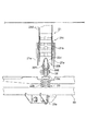
【解決手段】排藁搬送装置20は、後サブレール22dを有する固定レール22Xと、可動レール22Yと、これら固定レール22X及び可動レール22Yに支持されるスプリング22Zとを備えている。該後サブレール22dの直下に、ガイドレール22が収縮状態となるように付勢するスプリング22Zを配置している。これにより、該スプリング22Zに排藁が引っかかることを極力防止できるものでありながら、ガイドレール22の構造を簡素化することができる。
【選択図】図4
Description
前記排藁搬送チェーン(21)及び前記ガイドレール(22)によって排藁を挟持しつつ搬送し、前記ガイドレール(22)を伸長・収縮させることで排藁の搬送先を変更し得る排藁搬送装置(20)において、
前記可動レール(22Y)の直下に配置され、一端部が前記固定レール(22X)に支持されると共に他端部が前記可動レール(22Y)に支持され、前記ガイドレール(22)が収縮状態となるように付勢するスプリング(22Z)を備えてなる、
ことを特徴とする排藁搬送装置(20)にある。
前記可動レール(22Y)は、前記サブレール(22d,22d´)の内径部分に貫通配置されると共に終端部(22g)が下方に折り曲げて形成され、
前記スプリング(22Z)は、前記ガイドレール(22)の収縮状態で前記可動レール(22Y)が貫通配置された前記サブレール(22d,22d´)の直下に配置され、一端部が前記メインレール(22b)の終端部(22h)に支持されると共に他端部が前記可動レールの終端部(22g)に支持されてなる、
ことを特徴とする請求項1記載の排藁搬送装置(20)にある。
ことを特徴とする請求項2記載の排藁搬送装置(20)にある。
21 排藁搬送チェーン
22 ガイドレール
22b メインレール(後メインレール)
22d,22d´ サブレール(後サブレール)
22e,22e´ 庇部
22h メインレールの終端部
22g 可動レールの終端部
22X 固定レール
22Y 可動レール
22Z スプリング
Claims (3)
- 排藁を搬送する排藁搬送チェーンと、該排藁搬送チェーンの下方に配置されると共に固定レール及び可動レールを有するガイドレールと、を備え、
前記排藁搬送チェーン及び前記ガイドレールによって排藁を挟持しつつ搬送し、前記ガイドレールを伸長・収縮させることで排藁の搬送先を変更し得る排藁搬送装置において、
前記可動レールの直下に配置され、一端部が前記固定レールに支持されると共に他端部が前記可動レールに支持され、前記ガイドレールが収縮状態となるように付勢するスプリングを備えてなる、
ことを特徴とする排藁搬送装置。 - 前記固定レールは、断面門形状のメインレールと、前記メインレールの終端部に、該メインレールとの間が連続するように固着され、中空円筒状に形成されたサブレールと、を有し、
前記可動レールは、前記サブレールの内径部分に貫通配置されると共に終端部が下方に折り曲げて形成され、
前記スプリングは、前記ガイドレールの収縮状態で前記可動レールが貫通配置された前記サブレールの直下に配置され、一端部が前記メインレールの終端部に支持されると共に他端部が前記可動レールの終端部に支持されてなる、
ことを特徴とする請求項1記載の排藁搬送装置。 - 前記サブレールの終端部に庇部を備えてなる、
ことを特徴とする請求項2記載の排藁搬送装置。
Priority Applications (1)
| Application Number | Priority Date | Filing Date | Title |
|---|---|---|---|
| JP2008241624A JP5149751B2 (ja) | 2008-09-19 | 2008-09-19 | 排藁搬送装置 |
Applications Claiming Priority (1)
| Application Number | Priority Date | Filing Date | Title |
|---|---|---|---|
| JP2008241624A JP5149751B2 (ja) | 2008-09-19 | 2008-09-19 | 排藁搬送装置 |
Publications (2)
| Publication Number | Publication Date |
|---|---|
| JP2010068774A true JP2010068774A (ja) | 2010-04-02 |
| JP5149751B2 JP5149751B2 (ja) | 2013-02-20 |
Family
ID=42201144
Family Applications (1)
| Application Number | Title | Priority Date | Filing Date |
|---|---|---|---|
| JP2008241624A Expired - Fee Related JP5149751B2 (ja) | 2008-09-19 | 2008-09-19 | 排藁搬送装置 |
Country Status (1)
| Country | Link |
|---|---|
| JP (1) | JP5149751B2 (ja) |
Citations (5)
| Publication number | Priority date | Publication date | Assignee | Title |
|---|---|---|---|---|
| JPS57141747U (ja) * | 1981-02-28 | 1982-09-06 | ||
| JPS63107146U (ja) * | 1986-12-27 | 1988-07-11 | ||
| JPS63114170U (ja) * | 1987-01-19 | 1988-07-22 | ||
| JPS63193422U (ja) * | 1987-05-30 | 1988-12-13 | ||
| JPH1052159A (ja) * | 1996-08-09 | 1998-02-24 | Kubota Corp | コンバインの排ワラ搬送装置 |
-
2008
- 2008-09-19 JP JP2008241624A patent/JP5149751B2/ja not_active Expired - Fee Related
Patent Citations (5)
| Publication number | Priority date | Publication date | Assignee | Title |
|---|---|---|---|---|
| JPS57141747U (ja) * | 1981-02-28 | 1982-09-06 | ||
| JPS63107146U (ja) * | 1986-12-27 | 1988-07-11 | ||
| JPS63114170U (ja) * | 1987-01-19 | 1988-07-22 | ||
| JPS63193422U (ja) * | 1987-05-30 | 1988-12-13 | ||
| JPH1052159A (ja) * | 1996-08-09 | 1998-02-24 | Kubota Corp | コンバインの排ワラ搬送装置 |
Also Published As
| Publication number | Publication date |
|---|---|
| JP5149751B2 (ja) | 2013-02-20 |
Similar Documents
| Publication | Publication Date | Title |
|---|---|---|
| JP5149751B2 (ja) | 排藁搬送装置 | |
| JPH10215648A (ja) | コンバインの脱穀装置 | |
| JP2008295395A (ja) | コンバイン | |
| JP2010273591A (ja) | コンバイン | |
| JP6733109B2 (ja) | 脱穀装置 | |
| JP2007014287A (ja) | コンバイン | |
| JP2005176726A (ja) | コンバイン | |
| JP2002191222A (ja) | コンバインの穀稈搬送装置 | |
| JP5129580B2 (ja) | コンバイン | |
| CN108990518B (zh) | 联合收割机 | |
| WO2007148719A1 (ja) | コンバイン | |
| JP7179142B2 (ja) | コンバイン | |
| JP2002112614A (ja) | 自脱型コンバイン | |
| JP7142553B2 (ja) | 汎用コンバイン | |
| JP2025038718A (ja) | コンバイン | |
| JPH099777A (ja) | 脱穀機における排藁搬送装置 | |
| CN108990512B (zh) | 联合收割机 | |
| JP2009247235A (ja) | コンバイン | |
| JP2007174955A (ja) | コンバイン | |
| JP2000023547A (ja) | コンバインの脱穀機 | |
| JP3369792B2 (ja) | 脱穀機における排藁搬送装置 | |
| JP2007075010A (ja) | コンバイン | |
| JP3369753B2 (ja) | 脱穀機における排藁搬送装置 | |
| JP5209373B2 (ja) | コンバインの排藁放出装置 | |
| JPH119076A (ja) | 農作業車の脱穀排稈装置 |
Legal Events
| Date | Code | Title | Description |
|---|---|---|---|
| A621 | Written request for application examination |
Free format text: JAPANESE INTERMEDIATE CODE: A621 Effective date: 20110802 |
|
| A977 | Report on retrieval |
Free format text: JAPANESE INTERMEDIATE CODE: A971007 Effective date: 20120822 |
|
| A131 | Notification of reasons for refusal |
Free format text: JAPANESE INTERMEDIATE CODE: A131 Effective date: 20120828 |
|
| A521 | Written amendment |
Free format text: JAPANESE INTERMEDIATE CODE: A523 Effective date: 20121025 |
|
| TRDD | Decision of grant or rejection written | ||
| A01 | Written decision to grant a patent or to grant a registration (utility model) |
Free format text: JAPANESE INTERMEDIATE CODE: A01 Effective date: 20121113 |
|
| A61 | First payment of annual fees (during grant procedure) |
Free format text: JAPANESE INTERMEDIATE CODE: A61 Effective date: 20121130 |
|
| FPAY | Renewal fee payment (event date is renewal date of database) |
Free format text: PAYMENT UNTIL: 20151207 Year of fee payment: 3 |
|
| LAPS | Cancellation because of no payment of annual fees |