JP2010057258A - 電気接続箱 - Google Patents
電気接続箱 Download PDFInfo
- Publication number
- JP2010057258A JP2010057258A JP2008218975A JP2008218975A JP2010057258A JP 2010057258 A JP2010057258 A JP 2010057258A JP 2008218975 A JP2008218975 A JP 2008218975A JP 2008218975 A JP2008218975 A JP 2008218975A JP 2010057258 A JP2010057258 A JP 2010057258A
- Authority
- JP
- Japan
- Prior art keywords
- electrolytic capacitor
- junction box
- support portion
- wiring board
- printed wiring
- Prior art date
- Legal status (The legal status is an assumption and is not a legal conclusion. Google has not performed a legal analysis and makes no representation as to the accuracy of the status listed.)
- Granted
Links
Images


Landscapes
- Connection Or Junction Boxes (AREA)
Abstract
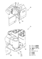
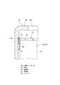
【解決手段】ロアケースとアッパケース32の中にプリント回路板21が内蔵された電気接続箱であって、前記プリント回路板21には、電解コンデンサ23aがプリント配線板22から浮いた状態で立てて実装され、前記アッパケース32における前記電解コンデンサ23aに対応する部位には、該電解コンデンサ23aを覆う収容部33が設けられる。そして、該収容部33に、内側に収容する電解コンデンサ23aの外周面に弾力的に接して電解コンデンサ23aを支持する支持部34が一体に形成された電気接続箱11。
【選択図】図2
Description
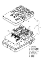
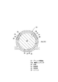
図1は、車両用の電気接続箱11の分解斜視図であり、この図に示すように電気接続箱11は、薄い箱状をなし、プリント回路板21がハウジングとしてのロアケース31とアッパケース32の中に内蔵されて構成される。
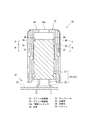
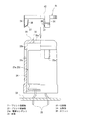
電解コンデンサ23aは、円筒状をなす本体24に、本体24の底面から延びる2本のリード線25,25を有した形態であり、これらリード線25,25がプリント配線板22にハンダ付けされて実装される。実装にあたっては、電解コンデンサ23aの本体24がプリント配線板22の上面から浮くようにハンダ付けされる(図4参照)。これは、プリント配線板22を介して伝わる熱による悪影響を回避するためである。つまり、熱による悪影響を回避できるように、必要な高さ、例えば数ミリメートル浮かせた状態に実装する。
この発明のハウジングは、前記のロアケース31及びアッパケース32に対応し、
縦長形状の電気部品は、電解コンデンサ23aに対応するも、
この発明は前記の構成のみに限定されるものではなく、その他の形態を採用することもできる。
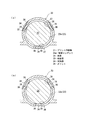
また、収容部は、キャップ状に限らず、収容する電気部品の形態に応じて筒状など適宜の形態に形成できる。
21…プリント回路板
22…プリント配線板
23a…電解コンデンサ
24…本体
31…ロアケース
32…アッパケース
33…収容部
34…支持部
36…スリット
Claims (5)
- ハウジング内にプリント回路板が内蔵された電気接続箱であって、
前記プリント回路板には、縦長形状の電気部品が立てた状態で、かつ電気部品の本体がプリント配線板から離れて実装され、
前記ハウジングにおける前記縦長形状の電気部品に対応する部位には、該電気部品を覆う収容部が設けられ、
該収容部に、内側に収容する電気部品の外周面に接して電気部品を支持する支持部が備えられた
電気接続箱。 - 前記支持部が、電気部品に対して弾性的に接する付勢力を有した
請求項1に記載の電気接続箱。 - 前記支持部が収容部に一体成形されたものである
請求項1または請求項2に記載の電気接続箱。 - 前記収容部に2本一組のスリットが複数形成されるとともに、
これらスリットの間を内周側に迫り出させて、前記支持部が形成された
請求項3に記載の電気接続箱。 - 前記支持部が金属製の板ばねで形成された
請求項1または請求項2に記載の電気接続箱。
Priority Applications (1)
| Application Number | Priority Date | Filing Date | Title |
|---|---|---|---|
| JP2008218975A JP5242297B2 (ja) | 2008-08-28 | 2008-08-28 | 電気接続箱 |
Applications Claiming Priority (1)
| Application Number | Priority Date | Filing Date | Title |
|---|---|---|---|
| JP2008218975A JP5242297B2 (ja) | 2008-08-28 | 2008-08-28 | 電気接続箱 |
Publications (2)
| Publication Number | Publication Date |
|---|---|
| JP2010057258A true JP2010057258A (ja) | 2010-03-11 |
| JP5242297B2 JP5242297B2 (ja) | 2013-07-24 |
Family
ID=42072596
Family Applications (1)
| Application Number | Title | Priority Date | Filing Date |
|---|---|---|---|
| JP2008218975A Active JP5242297B2 (ja) | 2008-08-28 | 2008-08-28 | 電気接続箱 |
Country Status (1)
| Country | Link |
|---|---|
| JP (1) | JP5242297B2 (ja) |
Cited By (3)
| Publication number | Priority date | Publication date | Assignee | Title |
|---|---|---|---|---|
| JP2014135787A (ja) * | 2013-01-08 | 2014-07-24 | Sumitomo Wiring Syst Ltd | 電気接続箱 |
| JP2016115883A (ja) * | 2014-12-17 | 2016-06-23 | 日信工業株式会社 | 電子制御ユニット |
| JP2017175735A (ja) * | 2016-03-22 | 2017-09-28 | 株式会社デンソー | 乗員保護装置用ecu |
Citations (3)
| Publication number | Priority date | Publication date | Assignee | Title |
|---|---|---|---|---|
| JPH077181U (ja) * | 1993-06-29 | 1995-01-31 | 松下電工株式会社 | 電子部品の実装構造 |
| JP2001244660A (ja) * | 2000-03-01 | 2001-09-07 | Sumitomo Wiring Syst Ltd | 電気接続箱 |
| JP2002185165A (ja) * | 2000-12-19 | 2002-06-28 | Sony Corp | 電気部品の実装装置 |
-
2008
- 2008-08-28 JP JP2008218975A patent/JP5242297B2/ja active Active
Patent Citations (3)
| Publication number | Priority date | Publication date | Assignee | Title |
|---|---|---|---|---|
| JPH077181U (ja) * | 1993-06-29 | 1995-01-31 | 松下電工株式会社 | 電子部品の実装構造 |
| JP2001244660A (ja) * | 2000-03-01 | 2001-09-07 | Sumitomo Wiring Syst Ltd | 電気接続箱 |
| JP2002185165A (ja) * | 2000-12-19 | 2002-06-28 | Sony Corp | 電気部品の実装装置 |
Cited By (5)
| Publication number | Priority date | Publication date | Assignee | Title |
|---|---|---|---|---|
| JP2014135787A (ja) * | 2013-01-08 | 2014-07-24 | Sumitomo Wiring Syst Ltd | 電気接続箱 |
| JP2016115883A (ja) * | 2014-12-17 | 2016-06-23 | 日信工業株式会社 | 電子制御ユニット |
| CN105711573A (zh) * | 2014-12-17 | 2016-06-29 | 日信工业株式会社 | 电子控制单元 |
| US9899983B2 (en) | 2014-12-17 | 2018-02-20 | Autoliv Nissin Brake Systems Japan Co., Ltd. | Electronic control unit |
| JP2017175735A (ja) * | 2016-03-22 | 2017-09-28 | 株式会社デンソー | 乗員保護装置用ecu |
Also Published As
| Publication number | Publication date |
|---|---|
| JP5242297B2 (ja) | 2013-07-24 |
Similar Documents
| Publication | Publication Date | Title |
|---|---|---|
| CN101322305B (zh) | 用于驱动镜头的马达 | |
| EP2665165B1 (en) | Motor for driving lenses | |
| JP5459191B2 (ja) | 電圧変換装置 | |
| KR20080090301A (ko) | 압력 접촉을 구현하는 전력용 반도체 모듈과 그 제조방법 | |
| US8764419B2 (en) | Fuel pump module for damping vibration | |
| US20120276757A1 (en) | Shield and circuit board module having the same | |
| JP2014187100A (ja) | 電子装置 | |
| JP5242297B2 (ja) | 電気接続箱 | |
| JP5979363B2 (ja) | 照明器具 | |
| JP5884137B2 (ja) | 電気接続箱 | |
| JP2020131999A (ja) | 電子モジュール | |
| JP7264002B2 (ja) | 電気接続箱 | |
| JP2023001851A (ja) | バスバカバーおよびバスバの配索構造 | |
| JP6745228B2 (ja) | 電子制御装置 | |
| JP6037850B2 (ja) | グロメット | |
| JP6597676B2 (ja) | 発光装置 | |
| JP5483728B2 (ja) | コイル保持構造 | |
| JP7200481B2 (ja) | 電子装置 | |
| KR101940256B1 (ko) | 커패시터 하우징 | |
| JP2021150150A (ja) | 端子用キャップ | |
| JP6742469B1 (ja) | 燃料供給装置 | |
| KR101699433B1 (ko) | 차량용 실내등에 사용되는 엘이디 램프장치 | |
| CN216048140U (zh) | 一种雾化片连接线的保护装置及新型加湿器 | |
| JP4924973B2 (ja) | カメラモジュールソケット | |
| JP2018112138A (ja) | 燃料タンク蓋ユニット |
Legal Events
| Date | Code | Title | Description |
|---|---|---|---|
| A621 | Written request for application examination |
Free format text: JAPANESE INTERMEDIATE CODE: A621 Effective date: 20110601 |
|
| A977 | Report on retrieval |
Free format text: JAPANESE INTERMEDIATE CODE: A971007 Effective date: 20121128 |
|
| A131 | Notification of reasons for refusal |
Free format text: JAPANESE INTERMEDIATE CODE: A131 Effective date: 20121225 |
|
| A521 | Written amendment |
Free format text: JAPANESE INTERMEDIATE CODE: A523 Effective date: 20130215 |
|
| TRDD | Decision of grant or rejection written | ||
| A01 | Written decision to grant a patent or to grant a registration (utility model) |
Free format text: JAPANESE INTERMEDIATE CODE: A01 Effective date: 20130312 |
|
| A61 | First payment of annual fees (during grant procedure) |
Free format text: JAPANESE INTERMEDIATE CODE: A61 Effective date: 20130403 |
|
| FPAY | Renewal fee payment (event date is renewal date of database) |
Free format text: PAYMENT UNTIL: 20160412 Year of fee payment: 3 |
|
| R151 | Written notification of patent or utility model registration |
Ref document number: 5242297 Country of ref document: JP Free format text: JAPANESE INTERMEDIATE CODE: R151 |
|
| FPAY | Renewal fee payment (event date is renewal date of database) |
Free format text: PAYMENT UNTIL: 20160412 Year of fee payment: 3 |
|
| S531 | Written request for registration of change of domicile |
Free format text: JAPANESE INTERMEDIATE CODE: R313531 |
|
| R350 | Written notification of registration of transfer |
Free format text: JAPANESE INTERMEDIATE CODE: R350 |