JP2010056947A - 通過時間固定装置 - Google Patents
通過時間固定装置 Download PDFInfo
- Publication number
- JP2010056947A JP2010056947A JP2008220315A JP2008220315A JP2010056947A JP 2010056947 A JP2010056947 A JP 2010056947A JP 2008220315 A JP2008220315 A JP 2008220315A JP 2008220315 A JP2008220315 A JP 2008220315A JP 2010056947 A JP2010056947 A JP 2010056947A
- Authority
- JP
- Japan
- Prior art keywords
- frame
- delay
- synchronization
- time
- control circuit
- Prior art date
- Legal status (The legal status is an assumption and is not a legal conclusion. Google has not performed a legal analysis and makes no representation as to the accuracy of the status listed.)
- Granted
Links
Images


Classifications
-
- H—ELECTRICITY
- H04—ELECTRIC COMMUNICATION TECHNIQUE
- H04J—MULTIPLEX COMMUNICATION
- H04J3/00—Time-division multiplex systems
- H04J3/02—Details
- H04J3/06—Synchronising arrangements
- H04J3/0635—Clock or time synchronisation in a network
- H04J3/0638—Clock or time synchronisation among nodes; Internode synchronisation
- H04J3/0658—Clock or time synchronisation among packet nodes
-
- H—ELECTRICITY
- H02—GENERATION; CONVERSION OR DISTRIBUTION OF ELECTRIC POWER
- H02H—EMERGENCY PROTECTIVE CIRCUIT ARRANGEMENTS
- H02H1/00—Details of emergency protective circuit arrangements
- H02H1/0061—Details of emergency protective circuit arrangements concerning transmission of signals
- H02H1/0084—Details of emergency protective circuit arrangements concerning transmission of signals by means of pilot wires or a telephone network; watching of these wires
-
- H—ELECTRICITY
- H04—ELECTRIC COMMUNICATION TECHNIQUE
- H04J—MULTIPLEX COMMUNICATION
- H04J3/00—Time-division multiplex systems
- H04J3/02—Details
- H04J3/06—Synchronising arrangements
- H04J3/0635—Clock or time synchronisation in a network
- H04J3/0638—Clock or time synchronisation among nodes; Internode synchronisation
- H04J3/0658—Clock or time synchronisation among packet nodes
- H04J3/0673—Clock or time synchronisation among packet nodes using intermediate nodes, e.g. modification of a received timestamp before further transmission to the next packet node, e.g. including internal delay time or residence time into the packet
-
- H—ELECTRICITY
- H02—GENERATION; CONVERSION OR DISTRIBUTION OF ELECTRIC POWER
- H02H—EMERGENCY PROTECTIVE CIRCUIT ARRANGEMENTS
- H02H3/00—Emergency protective circuit arrangements for automatic disconnection directly responsive to an undesired change from normal electric working condition with or without subsequent reconnection ; integrated protection
- H02H3/26—Emergency protective circuit arrangements for automatic disconnection directly responsive to an undesired change from normal electric working condition with or without subsequent reconnection ; integrated protection responsive to difference between voltages or between currents; responsive to phase angle between voltages or between currents
- H02H3/28—Emergency protective circuit arrangements for automatic disconnection directly responsive to an undesired change from normal electric working condition with or without subsequent reconnection ; integrated protection responsive to difference between voltages or between currents; responsive to phase angle between voltages or between currents involving comparison of the voltage or current values at two spaced portions of a single system, e.g. at opposite ends of one line, at input and output of apparatus
- H02H3/30—Emergency protective circuit arrangements for automatic disconnection directly responsive to an undesired change from normal electric working condition with or without subsequent reconnection ; integrated protection responsive to difference between voltages or between currents; responsive to phase angle between voltages or between currents involving comparison of the voltage or current values at two spaced portions of a single system, e.g. at opposite ends of one line, at input and output of apparatus using pilot wires or other signalling channel
- H02H3/305—Emergency protective circuit arrangements for automatic disconnection directly responsive to an undesired change from normal electric working condition with or without subsequent reconnection ; integrated protection responsive to difference between voltages or between currents; responsive to phase angle between voltages or between currents involving comparison of the voltage or current values at two spaced portions of a single system, e.g. at opposite ends of one line, at input and output of apparatus using pilot wires or other signalling channel involving current comparison
-
- H—ELECTRICITY
- H04—ELECTRIC COMMUNICATION TECHNIQUE
- H04J—MULTIPLEX COMMUNICATION
- H04J3/00—Time-division multiplex systems
- H04J3/02—Details
- H04J3/06—Synchronising arrangements
- H04J3/062—Synchronisation of signals having the same nominal but fluctuating bit rates, e.g. using buffers
-
- H—ELECTRICITY
- H04—ELECTRIC COMMUNICATION TECHNIQUE
- H04J—MULTIPLEX COMMUNICATION
- H04J3/00—Time-division multiplex systems
- H04J3/02—Details
- H04J3/06—Synchronising arrangements
- H04J3/0635—Clock or time synchronisation in a network
- H04J3/0682—Clock or time synchronisation in a network by delay compensation, e.g. by compensation of propagation delay or variations thereof, by ranging
Landscapes
- Engineering & Computer Science (AREA)
- Computer Networks & Wireless Communication (AREA)
- Signal Processing (AREA)
- Physics & Mathematics (AREA)
- Electromagnetism (AREA)
- Small-Scale Networks (AREA)
- Synchronisation In Digital Transmission Systems (AREA)
- Data Exchanges In Wide-Area Networks (AREA)
Abstract
【解決手段】クライアント3(1)からのフレーム101は、ポートであるPHY22(1)を通じて通過時間固定装置2に送信される。制御回路25中のフレーム種別判定手段25aが、クライアント3(1)から送られたフレーム101のフレーム種別を判定する。宛先判定手段25bは、受信したフレーム101から宛先アドレスを取得することで、遅延指令の対象となるフレーム制御回路23(n+1)を特定する。同期フレームと判定されたフレーム101は、特定されたフレーム制御回路23(n+1)において一定時間遅延手段26aにより一定時間遅延する。
【選択図】図1
Description
電気学会発行「保護リレーシステム工学」
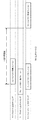
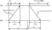
まず、クライアント3(1)が、ケーブル31(1−1)上に宛先をサーバ4としたフレーム101を送信し、その直後に、クライアント3(2)がケーブル31(2−1)上に宛先をサーバ4としたフレーム102を送信する。この際のケーブル上におけるフレームの送信タイミングを示したタイムチャート1は、図10の通りである。
[1.1.全体構成]
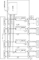
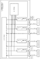
次に、本実施形態に係る構成について図1を参照して以下に説明する。
図1に示す通り、本実施形態の全体構成として、イーサネットスイッチ1と、クライアント3(1)〜クライアント3(n)及びサーバ4とが、本発明部分である通過時間固定装置2を介して繋がれている。ここで、クライアント3(1)〜クライアント3(n)及びサーバ4には、ネットワークインターフェイスハードウエアを備えた電流差動保護継電器装置等の一般的なものを採用している。
次に、クライアント3(1)〜クライアント3(n)やサーバ4からのフレームの通過時間を固定する通過時間固定装置2の具体的な構成を詳述する。
図1の通り、通過時間固定装置2は、信号線27(1−1)〜(n+1)、(2−1)〜(2−n+1)を監視し、イーサネットスイッチ1、クライアント3(1)〜3(n)及びサーバ4から送信された同期フレームの検出を行う判定回路24を備えている。
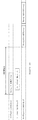
次に、上記のような構成を有する本実施形態に係る通過時間固定装置2の第1の動作例を以下に説明する。なお、フレーム101やフレーム102などのクライアント3から送信するフレーム構成1は、例えば、図11の通り、宛先アドレス、送信元アドレス、フレーム種別、データ部、FCS(チェックコード)から成る。
まず、図3に示すタイムチャート2のタイミングでクライアント3(1)からのフレーム101は、ポートであるPHY22(1)を通じて通過時間固定装置2に送信される。
(規格上の最大フレーム長+α)*伝送時間
但し、この遅延時間として最大遅延時間を固定しても構わない。
Gbpsの場合の遅延時間は次の通りである。
(8000バイト * 8ビット)/1G = 64μs
次に、上記構成を有する通過時間固定装置2の第2の動作例を図5に示すタイムチャート3を参照して以下に説明する。なお、第2の動作例では、クライアント3(2)からの一般フレーム102、クライアント3(1)からの同期フレーム101の順にフレームが通過時間固定装置2に送信される場合の動作手順について説明する。
次に、通過時間固定装置2の第3の動作例について図6のタイムチャート4を参照して以下に説明する。なお、第3の動作例では、クライアント3(1)からの同期フレーム101、クライアント3(2)からの一般フレーム102の順に通過時間固定装置2に送信する場合の動作手順について説明する。
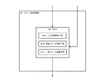
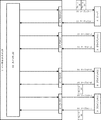
なお、本発明は、上記のような実施形態に限定されるものではなく、下記のような実施形態も包含する。すなわち、図7に示す通り、上記で示したような通過時間固定装置2の判定回路24及びフレーム制御回路23の構成をイーサネットスイッチ1内に採用する実施形態も本発明は包含する。これにより、イーサネットスイッチ1単独で高精度なサンプリング時刻の同期制御が可能となる。
2…通過時間固定装置
3…クライアント
4…サーバ
21…PHY(1)〜(n+1)
22…PHY(1)〜(n+1)
23…フレーム制御回路
24…判定回路
25…制御回路
25a…フレーム種別判定手段
25b…宛先判定手段
26…FIFO
26a…一定時間遅延手段
26b…遅延フレーム判定手段
26c…一般フレーム待機手段
27…信号線(1−1)〜(n+1)、(2−1)〜(2−n+1)
31…ケーブル(1−1)〜(1−n)、(2−1)〜(2−n+1)
41…PHY(1)〜(n+1)
70c…一般フレーム待機手段
101…フレーム(同期フレーム)
102…フレーム(一般フレーム)
Claims (5)
- 保護継電装置が各々設けられた各端子からの電流情報に基づいて当該各端子を繋ぐ送電線を保護するために、ネットワークを介して前記端子間のサンプリング同期を行い、当該端子間の伝送遅延時間を制御する通過時間固定装置であって、
前記各端子からの電流情報を含む各種情報から構成されるフレームが相手端子との関係で同期フレームであるかを判定するフレーム種別判定手段と、
前記フレーム種別判定手段により判定された同期フレームの相手端子への伝送を一定時間遅延させる一定時間遅延手段と、
を備えることを特徴とする通過時間固定装置。 - 前記一定時間遅延手段は、前記保護継電器毎に各々設けられていることを特徴とする請求項1に記載の通過時間固定装置。
- 前記フレームは、対象とする前記一定時間遅延手段を特定するための宛先アドレス情報を含み、
前記宛先アドレス情報に基づいて前記フレーム毎に前記一定時間遅延手段を特定する宛先特定手段を備えることを特徴とする請求項1又は2に記載の通過時間固定装置。 - 前記一定時間遅延手段により遅延中である前記同期フレームが存在するかを判定する遅延フレーム判定手段と、
前記遅延フレーム判定手段により遅延中の前記同期フレームが存在すると判定された場合に、前記フレーム種別判定手段により同期フレームでないと判定されたフレームを遅延させる遅延手段と、
を備えることを特徴とする請求項1〜3のいずれか1項に記載の通過時間固定装置。 - 前記遅延手段は、前記同期フレームの遅延が完了するまで遅延させることを特徴とする請求項4に記載の通過時間固定装置。
Priority Applications (5)
| Application Number | Priority Date | Filing Date | Title |
|---|---|---|---|
| JP2008220315A JP5249682B2 (ja) | 2008-08-28 | 2008-08-28 | 保護継電装置用通過時間固定装置 |
| US13/061,346 US8599883B2 (en) | 2008-08-28 | 2009-08-28 | Transit time fixation device |
| PCT/JP2009/004243 WO2010023955A1 (ja) | 2008-08-28 | 2009-08-28 | 通過時間固定装置 |
| CN200980133725.5A CN102138302B (zh) | 2008-08-28 | 2009-08-28 | 经过时间固定装置 |
| EP09809610.0A EP2320602B1 (en) | 2008-08-28 | 2009-08-28 | Transit time fixation device |
Applications Claiming Priority (1)
| Application Number | Priority Date | Filing Date | Title |
|---|---|---|---|
| JP2008220315A JP5249682B2 (ja) | 2008-08-28 | 2008-08-28 | 保護継電装置用通過時間固定装置 |
Related Child Applications (1)
| Application Number | Title | Priority Date | Filing Date |
|---|---|---|---|
| JP2013083028A Division JP2013141319A (ja) | 2013-04-11 | 2013-04-11 | 保護継電システム及び保護継電システムの通過時間固定方法 |
Publications (2)
| Publication Number | Publication Date |
|---|---|
| JP2010056947A true JP2010056947A (ja) | 2010-03-11 |
| JP5249682B2 JP5249682B2 (ja) | 2013-07-31 |
Family
ID=41721136
Family Applications (1)
| Application Number | Title | Priority Date | Filing Date |
|---|---|---|---|
| JP2008220315A Expired - Fee Related JP5249682B2 (ja) | 2008-08-28 | 2008-08-28 | 保護継電装置用通過時間固定装置 |
Country Status (5)
| Country | Link |
|---|---|
| US (1) | US8599883B2 (ja) |
| EP (1) | EP2320602B1 (ja) |
| JP (1) | JP5249682B2 (ja) |
| CN (1) | CN102138302B (ja) |
| WO (1) | WO2010023955A1 (ja) |
Cited By (5)
| Publication number | Priority date | Publication date | Assignee | Title |
|---|---|---|---|---|
| JP2013074340A (ja) * | 2011-09-26 | 2013-04-22 | Fujitsu Ltd | 中継装置及び中継方法 |
| JP2013162254A (ja) * | 2012-02-03 | 2013-08-19 | Nec Corp | 中継装置、中継装置制御方法、及び、中継装置制御プログラム |
| WO2014083628A1 (ja) * | 2012-11-28 | 2014-06-05 | 三菱電機株式会社 | 中継装置及び通信システム及び中継方法 |
| WO2014112264A1 (ja) | 2013-01-15 | 2014-07-24 | 株式会社 東芝 | 保護継電システムおよび保護継電装置 |
| JP2020155942A (ja) * | 2019-03-20 | 2020-09-24 | 三菱電機株式会社 | 保護制御装置 |
Families Citing this family (7)
| Publication number | Priority date | Publication date | Assignee | Title |
|---|---|---|---|---|
| JP5475551B2 (ja) * | 2010-05-28 | 2014-04-16 | 株式会社東芝 | 保護継電装置 |
| KR20150113049A (ko) * | 2013-02-27 | 2015-10-07 | 미쓰비시덴키 가부시키가이샤 | 중계 장치, 중계 방법 및 중계 프로그램을 기록한 컴퓨터 판독 가능한 기록 매체 |
| WO2016132539A1 (ja) * | 2015-02-20 | 2016-08-25 | 三菱電機株式会社 | 通信装置及び通信システム及び通信方法 |
| WO2016147405A1 (ja) * | 2015-03-19 | 2016-09-22 | 三菱電機株式会社 | 通信装置およびネットワークシステム |
| CN105119376B (zh) * | 2015-09-09 | 2017-08-22 | 许继集团有限公司 | 一种基于常规采样goose跳闸模式的采样实现方法及装置 |
| CN105958469B (zh) * | 2016-06-15 | 2018-08-24 | 厦门科灿信息技术有限公司 | 一种可编程多机并联电源系统同步及均流方法 |
| JP7103788B2 (ja) * | 2017-12-28 | 2022-07-20 | トヨタ自動車株式会社 | 車載システム、ゲートウェイ、プログラム、情報処理方法、情報処理システム、及び車両 |
Citations (4)
| Publication number | Priority date | Publication date | Assignee | Title |
|---|---|---|---|---|
| JPH10262075A (ja) * | 1997-03-18 | 1998-09-29 | Fujitsu Ltd | スイッチングハブ |
| JP2000332809A (ja) * | 1999-05-24 | 2000-11-30 | Mitsubishi Electric Corp | 光フィールドネットワークシステム |
| JP2000358069A (ja) * | 1999-06-15 | 2000-12-26 | Mitsubishi Electric Corp | 通信ネットワーク、および通信ネットワークを構成するスレーブ接続装置、マスタ接続装置、多重化装置ならびに中継装置 |
| JP2001177570A (ja) * | 1999-12-17 | 2001-06-29 | Mitsubishi Electric Corp | 通信ネットワークシステム、通信ネットワークシステムにおけるスレーブ装置、マスタ装置および中継装置ならびに通信ネットワークシステムにおける同期制御方法 |
Family Cites Families (10)
| Publication number | Priority date | Publication date | Assignee | Title |
|---|---|---|---|---|
| JPS6039310A (ja) * | 1983-08-12 | 1985-03-01 | 株式会社東芝 | サンプリング同期方法 |
| JP2001156857A (ja) | 1999-11-25 | 2001-06-08 | Fujikura Ltd | Lan用コンバータ |
| US6954432B1 (en) * | 2000-10-04 | 2005-10-11 | Motorola, Inc. | Method and apparatus for improving perceived signal quality of transmitted information in a full duplex wireless communication system |
| US20030112758A1 (en) * | 2001-12-03 | 2003-06-19 | Pang Jon Laurent | Methods and systems for managing variable delays in packet transmission |
| US7126800B2 (en) * | 2003-07-11 | 2006-10-24 | General Electric Company | Method and system for communications channel delay asymmetry compensation using global positioning systems |
| US7991296B1 (en) * | 2006-11-10 | 2011-08-02 | Marvell International Ltd. | Method and apparatus for data frame synchronization and delineation |
| JP2008125251A (ja) * | 2006-11-13 | 2008-05-29 | Mitsubishi Electric Corp | 電気所におけるリレー方式およびpcm電流差動リレー方式 |
| US8208815B1 (en) * | 2006-11-30 | 2012-06-26 | Marvell International Ltd. | Bit accurate upstream burst transmission phase method for reducing burst data arrival variation |
| US7818389B1 (en) * | 2006-12-01 | 2010-10-19 | Marvell International Ltd. | Packet buffer apparatus and method |
| US20080309505A1 (en) * | 2007-06-18 | 2008-12-18 | Mitsubishi Electric Corporation | Current-differential relay device |
-
2008
- 2008-08-28 JP JP2008220315A patent/JP5249682B2/ja not_active Expired - Fee Related
-
2009
- 2009-08-28 WO PCT/JP2009/004243 patent/WO2010023955A1/ja not_active Ceased
- 2009-08-28 CN CN200980133725.5A patent/CN102138302B/zh not_active Expired - Fee Related
- 2009-08-28 EP EP09809610.0A patent/EP2320602B1/en not_active Not-in-force
- 2009-08-28 US US13/061,346 patent/US8599883B2/en not_active Expired - Fee Related
Patent Citations (4)
| Publication number | Priority date | Publication date | Assignee | Title |
|---|---|---|---|---|
| JPH10262075A (ja) * | 1997-03-18 | 1998-09-29 | Fujitsu Ltd | スイッチングハブ |
| JP2000332809A (ja) * | 1999-05-24 | 2000-11-30 | Mitsubishi Electric Corp | 光フィールドネットワークシステム |
| JP2000358069A (ja) * | 1999-06-15 | 2000-12-26 | Mitsubishi Electric Corp | 通信ネットワーク、および通信ネットワークを構成するスレーブ接続装置、マスタ接続装置、多重化装置ならびに中継装置 |
| JP2001177570A (ja) * | 1999-12-17 | 2001-06-29 | Mitsubishi Electric Corp | 通信ネットワークシステム、通信ネットワークシステムにおけるスレーブ装置、マスタ装置および中継装置ならびに通信ネットワークシステムにおける同期制御方法 |
Cited By (12)
| Publication number | Priority date | Publication date | Assignee | Title |
|---|---|---|---|---|
| JP2013074340A (ja) * | 2011-09-26 | 2013-04-22 | Fujitsu Ltd | 中継装置及び中継方法 |
| US9204408B2 (en) | 2011-09-26 | 2015-12-01 | Fujitsu Limited | Relaying apparatus and relaying method |
| JP2013162254A (ja) * | 2012-02-03 | 2013-08-19 | Nec Corp | 中継装置、中継装置制御方法、及び、中継装置制御プログラム |
| WO2014083628A1 (ja) * | 2012-11-28 | 2014-06-05 | 三菱電機株式会社 | 中継装置及び通信システム及び中継方法 |
| JP5791828B2 (ja) * | 2012-11-28 | 2015-10-07 | 三菱電機株式会社 | 中継装置及び通信システム及び中継方法 |
| US9497018B2 (en) | 2012-11-28 | 2016-11-15 | Mitsubishi Electric Corporation | Relay device, communication system and relay method |
| WO2014112264A1 (ja) | 2013-01-15 | 2014-07-24 | 株式会社 東芝 | 保護継電システムおよび保護継電装置 |
| JP2014138454A (ja) * | 2013-01-15 | 2014-07-28 | Toshiba Corp | 保護継電システムおよび保護継電装置 |
| JP2017104013A (ja) * | 2013-01-15 | 2017-06-08 | 株式会社東芝 | 保護継電システム |
| US9871365B2 (en) | 2013-01-15 | 2018-01-16 | Kabushiki Kaisha Toshiba | Protective relay system and protective relay device |
| JP2020155942A (ja) * | 2019-03-20 | 2020-09-24 | 三菱電機株式会社 | 保護制御装置 |
| JP7097840B2 (ja) | 2019-03-20 | 2022-07-08 | 三菱電機株式会社 | 保護制御装置 |
Also Published As
| Publication number | Publication date |
|---|---|
| EP2320602B1 (en) | 2014-11-19 |
| CN102138302B (zh) | 2013-10-09 |
| CN102138302A (zh) | 2011-07-27 |
| US8599883B2 (en) | 2013-12-03 |
| JP5249682B2 (ja) | 2013-07-31 |
| US20110158263A1 (en) | 2011-06-30 |
| EP2320602A1 (en) | 2011-05-11 |
| WO2010023955A1 (ja) | 2010-03-04 |
| EP2320602A4 (en) | 2013-10-23 |
Similar Documents
| Publication | Publication Date | Title |
|---|---|---|
| JP5249682B2 (ja) | 保護継電装置用通過時間固定装置 | |
| US8081663B2 (en) | Time synchronization method and relay apparatus | |
| JP5377663B2 (ja) | 通信システム、通信装置および時刻同期方法 | |
| US9537648B2 (en) | Data transmission over packet switched network | |
| JP2014233008A (ja) | 産業用デバイス、コントローラ、データ転送方法及びデータ送信方法 | |
| KR20110081910A (ko) | 링크 대역 추정 장치 | |
| US10257595B2 (en) | PTP transparent clock system upgrade solution | |
| JP2010041899A (ja) | 保護リレーシステム | |
| US8019228B2 (en) | Optical switching transmission system with timing correction | |
| US10149025B2 (en) | Optical packet sending method and device, optical packet processing method, and optical switching device | |
| EP1809066B1 (en) | Optical transmission system | |
| JP2025530894A (ja) | 同期データネットワークシステムおよびその初期化方法と同期方法 | |
| JP4815534B2 (ja) | パケット遅延特性計測装置及び方法 | |
| JP2013005056A (ja) | 光通信装置および信号調整方法 | |
| EP3729752B1 (en) | Data communication | |
| JP2013141319A (ja) | 保護継電システム及び保護継電システムの通過時間固定方法 | |
| JP6192847B1 (ja) | 通信システム、通信装置及び通信方法 | |
| JP2019176289A (ja) | 無線通信装置、無線通信システムおよび無線通信方法 | |
| Ma et al. | Demonstration of latency control label-based bounded-jitter scheduling in a bridged network for industrial Internet | |
| KR101708398B1 (ko) | 프로파일 네트워크 상에 있는 네트워크 단말의 동기화 방법 및 이를 수행하는 네트워크 장치 | |
| US20180234315A1 (en) | Data division unit, communication device, communication system, data division method, and storage medium having data division program stored therein | |
| KR20230095573A (ko) | Tsn 스케줄링 장치 및 방법 | |
| JP2012114712A (ja) | 通信装置および通信システム | |
| US20060140629A1 (en) | Optical packet processing apparatus | |
| WO2016129281A1 (ja) | パケット列送・受信装置、ネットワーク状態推定システムおよび制御方法 |
Legal Events
| Date | Code | Title | Description |
|---|---|---|---|
| A621 | Written request for application examination |
Free format text: JAPANESE INTERMEDIATE CODE: A621 Effective date: 20110525 |
|
| A131 | Notification of reasons for refusal |
Free format text: JAPANESE INTERMEDIATE CODE: A131 Effective date: 20121030 |
|
| A521 | Request for written amendment filed |
Free format text: JAPANESE INTERMEDIATE CODE: A523 Effective date: 20121228 |
|
| TRDD | Decision of grant or rejection written | ||
| A01 | Written decision to grant a patent or to grant a registration (utility model) |
Free format text: JAPANESE INTERMEDIATE CODE: A01 Effective date: 20130319 |
|
| A61 | First payment of annual fees (during grant procedure) |
Free format text: JAPANESE INTERMEDIATE CODE: A61 Effective date: 20130412 |
|
| FPAY | Renewal fee payment (event date is renewal date of database) |
Free format text: PAYMENT UNTIL: 20160419 Year of fee payment: 3 |
|
| LAPS | Cancellation because of no payment of annual fees |