JP2010056947A - Transit time fixing apparatus - Google Patents
Transit time fixing apparatus Download PDFInfo
- Publication number
- JP2010056947A JP2010056947A JP2008220315A JP2008220315A JP2010056947A JP 2010056947 A JP2010056947 A JP 2010056947A JP 2008220315 A JP2008220315 A JP 2008220315A JP 2008220315 A JP2008220315 A JP 2008220315A JP 2010056947 A JP2010056947 A JP 2010056947A
- Authority
- JP
- Japan
- Prior art keywords
- frame
- delay
- time
- synchronization
- control circuit
- Prior art date
- Legal status (The legal status is an assumption and is not a legal conclusion. Google has not performed a legal analysis and makes no representation as to the accuracy of the status listed.)
- Granted
Links
- 230000005540 biological transmission Effects 0.000 claims abstract description 43
- 238000005070 sampling Methods 0.000 claims abstract description 24
- 230000003111 delayed effect Effects 0.000 claims abstract description 16
- 230000001360 synchronised effect Effects 0.000 claims description 14
- 230000001934 delay Effects 0.000 claims description 7
- 230000001681 protective effect Effects 0.000 claims description 3
- 238000000034 method Methods 0.000 description 7
- 238000010586 diagram Methods 0.000 description 6
- 238000011144 upstream manufacturing Methods 0.000 description 3
Images


Classifications
-
- H—ELECTRICITY
- H04—ELECTRIC COMMUNICATION TECHNIQUE
- H04J—MULTIPLEX COMMUNICATION
- H04J3/00—Time-division multiplex systems
- H04J3/02—Details
- H04J3/06—Synchronising arrangements
- H04J3/0635—Clock or time synchronisation in a network
- H04J3/0638—Clock or time synchronisation among nodes; Internode synchronisation
- H04J3/0658—Clock or time synchronisation among packet nodes
-
- H—ELECTRICITY
- H02—GENERATION; CONVERSION OR DISTRIBUTION OF ELECTRIC POWER
- H02H—EMERGENCY PROTECTIVE CIRCUIT ARRANGEMENTS
- H02H1/00—Details of emergency protective circuit arrangements
- H02H1/0061—Details of emergency protective circuit arrangements concerning transmission of signals
- H02H1/0084—Details of emergency protective circuit arrangements concerning transmission of signals by means of pilot wires or a telephone network; watching of these wires
-
- H—ELECTRICITY
- H04—ELECTRIC COMMUNICATION TECHNIQUE
- H04J—MULTIPLEX COMMUNICATION
- H04J3/00—Time-division multiplex systems
- H04J3/02—Details
- H04J3/06—Synchronising arrangements
- H04J3/0635—Clock or time synchronisation in a network
- H04J3/0638—Clock or time synchronisation among nodes; Internode synchronisation
- H04J3/0658—Clock or time synchronisation among packet nodes
- H04J3/0673—Clock or time synchronisation among packet nodes using intermediate nodes, e.g. modification of a received timestamp before further transmission to the next packet node, e.g. including internal delay time or residence time into the packet
-
- H—ELECTRICITY
- H02—GENERATION; CONVERSION OR DISTRIBUTION OF ELECTRIC POWER
- H02H—EMERGENCY PROTECTIVE CIRCUIT ARRANGEMENTS
- H02H3/00—Emergency protective circuit arrangements for automatic disconnection directly responsive to an undesired change from normal electric working condition with or without subsequent reconnection ; integrated protection
- H02H3/26—Emergency protective circuit arrangements for automatic disconnection directly responsive to an undesired change from normal electric working condition with or without subsequent reconnection ; integrated protection responsive to difference between voltages or between currents; responsive to phase angle between voltages or between currents
- H02H3/28—Emergency protective circuit arrangements for automatic disconnection directly responsive to an undesired change from normal electric working condition with or without subsequent reconnection ; integrated protection responsive to difference between voltages or between currents; responsive to phase angle between voltages or between currents involving comparison of the voltage or current values at two spaced portions of a single system, e.g. at opposite ends of one line, at input and output of apparatus
- H02H3/30—Emergency protective circuit arrangements for automatic disconnection directly responsive to an undesired change from normal electric working condition with or without subsequent reconnection ; integrated protection responsive to difference between voltages or between currents; responsive to phase angle between voltages or between currents involving comparison of the voltage or current values at two spaced portions of a single system, e.g. at opposite ends of one line, at input and output of apparatus using pilot wires or other signalling channel
- H02H3/305—Emergency protective circuit arrangements for automatic disconnection directly responsive to an undesired change from normal electric working condition with or without subsequent reconnection ; integrated protection responsive to difference between voltages or between currents; responsive to phase angle between voltages or between currents involving comparison of the voltage or current values at two spaced portions of a single system, e.g. at opposite ends of one line, at input and output of apparatus using pilot wires or other signalling channel involving current comparison
-
- H—ELECTRICITY
- H04—ELECTRIC COMMUNICATION TECHNIQUE
- H04J—MULTIPLEX COMMUNICATION
- H04J3/00—Time-division multiplex systems
- H04J3/02—Details
- H04J3/06—Synchronising arrangements
- H04J3/062—Synchronisation of signals having the same nominal but fluctuating bit rates, e.g. using buffers
-
- H—ELECTRICITY
- H04—ELECTRIC COMMUNICATION TECHNIQUE
- H04J—MULTIPLEX COMMUNICATION
- H04J3/00—Time-division multiplex systems
- H04J3/02—Details
- H04J3/06—Synchronising arrangements
- H04J3/0635—Clock or time synchronisation in a network
- H04J3/0682—Clock or time synchronisation in a network by delay compensation, e.g. by compensation of propagation delay or variations thereof, by ranging
Abstract
Description
本発明は、電流差動保護継電器におけるデータの送受信及びサンプリング同期制御に係り、同期フレームについて伝送遅延時間を固定することが可能な技術に関する。 The present invention relates to data transmission / reception and sampling synchronization control in a current differential protection relay, and relates to a technique capable of fixing a transmission delay time for a synchronization frame.
近年、電流差動保護継電器装置は、伝送遅延時間の変動が少ないリレー専用の通信設備を使用してデータの送受信及びサンプリング同期制御を行うのが一般的であり、将来的には、イーサネット(登録商標、以下同じ。)等のネットワークを使用した高精度なサンプリング同期制御を実現可能な保護リレー装置の開発が望まれている。 In recent years, it is common for current differential protection relay devices to perform data transmission / reception and sampling synchronous control using relay-dedicated communication equipment with little fluctuation in transmission delay time. It is desired to develop a protection relay device capable of realizing high-precision sampling synchronous control using a network such as a trademark (hereinafter the same).
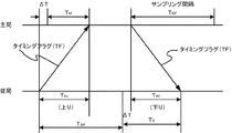
従来の保護リレー装置では、高精度なサンプリング同期制御を実現すべく、下記のようなデジタル電流差動リレーの構成が採用されている(非特許文献1参照)。このデジタル電流差動リレーは、図8の通り、主局と従局を有する2端子間において、自局のサンプリングタイミング時刻と相手端子からのサンプリングタイミングデータであるタイミングフラグ(TF)の受信時刻との時間間隔をそれぞれ測定し(TM及びTS)、この時間間隔TM及びTSからサンプリング同期誤差(ΔT)を算出している。 In a conventional protection relay device, the following configuration of a digital current differential relay is employed in order to realize highly accurate sampling synchronous control (see Non-Patent Document 1). This digital current differential relay, as shown in FIG. 8, between the sampling terminal time of its own station and the reception time of the timing flag (TF) which is the sampling timing data from the other terminal between the two terminals having the master station and the slave station. The time intervals are measured (T M and T S ), and the sampling synchronization error (ΔT) is calculated from the time intervals T M and T S.
つまり、このリレーでは、主局及び従局において、時間間隔TM又はTSを相手装置に伝達し、サンプリング同期誤差ΔTに基づきサンプリングタイミングを補正している。なお、このリレーにおける伝送フォーマットは、1フレームの長さが固定されており、かつ、サンプリング基準信号に対して固定の時間差で送信される。 That is, in this relay, the master station and the slave station transmit the time interval TM or TS to the counterpart device, and correct the sampling timing based on the sampling synchronization error ΔT. The transmission format in this relay has a fixed frame length and is transmitted with a fixed time difference with respect to the sampling reference signal.
なお、このサンプリング同期制御は、図8に示すように、対向端子間の上り、下りの伝送遅延時間が等しい、すなわち、従局から主局へのタイミングフラグTFの上りの伝送遅延時間Tduと、主局から従局へのタイミングフラグTFの下りの伝送遅延時間Tddと、が等しい必要がある。 In this sampling synchronization control, as shown in FIG. 8, the upstream and downstream transmission delay times between opposite terminals are equal, that is, the upstream transmission delay time T du of the timing flag TF from the slave station to the master station, The downstream transmission delay time T dd of the timing flag TF from the master station to the slave station needs to be equal.
また、高精度な時刻同期を実現するために、下記のような制限を加えるサンプリング制御方式も提案されている(特許文献1参照)。この方式では、伝送するフレームの長さを固定し、かつ、当該長さを一定値以下のものに制限し、さらには、同期フレームを優先的に中継させる優先送信機能を備えたスイッチングハブを採用している。
ところで、上記のような主局及び従局で時間間隔TM又はTSを相手装置に伝達し、サンプリング同期誤差ΔTに基づいてサンプリングタイミングを補正するサンプリング同期制御では、タイミングフラグTFの上りの伝送遅延時間Tduと下りの伝送遅延時間Tddが等しい必要があった。 By the way, in the sampling synchronization control in which the master station and the slave station transmit the time interval T M or T S to the partner apparatus and correct the sampling timing based on the sampling synchronization error ΔT, the transmission delay of the timing flag TF is increased. The time T du and the downstream transmission delay time T dd need to be equal.
しかしながら、イーサネット等のネットワークを使用した場合には、上りの伝送遅延時間Tduと下りの伝送遅延時間Tddを等しくすることが困難である。その理由として、ネットワーク中には一般的に複数台の中継装置が配設されており、この中継装置をフレームが通過する際には遅延が発生する点が挙がる。 However, when a network such as Ethernet is used, it is difficult to make the upstream transmission delay time T du equal to the downstream transmission delay time T dd . The reason is that a plurality of relay apparatuses are generally arranged in the network, and a delay occurs when a frame passes through the relay apparatuses.
また、この遅延時間はネットワークの負荷状態で変動し、さらに、当該遅延時間はネットワークの中継装置内部におけるフレーム処理の順番により変化する。そのため、ネットワーク内の中継装置をフレームが通過する伝送遅延時間を一定にすることができず、主局及び従局間の往復の伝送遅延時間は等しくならないので、高精度なサンプリング同期制御が実現できないでいた。 The delay time varies depending on the load state of the network, and further, the delay time changes depending on the order of frame processing in the network relay apparatus. For this reason, the transmission delay time for the frame to pass through the relay device in the network cannot be made constant, and the round-trip transmission delay time between the master station and the slave station is not equal, so high-precision sampling synchronization control cannot be realized. It was.
ここで、ネットワークを使用した場合の中継装置(イーサネットスイッチ)において、伝送遅延時間が一致しない点を図9を参照してより詳細に説明する。図9は、イーサネットスイッチ1に、クライアント3(1)〜クライアント3(n)及びサーバ4が接続された構成を示している。
Here, the point that the transmission delay times do not match in the relay apparatus (Ethernet switch) when the network is used will be described in more detail with reference to FIG. FIG. 9 shows a configuration in which the clients 3 (1) to 3 (n) and the server 4 are connected to the
図9のような構成では、イーサネットスイッチ1を介したクライアント3(1)及びクライアント3(2)のフレーム伝送遅延時間は次のように求められる。
まず、クライアント3(1)が、ケーブル31(1−1)上に宛先をサーバ4としたフレーム101を送信し、その直後に、クライアント3(2)がケーブル31(2−1)上に宛先をサーバ4としたフレーム102を送信する。この際のケーブル上におけるフレームの送信タイミングを示したタイムチャート1は、図10の通りである。
In the configuration as shown in FIG. 9, the frame transmission delay times of the clients 3 (1) and 3 (2) via the
First, the client 3 (1) transmits the
フレーム101とフレーム102はタイムチャート1で示す時間差Tdefでイーサネットスイッチ1に到着し、フレーム101は、このイーサネットスイッチ1からT101だけ遅延してケーブル31(2−n+1)上に出力される。一方、フレーム102は、フレーム101が出力中であるため、当該フレーム101の出力完了まで待機し、図10に示すように待ち時間T102後にイーサネットスイッチ1からケーブル31(2−n+1)上に出力される。
The
つまり、図10のタイムチャート1に示すように、フレーム101がイーサネットスイッチ1を通過する時間T101と、フレーム102がイーサネットスイッチ1を通過する時間T102は、同一ではない。このことから、フレームの伝送遅延時間を一定にすることは困難であり、ネットワークを使用した場合における2端子間の上りと下りの伝送遅延時間は一致しない。
That is, as shown in the
ここで、フレーム102のイーサネットスイッチ1の通過時間であるT102は、伝送速度とフレーム101のフレーム長で決まる。そのため、伝送速度が仮に100Mbpsでフレーム101のフレーム長が規格の最大長である12320ビットであった場合には、T102はおよそ123μsとなる。一方、フレーム101のイーサネットスイッチ1の通過時間であるT101は、イーサネットスイッチ1内のハードウエアの遅延時間で決まり、通常数百ns程度である。
Here, T102, which is the transit time of the
このように、イーサネットスイッチ1をフレームが通過する遅延時間は、T101の数百nsからT102の123μsまで変化するため、この遅延時間を固定することは困難である。
Thus, since the delay time for the frame to pass through the
また、特許文献1に記載されているような、フレーム長を固定し、かつ一定の長さ以下に制限し、さらに、同期フレームを優先的に中継する優先送信機能付きスイッチングハブを使用する方式では、伝送遅延時間のゆらぎを小さくしているが、フレーム長が一定値以下に制限されるので当該フレームの拡張性が犠牲となってしまう。さらに、フレーム長を一定値以下とする場合であっても、このフレーム長分の伝送遅延時間のゆらぎは生じてしまう。
Further, in a method using a switching hub with a priority transmission function that fixes a frame length and limits it to a certain length or less, and further relays a synchronization frame preferentially as described in
本発明は、上記課題を解消するために提案されたものであって、その目的は、同期フレームに対して常に伝送遅延時間を固定することが可能で、高精度なサンプリング同期制御が可能な通過時間固定装置を提供することにある。 The present invention has been proposed in order to solve the above-described problems, and its purpose is to always allow a transmission delay time to be fixed with respect to a synchronization frame, and to allow high-accuracy sampling synchronization control. It is to provide a time fixing device.
上述した目的を達成するために、本発明は、保護継電装置が各々設けられた各端子からの電流情報に基づいて当該各端子を繋ぐ送電線を保護するために、ネットワークを介して前記端子間のサンプリング同期を行い、当該端子間の伝送遅延時間を制御する通過時間固定装置であって、前記各端子からの電流情報を含む各種情報から構成されるフレームが相手端子との関係で同期フレームであるかを判定するフレーム種別判定手段と、前記フレーム種別判定手段により判定された同期フレームの相手端子への伝送を一定時間遅延させる一定時間遅延手段と、を備えることを特徴とする。 In order to achieve the above-described object, the present invention provides the terminal via a network in order to protect the power transmission line connecting the terminals based on current information from the terminals provided with the protective relay devices. Is a transit time fixing device that performs sampling synchronization between terminals and controls transmission delay time between the terminals, and a frame composed of various information including current information from each terminal is a synchronous frame in relation to the counterpart terminal Frame type determining means for determining whether the frame is determined, and constant time delay means for delaying transmission of the synchronization frame determined by the frame type determining means to the partner terminal for a predetermined time.
また、前記一定時間遅延手段は、前記保護継電器毎に各々設けられ、前記フレームは、対象とする前記一定時間遅延手段を特定するための宛先アドレス情報を含み、前記宛先アドレス情報に基づいて前記フレーム毎に前記一定時間遅延手段を特定する宛先特定手段を備えることを特徴とする点も本発明の一態様である。 The fixed time delay means is provided for each protection relay, and the frame includes destination address information for specifying the target fixed time delay means, and the frame is based on the destination address information. Another aspect of the present invention is that destination specifying means for specifying the fixed time delay means is provided for each time.
さらに、本発明は、前記一定時間遅延手段により遅延中である前記同期フレームが存在するかを判定する遅延フレーム判定手段と、前記遅延フレーム判定手段により遅延中の前記同期フレームが存在すると判定された場合に、前記フレーム種別判定手段により同期フレームでないと判定されたフレームを遅延させる遅延手段と、を備える点も包含する。 Further, in the present invention, a delay frame determination unit that determines whether or not the synchronization frame being delayed exists by the fixed time delay unit, and the delay frame determination unit determines that the delay of the synchronization frame exists. In this case, it also includes a delay unit that delays a frame that is determined not to be a synchronization frame by the frame type determination unit.
以上のような本発明によれば、同期フレームの往復の伝送遅延時間差をイーサネットスイッチで生じさせないので、高精度のサンプリング同期制御を実現することが可能となる。また、従来ではイーサネットスイッチにおける遅延時間ばらつきを最小限とするためにフレーム長を一定値以下に制限する必要が生じたが、本発明を適用することでフレーム長は制限されず、多くの情報量を効率よく伝送することが可能となる。 According to the present invention as described above, it is possible to realize highly accurate sampling synchronization control because the Ethernet switch does not cause a difference in the round trip transmission delay time of the synchronization frame. Conventionally, it has been necessary to limit the frame length to a certain value or less in order to minimize the delay time variation in the Ethernet switch. However, by applying the present invention, the frame length is not limited and a large amount of information is required. Can be transmitted efficiently.
[本実施形態]
[1.1.全体構成]
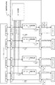
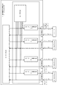
次に、本実施形態に係る構成について図1を参照して以下に説明する。
図1に示す通り、本実施形態の全体構成として、イーサネットスイッチ1と、クライアント3(1)〜クライアント3(n)及びサーバ4とが、本発明部分である通過時間固定装置2を介して繋がれている。ここで、クライアント3(1)〜クライアント3(n)及びサーバ4には、ネットワークインターフェイスハードウエアを備えた電流差動保護継電器装置等の一般的なものを採用している。
[This embodiment]
[1.1. overall structure]
Next, a configuration according to the present embodiment will be described below with reference to FIG.
As shown in FIG. 1, as an overall configuration of the present embodiment, an
イーサネットスイッチ1は、ネットワーク中の中継機器である汎用のスイッチングハブであり、通過時間固定装置2を介して、クライアント3(1)〜クライアント3(n)及びサーバ4から送られてきたデータを解析することで宛先を検出し、送り先のクライアント3(1)〜クライアント3(n)やサーバ4に送信する。
The Ethernet
また、このイーサネットスイッチ1は、クライアント3(1)〜クライアント3(n)及びサーバ4とインターフェイスするための複数個のポートを備え、当該ポートは図1のPHY41(1)〜PHY41(n+1)に対応する。つまり、イーサネットスイッチ1は、クライアント3(1)〜クライアント3(n)及びサーバ4から送信されたフレームの宛先アドレスに従って、当該フレームを所定のポートに送り出す機能を備えている。
The
[1.2.通過時間固定装置の構成]
次に、クライアント3(1)〜クライアント3(n)やサーバ4からのフレームの通過時間を固定する通過時間固定装置2の具体的な構成を詳述する。
図1の通り、通過時間固定装置2は、信号線27(1−1)〜(n+1)、(2−1)〜(2−n+1)を監視し、イーサネットスイッチ1、クライアント3(1)〜3(n)及びサーバ4から送信された同期フレームの検出を行う判定回路24を備えている。
[1.2. Configuration of the transit time fixing device]
Next, a specific configuration of the transit
As shown in FIG. 1, the transit
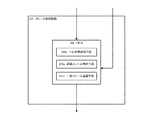
この判定回路24は、図2に示すように制御回路25を備え、当該制御回路25は、下記のような機能を有している。送られてきたフレームのフレーム種別を判定するフレーム種別判定手段25aと、そのフレームの宛先アドレスに基づいて送信対象とするフレーム制御回路23を特定し、当該フレームを特定先に出力する宛先判定手段25b(宛先特定手段に対応する。)と、を備えている。なお、このフレーム種別判定手段25aは、宛先アドレスにより同期フレームであると判定した場合には、遅延指令を宛先判定手段25bで特定されたフレーム制御回路23に送信し、同期フレーム以外と判定された場合には、この特定されたフレーム制御回路23に通過指令を送信する。 The determination circuit 24 includes a control circuit 25 as shown in FIG. 2, and the control circuit 25 has the following functions. Frame type determination means 25a for determining the frame type of the transmitted frame and frame control circuit 23 to be transmitted based on the destination address of the frame, and destination determination means 25b for outputting the frame to the specified destination (Corresponding to the destination specifying means). When the frame type determination unit 25a determines that the frame is a synchronization frame based on the destination address, the frame type determination unit 25a transmits a delay command to the frame control circuit 23 specified by the destination determination unit 25b, and determines that the frame is not a synchronization frame. In this case, a passage command is transmitted to the specified frame control circuit 23.
また、通過時間固定装置2は、判定回路24により検出された同期フレームを一定時間(固定時間)遅延した後にクライアント3(1)〜クライアント3(n)やサーバ4に送信するフレーム制御回路23(1)〜フレーム制御回路23(n+1)を備えている。なお、具体的なフレーム制御回路23の構成は[2.1.第1の動作例]の項目で詳述する。
In addition, the transit
また、図1に示すように、クライアント3(1)〜(n)及びサーバ4とインターフェイスするためのポートとしてPHY22(1)〜PHY22(n+1)と、イーサネットスイッチ1とインターフェイスするポートしてPHY21(1)〜PHY21(n+1)を備えている。
Further, as shown in FIG. 1, PHY 22 (1) to PHY 22 (n + 1) as ports for interfacing with the clients 3 (1) to (n) and the server 4, and ports for interfacing with the
[2.1.第1の動作例]
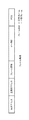
次に、上記のような構成を有する本実施形態に係る通過時間固定装置2の第1の動作例を以下に説明する。なお、フレーム101やフレーム102などのクライアント3から送信するフレーム構成1は、例えば、図11の通り、宛先アドレス、送信元アドレス、フレーム種別、データ部、FCS(チェックコード)から成る。
[2.1. First operation example]
Next, a first operation example of the transit
後述するが、このフレーム構成内のフレーム種別に基づいて、同期フレームとその他のフレーム(一般フレーム)とが区別され、同期フレームである場合に遅延時間を一定とする処理が施される。すなわち、通過時間固定装置2では、同期フレーム以外は当該固定装置2を通過するのみで遅延処理は行われない。
As will be described later, the synchronization frame and other frames (general frames) are distinguished from each other based on the frame type in the frame configuration, and processing for making the delay time constant is performed when the frame is the synchronization frame. That is, in the passage
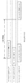
以下に、図3及び4を参照して、通過時間固定装置2の処理手順を時系列に従い示す。なお、ここでは、送信対象となるフレームが一般フレームを含まず、同期フレーム101の場合を説明する。
まず、図3に示すタイムチャート2のタイミングでクライアント3(1)からのフレーム101は、ポートであるPHY22(1)を通じて通過時間固定装置2に送信される。
Below, with reference to FIG. 3 and 4, the process sequence of the passage
First, the
そして、通過時間固定装置2内に設けられた判定回路24において、制御回路25中のフレーム種別判定手段25aが、クライアント3(1)から送られたフレーム101のフレーム種別を判定する。ここで、フレーム種別判定手段25aによりクライアント3(1)からのフレーム101が同期フレームであると判断されると、フレーム制御回路23(n+1)に対して、当該フレーム101の一定時間の遅延指令を下す。
Then, in the determination circuit 24 provided in the passage
なお、制御回路25中の宛先判定手段25bは、受信したフレーム101から宛先アドレスを取得することで、遅延指令の対象となるフレーム制御回路23(n+1)を特定する。具体的には、同期フレーム101の宛先として、フレーム制御回路23(n+1)とPHY23(2−n+1)が設定されているので、宛先判定手段25bは、遅延指令を送る対象としてフレーム制御回路23(n+1)を特定し、当該フレーム制御回路23(n+1)に対して遅延指令を下す。
The destination determination unit 25b in the control circuit 25 acquires the destination address from the received
ここで、フレーム制御回路23は、図4に示すように、FIFO26を備え、遅延指令が下された場合に、この遅延が必要な同期フレームをFIFO26で一定時間蓄積することで遅延時間を経過させる。より詳細には、このFIFO26内に同期フレームを一定時間遅延させる一定時間遅延手段26aを備え、この一定時間遅延手段26aが、当該同期フレームを一定時間遅延させる。
Here, as shown in FIG. 4, the frame control circuit 23 includes a
一方、遅延処理を行わないフレームの場合は、判定回路24中の制御回路25がFIFO26に対してフレームの通過指令を下し、一定時間の遅延をさせることなく、フレーム制御回路23を通過させる。すなわち、制御回路25中のフレーム種別判定手段25aにより同期フレームでないと判定された場合には、フレームの通過指令が下されるので、一定時間遅延手段26aによる遅延処理は行われず、当該フレームはフレーム制御回路23を通過する。
On the other hand, in the case of a frame for which delay processing is not performed, the control circuit 25 in the determination circuit 24 issues a frame passage command to the
このことから、図3の通り、フレーム制御回路23(1)〜(n+1)では、受信した当該同期フレーム101を一定時間遅延手段26aにより一定時間遅延させ、遅延が完了すると、宛先アドレスに基づく特定された当該フレーム制御回路23(n+1)に対応するPHY22(n+1)を通じて、この同期フレーム101をケーブル31(2−n+1)上に出力する。つまり、フレーム制御回路23(n+1)で同期フレーム101を一定時間遅延させることができるので、伝送遅延時間を固定することが可能である。
Therefore, as shown in FIG. 3, in the frame control circuits 23 (1) to (n + 1), the received
なお、FIFO26で遅延させる同期フレームの一定時間、すなわち、一定時間遅延手段26aにより遅延される一定時間は、フレームの伝送に使用するポートの伝送速度により相違し、下記のように表すことができる。
The fixed time of the synchronization frame delayed by the
[数1]
(規格上の最大フレーム長+α)*伝送時間
但し、この遅延時間として最大遅延時間を固定しても構わない。
[Equation 1]
(Standard maximum frame length + α) * Transmission time However, the maximum delay time may be fixed as this delay time.
例えば、フレーム長が8000バイト(規格上の最大フレーム長+α)で伝送速度が1[数2]
Gbpsの場合の遅延時間は次の通りである。
(8000バイト * 8ビット)/1G = 64μs
For example, the frame length is 8000 bytes (standard maximum frame length + α) and the transmission speed is 1 [Expression 2]
The delay time in the case of Gbps is as follows.
(8000 bytes * 8 bits) / 1G = 64μs
[2.2.第2の動作例]
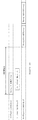
次に、上記構成を有する通過時間固定装置2の第2の動作例を図5に示すタイムチャート3を参照して以下に説明する。なお、第2の動作例では、クライアント3(2)からの一般フレーム102、クライアント3(1)からの同期フレーム101の順にフレームが通過時間固定装置2に送信される場合の動作手順について説明する。
[2.2. Second operation example]
Next, a second operation example of the transit
まず、図5のタイムチャート3によれば、クライアント3(2)からのフレーム102がPHY22(2)を通じて通過時間固定装置2に送信される。そして、判定回路24内の制御回路25が、このクライアント2から送信されたフレーム102のフレーム種別を判定する。すなわち、制御回路25内のフレーム種別判定手段25aが受信したフレーム102が同期フレームであるか、それ以外であるかを判定する。
First, according to the time chart 3 of FIG. 5, the
上述した通り、このフレーム102は一般フレームであるので、フレーム種別判定手段25aは同期フレームでないと判定する。また、宛先判定手段25bはフレーム102の宛先アドレスに基づいて送信対象であるフレーム制御回路23(n+1)を特定する。ここで、フレーム種別判定手段25aにより同期フレーム以外のフレーム、すなわち一般フレームと判定されているので、当該フレーム種別判定手段25aは、宛先判定手段25bにより特定されたフレーム制御回路23(n+1)に対して遅延指令を下さず、当該フレーム102の通過指令を送る。
As described above, since the
これにより、この一般フレーム102は、宛先判定手段25bにより特定されたフレーム制御回路23(n+1)を通過し、ケーブル31(2−n+1)上に出力される。つまり、この一般フレーム102は、FIFO26内の一定時間遅延手段26aにより遅延処理が施されることなく、当該FIFO26を通過し、ケーブル31(2−n+1)上に出力される。
As a result, the
そして、図5のタイムチャート3の通り、クライアント3(1)からのフレーム101がPHY22(1)を通じて通過時間固定装置2に送信される。通過時間固定装置2内の判定回路24では、制御回路25中のフレーム種別判定手段25aによりクライアント3(1)から送信されたこのフレーム101のフレーム種別が判定される。
Then, as shown in the time chart 3 of FIG. 5, the
上述した通り、クライアント3(1)からフレーム101は同期フレームであるため、このフレーム種別判定手段25aは、当該フレーム101を同期フレーム101と判定する。また、制御回路25内の宛先判定手段25bは、この同期フレーム101の宛先アドレスに基づいて送信対象となるフレーム制御回路23(n+1)を特定する。なお、フレーム種別判定手段25aは、同期フレーム101と判定すると、宛先判定手段25bにより特定されたフレーム制御回路23(n+1)に当該フレーム101の遅延指令を送信する。
As described above, since the
遅延指令が下されたフレーム制御回路23(n+1)では、FIFO26内の一定時間遅延手段26aが、この同期フレーム101をタイムチャート3に示すように一定時間遅延させ、遅延が完了した同期フレーム101をケーブル31(2−n+1)上に出力する。すなわち、一定時間遅延手段26aにより同期フレーム101がFIFO26内に一定時間蓄積され、この一定時間が経過するとケーブル31(2−n+1)上に出力される。
In the frame control circuit 23 (n + 1) for which the delay command has been issued, the fixed time delay means 26a in the
[2.3.第3の動作例]
次に、通過時間固定装置2の第3の動作例について図6のタイムチャート4を参照して以下に説明する。なお、第3の動作例では、クライアント3(1)からの同期フレーム101、クライアント3(2)からの一般フレーム102の順に通過時間固定装置2に送信する場合の動作手順について説明する。
[2.3. Third operation example]
Next, a third operation example of the passage
また、第3の動作例では、フレーム制御回路23内に当該フレーム制御回路23に遅延中のフレームが存在するかを判定する遅延フレーム判定手段26bを備えている。さらに、遅延フレーム判定手段26bにより遅延中のフレームが存在すると判定された場合に、同期フレーム以外のフレームを当該遅延中のフレームの遅延が完了するまで待機させる一般フレーム待機手段26c(遅延手段に対応する。)も備えている。 In the third operation example, the frame control circuit 23 includes a delay frame determination unit 26b that determines whether or not there is a delayed frame in the frame control circuit 23. Further, when the delay frame determination unit 26b determines that there is a delayed frame, the general frame standby unit 26c (corresponding to the delay unit) waits for a frame other than the synchronization frame until the delay of the delayed frame is completed. Yes).
まず、図6のタイムチャート4に示すように、クライアント3(1)からのフレーム101がPHY22(1)を通じて通過時間固定装置2に送信される。通過時間固定装置2に送信されると、判定回路24内の制御回路25が、クライアント3(1)からのフレーム101のフレーム種別を判定する。すなわち、制御回路25内のフレーム種別判定手段25aが、クライアント3(1)からのフレーム101が同期フレームか、それ以外かを判定する。
First, as shown in the time chart 4 of FIG. 6, the
また、制御回路25内の宛先判定手段25bは、このフレーム101の宛先アドレスから送信対象となるフレーム制御回路23(n+1)を特定する。そして、フレーム種別判定手段25aは、この宛先判定手段25bにより特定されたフレーム制御回路23(n+1)に対してフレーム101の遅延指令を下す。
The destination determination unit 25b in the control circuit 25 identifies the frame control circuit 23 (n + 1) to be transmitted from the destination address of the
次に、図6のタイムチャート4の通り、クライアント2(313)からのフレーム102がPHY22(2)を通じて通過時間固定装置2に送信される。通過時間固定装置2にクライアント3(2)からのフレーム102が送信されると、判定回路24の制御回路25内のフレーム種別判定手段25aが当該フレーム102のフレーム種別を判定する。
Next, as shown in the time chart 4 of FIG. 6, the
ここでは、上述した通り、クライアント3(2)からのフレーム102は一般フレームであるため、フレーム種別判定手段25aは、同期フレーム以外のフレーム、すなわち一般フレーム102と判定する。また、制御回路25内の宛先判定手段25bは、このフレーム102の宛先アドレスに基づいて送信対象となるフレーム制御回路23(n+1)を特定する。フレーム種別判定手段25aは、この宛先判定手段25bにより特定されたフレーム制御回路23(n+1)に対して、フレーム102の通過指令を送る。
Here, as described above, since the
ここで、宛先判定手段25bにより特定されたフレーム制御回路23(n+1)にクライアント3(2)からの一般フレーム102が送られると、当該フレーム制御回路23(n+1)の遅延フレーム判定手段26bは、FIFO26に遅延中のフレームが存在するかを判定する。図6のタイムチャート4に示すように、本動作例では、先のクライアント3(1)から送信された同期フレーム101が一定時間の遅延中であるため、遅延フレーム判定手段26bにより遅延中のフレーム101が存在すると判定される。
Here, when the
このフレーム制御回路23(n+1)では、先の同期フレーム101が遅延中であるので、一般フレーム待機手段26cは、図6の通り、クライアント2からの一般フレーム102を同期フレームの一定時間の遅延が完了するまで遅延させる。つまり、フレーム制御回路23(n+1)に送信された一般フレーム102は、FIFO26に先の同期フレーム101の遅延が終了するまでの間蓄積される。
In this frame control circuit 23 (n + 1), since the
そして、クライアント3(1)からの同期フレーム101の一定時間の遅延が完了し、PHY22(n+1)を通じてケーブル31(2−n+1)上に出力されると、一般フレーム待機手段70cによる一般フレーム102の待機も終了し、当該フレーム102は同期フレーム101に続きケーブル31(2−n+1)上に出力される。
Then, when the delay of the predetermined time of the
以上のような本実施形態によれば、フレーム制御回路で同期フレームを一定時間遅延させることができるので、同期フレームに対して常に伝送遅延時間を固定することが可能となる。さらに、同期フレームの往復の伝送遅延時間差をイーサネットスイッチで生じさせないので、高精度のサンプリング同期制御を実現することができる。また、フレーム長を一定値以下に制限する必要はないので、多くの情報量を効率よく伝送することが可能となる。 According to the present embodiment as described above, since the synchronization frame can be delayed for a certain time by the frame control circuit, the transmission delay time can always be fixed with respect to the synchronization frame. Furthermore, since the difference in transmission delay time between the synchronization frames is not generated by the Ethernet switch, highly accurate sampling synchronization control can be realized. In addition, since it is not necessary to limit the frame length to a certain value or less, a large amount of information can be transmitted efficiently.
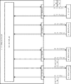
[他の実施形態]
なお、本発明は、上記のような実施形態に限定されるものではなく、下記のような実施形態も包含する。すなわち、図7に示す通り、上記で示したような通過時間固定装置2の判定回路24及びフレーム制御回路23の構成をイーサネットスイッチ1内に採用する実施形態も本発明は包含する。これにより、イーサネットスイッチ1単独で高精度なサンプリング時刻の同期制御が可能となる。
[Other Embodiments]
In addition, this invention is not limited to the above embodiments, The following embodiment is also included. That is, as shown in FIG. 7, the present invention also includes an embodiment in which the configuration of the determination circuit 24 and the frame control circuit 23 of the transit
1…イーサネットスイッチ
2…通過時間固定装置
3…クライアント
4…サーバ
21…PHY(1)〜(n+1)
22…PHY(1)〜(n+1)
23…フレーム制御回路
24…判定回路
25…制御回路
25a…フレーム種別判定手段
25b…宛先判定手段
26…FIFO
26a…一定時間遅延手段
26b…遅延フレーム判定手段
26c…一般フレーム待機手段
27…信号線(1−1)〜(n+1)、(2−1)〜(2−n+1)
31…ケーブル(1−1)〜(1−n)、(2−1)〜(2−n+1)
41…PHY(1)〜(n+1)
70c…一般フレーム待機手段
101…フレーム(同期フレーム)
102…フレーム(一般フレーム)
DESCRIPTION OF
22 ... PHY (1) to (n + 1)
23 ... Frame control circuit 24 ... Determination circuit 25 ... Control circuit 25a ... Frame type determination means 25b ... Destination determination means 26 ... FIFO
26a ... definite time delay means 26b ... delay frame determination means 26c ... general frame standby means 27 ... signal lines (1-1) to (n + 1), (2-1) to (2-n + 1)
31 ... Cables (1-1) to (1-n), (2-1) to (2-n + 1)
41 ... PHY (1) to (n + 1)
70c: General frame waiting means 101: Frame (synchronous frame)
102 ... Frame (general frame)
Claims (5)
前記各端子からの電流情報を含む各種情報から構成されるフレームが相手端子との関係で同期フレームであるかを判定するフレーム種別判定手段と、
前記フレーム種別判定手段により判定された同期フレームの相手端子への伝送を一定時間遅延させる一定時間遅延手段と、
を備えることを特徴とする通過時間固定装置。 In order to protect the power transmission line connecting the terminals based on the current information from the terminals provided with the protective relay devices, sampling synchronization between the terminals is performed via a network, and the transmission delay between the terminals is performed. A transit time fixing device for controlling time,
Frame type determination means for determining whether a frame composed of various information including current information from each terminal is a synchronous frame in relation to the counterpart terminal;
Fixed time delay means for delaying transmission of the synchronization frame determined by the frame type determination means to the counterpart terminal for a fixed time;
A transit time fixing device comprising:
前記宛先アドレス情報に基づいて前記フレーム毎に前記一定時間遅延手段を特定する宛先特定手段を備えることを特徴とする請求項1又は2に記載の通過時間固定装置。 The frame includes destination address information for specifying the target fixed time delay means,
3. The transit time fixing apparatus according to claim 1, further comprising destination specifying means for specifying the fixed time delay means for each frame based on the destination address information.
前記遅延フレーム判定手段により遅延中の前記同期フレームが存在すると判定された場合に、前記フレーム種別判定手段により同期フレームでないと判定されたフレームを遅延させる遅延手段と、
を備えることを特徴とする請求項1〜3のいずれか1項に記載の通過時間固定装置。 Delay frame determining means for determining whether or not there is the synchronization frame being delayed by the fixed time delay means;
A delay unit that delays a frame that is determined not to be a synchronization frame by the frame type determination unit when the delay frame determination unit determines that the synchronization frame being delayed exists;
The transit time fixing device according to any one of claims 1 to 3, further comprising:
Priority Applications (5)
| Application Number | Priority Date | Filing Date | Title |
|---|---|---|---|
| JP2008220315A JP5249682B2 (en) | 2008-08-28 | 2008-08-28 | Passage time fixing device for protective relay device |
| CN200980133725.5A CN102138302B (en) | 2008-08-28 | 2009-08-28 | Elapsed time fixing device |
| US13/061,346 US8599883B2 (en) | 2008-08-28 | 2009-08-28 | Transit time fixation device |
| EP09809610.0A EP2320602B1 (en) | 2008-08-28 | 2009-08-28 | Transit time fixation device |
| PCT/JP2009/004243 WO2010023955A1 (en) | 2008-08-28 | 2009-08-28 | Elapsed time fixing device |
Applications Claiming Priority (1)
| Application Number | Priority Date | Filing Date | Title |
|---|---|---|---|
| JP2008220315A JP5249682B2 (en) | 2008-08-28 | 2008-08-28 | Passage time fixing device for protective relay device |
Related Child Applications (1)
| Application Number | Title | Priority Date | Filing Date |
|---|---|---|---|
| JP2013083028A Division JP2013141319A (en) | 2013-04-11 | 2013-04-11 | Protection relay system and transit time fixing method of protection relay system |
Publications (2)
| Publication Number | Publication Date |
|---|---|
| JP2010056947A true JP2010056947A (en) | 2010-03-11 |
| JP5249682B2 JP5249682B2 (en) | 2013-07-31 |
Family
ID=41721136
Family Applications (1)
| Application Number | Title | Priority Date | Filing Date |
|---|---|---|---|
| JP2008220315A Expired - Fee Related JP5249682B2 (en) | 2008-08-28 | 2008-08-28 | Passage time fixing device for protective relay device |
Country Status (5)
| Country | Link |
|---|---|
| US (1) | US8599883B2 (en) |
| EP (1) | EP2320602B1 (en) |
| JP (1) | JP5249682B2 (en) |
| CN (1) | CN102138302B (en) |
| WO (1) | WO2010023955A1 (en) |
Cited By (5)
| Publication number | Priority date | Publication date | Assignee | Title |
|---|---|---|---|---|
| JP2013074340A (en) * | 2011-09-26 | 2013-04-22 | Fujitsu Ltd | Repeating device and repeating method |
| JP2013162254A (en) * | 2012-02-03 | 2013-08-19 | Nec Corp | Relay device, relay device control method, and relay device control program |
| WO2014083628A1 (en) * | 2012-11-28 | 2014-06-05 | 三菱電機株式会社 | Relay device, communication system and relay method |
| WO2014112264A1 (en) | 2013-01-15 | 2014-07-24 | 株式会社 東芝 | Protective relay system and protective relay device |
| JP2020155942A (en) * | 2019-03-20 | 2020-09-24 | 三菱電機株式会社 | Protection control device |
Families Citing this family (7)
| Publication number | Priority date | Publication date | Assignee | Title |
|---|---|---|---|---|
| JP5475551B2 (en) * | 2010-05-28 | 2014-04-16 | 株式会社東芝 | Protective relay device |
| US20150318939A1 (en) * | 2013-02-27 | 2015-11-05 | Mitsubishi Electric Corporation | Relay device, relay method, and relay program |
| WO2016132539A1 (en) * | 2015-02-20 | 2016-08-25 | 三菱電機株式会社 | Communication apparatus, communication system and communication method |
| US10033517B2 (en) * | 2015-03-19 | 2018-07-24 | Mitsubishi Electric Corporation | Communication apparatus and network system |
| CN105119376B (en) * | 2015-09-09 | 2017-08-22 | 许继集团有限公司 | A kind of sampling implementation method and device based on routine sampling GOOSE tripped modes |
| CN105958469B (en) * | 2016-06-15 | 2018-08-24 | 厦门科灿信息技术有限公司 | A kind of programmable multi-machine parallel connection power-supply system is synchronous and current equalizing method |
| JP7103788B2 (en) * | 2017-12-28 | 2022-07-20 | トヨタ自動車株式会社 | In-vehicle systems, gateways, programs, information processing methods, information processing systems, and vehicles |
Citations (4)
| Publication number | Priority date | Publication date | Assignee | Title |
|---|---|---|---|---|
| JPH10262075A (en) * | 1997-03-18 | 1998-09-29 | Fujitsu Ltd | Switching hub |
| JP2000332809A (en) * | 1999-05-24 | 2000-11-30 | Mitsubishi Electric Corp | Optical field network system |
| JP2000358069A (en) * | 1999-06-15 | 2000-12-26 | Mitsubishi Electric Corp | Communication network, and slave connecting device, master connecting device, multiplexing device, and repeating device constituting communication network |
| JP2001177570A (en) * | 1999-12-17 | 2001-06-29 | Mitsubishi Electric Corp | Communication network system, and slave unit, master unit, repeater and synchronization controlling method in communication network system |
Family Cites Families (10)
| Publication number | Priority date | Publication date | Assignee | Title |
|---|---|---|---|---|
| JPS6039310A (en) | 1983-08-12 | 1985-03-01 | 株式会社東芝 | Sampling synchronizing method |
| JP2001156857A (en) * | 1999-11-25 | 2001-06-08 | Fujikura Ltd | Converter for lan |
| US6954432B1 (en) * | 2000-10-04 | 2005-10-11 | Motorola, Inc. | Method and apparatus for improving perceived signal quality of transmitted information in a full duplex wireless communication system |
| US20030112758A1 (en) * | 2001-12-03 | 2003-06-19 | Pang Jon Laurent | Methods and systems for managing variable delays in packet transmission |
| US7126800B2 (en) * | 2003-07-11 | 2006-10-24 | General Electric Company | Method and system for communications channel delay asymmetry compensation using global positioning systems |
| US7991296B1 (en) * | 2006-11-10 | 2011-08-02 | Marvell International Ltd. | Method and apparatus for data frame synchronization and delineation |
| JP2008125251A (en) * | 2006-11-13 | 2008-05-29 | Mitsubishi Electric Corp | Relay system and pcm current differential relay system in electric power station |
| US8208815B1 (en) * | 2006-11-30 | 2012-06-26 | Marvell International Ltd. | Bit accurate upstream burst transmission phase method for reducing burst data arrival variation |
| US7818389B1 (en) * | 2006-12-01 | 2010-10-19 | Marvell International Ltd. | Packet buffer apparatus and method |
| US20080309505A1 (en) * | 2007-06-18 | 2008-12-18 | Mitsubishi Electric Corporation | Current-differential relay device |
-
2008
- 2008-08-28 JP JP2008220315A patent/JP5249682B2/en not_active Expired - Fee Related
-
2009
- 2009-08-28 US US13/061,346 patent/US8599883B2/en not_active Expired - Fee Related
- 2009-08-28 EP EP09809610.0A patent/EP2320602B1/en not_active Not-in-force
- 2009-08-28 CN CN200980133725.5A patent/CN102138302B/en not_active Expired - Fee Related
- 2009-08-28 WO PCT/JP2009/004243 patent/WO2010023955A1/en active Application Filing
Patent Citations (4)
| Publication number | Priority date | Publication date | Assignee | Title |
|---|---|---|---|---|
| JPH10262075A (en) * | 1997-03-18 | 1998-09-29 | Fujitsu Ltd | Switching hub |
| JP2000332809A (en) * | 1999-05-24 | 2000-11-30 | Mitsubishi Electric Corp | Optical field network system |
| JP2000358069A (en) * | 1999-06-15 | 2000-12-26 | Mitsubishi Electric Corp | Communication network, and slave connecting device, master connecting device, multiplexing device, and repeating device constituting communication network |
| JP2001177570A (en) * | 1999-12-17 | 2001-06-29 | Mitsubishi Electric Corp | Communication network system, and slave unit, master unit, repeater and synchronization controlling method in communication network system |
Cited By (12)
| Publication number | Priority date | Publication date | Assignee | Title |
|---|---|---|---|---|
| JP2013074340A (en) * | 2011-09-26 | 2013-04-22 | Fujitsu Ltd | Repeating device and repeating method |
| US9204408B2 (en) | 2011-09-26 | 2015-12-01 | Fujitsu Limited | Relaying apparatus and relaying method |
| JP2013162254A (en) * | 2012-02-03 | 2013-08-19 | Nec Corp | Relay device, relay device control method, and relay device control program |
| WO2014083628A1 (en) * | 2012-11-28 | 2014-06-05 | 三菱電機株式会社 | Relay device, communication system and relay method |
| JP5791828B2 (en) * | 2012-11-28 | 2015-10-07 | 三菱電機株式会社 | Relay device, communication system, and relay method |
| US9497018B2 (en) | 2012-11-28 | 2016-11-15 | Mitsubishi Electric Corporation | Relay device, communication system and relay method |
| WO2014112264A1 (en) | 2013-01-15 | 2014-07-24 | 株式会社 東芝 | Protective relay system and protective relay device |
| JP2014138454A (en) * | 2013-01-15 | 2014-07-28 | Toshiba Corp | Protection relay system and protection relay device |
| JP2017104013A (en) * | 2013-01-15 | 2017-06-08 | 株式会社東芝 | Protection relay system |
| US9871365B2 (en) | 2013-01-15 | 2018-01-16 | Kabushiki Kaisha Toshiba | Protective relay system and protective relay device |
| JP2020155942A (en) * | 2019-03-20 | 2020-09-24 | 三菱電機株式会社 | Protection control device |
| JP7097840B2 (en) | 2019-03-20 | 2022-07-08 | 三菱電機株式会社 | Protection control device |
Also Published As
| Publication number | Publication date |
|---|---|
| WO2010023955A1 (en) | 2010-03-04 |
| EP2320602A4 (en) | 2013-10-23 |
| US8599883B2 (en) | 2013-12-03 |
| EP2320602A1 (en) | 2011-05-11 |
| JP5249682B2 (en) | 2013-07-31 |
| US20110158263A1 (en) | 2011-06-30 |
| EP2320602B1 (en) | 2014-11-19 |
| CN102138302A (en) | 2011-07-27 |
| CN102138302B (en) | 2013-10-09 |
Similar Documents
| Publication | Publication Date | Title |
|---|---|---|
| JP5249682B2 (en) | Passage time fixing device for protective relay device | |
| US8081663B2 (en) | Time synchronization method and relay apparatus | |
| JP5377663B2 (en) | COMMUNICATION SYSTEM, COMMUNICATION DEVICE, AND TIME SYNCHRONIZATION METHOD | |
| US9537648B2 (en) | Data transmission over packet switched network | |
| US10149025B2 (en) | Optical packet sending method and device, optical packet processing method, and optical switching device | |
| JP2014233008A (en) | Industrial device, controller, data transfer method, and data transmission method | |
| KR20110081910A (en) | Link band estimating apparatus | |
| JP5798807B2 (en) | Optical communication apparatus and signal adjustment method | |
| JP4815534B2 (en) | Packet delay characteristic measuring apparatus and method | |
| KR101417459B1 (en) | An improved data processing method and system on gateway used in real-time communication within vehicle components | |
| KR20140069649A (en) | Guard time control method through propagation delay estimation and time synchronization acquisition | |
| JP2013141319A (en) | Protection relay system and transit time fixing method of protection relay system | |
| JP2019176289A (en) | Radio communication device, radio communications system, and radio communication method | |
| JP6192847B1 (en) | COMMUNICATION SYSTEM, COMMUNICATION DEVICE, AND COMMUNICATION METHOD | |
| EP3729752A1 (en) | Data communication | |
| Ma et al. | Demonstration of latency control label-based bounded-jitter scheduling in a bridged network for industrial internet | |
| KR101708398B1 (en) | Synchronization method for terminal on profiled network and networking apparatus performing the same | |
| WO2016129281A1 (en) | Packet train transmitting/receiving device, network state estimation system and control method | |
| US20180234315A1 (en) | Data division unit, communication device, communication system, data division method, and storage medium having data division program stored therein | |
| JP5969424B2 (en) | Communications system | |
| JP2012114712A (en) | Communication device and communication system | |
| JP2002344515A (en) | Data relay method and device thereof |
Legal Events
| Date | Code | Title | Description |
|---|---|---|---|
| A621 | Written request for application examination |
Free format text: JAPANESE INTERMEDIATE CODE: A621 Effective date: 20110525 |
|
| A131 | Notification of reasons for refusal |
Free format text: JAPANESE INTERMEDIATE CODE: A131 Effective date: 20121030 |
|
| A521 | Request for written amendment filed |
Free format text: JAPANESE INTERMEDIATE CODE: A523 Effective date: 20121228 |
|
| TRDD | Decision of grant or rejection written | ||
| A01 | Written decision to grant a patent or to grant a registration (utility model) |
Free format text: JAPANESE INTERMEDIATE CODE: A01 Effective date: 20130319 |
|
| A61 | First payment of annual fees (during grant procedure) |
Free format text: JAPANESE INTERMEDIATE CODE: A61 Effective date: 20130412 |
|
| FPAY | Renewal fee payment (event date is renewal date of database) |
Free format text: PAYMENT UNTIL: 20160419 Year of fee payment: 3 |
|
| LAPS | Cancellation because of no payment of annual fees |