JP2010041777A - 圧電振動子の保持装置 - Google Patents
圧電振動子の保持装置 Download PDFInfo
- Publication number
- JP2010041777A JP2010041777A JP2008199643A JP2008199643A JP2010041777A JP 2010041777 A JP2010041777 A JP 2010041777A JP 2008199643 A JP2008199643 A JP 2008199643A JP 2008199643 A JP2008199643 A JP 2008199643A JP 2010041777 A JP2010041777 A JP 2010041777A
- Authority
- JP
- Japan
- Prior art keywords
- piezoelectric vibrator
- leaf spring
- holding device
- fixed
- support member
- Prior art date
- Legal status (The legal status is an assumption and is not a legal conclusion. Google has not performed a legal analysis and makes no representation as to the accuracy of the status listed.)
- Granted
Links
- 238000006073 displacement reaction Methods 0.000 claims description 9
- 238000012423 maintenance Methods 0.000 claims description 6
- 230000013011 mating Effects 0.000 description 14
- 230000004048 modification Effects 0.000 description 6
- 238000012986 modification Methods 0.000 description 6
- 238000005452 bending Methods 0.000 description 3
- 230000008602 contraction Effects 0.000 description 2
- 230000000694 effects Effects 0.000 description 2
- 230000005483 Hooke's law Effects 0.000 description 1
- 238000006243 chemical reaction Methods 0.000 description 1
Images


Classifications
-
- H—ELECTRICITY
- H02—GENERATION; CONVERSION OR DISTRIBUTION OF ELECTRIC POWER
- H02N—ELECTRIC MACHINES NOT OTHERWISE PROVIDED FOR
- H02N2/00—Electric machines in general using piezoelectric effect, electrostriction or magnetostriction
- H02N2/0005—Electric machines in general using piezoelectric effect, electrostriction or magnetostriction producing non-specific motion; Details common to machines covered by H02N2/02 - H02N2/16
- H02N2/001—Driving devices, e.g. vibrators
- H02N2/003—Driving devices, e.g. vibrators using longitudinal or radial modes combined with bending modes
- H02N2/004—Rectangular vibrators
-
- H—ELECTRICITY
- H02—GENERATION; CONVERSION OR DISTRIBUTION OF ELECTRIC POWER
- H02N—ELECTRIC MACHINES NOT OTHERWISE PROVIDED FOR
- H02N2/00—Electric machines in general using piezoelectric effect, electrostriction or magnetostriction
- H02N2/0005—Electric machines in general using piezoelectric effect, electrostriction or magnetostriction producing non-specific motion; Details common to machines covered by H02N2/02 - H02N2/16
- H02N2/005—Mechanical details, e.g. housings
- H02N2/0055—Supports for driving or driven bodies; Means for pressing driving body against driven body
- H02N2/006—Elastic elements, e.g. springs
-
- H—ELECTRICITY
- H10—SEMICONDUCTOR DEVICES; ELECTRIC SOLID-STATE DEVICES NOT OTHERWISE PROVIDED FOR
- H10N—ELECTRIC SOLID-STATE DEVICES NOT OTHERWISE PROVIDED FOR
- H10N30/00—Piezoelectric or electrostrictive devices
- H10N30/20—Piezoelectric or electrostrictive devices with electrical input and mechanical output, e.g. functioning as actuators or vibrators
- H10N30/202—Piezoelectric or electrostrictive devices with electrical input and mechanical output, e.g. functioning as actuators or vibrators using longitudinal or thickness displacement combined with bending, shear or torsion displacement
- H10N30/2023—Piezoelectric or electrostrictive devices with electrical input and mechanical output, e.g. functioning as actuators or vibrators using longitudinal or thickness displacement combined with bending, shear or torsion displacement having polygonal or rectangular shape
Landscapes
- General Electrical Machinery Utilizing Piezoelectricity, Electrostriction Or Magnetostriction (AREA)
Abstract
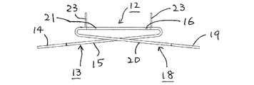
【解決手段】圧電振動子の保持装置において、圧電振動子1を離隔して収容する枠形または箱形の支持部材11と、この支持部材11の側部と圧電振動子1との間に介在される板ばね構造体12とを有し、この板ばね構造体12は、支持部材11の片側部に固着された基端部から圧電振動子1の対向両側部を挟むように圧電振動子の側部をまたいで折り返されて該圧電振動子に固着された第1の板ばね部材13と、支持部材11の他方の片側部に固着された基端部から圧電振動子1の対向両側部を挟むように圧電振動子1の側部をまたいで折り返されて該圧電振動子に固着された第2の板ばね部材18とを有し、第1の板ばね部材13と第2の板ばね部材18が圧電振動子1との固着部分で一体化されている。
【選択図】 図7
Description
本発明はさらに、圧電振動子に一定の加圧力を付与することができ、より、低コストでコンパクトな構造を有し、かつ、安定した出力を維持できる圧電振動子の保持装置を提供することにある。
また、本発明に係る圧電振動子は全体として棒状の形状を成し、かつその横断面が矩形状あるいは多角形状のもの、および横断面が円形状あるいは楕円形状のもの等いずれの形状のものにも適用可能である。
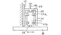
図2は第1実施形態の変形例1を示す側部断面図である。この例では、角柱状圧電振動子1の対向両側面にそれぞれ一対の平行な板ばね5,8が固着され、かつ、その固着位置は圧電振動子1の節部6(図3)の位置となっている。各々の板ばね5,8の圧電振動子1と反対側の板ばね端部5b,8bは支持部材3に接着固定される。4枚の板ばね5,8はともにその板面5a,8aが圧電振動子の加圧方向に向いており、また、これら4枚の板ばね5,8は互いに平行に配置されている。動作開始時に圧電振動子1の出力面1aの突部2を相手部材に圧接させるときは、図1(c)で説明した場合と同様に圧電振動子1が相手部材によって加圧方向と反対側へ若干押し込まれるように初期位置の設定がなされ、この位置で圧電振動子1の突部2と相手部材間に板ばね5,8のばね力による初期加圧力がかけられる。
上述の第2実施形態では、圧電振動子の1つの対向両側面に板ばねを固着した例を示したが、第2実施形態の変形例として圧電振動子の2つの対向両側面、即ち、4側面に同様の押し付け設定時に座屈状態となる板ばねを取り付けた構造とすることもできる。そして非線形ばね特性の荷重一定部分を利用することにより、被移動体や被加工物となる相手部材と圧電振動子との距離(振動子の加圧方向の接触位置)が或る領域で変化しても、加圧力を一定で作用させることができる。したがって、本発明の超音波モータや超音波加工機においては、相手部材に安定した摩擦力や加工力の作用を与えることができる。
第1の板ばね部材13は、支持部材11の一方の側壁11bに固着される幅広の基端部14を有する。この基端部14から圧電振動子1の対向両側部1dを挟むように一対の帯状部15が該側部1dをまたぐように伸長し、基端部14と反対側の圧電振動子1の側部位置でわん曲状に折り返えされてから、圧電振動子1の該両側部1dに固着されている。なお、この実施形態では一対の帯状部15の折り返えし部16が基端部14の反対側の圧電振動子1の側部1eに接して互いに一体に連結され、この部分(符号17の部分)でも前記側部1eに接着固定されている。
なお、第3実施形態においても、板ばね構造体は2個に限定されるものではなく、圧電振動子の大きさ、容量などにより、3個あるいはそれ以上の個数を設けてもよいことは勿論である。板ばね構造体も平板のプレス打抜き・折曲げ加工で容易に製作でき、小形、低コストの保持装置を実現できるなど、従来の構造では得られない種々の効果がもたらされる。
1a 出力面
3,11 支持部材
5,8,9,10 板ばね
6 圧電振動子の節部
7 相手部材
12 板ばね構造体
13 第1の板ばね部材
14,19 基端部
15,20 帯状部
16,21 折り返えし部
18 第2の板ばね部材
Claims (12)
- 圧電振動子の保持装置において、前記圧電振動子の側部に加圧方向に離隔した少なくとも2枚の板ばねの一端が固着され、前記板ばねの他端が支持部材に固定され、前記板ばねの板面が前記圧電振動子の加圧方向に向いていることを特徴とする圧電振動子の保持装置。
- 前記板ばねは、前記圧電振動子の振動変位の小さい節部分の位置で該圧電振動子に固着されることを特徴とする請求項1に記載の圧電振動子の保持装置。
- 前記板ばねは、各々の長さが互いに等しく、かつ互いに平行に配置されることを特徴とする請求項1または2に記載の圧電振動子の保持装置。
- 前記支持部材が前記板ばねによって前記圧電振動子の加圧方向に向けて弾性的に押圧されていることを特徴とする請求項1〜3に記載の圧電振動子の保持装置。
- 前記圧電振動子の対向両側部にそれぞれ少なくとも2枚の板ばねが固着されることを特徴とする請求項1〜4に記載の圧電振動子の保持装置。
- 圧電振動子の保持装置において、前記圧電振動子の対向両側部に、加圧方向に離隔した少なくとも2枚の板ばねの一端が固着され、前記板ばねの他端が支持部材に固定され、前記板ばねの板面は前記圧電振動子の前記両側部と直角な他方の側部を含む平面に対して垂直方向に向いており、前記圧電振動子の押し付け時に前記板ばねが座屈変形するように各々の前記板ばねの長さが、前記圧電振動子と前記支持部材との間の距離よりも長く形成されることを特徴とする圧電振動子の保持装置。
- 圧電振動子の保持装置において、前記圧電振動子を離隔して収容する枠形または箱形の支持部材と、前記支持部材の側部と前記圧電振動子との間に介在される板ばね構造体とを有し、
前記板ばね構造体は、前記支持部材の片側部に固着された基端部から前記圧電振動子の対向両側部を挟むように前記圧電振動子の前記側部をまたいで折り返されて該圧電振動子に固着された第1の板ばね部材と、前記支持部材の他方の片側部に固着された基端部から前記圧電振動子の前記対向両側部を挟むように前記圧電振動子の前記側部をまたいで折り返されて該圧電振動子に固着された第2の板ばね部材とを有し、前記第1の板ばね部材と前記第2の板ばね部材が前記圧電振動子との固着部分で一体化されていることを特徴とする圧電振動子の保持装置。 - 前記圧電振動子は、該圧電振動子の加圧方向に離隔した少なくとも2体の前記板ばね構造体によって前記支持部材に保持されることを特徴とする請求項7に記載の圧電振動子の保持装置。
- 前記板ばね構造体は、前記圧電振動子の振動変位の小さい節部分の位置で該圧電振動子と前記支持部材との間に介在されることを特徴とする請求項7または8に記載の圧電振動子の保持装置。
- 前記板ばね構造体は、全体として前記圧電振動子の加圧方向に向いた板面を有することを特徴とする請求項7〜9に記載の圧電振動子の保持装置。
- 前記圧電振動子は横断面が矩形ないし多角形となった棒状圧電振動子であることを特徴とする請求項1〜10に記載の圧電振動子の保持装置。
- 前記圧電振動子は横断面が円形ないし楕円形となった棒状圧電振動子であることを特徴とする請求項1〜10に記載の圧電振動子の保持装置。
Priority Applications (3)
| Application Number | Priority Date | Filing Date | Title |
|---|---|---|---|
| JP2008199643A JP4802313B2 (ja) | 2008-08-01 | 2008-08-01 | 圧電振動子の保持装置 |
| PCT/JP2008/069777 WO2010013361A1 (ja) | 2008-08-01 | 2008-10-30 | 圧電振動子の保持装置 |
| US13/056,889 US8531091B2 (en) | 2008-08-01 | 2008-10-30 | Apparatus for holding piezoelectric vibrator |
Applications Claiming Priority (1)
| Application Number | Priority Date | Filing Date | Title |
|---|---|---|---|
| JP2008199643A JP4802313B2 (ja) | 2008-08-01 | 2008-08-01 | 圧電振動子の保持装置 |
Publications (2)
| Publication Number | Publication Date |
|---|---|
| JP2010041777A true JP2010041777A (ja) | 2010-02-18 |
| JP4802313B2 JP4802313B2 (ja) | 2011-10-26 |
Family
ID=41610080
Family Applications (1)
| Application Number | Title | Priority Date | Filing Date |
|---|---|---|---|
| JP2008199643A Active JP4802313B2 (ja) | 2008-08-01 | 2008-08-01 | 圧電振動子の保持装置 |
Country Status (3)
| Country | Link |
|---|---|
| US (1) | US8531091B2 (ja) |
| JP (1) | JP4802313B2 (ja) |
| WO (1) | WO2010013361A1 (ja) |
Cited By (6)
| Publication number | Priority date | Publication date | Assignee | Title |
|---|---|---|---|---|
| KR20130063471A (ko) * | 2011-12-06 | 2013-06-14 | 세이코 엡슨 가부시키가이샤 | 액튜에이터, 로봇 핸드, 로봇, 전자 부품 반송 장치, 전자 부품 검사 장치 및 프린터 |
| JP2013236527A (ja) * | 2012-05-11 | 2013-11-21 | Seiko Epson Corp | 圧電モーター、ロボットハンド、ロボット、電子部品搬送装置、電子部品検査装置、送液ポンプ、印刷装置、電子時計、投影装置、搬送装置 |
| JP2015186329A (ja) * | 2014-03-24 | 2015-10-22 | セイコーエプソン株式会社 | 圧電モーター |
| JP2015186330A (ja) * | 2014-03-24 | 2015-10-22 | セイコーエプソン株式会社 | 圧電モーター |
| JP2015220911A (ja) * | 2014-05-20 | 2015-12-07 | キヤノン株式会社 | 超音波モータ |
| JP2017514717A (ja) * | 2014-05-06 | 2017-06-08 | メムズ ドライブ, インク.Mems Drive, Inc. | 低スチフネス曲げ部 |
Families Citing this family (157)
| Publication number | Priority date | Publication date | Assignee | Title |
|---|---|---|---|---|
| KR101539699B1 (ko) | 2009-03-19 | 2015-07-27 | 삼성전자주식회사 | 3차원 구조의 비휘발성 메모리 소자 및 그 제조방법 |
| US8928061B2 (en) | 2010-06-30 | 2015-01-06 | SanDisk Technologies, Inc. | Three dimensional NAND device with silicide containing floating gates |
| US9159739B2 (en) | 2010-06-30 | 2015-10-13 | Sandisk Technologies Inc. | Floating gate ultrahigh density vertical NAND flash memory |
| US10128261B2 (en) | 2010-06-30 | 2018-11-13 | Sandisk Technologies Llc | Cobalt-containing conductive layers for control gate electrodes in a memory structure |
| US9397093B2 (en) | 2013-02-08 | 2016-07-19 | Sandisk Technologies Inc. | Three dimensional NAND device with semiconductor, metal or silicide floating gates and method of making thereof |
| US8193054B2 (en) | 2010-06-30 | 2012-06-05 | SanDisk Technologies, Inc. | Ultrahigh density vertical NAND memory device and method of making thereof |
| US8187936B2 (en) | 2010-06-30 | 2012-05-29 | SanDisk Technologies, Inc. | Ultrahigh density vertical NAND memory device and method of making thereof |
| JP2012235622A (ja) * | 2011-05-02 | 2012-11-29 | Seiko Epson Corp | モーター、ロボットハンドおよびロボット |
| EP2734326B1 (de) * | 2011-07-19 | 2017-02-15 | Mauser-Werke Oberndorf Maschinenbau GmbH | Nachstellsystem |
| JP5744670B2 (ja) * | 2011-08-05 | 2015-07-08 | キヤノン株式会社 | 超音波モータ及びそれを有するレンズ装置 |
| EP2584028B1 (en) | 2011-10-19 | 2017-05-10 | The Procter & Gamble Company | Particle |
| US8878278B2 (en) | 2012-03-21 | 2014-11-04 | Sandisk Technologies Inc. | Compact three dimensional vertical NAND and method of making thereof |
| US8847302B2 (en) | 2012-04-10 | 2014-09-30 | Sandisk Technologies Inc. | Vertical NAND device with low capacitance and silicided word lines |
| US8828884B2 (en) | 2012-05-23 | 2014-09-09 | Sandisk Technologies Inc. | Multi-level contact to a 3D memory array and method of making |
| US8658499B2 (en) | 2012-07-09 | 2014-02-25 | Sandisk Technologies Inc. | Three dimensional NAND device and method of charge trap layer separation and floating gate formation in the NAND device |
| US8614126B1 (en) | 2012-08-15 | 2013-12-24 | Sandisk Technologies Inc. | Method of making a three-dimensional memory array with etch stop |
| US9449982B2 (en) | 2013-03-12 | 2016-09-20 | Sandisk Technologies Llc | Method of making a vertical NAND device using a sacrificial layer with air gap and sequential etching of multilayer stacks |
| US9515080B2 (en) | 2013-03-12 | 2016-12-06 | Sandisk Technologies Llc | Vertical NAND and method of making thereof using sequential stack etching and landing pad |
| US8946023B2 (en) | 2013-03-12 | 2015-02-03 | Sandisk Technologies Inc. | Method of making a vertical NAND device using sequential etching of multilayer stacks |
| US9230987B2 (en) | 2014-02-20 | 2016-01-05 | Sandisk Technologies Inc. | Multilevel memory stack structure and methods of manufacturing the same |
| US9698153B2 (en) | 2013-03-12 | 2017-07-04 | Sandisk Technologies Llc | Vertical NAND and method of making thereof using sequential stack etching and self-aligned landing pad |
| US9099496B2 (en) | 2013-04-01 | 2015-08-04 | Sandisk Technologies Inc. | Method of forming an active area with floating gate negative offset profile in FG NAND memory |
| US9093480B2 (en) | 2013-04-01 | 2015-07-28 | Sandisk Technologies Inc. | Spacer passivation for high aspect ratio etching of multilayer stacks for three dimensional NAND device |
| US9437606B2 (en) | 2013-07-02 | 2016-09-06 | Sandisk Technologies Llc | Method of making a three-dimensional memory array with etch stop |
| US9252151B2 (en) | 2013-07-08 | 2016-02-02 | Sandisk Technologies Inc. | Three dimensional NAND device with birds beak containing floating gates and method of making thereof |
| US9230980B2 (en) | 2013-09-15 | 2016-01-05 | Sandisk Technologies Inc. | Single-semiconductor-layer channel in a memory opening for a three-dimensional non-volatile memory device |
| US9230973B2 (en) | 2013-09-17 | 2016-01-05 | Sandisk Technologies Inc. | Methods of fabricating a three-dimensional non-volatile memory device |
| US9460931B2 (en) | 2013-09-17 | 2016-10-04 | Sandisk Technologies Llc | High aspect ratio memory hole channel contact formation |
| US9615178B2 (en) | 2013-10-30 | 2017-04-04 | Kyocera Corporation | Sound generator |
| US9449983B2 (en) | 2013-12-19 | 2016-09-20 | Sandisk Technologies Llc | Three dimensional NAND device with channel located on three sides of lower select gate and method of making thereof |
| JP6174252B2 (ja) * | 2013-12-31 | 2017-08-02 | モダ−イノチップス シーオー エルティディー | 携帯用圧電スピーカーおよびこれを備える電子機器 |
| US9230905B2 (en) | 2014-01-08 | 2016-01-05 | Sandisk 3D Llc | Trench multilevel contact to a 3D memory array and method of making thereof |
| US9343507B2 (en) | 2014-03-12 | 2016-05-17 | Sandisk 3D Llc | Dual channel vertical field effect transistor including an embedded electrode |
| US9331088B2 (en) | 2014-03-25 | 2016-05-03 | Sandisk 3D Llc | Transistor device with gate bottom isolation and method of making thereof |
| US9224747B2 (en) | 2014-03-26 | 2015-12-29 | Sandisk Technologies Inc. | Vertical NAND device with shared word line steps |
| US9331094B2 (en) | 2014-04-30 | 2016-05-03 | Sandisk Technologies Inc. | Method of selective filling of memory openings |
| US9552991B2 (en) | 2014-04-30 | 2017-01-24 | Sandisk Technologies Llc | Trench vertical NAND and method of making thereof |
| US9548313B2 (en) * | 2014-05-30 | 2017-01-17 | Sandisk Technologies Llc | Method of making a monolithic three dimensional NAND string using a select gate etch stop layer |
| US9768270B2 (en) | 2014-06-25 | 2017-09-19 | Sandisk Technologies Llc | Method of selectively depositing floating gate material in a memory device |
| US9379124B2 (en) | 2014-06-25 | 2016-06-28 | Sandisk Technologies Inc. | Vertical floating gate NAND with selectively deposited ALD metal films |
| US9455263B2 (en) | 2014-06-27 | 2016-09-27 | Sandisk Technologies Llc | Three dimensional NAND device with channel contacting conductive source line and method of making thereof |
| US9397107B2 (en) | 2014-06-30 | 2016-07-19 | Sandisk Technologies Llc | Methods of making three dimensional NAND devices |
| US9305932B2 (en) | 2014-06-30 | 2016-04-05 | Sandisk Technologies Inc. | Methods of making three dimensional NAND devices |
| US9177966B1 (en) | 2014-07-08 | 2015-11-03 | Sandisk Technologies Inc. | Three dimensional NAND devices with air gap or low-k core |
| US9570460B2 (en) | 2014-07-29 | 2017-02-14 | Sandisk Technologies Llc | Spacer passivation for high-aspect ratio opening film removal and cleaning |
| US9356031B2 (en) | 2014-08-11 | 2016-05-31 | Sandisk Technologies Inc. | Three dimensional NAND string memory devices with voids enclosed between control gate electrodes |
| US9136130B1 (en) | 2014-08-11 | 2015-09-15 | Sandisk Technologies Inc. | Three dimensional NAND string with discrete charge trap segments |
| US9583539B2 (en) | 2014-08-19 | 2017-02-28 | Sandisk Technologies Llc | Word line connection for memory device and method of making thereof |
| US9230983B1 (en) | 2014-08-20 | 2016-01-05 | Sandisk Technologies Inc. | Metal word lines for three dimensional memory devices |
| US9236392B1 (en) | 2014-08-26 | 2016-01-12 | Sandisk Technologies Inc. | Multiheight electrically conductive via contacts for a multilevel interconnect structure |
| US9401309B2 (en) | 2014-08-26 | 2016-07-26 | Sandisk Technologies Llc | Multiheight contact via structures for a multilevel interconnect structure |
| US9230974B1 (en) | 2014-08-26 | 2016-01-05 | Sandisk Technologies Inc. | Methods of selective removal of blocking dielectric in NAND memory strings |
| US9576975B2 (en) | 2014-08-26 | 2017-02-21 | Sandisk Technologies Llc | Monolithic three-dimensional NAND strings and methods of fabrication thereof |
| US9601502B2 (en) | 2014-08-26 | 2017-03-21 | Sandisk Technologies Llc | Multiheight contact via structures for a multilevel interconnect structure |
| US9666590B2 (en) | 2014-09-24 | 2017-05-30 | Sandisk Technologies Llc | High stack 3D memory and method of making |
| US9515085B2 (en) | 2014-09-26 | 2016-12-06 | Sandisk Technologies Llc | Vertical memory device with bit line air gap |
| US9305934B1 (en) | 2014-10-17 | 2016-04-05 | Sandisk Technologies Inc. | Vertical NAND device containing peripheral devices on epitaxial semiconductor pedestal |
| US9230979B1 (en) | 2014-10-31 | 2016-01-05 | Sandisk Technologies Inc. | High dielectric constant etch stop layer for a memory structure |
| US9305849B1 (en) | 2014-11-12 | 2016-04-05 | Sandisk Technologies Inc. | Method of making a three dimensional NAND device |
| US9236396B1 (en) | 2014-11-12 | 2016-01-12 | Sandisk Technologies Inc. | Three dimensional NAND device and method of making thereof |
| US9698152B2 (en) | 2014-11-13 | 2017-07-04 | Sandisk Technologies Llc | Three-dimensional memory structure with multi-component contact via structure and method of making thereof |
| US9570455B2 (en) | 2014-11-25 | 2017-02-14 | Sandisk Technologies Llc | Metal word lines for three dimensional memory devices |
| US9496419B2 (en) | 2014-11-25 | 2016-11-15 | Sandisk Technologies Llc | Ruthenium nucleation layer for control gate electrodes in a memory structure |
| US9698223B2 (en) | 2014-11-25 | 2017-07-04 | Sandisk Technologies Llc | Memory device containing stress-tunable control gate electrodes |
| US9754956B2 (en) | 2014-12-04 | 2017-09-05 | Sandisk Technologies Llc | Uniform thickness blocking dielectric portions in a three-dimensional memory structure |
| US9553100B2 (en) | 2014-12-04 | 2017-01-24 | Sandisk Techologies Llc | Selective floating gate semiconductor material deposition in a three-dimensional memory structure |
| US9793288B2 (en) | 2014-12-04 | 2017-10-17 | Sandisk Technologies Llc | Methods of fabricating memory device with spaced-apart semiconductor charge storage regions |
| US9984963B2 (en) | 2015-02-04 | 2018-05-29 | Sandisk Technologies Llc | Cobalt-containing conductive layers for control gate electrodes in a memory structure |
| US10741572B2 (en) | 2015-02-04 | 2020-08-11 | Sandisk Technologies Llc | Three-dimensional memory device having multilayer word lines containing selectively grown cobalt or ruthenium and method of making the same |
| US9780182B2 (en) | 2015-02-04 | 2017-10-03 | Sandisk Technologies Llc | Molybdenum-containing conductive layers for control gate electrodes in a memory structure |
| US9419058B1 (en) | 2015-02-05 | 2016-08-16 | Sandisk Technologies Llc | Memory device with comb-shaped electrode having a plurality of electrode fingers and method of making thereof |
| US9356034B1 (en) | 2015-02-05 | 2016-05-31 | Sandisk Technologies Inc. | Multilevel interconnect structure and methods of manufacturing the same |
| US9484296B2 (en) | 2015-02-12 | 2016-11-01 | Sandisk Technologies Llc | Self-aligned integrated line and via structure for a three-dimensional semiconductor device |
| US9583615B2 (en) | 2015-02-17 | 2017-02-28 | Sandisk Technologies Llc | Vertical transistor and local interconnect structure |
| US9698202B2 (en) | 2015-03-02 | 2017-07-04 | Sandisk Technologies Llc | Parallel bit line three-dimensional resistive random access memory |
| US9870945B2 (en) | 2015-03-10 | 2018-01-16 | Sandisk Technologies Llc | Crystalline layer stack for forming conductive layers in a three-dimensional memory structure |
| US9530788B2 (en) | 2015-03-17 | 2016-12-27 | Sandisk Technologies Llc | Metallic etch stop layer in a three-dimensional memory structure |
| US9799671B2 (en) | 2015-04-07 | 2017-10-24 | Sandisk Technologies Llc | Three-dimensional integration schemes for reducing fluorine-induced electrical shorts |
| US9601508B2 (en) | 2015-04-27 | 2017-03-21 | Sandisk Technologies Llc | Blocking oxide in memory opening integration scheme for three-dimensional memory structure |
| US9397046B1 (en) | 2015-04-29 | 2016-07-19 | Sandisk Technologies Llc | Fluorine-free word lines for three-dimensional memory devices |
| US9627403B2 (en) | 2015-04-30 | 2017-04-18 | Sandisk Technologies Llc | Multilevel memory stack structure employing support pillar structures |
| US10074661B2 (en) | 2015-05-08 | 2018-09-11 | Sandisk Technologies Llc | Three-dimensional junction memory device and method reading thereof using hole current detection |
| US9666281B2 (en) | 2015-05-08 | 2017-05-30 | Sandisk Technologies Llc | Three-dimensional P-I-N memory device and method reading thereof using hole current detection |
| US9859422B2 (en) | 2015-05-28 | 2018-01-02 | Sandisk Technologies Llc | Field effect transistor with elevated active regions and methods of manufacturing the same |
| US9443861B1 (en) | 2015-05-28 | 2016-09-13 | Sandisk Technologies Llc | Fluorine-blocking insulating spacer for backside contact structure of three-dimensional memory structures |
| US9646981B2 (en) | 2015-06-15 | 2017-05-09 | Sandisk Technologies Llc | Passive devices for integration with three-dimensional memory devices |
| US9589981B2 (en) | 2015-06-15 | 2017-03-07 | Sandisk Technologies Llc | Passive devices for integration with three-dimensional memory devices |
| US9419012B1 (en) | 2015-06-19 | 2016-08-16 | Sandisk Technologies Llc | Three-dimensional memory structure employing air gap isolation |
| US9356043B1 (en) | 2015-06-22 | 2016-05-31 | Sandisk Technologies Inc. | Three-dimensional memory devices containing memory stack structures with position-independent threshold voltage |
| US10622368B2 (en) | 2015-06-24 | 2020-04-14 | Sandisk Technologies Llc | Three-dimensional memory device with semicircular metal-semiconductor alloy floating gate electrodes and methods of making thereof |
| US9613977B2 (en) | 2015-06-24 | 2017-04-04 | Sandisk Technologies Llc | Differential etch of metal oxide blocking dielectric layer for three-dimensional memory devices |
| US9530785B1 (en) | 2015-07-21 | 2016-12-27 | Sandisk Technologies Llc | Three-dimensional memory devices having a single layer channel and methods of making thereof |
| US9627399B2 (en) | 2015-07-24 | 2017-04-18 | Sandisk Technologies Llc | Three-dimensional memory device with metal and silicide control gates |
| US9449987B1 (en) | 2015-08-21 | 2016-09-20 | Sandisk Technologies Llc | Three dimensional memory device with epitaxial semiconductor pedestal for peripheral transistors |
| US9543318B1 (en) | 2015-08-21 | 2017-01-10 | Sandisk Technologies Llc | Three dimensional memory device with epitaxial semiconductor pedestal for peripheral transistors |
| US9502471B1 (en) | 2015-08-25 | 2016-11-22 | Sandisk Technologies Llc | Multi tier three-dimensional memory devices including vertically shared bit lines |
| US9853043B2 (en) | 2015-08-25 | 2017-12-26 | Sandisk Technologies Llc | Method of making a multilevel memory stack structure using a cavity containing a sacrificial fill material |
| US9576966B1 (en) | 2015-09-21 | 2017-02-21 | Sandisk Technologies Llc | Cobalt-containing conductive layers for control gate electrodes in a memory structure |
| US9646975B2 (en) | 2015-09-21 | 2017-05-09 | Sandisk Technologies Llc | Lateral stack of cobalt and a cobalt-semiconductor alloy for control gate electrodes in a memory structure |
| US9806089B2 (en) | 2015-09-21 | 2017-10-31 | Sandisk Technologies Llc | Method of making self-assembling floating gate electrodes for a three-dimensional memory device |
| US9842907B2 (en) | 2015-09-29 | 2017-12-12 | Sandisk Technologies Llc | Memory device containing cobalt silicide control gate electrodes and method of making thereof |
| US9620512B1 (en) | 2015-10-28 | 2017-04-11 | Sandisk Technologies Llc | Field effect transistor with a multilevel gate electrode for integration with a multilevel memory device |
| US9659955B1 (en) | 2015-10-28 | 2017-05-23 | Sandisk Technologies Llc | Crystalinity-dependent aluminum oxide etching for self-aligned blocking dielectric in a memory structure |
| US9793139B2 (en) | 2015-10-29 | 2017-10-17 | Sandisk Technologies Llc | Robust nucleation layers for enhanced fluorine protection and stress reduction in 3D NAND word lines |
| US9899399B2 (en) | 2015-10-30 | 2018-02-20 | Sandisk Technologies Llc | 3D NAND device with five-folded memory stack structure configuration |
| US9831266B2 (en) | 2015-11-20 | 2017-11-28 | Sandisk Technologies Llc | Three-dimensional NAND device containing support pedestal structures for a buried source line and method of making the same |
| US9917100B2 (en) | 2015-11-20 | 2018-03-13 | Sandisk Technologies Llc | Three-dimensional NAND device containing support pedestal structures for a buried source line and method of making the same |
| US9799670B2 (en) | 2015-11-20 | 2017-10-24 | Sandisk Technologies Llc | Three dimensional NAND device containing dielectric pillars for a buried source line and method of making thereof |
| US9589839B1 (en) | 2016-02-01 | 2017-03-07 | Sandisk Technologies Llc | Method of reducing control gate electrode curvature in three-dimensional memory devices |
| US9754820B2 (en) | 2016-02-01 | 2017-09-05 | Sandisk Technologies Llc | Three-dimensional memory device containing an aluminum oxide etch stop layer for backside contact structure and method of making thereof |
| US9673213B1 (en) | 2016-02-15 | 2017-06-06 | Sandisk Technologies Llc | Three dimensional memory device with peripheral devices under dummy dielectric layer stack and method of making thereof |
| US9595535B1 (en) | 2016-02-18 | 2017-03-14 | Sandisk Technologies Llc | Integration of word line switches with word line contact via structures |
| US9721663B1 (en) | 2016-02-18 | 2017-08-01 | Sandisk Technologies Llc | Word line decoder circuitry under a three-dimensional memory array |
| US10355015B2 (en) | 2016-03-23 | 2019-07-16 | Sandisk Technologies Llc | Three-dimensional NAND memory device with common bit line for multiple NAND strings in each memory block |
| US10224104B2 (en) | 2016-03-23 | 2019-03-05 | Sandisk Technologies Llc | Three dimensional NAND memory device with common bit line for multiple NAND strings in each memory block |
| US9711530B1 (en) | 2016-03-25 | 2017-07-18 | Sandisk Technologies Llc | Locally-trap-characteristic-enhanced charge trap layer for three-dimensional memory structures |
| US9812463B2 (en) | 2016-03-25 | 2017-11-07 | Sandisk Technologies Llc | Three-dimensional memory device containing vertically isolated charge storage regions and method of making thereof |
| US9728547B1 (en) | 2016-05-19 | 2017-08-08 | Sandisk Technologies Llc | Three-dimensional memory device with aluminum-containing etch stop layer for backside contact structure and method of making thereof |
| US9985046B2 (en) | 2016-06-13 | 2018-05-29 | Sandisk Technologies Llc | Method of forming a staircase in a semiconductor device using a linear alignment control feature |
| US10121794B2 (en) | 2016-06-20 | 2018-11-06 | Sandisk Technologies Llc | Three-dimensional memory device having epitaxial germanium-containing vertical channel and method of making thereof |
| US10355139B2 (en) | 2016-06-28 | 2019-07-16 | Sandisk Technologies Llc | Three-dimensional memory device with amorphous barrier layer and method of making thereof |
| US10361213B2 (en) | 2016-06-28 | 2019-07-23 | Sandisk Technologies Llc | Three dimensional memory device containing multilayer wordline barrier films and method of making thereof |
| US9978768B2 (en) | 2016-06-29 | 2018-05-22 | Sandisk Technologies Llc | Method of making three-dimensional semiconductor memory device having laterally undulating memory films |
| US9659866B1 (en) | 2016-07-08 | 2017-05-23 | Sandisk Technologies Llc | Three-dimensional memory structures with low source line resistance |
| US10381372B2 (en) | 2016-07-13 | 2019-08-13 | Sandisk Technologies Llc | Selective tungsten growth for word lines of a three-dimensional memory device |
| US10529620B2 (en) | 2016-07-13 | 2020-01-07 | Sandisk Technologies Llc | Three-dimensional memory device containing word lines formed by selective tungsten growth on nucleation controlling surfaces and methods of manufacturing the same |
| US9748266B1 (en) | 2016-07-20 | 2017-08-29 | Sandisk Technologies Llc | Three-dimensional memory device with select transistor having charge trapping gate dielectric layer and methods of making and operating thereof |
| US9824966B1 (en) | 2016-08-12 | 2017-11-21 | Sandisk Technologies Llc | Three-dimensional memory device containing a lateral source contact and method of making the same |
| US9805805B1 (en) | 2016-08-23 | 2017-10-31 | Sandisk Technologies Llc | Three-dimensional memory device with charge carrier injection wells for vertical channels and method of making and using thereof |
| US10050054B2 (en) | 2016-10-05 | 2018-08-14 | Sandisk Technologies Llc | Three-dimensional memory device having drain select level isolation structure and method of making thereof |
| US9881929B1 (en) | 2016-10-27 | 2018-01-30 | Sandisk Technologies Llc | Multi-tier memory stack structure containing non-overlapping support pillar structures and method of making thereof |
| US9929174B1 (en) | 2016-10-28 | 2018-03-27 | Sandisk Technologies Llc | Three-dimensional memory device having non-uniform spacing among memory stack structures and method of making thereof |
| US10008570B2 (en) * | 2016-11-03 | 2018-06-26 | Sandisk Technologies Llc | Bulb-shaped memory stack structures for direct source contact in three-dimensional memory device |
| US9991277B1 (en) | 2016-11-28 | 2018-06-05 | Sandisk Technologies Llc | Three-dimensional memory device with discrete self-aligned charge storage elements and method of making thereof |
| US9876031B1 (en) | 2016-11-30 | 2018-01-23 | Sandisk Technologies Llc | Three-dimensional memory device having passive devices at a buried source line level and method of making thereof |
| US10056399B2 (en) | 2016-12-22 | 2018-08-21 | Sandisk Technologies Llc | Three-dimensional memory devices containing inter-tier dummy memory cells and methods of making the same |
| US10032908B1 (en) | 2017-01-06 | 2018-07-24 | Sandisk Technologies Llc | Multi-gate vertical field effect transistor with channel strips laterally confined by gate dielectric layers, and method of making thereof |
| US10115735B2 (en) | 2017-02-24 | 2018-10-30 | Sandisk Technologies Llc | Semiconductor device containing multilayer titanium nitride diffusion barrier and method of making thereof |
| US9960180B1 (en) | 2017-03-27 | 2018-05-01 | Sandisk Technologies Llc | Three-dimensional memory device with partially discrete charge storage regions and method of making thereof |
| US20180331117A1 (en) | 2017-05-12 | 2018-11-15 | Sandisk Technologies Llc | Multilevel memory stack structure with tapered inter-tier joint region and methods of making thereof |
| US10224340B2 (en) | 2017-06-19 | 2019-03-05 | Sandisk Technologies Llc | Three-dimensional memory device having discrete direct source strap contacts and method of making thereof |
| US10438964B2 (en) | 2017-06-26 | 2019-10-08 | Sandisk Technologies Llc | Three-dimensional memory device having direct source contact and metal oxide blocking dielectric and method of making thereof |
| CN107492398A (zh) * | 2017-09-12 | 2017-12-19 | 苏州迈客荣自动化技术有限公司 | 一种一维微位移台 |
| US10453798B2 (en) | 2017-09-27 | 2019-10-22 | Sandisk Technologies Llc | Three-dimensional memory device with gated contact via structures and method of making thereof |
| US10115459B1 (en) | 2017-09-29 | 2018-10-30 | Sandisk Technologies Llc | Multiple liner interconnects for three dimensional memory devices and method of making thereof |
| US10229931B1 (en) | 2017-12-05 | 2019-03-12 | Sandisk Technologies Llc | Three-dimensional memory device containing fluorine-free tungsten—word lines and methods of manufacturing the same |
| US10373969B2 (en) | 2018-01-09 | 2019-08-06 | Sandisk Technologies Llc | Three-dimensional memory device including partially surrounding select gates and fringe field assisted programming thereof |
| US10283493B1 (en) | 2018-01-17 | 2019-05-07 | Sandisk Technologies Llc | Three-dimensional memory device containing bonded memory die and peripheral logic die and method of making thereof |
| US10510738B2 (en) | 2018-01-17 | 2019-12-17 | Sandisk Technologies Llc | Three-dimensional memory device having support-die-assisted source power distribution and method of making thereof |
| US10256247B1 (en) | 2018-02-08 | 2019-04-09 | Sandisk Technologies Llc | Three-dimensional memory device with silicided word lines, air gap layers and discrete charge storage elements, and method of making thereof |
| US11217532B2 (en) | 2018-03-14 | 2022-01-04 | Sandisk Technologies Llc | Three-dimensional memory device containing compositionally graded word line diffusion barrier layer for and methods of forming the same |
| US10355017B1 (en) | 2018-03-23 | 2019-07-16 | Sandisk Technologies Llc | CMOS devices containing asymmetric contact via structures and method of making the same |
| US10770459B2 (en) | 2018-03-23 | 2020-09-08 | Sandisk Technologies Llc | CMOS devices containing asymmetric contact via structures |
| US10756186B2 (en) | 2018-04-12 | 2020-08-25 | Sandisk Technologies Llc | Three-dimensional memory device including germanium-containing vertical channels and method of making the same |
| US10381322B1 (en) | 2018-04-23 | 2019-08-13 | Sandisk Technologies Llc | Three-dimensional memory device containing self-aligned interlocking bonded structure and method of making the same |
| US10879260B2 (en) | 2019-02-28 | 2020-12-29 | Sandisk Technologies Llc | Bonded assembly of a support die and plural memory dies containing laterally shifted vertical interconnections and methods for making the same |
| US11930311B2 (en) | 2019-12-10 | 2024-03-12 | Sony Group Corporation | Sound output apparatus and oscillation provising mechanism |
Citations (3)
| Publication number | Priority date | Publication date | Assignee | Title |
|---|---|---|---|---|
| JPH11346486A (ja) * | 1998-06-01 | 1999-12-14 | Seiko Instruments Inc | 超音波モータ及び超音波モータ付電子機器 |
| JP2007124840A (ja) * | 2005-10-28 | 2007-05-17 | Nsk Ltd | 圧電アクチュエータ |
| JP2008032445A (ja) * | 2006-07-27 | 2008-02-14 | Sii Nanotechnology Inc | 圧電アクチュエータおよびそれを用いた走査型プローブ顕微鏡 |
Family Cites Families (11)
| Publication number | Priority date | Publication date | Assignee | Title |
|---|---|---|---|---|
| JP2722211B2 (ja) | 1988-07-30 | 1998-03-04 | 本多電子株式会社 | 超音波駆動装置 |
| JP3311446B2 (ja) | 1993-11-30 | 2002-08-05 | オリンパス光学工業株式会社 | 超音波モータ |
| DE19650900A1 (de) * | 1996-12-07 | 1998-06-10 | Bosch Gmbh Robert | Piezoelektrischer Aktuator |
| JP4510179B2 (ja) | 1998-08-07 | 2010-07-21 | セイコーインスツル株式会社 | 超音波モータおよび超音波モータ付電子機器 |
| JP3428484B2 (ja) * | 1999-02-25 | 2003-07-22 | 株式会社村田製作所 | 圧電部品の設計方法 |
| JP2004297951A (ja) | 2003-03-27 | 2004-10-21 | Olympus Corp | 超音波振動子及び超音波モータ |
| JP4641709B2 (ja) | 2003-08-12 | 2011-03-02 | セイコーインスツル株式会社 | 積層圧電振動体を用いた超音波モータおよびそれを用いた電子機器 |
| DE10347774B4 (de) * | 2003-10-14 | 2006-04-13 | Siemens Ag | Aufnahmehülse für einen Aktorkörper |
| JP2005214878A (ja) * | 2004-01-30 | 2005-08-11 | Sony Corp | 角速度センサ |
| US7067964B1 (en) * | 2004-05-14 | 2006-06-27 | The United States Of America As Represented By The Secretary Of The Army | Piezoelectric resonator with reduced deformation sensitivity |
| EP1811325B1 (en) * | 2004-10-20 | 2011-10-12 | Kyocera Corporation | Camera module, and portable terminal and information terminal with the same |
-
2008
- 2008-08-01 JP JP2008199643A patent/JP4802313B2/ja active Active
- 2008-10-30 WO PCT/JP2008/069777 patent/WO2010013361A1/ja active Application Filing
- 2008-10-30 US US13/056,889 patent/US8531091B2/en not_active Expired - Fee Related
Patent Citations (3)
| Publication number | Priority date | Publication date | Assignee | Title |
|---|---|---|---|---|
| JPH11346486A (ja) * | 1998-06-01 | 1999-12-14 | Seiko Instruments Inc | 超音波モータ及び超音波モータ付電子機器 |
| JP2007124840A (ja) * | 2005-10-28 | 2007-05-17 | Nsk Ltd | 圧電アクチュエータ |
| JP2008032445A (ja) * | 2006-07-27 | 2008-02-14 | Sii Nanotechnology Inc | 圧電アクチュエータおよびそれを用いた走査型プローブ顕微鏡 |
Cited By (8)
| Publication number | Priority date | Publication date | Assignee | Title |
|---|---|---|---|---|
| KR20130063471A (ko) * | 2011-12-06 | 2013-06-14 | 세이코 엡슨 가부시키가이샤 | 액튜에이터, 로봇 핸드, 로봇, 전자 부품 반송 장치, 전자 부품 검사 장치 및 프린터 |
| JP2013121190A (ja) * | 2011-12-06 | 2013-06-17 | Seiko Epson Corp | アクチュエーター、ロボットハンド、ロボット、電子部品搬送装置、電子部品検査装置およびプリンター |
| US9391257B2 (en) | 2011-12-06 | 2016-07-12 | Seiko Epson Corporation | Actuator, robot hand, robot, electronic component carrying device, electronic component inspection device, and printer |
| JP2013236527A (ja) * | 2012-05-11 | 2013-11-21 | Seiko Epson Corp | 圧電モーター、ロボットハンド、ロボット、電子部品搬送装置、電子部品検査装置、送液ポンプ、印刷装置、電子時計、投影装置、搬送装置 |
| JP2015186329A (ja) * | 2014-03-24 | 2015-10-22 | セイコーエプソン株式会社 | 圧電モーター |
| JP2015186330A (ja) * | 2014-03-24 | 2015-10-22 | セイコーエプソン株式会社 | 圧電モーター |
| JP2017514717A (ja) * | 2014-05-06 | 2017-06-08 | メムズ ドライブ, インク.Mems Drive, Inc. | 低スチフネス曲げ部 |
| JP2015220911A (ja) * | 2014-05-20 | 2015-12-07 | キヤノン株式会社 | 超音波モータ |
Also Published As
| Publication number | Publication date |
|---|---|
| US20110133606A1 (en) | 2011-06-09 |
| JP4802313B2 (ja) | 2011-10-26 |
| US8531091B2 (en) | 2013-09-10 |
| WO2010013361A1 (ja) | 2010-02-04 |
Similar Documents
| Publication | Publication Date | Title |
|---|---|---|
| JP4802313B2 (ja) | 圧電振動子の保持装置 | |
| JP2009142014A (ja) | 超音波モータ | |
| KR20070075307A (ko) | 탄성 진동체의 여진 방법 및 진동형 구동 장치 | |
| JP2009017735A (ja) | 超音波モータ | |
| US8633632B2 (en) | Vibration actuator and method for manufacturing the same | |
| JP2008306907A (ja) | 超音波モータ | |
| JP5683643B2 (ja) | リニア超音波モータ及びそれを有する光学装置 | |
| JP6463951B2 (ja) | 駆動装置 | |
| JP6049277B2 (ja) | 振動型駆動装置 | |
| JP2008253068A (ja) | 振動波駆動装置 | |
| US9653675B2 (en) | Driving apparatus, lens apparatus including the same, and imaging apparatus | |
| JP5909624B2 (ja) | 駆動装置 | |
| JP2007325466A (ja) | 駆動装置 | |
| JP2015065809A (ja) | リニア超音波モータ及びそれを有する光学装置 | |
| JP2019126220A5 (ja) | ||
| JP2007312519A (ja) | 振動型駆動装置 | |
| JP5665360B2 (ja) | 振動波アクチュエータ | |
| US8525388B2 (en) | Vibration wave driving apparatus and manufacturing method of vibration body | |
| JP2008172930A (ja) | 振動型駆動装置 | |
| JP6708472B2 (ja) | 振動波モータ及び振動波モータが搭載された光学機器 | |
| JP2007209088A (ja) | 超音波モータ | |
| JP2018166397A (ja) | 振動波モータ及び光学機器 | |
| JP3444504B2 (ja) | 超音波振動子 | |
| JP2008178209A (ja) | 超音波アクチュエータ | |
| JP5701020B2 (ja) | 振動型駆動装置における振動体とその製造方法、振動型駆動装置とその振動子 |
Legal Events
| Date | Code | Title | Description |
|---|---|---|---|
| A131 | Notification of reasons for refusal |
Free format text: JAPANESE INTERMEDIATE CODE: A131 Effective date: 20110427 |
|
| A521 | Request for written amendment filed |
Free format text: JAPANESE INTERMEDIATE CODE: A523 Effective date: 20110527 |
|
| TRDD | Decision of grant or rejection written | ||
| A01 | Written decision to grant a patent or to grant a registration (utility model) |
Free format text: JAPANESE INTERMEDIATE CODE: A01 Effective date: 20110614 |
|
| A01 | Written decision to grant a patent or to grant a registration (utility model) |
Free format text: JAPANESE INTERMEDIATE CODE: A01 |
|
| A61 | First payment of annual fees (during grant procedure) |
Free format text: JAPANESE INTERMEDIATE CODE: A61 Effective date: 20110711 |
|
| A521 | Request for written amendment filed |
Free format text: JAPANESE INTERMEDIATE CODE: A821 Effective date: 20110712 |
|
| R150 | Certificate of patent or registration of utility model |
Free format text: JAPANESE INTERMEDIATE CODE: R150 Ref document number: 4802313 Country of ref document: JP Free format text: JAPANESE INTERMEDIATE CODE: R150 |
|
| FPAY | Renewal fee payment (event date is renewal date of database) |
Free format text: PAYMENT UNTIL: 20140819 Year of fee payment: 3 |
|
| R250 | Receipt of annual fees |
Free format text: JAPANESE INTERMEDIATE CODE: R250 |
|
| R250 | Receipt of annual fees |
Free format text: JAPANESE INTERMEDIATE CODE: R250 |
|
| RD02 | Notification of acceptance of power of attorney |
Free format text: JAPANESE INTERMEDIATE CODE: R3D02 |
|
| R250 | Receipt of annual fees |
Free format text: JAPANESE INTERMEDIATE CODE: R250 |
|
| R250 | Receipt of annual fees |
Free format text: JAPANESE INTERMEDIATE CODE: R250 |
|
| R250 | Receipt of annual fees |
Free format text: JAPANESE INTERMEDIATE CODE: R250 |
|
| R250 | Receipt of annual fees |
Free format text: JAPANESE INTERMEDIATE CODE: R250 |