JP2010039216A - 光ケーブルの接続構造体 - Google Patents
光ケーブルの接続構造体 Download PDFInfo
- Publication number
- JP2010039216A JP2010039216A JP2008202290A JP2008202290A JP2010039216A JP 2010039216 A JP2010039216 A JP 2010039216A JP 2008202290 A JP2008202290 A JP 2008202290A JP 2008202290 A JP2008202290 A JP 2008202290A JP 2010039216 A JP2010039216 A JP 2010039216A
- Authority
- JP
- Japan
- Prior art keywords
- cable
- base
- clip
- mechanical splice
- cover
- Prior art date
- Legal status (The legal status is an assumption and is not a legal conclusion. Google has not performed a legal analysis and makes no representation as to the accuracy of the status listed.)
- Granted
Links
- 230000003287 optical effect Effects 0.000 title description 12
- 239000013307 optical fiber Substances 0.000 claims description 17
- 238000009434 installation Methods 0.000 claims description 9
- 238000001125 extrusion Methods 0.000 claims description 3
- 239000000835 fiber Substances 0.000 abstract description 7
- 238000005452 bending Methods 0.000 description 18
- 238000000034 method Methods 0.000 description 5
- 238000003780 insertion Methods 0.000 description 4
- 230000037431 insertion Effects 0.000 description 4
- 239000011248 coating agent Substances 0.000 description 3
- 238000000576 coating method Methods 0.000 description 3
- 239000011347 resin Substances 0.000 description 3
- 229920005989 resin Polymers 0.000 description 3
- 238000006243 chemical reaction Methods 0.000 description 2
- 239000000463 material Substances 0.000 description 2
- 239000000758 substrate Substances 0.000 description 2
- 238000004078 waterproofing Methods 0.000 description 2
- 125000002066 L-histidyl group Chemical group [H]N1C([H])=NC(C([H])([H])[C@](C(=O)[*])([H])N([H])[H])=C1[H] 0.000 description 1
- VYPSYNLAJGMNEJ-UHFFFAOYSA-N Silicium dioxide Chemical compound O=[Si]=O VYPSYNLAJGMNEJ-UHFFFAOYSA-N 0.000 description 1
- 238000013459 approach Methods 0.000 description 1
- 230000000295 complement effect Effects 0.000 description 1
- 238000006073 displacement reaction Methods 0.000 description 1
- 239000003365 glass fiber Substances 0.000 description 1
- 239000002184 metal Substances 0.000 description 1
- 238000000465 moulding Methods 0.000 description 1
- 238000012856 packing Methods 0.000 description 1
- 230000002093 peripheral effect Effects 0.000 description 1
- 238000012545 processing Methods 0.000 description 1
- 238000000926 separation method Methods 0.000 description 1
- 125000000391 vinyl group Chemical group [H]C([*])=C([H])[H] 0.000 description 1
- 229920002554 vinyl polymer Polymers 0.000 description 1
Images


Landscapes
- Mechanical Coupling Of Light Guides (AREA)
- Light Guides In General And Applications Therefor (AREA)
Abstract
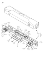
【解決手段】カバー12の内面には、カバー12をベース11に取り付けたときにクリップ14bをケーブル長手方向について中央側に押出すように構成された押出し部材122bが設けられている。押出し部材122bは、カバー12をベース11に取り付けたときに、クリップ部材14bの上面に設けられた斜面又は丸み部分146bに当接する斜面又は丸み部分として構成される。
【選択図】図9
Description
2 メカニカルスプライス
3a、3b ドロップケーブル
11 ベース
12 カバー
13 レバー
14a、14b クリップ
31a、31b 心線
33a、33b 外被
122a′、122b 突状物
123a′、123b′ 水切り板
Claims (5)
- 2つのケーブルが各々有する光ファイバを互いに接続するように構成されたメカニカルスプライスを収容できるメカニカルスプライス設置部を有するベースと、
前記ケーブルを把持して前記ベースに固定するクリップと、
前記ベースと協働して閉鎖体を構成するカバーと、を有し、
前記カバーは、前記ベースに取り付けられて閉鎖体を構成するときに、前記ケーブルを把持している前記クリップの少なくとも一部に当接し、該クリップを前記ケーブルの軸方向に関して前記メカニカルスプライス設置部側に押出す押出し部材を有する、
接続構造体。 - 前記接続構造体は2つのクリップを備え、前記カバーは前記2つのクリップに当接する2つの押出し部材を備える、請求項1に記載の接続構造体。
- 前記押出し部材は、前記ベースに対向する前記カバーの面に設けられた突状物である、請求項1又は2に記載の接続構造体。
- 前記クリップが前記押出し部材によって押出される長さは、温度変化によって前記メカニカルスプライスに接続された前記光ファイバに実質的に張力が生じない程度の長さである、請求項1〜3のいずれか1項に記載の接続構造体。
- 前記クリップは、前記ベースにヒンジによって連結されている、請求項1〜4のいずれか1項に記載の接続構造体。
Priority Applications (3)
| Application Number | Priority Date | Filing Date | Title |
|---|---|---|---|
| JP2008202290A JP5390140B2 (ja) | 2008-08-05 | 2008-08-05 | 光ケーブルの接続構造体 |
| PCT/US2009/034497 WO2009111176A1 (en) | 2008-02-29 | 2009-02-19 | Connecting structure for optical cable |
| TW98106570A TW200942881A (en) | 2008-02-29 | 2009-02-27 | Connecting structure for optical cable |
Applications Claiming Priority (1)
| Application Number | Priority Date | Filing Date | Title |
|---|---|---|---|
| JP2008202290A JP5390140B2 (ja) | 2008-08-05 | 2008-08-05 | 光ケーブルの接続構造体 |
Publications (2)
| Publication Number | Publication Date |
|---|---|
| JP2010039216A true JP2010039216A (ja) | 2010-02-18 |
| JP5390140B2 JP5390140B2 (ja) | 2014-01-15 |
Family
ID=42011838
Family Applications (1)
| Application Number | Title | Priority Date | Filing Date |
|---|---|---|---|
| JP2008202290A Expired - Fee Related JP5390140B2 (ja) | 2008-02-29 | 2008-08-05 | 光ケーブルの接続構造体 |
Country Status (1)
| Country | Link |
|---|---|
| JP (1) | JP5390140B2 (ja) |
Cited By (1)
| Publication number | Priority date | Publication date | Assignee | Title |
|---|---|---|---|---|
| JP2012242451A (ja) * | 2011-05-16 | 2012-12-10 | Three M Innovative Properties Co | 光伝送路接続装置 |
Citations (4)
| Publication number | Priority date | Publication date | Assignee | Title |
|---|---|---|---|---|
| JPH11326696A (ja) * | 1998-05-08 | 1999-11-26 | Yazaki Corp | 光ファイバの接続装置 |
| JP2005208496A (ja) * | 2004-01-26 | 2005-08-04 | Fujikura Ltd | クロージャおよびその組立方法 |
| JP2007093997A (ja) * | 2005-09-28 | 2007-04-12 | Croster Sangyo Kk | 光ファイバ接続装置 |
| JP2008139567A (ja) * | 2006-12-01 | 2008-06-19 | Fujikura Ltd | 光コネクタ |
-
2008
- 2008-08-05 JP JP2008202290A patent/JP5390140B2/ja not_active Expired - Fee Related
Patent Citations (4)
| Publication number | Priority date | Publication date | Assignee | Title |
|---|---|---|---|---|
| JPH11326696A (ja) * | 1998-05-08 | 1999-11-26 | Yazaki Corp | 光ファイバの接続装置 |
| JP2005208496A (ja) * | 2004-01-26 | 2005-08-04 | Fujikura Ltd | クロージャおよびその組立方法 |
| JP2007093997A (ja) * | 2005-09-28 | 2007-04-12 | Croster Sangyo Kk | 光ファイバ接続装置 |
| JP2008139567A (ja) * | 2006-12-01 | 2008-06-19 | Fujikura Ltd | 光コネクタ |
Cited By (1)
| Publication number | Priority date | Publication date | Assignee | Title |
|---|---|---|---|---|
| JP2012242451A (ja) * | 2011-05-16 | 2012-12-10 | Three M Innovative Properties Co | 光伝送路接続装置 |
Also Published As
| Publication number | Publication date |
|---|---|
| JP5390140B2 (ja) | 2014-01-15 |
Similar Documents
| Publication | Publication Date | Title |
|---|---|---|
| US8297850B2 (en) | Optical connector, and method of assembling optical connector | |
| JP4416591B2 (ja) | 光コネクタ及び光ファイバ接続システム | |
| JP3540096B2 (ja) | 光ファイバ接続器 | |
| EP2275847B1 (en) | Optical connector assembling jig and optical connector assembling method | |
| CN102460257B (zh) | 光连接器 | |
| US7712974B2 (en) | Method of assembling an optical connector and an optical connector | |
| JP4205093B2 (ja) | 光コネクタレセプタクル及び光コネクタ | |
| JP2012037624A (ja) | 光コネクタおよび光コネクタ組立ツール | |
| JP5027012B2 (ja) | 光ケーブルの接続構造体 | |
| JP5390140B2 (ja) | 光ケーブルの接続構造体 | |
| JP4191168B2 (ja) | メカニカル接続型光コネクタ | |
| JP2013015787A (ja) | 光コネクタおよびその組立方法 | |
| JP4593660B2 (ja) | 光コネクタ組立工具 | |
| JP4969976B2 (ja) | 光ファイバ心線への光コネクタ取付方法、光ファイバ心線保護チューブ及びそれに用いられる心線仮固定具 | |
| JP5325955B2 (ja) | 光ファイバ接続用ユニット、光ファイバ接続装置および光ファイバの接続方法 | |
| JP2005128139A (ja) | 光ファイバ接続器 | |
| JP2007121878A (ja) | 光コネクタの接続工具 | |
| JP2004078000A (ja) | 光ファイバ接続部材 | |
| JP4732282B2 (ja) | 光ファイバ接続工具 | |
| JP4192750B2 (ja) | 光ファイバ接続部材および光ファイバ接続方法 | |
| JP3778995B2 (ja) | 光ファイバ調心構造 | |
| JP2007121582A (ja) | 光ファイバ心線把持部材及び光コネクタ接続方法 | |
| JP5815657B2 (ja) | 光コネクタ | |
| JP2014174509A (ja) | 光ファイバホルダ及びその構成方法 | |
| HK1257890A1 (zh) | 光连接器以及光连接器的制造方法 |
Legal Events
| Date | Code | Title | Description |
|---|---|---|---|
| A621 | Written request for application examination |
Free format text: JAPANESE INTERMEDIATE CODE: A621 Effective date: 20110801 |
|
| A131 | Notification of reasons for refusal |
Free format text: JAPANESE INTERMEDIATE CODE: A131 Effective date: 20120522 |
|
| A977 | Report on retrieval |
Free format text: JAPANESE INTERMEDIATE CODE: A971007 Effective date: 20120523 |
|
| A601 | Written request for extension of time |
Free format text: JAPANESE INTERMEDIATE CODE: A601 Effective date: 20120822 |
|
| A602 | Written permission of extension of time |
Free format text: JAPANESE INTERMEDIATE CODE: A602 Effective date: 20120827 |
|
| A521 | Written amendment |
Free format text: JAPANESE INTERMEDIATE CODE: A523 Effective date: 20121119 |
|
| A131 | Notification of reasons for refusal |
Free format text: JAPANESE INTERMEDIATE CODE: A131 Effective date: 20130226 |
|
| A601 | Written request for extension of time |
Free format text: JAPANESE INTERMEDIATE CODE: A601 Effective date: 20130527 |
|
| A602 | Written permission of extension of time |
Free format text: JAPANESE INTERMEDIATE CODE: A602 Effective date: 20130531 |
|
| A521 | Written amendment |
Free format text: JAPANESE INTERMEDIATE CODE: A523 Effective date: 20130826 |
|
| TRDD | Decision of grant or rejection written | ||
| A01 | Written decision to grant a patent or to grant a registration (utility model) |
Free format text: JAPANESE INTERMEDIATE CODE: A01 Effective date: 20130910 |
|
| A61 | First payment of annual fees (during grant procedure) |
Free format text: JAPANESE INTERMEDIATE CODE: A61 Effective date: 20131010 |
|
| R150 | Certificate of patent or registration of utility model |
Free format text: JAPANESE INTERMEDIATE CODE: R150 |
|
| R250 | Receipt of annual fees |
Free format text: JAPANESE INTERMEDIATE CODE: R250 |
|
| LAPS | Cancellation because of no payment of annual fees | ||
| S111 | Request for change of ownership or part of ownership |
Free format text: JAPANESE INTERMEDIATE CODE: R313113 |
|
| R360 | Written notification for declining of transfer of rights |
Free format text: JAPANESE INTERMEDIATE CODE: R360 |
|
| R360 | Written notification for declining of transfer of rights |
Free format text: JAPANESE INTERMEDIATE CODE: R360 |
|
| R371 | Transfer withdrawn |
Free format text: JAPANESE INTERMEDIATE CODE: R371 |