JP2010025216A - 駆動輪支持装置 - Google Patents
駆動輪支持装置 Download PDFInfo
- Publication number
- JP2010025216A JP2010025216A JP2008186758A JP2008186758A JP2010025216A JP 2010025216 A JP2010025216 A JP 2010025216A JP 2008186758 A JP2008186758 A JP 2008186758A JP 2008186758 A JP2008186758 A JP 2008186758A JP 2010025216 A JP2010025216 A JP 2010025216A
- Authority
- JP
- Japan
- Prior art keywords
- annular
- ring
- seal ring
- drive wheel
- support device
- Prior art date
- Legal status (The legal status is an assumption and is not a legal conclusion. Google has not performed a legal analysis and makes no representation as to the accuracy of the status listed.)
- Granted
Links
- 238000005096 rolling process Methods 0.000 claims description 31
- 239000002184 metal Substances 0.000 claims description 25
- 229910052751 metal Inorganic materials 0.000 claims description 25
- 238000004073 vulcanization Methods 0.000 claims description 17
- 238000003825 pressing Methods 0.000 claims description 16
- 229920003051 synthetic elastomer Polymers 0.000 claims description 16
- 239000005061 synthetic rubber Substances 0.000 claims description 16
- 229910000831 Steel Inorganic materials 0.000 claims description 9
- 230000002093 peripheral effect Effects 0.000 claims description 9
- 239000010959 steel Substances 0.000 claims description 9
- 125000004122 cyclic group Chemical group 0.000 claims description 5
- XLYOFNOQVPJJNP-UHFFFAOYSA-N water Substances O XLYOFNOQVPJJNP-UHFFFAOYSA-N 0.000 abstract description 3
- 230000004048 modification Effects 0.000 description 20
- 238000012986 modification Methods 0.000 description 20
- 239000003921 oil Substances 0.000 description 11
- 229910000963 austenitic stainless steel Inorganic materials 0.000 description 9
- 239000010960 cold rolled steel Substances 0.000 description 9
- 238000007789 sealing Methods 0.000 description 9
- 239000004519 grease Substances 0.000 description 6
- 229920000459 Nitrile rubber Polymers 0.000 description 5
- 238000006073 displacement reaction Methods 0.000 description 2
- PCHJSUWPFVWCPO-UHFFFAOYSA-N gold Chemical compound [Au] PCHJSUWPFVWCPO-UHFFFAOYSA-N 0.000 description 2
- 239000010931 gold Substances 0.000 description 2
- 229910052737 gold Inorganic materials 0.000 description 2
- 229920006168 hydrated nitrile rubber Polymers 0.000 description 2
- 230000008595 infiltration Effects 0.000 description 2
- 238000001764 infiltration Methods 0.000 description 2
- 238000000034 method Methods 0.000 description 2
- 229920002379 silicone rubber Polymers 0.000 description 2
- OKTJSMMVPCPJKN-UHFFFAOYSA-N Carbon Chemical compound [C] OKTJSMMVPCPJKN-UHFFFAOYSA-N 0.000 description 1
- 229910000669 Chrome steel Inorganic materials 0.000 description 1
- 229920002943 EPDM rubber Polymers 0.000 description 1
- 229910000639 Spring steel Inorganic materials 0.000 description 1
- 229910001315 Tool steel Inorganic materials 0.000 description 1
- NTXGQCSETZTARF-UHFFFAOYSA-N buta-1,3-diene;prop-2-enenitrile Chemical class C=CC=C.C=CC#N NTXGQCSETZTARF-UHFFFAOYSA-N 0.000 description 1
- 229910052799 carbon Inorganic materials 0.000 description 1
- 239000000428 dust Substances 0.000 description 1
- 229920001971 elastomer Polymers 0.000 description 1
- HQQADJVZYDDRJT-UHFFFAOYSA-N ethene;prop-1-ene Chemical group C=C.CC=C HQQADJVZYDDRJT-UHFFFAOYSA-N 0.000 description 1
- 229920001973 fluoroelastomer Polymers 0.000 description 1
- 230000001050 lubricating effect Effects 0.000 description 1
- 229920005559 polyacrylic rubber Polymers 0.000 description 1
- 238000010791 quenching Methods 0.000 description 1
- 230000000171 quenching effect Effects 0.000 description 1
- 239000005060 rubber Substances 0.000 description 1
- 239000004945 silicone rubber Substances 0.000 description 1
- 239000000126 substance Substances 0.000 description 1
Images


Classifications
-
- F—MECHANICAL ENGINEERING; LIGHTING; HEATING; WEAPONS; BLASTING
- F16—ENGINEERING ELEMENTS AND UNITS; GENERAL MEASURES FOR PRODUCING AND MAINTAINING EFFECTIVE FUNCTIONING OF MACHINES OR INSTALLATIONS; THERMAL INSULATION IN GENERAL
- F16C—SHAFTS; FLEXIBLE SHAFTS; ELEMENTS OR CRANKSHAFT MECHANISMS; ROTARY BODIES OTHER THAN GEARING ELEMENTS; BEARINGS
- F16C33/00—Parts of bearings; Special methods for making bearings or parts thereof
- F16C33/30—Parts of ball or roller bearings
- F16C33/58—Raceways; Race rings
- F16C33/60—Raceways; Race rings divided or split, e.g. comprising two juxtaposed rings
-
- F—MECHANICAL ENGINEERING; LIGHTING; HEATING; WEAPONS; BLASTING
- F16—ENGINEERING ELEMENTS AND UNITS; GENERAL MEASURES FOR PRODUCING AND MAINTAINING EFFECTIVE FUNCTIONING OF MACHINES OR INSTALLATIONS; THERMAL INSULATION IN GENERAL
- F16C—SHAFTS; FLEXIBLE SHAFTS; ELEMENTS OR CRANKSHAFT MECHANISMS; ROTARY BODIES OTHER THAN GEARING ELEMENTS; BEARINGS
- F16C19/00—Bearings with rolling contact, for exclusively rotary movement
- F16C19/22—Bearings with rolling contact, for exclusively rotary movement with bearing rollers essentially of the same size in one or more circular rows, e.g. needle bearings
- F16C19/34—Bearings with rolling contact, for exclusively rotary movement with bearing rollers essentially of the same size in one or more circular rows, e.g. needle bearings for both radial and axial load
- F16C19/38—Bearings with rolling contact, for exclusively rotary movement with bearing rollers essentially of the same size in one or more circular rows, e.g. needle bearings for both radial and axial load with two or more rows of rollers
- F16C19/383—Bearings with rolling contact, for exclusively rotary movement with bearing rollers essentially of the same size in one or more circular rows, e.g. needle bearings for both radial and axial load with two or more rows of rollers with tapered rollers, i.e. rollers having essentially the shape of a truncated cone
- F16C19/385—Bearings with rolling contact, for exclusively rotary movement with bearing rollers essentially of the same size in one or more circular rows, e.g. needle bearings for both radial and axial load with two or more rows of rollers with tapered rollers, i.e. rollers having essentially the shape of a truncated cone with two rows, i.e. double-row tapered roller bearings
- F16C19/386—Bearings with rolling contact, for exclusively rotary movement with bearing rollers essentially of the same size in one or more circular rows, e.g. needle bearings for both radial and axial load with two or more rows of rollers with tapered rollers, i.e. rollers having essentially the shape of a truncated cone with two rows, i.e. double-row tapered roller bearings in O-arrangement
-
- F—MECHANICAL ENGINEERING; LIGHTING; HEATING; WEAPONS; BLASTING
- F16—ENGINEERING ELEMENTS AND UNITS; GENERAL MEASURES FOR PRODUCING AND MAINTAINING EFFECTIVE FUNCTIONING OF MACHINES OR INSTALLATIONS; THERMAL INSULATION IN GENERAL
- F16C—SHAFTS; FLEXIBLE SHAFTS; ELEMENTS OR CRANKSHAFT MECHANISMS; ROTARY BODIES OTHER THAN GEARING ELEMENTS; BEARINGS
- F16C33/00—Parts of bearings; Special methods for making bearings or parts thereof
- F16C33/72—Sealings
- F16C33/76—Sealings of ball or roller bearings
- F16C33/768—Sealings of ball or roller bearings between relatively stationary parts, i.e. static seals
-
- F—MECHANICAL ENGINEERING; LIGHTING; HEATING; WEAPONS; BLASTING
- F16—ENGINEERING ELEMENTS AND UNITS; GENERAL MEASURES FOR PRODUCING AND MAINTAINING EFFECTIVE FUNCTIONING OF MACHINES OR INSTALLATIONS; THERMAL INSULATION IN GENERAL
- F16C—SHAFTS; FLEXIBLE SHAFTS; ELEMENTS OR CRANKSHAFT MECHANISMS; ROTARY BODIES OTHER THAN GEARING ELEMENTS; BEARINGS
- F16C2326/00—Articles relating to transporting
- F16C2326/01—Parts of vehicles in general
- F16C2326/02—Wheel hubs or castors
Landscapes
- Engineering & Computer Science (AREA)
- General Engineering & Computer Science (AREA)
- Mechanical Engineering (AREA)
- Sealing Of Bearings (AREA)
- Rolling Contact Bearings (AREA)
Abstract
【解決手段】一対の内輪10、11に環状凹部24が形成され、これに第1のシールリング25が装着されると共に、インナー側の内輪11の端部内周に環状段部26が形成され、これに第2のシールリング27が装着された駆動輪支持装置において、第1のシールリング25が、断面が略L字状に形成され、円筒部28aおよび径方向外方に延びる鍔部28bを有する芯金28と、この芯金28に接合された弾性部材29とで構成されると共に、弾性部材29の内周に、一対の内輪10、11の突き合わせ部の両側に跨架して当接される2条の環状凸条29a、29bがそれぞれ形成され、一方の環状凸条29aの幅寸法aが他方の環状凸条29bの幅寸法bよりも大きく設定されている。
【選択図】図3
Description
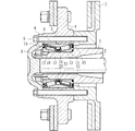
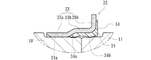
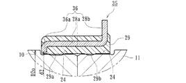
図1は、本発明に係る駆動輪支持装置の一実施形態を示す縦断面図、図2は、その車輪用軸受を示す縦断面図、図3は、図2のA部を示す要部拡大図、図4は、図3の第1のシールリングの変形例を示す要部拡大図、図5は、図3の他の変形例を示す要部拡大図、図6は、同上、他の変形例を示す要部拡大図、図7は、図3に示す第1のシールリングの他の変形例を示す要部拡大図、図8は、図7に示す第1のシールリングの他の変形例を示す要部拡大図、図9は、図2のB部を示す要部拡大図、図10は、図9の第2のシールリングの変形例を示す要部拡大図、図11および図12は、図9の第2のシールリングの他の変形例を示す要部拡大図である。なお、以下の説明では、車両に組み付けた状態で車両の外側寄りとなる側をアウター側(図1の左側)、中央寄り側をインナー側(図1の右側)という。
1a・・・・・・・・・・・・・・・・・・・・・・・・・・・・肩部
2・・・・・・・・・・・・・・・・・・・・・・・・・・・・・駆動軸
3・・・・・・・・・・・・・・・・・・・・・・・・・・・・・複列の円錐ころ軸受
4・・・・・・・・・・・・・・・・・・・・・・・・・・・・・ハブ輪
5・・・・・・・・・・・・・・・・・・・・・・・・・・・・・ハブボルト
6・・・・・・・・・・・・・・・・・・・・・・・・・・・・・フランジ
7・・・・・・・・・・・・・・・・・・・・・・・・・・・・・ブレーキロータ
8・・・・・・・・・・・・・・・・・・・・・・・・・・・・・固定ナット
9・・・・・・・・・・・・・・・・・・・・・・・・・・・・・外輪
9a・・・・・・・・・・・・・・・・・・・・・・・・・・・・外側転走面
10、10’・・・・・・・・・・・・・・・・・・・・・・・・アウター側の内輪
11、11’、11”・・・・・・・・・・・・・・・・・・・・インナー側の内輪
10a・・・・・・・・・・・・・・・・・・・・・・・・・・・内側転走面
10b・・・・・・・・・・・・・・・・・・・・・・・・・・・大鍔部
10c・・・・・・・・・・・・・・・・・・・・・・・・・・・小鍔部
12・・・・・・・・・・・・・・・・・・・・・・・・・・・・保持器
13・・・・・・・・・・・・・・・・・・・・・・・・・・・・円錐ころ
14・・・・・・・・・・・・・・・・・・・・・・・・・・・・アウター側のシール
15・・・・・・・・・・・・・・・・・・・・・・・・・・・・インナー側のシール
16、20、28、33、36、39、44、47・・・・・・・芯金
17、21・・・・・・・・・・・・・・・・・・・・・・・・・シール部材
18・・・・・・・・・・・・・・・・・・・・・・・・・・・・シール板
19・・・・・・・・・・・・・・・・・・・・・・・・・・・・スリンガ
19a、28a、44a・・・・・・・・・・・・・・・・・・・円筒部
19b・・・・・・・・・・・・・・・・・・・・・・・・・・・立板部
21a、21b・・・・・・・・・・・・・・・・・・・・・・・サイドリップ
21c・・・・・・・・・・・・・・・・・・・・・・・・・・・グリースリップ
22・・・・・・・・・・・・・・・・・・・・・・・・・・・・環状溝
23・・・・・・・・・・・・・・・・・・・・・・・・・・・・連結環
24、24’、24a・・・・・・・・・・・・・・・・・・・・環状凹部
25、30、32、35、37・・・・・・・・・・・・・・・・第1のシールリング
26・・・・・・・・・・・・・・・・・・・・・・・・・・・・環状段部
26a・・・・・・・・・・・・・・・・・・・・・・・・・・・ヌスミ部
27、41、43、46・・・・・・・・・・・・・・・・・・・第2のシールリング
28b、36a、47b・・・・・・・・・・・・・・・・・・・鍔部
29、31、34、38、40、42、45、48・・・・・・・弾性部材
29a、29b、31a、31b、34a、34b、38a、38b・・環状凸条
33a・・・・・・・・・・・・・・・・・・・・・・・・・・・第1の円筒部
33b・・・・・・・・・・・・・・・・・・・・・・・・・・・第2の円筒部
40a、45a、48a・・・・・・・・・・・・・・・・・・・リップ
40b、42a・・・・・・・・・・・・・・・・・・・・・・・突起
44b・・・・・・・・・・・・・・・・・・・・・・・・・・・内径部
45b、48b・・・・・・・・・・・・・・・・・・・・・・・嵌合部
47a・・・・・・・・・・・・・・・・・・・・・・・・・・・外径円筒部
47c・・・・・・・・・・・・・・・・・・・・・・・・・・・内径円筒部
49・・・・・・・・・・・・・・・・・・・・・・・・・・・・第1の環状段部
50・・・・・・・・・・・・・・・・・・・・・・・・・・・・第2の環状段部
51・・・・・・・・・・・・・・・・・・・・・・・・・・・・車軸管
52・・・・・・・・・・・・・・・・・・・・・・・・・・・・駆動軸
53・・・・・・・・・・・・・・・・・・・・・・・・・・・・複列の円錐ころ軸受
54・・・・・・・・・・・・・・・・・・・・・・・・・・・・ハブ輪
55・・・・・・・・・・・・・・・・・・・・・・・・・・・・ハブボルト
56・・・・・・・・・・・・・・・・・・・・・・・・・・・・フランジ
57・・・・・・・・・・・・・・・・・・・・・・・・・・・・内輪
58・・・・・・・・・・・・・・・・・・・・・・・・・・・・連結環
59・・・・・・・・・・・・・・・・・・・・・・・・・・・・固定ナット
60・・・・・・・・・・・・・・・・・・・・・・・・・・・・外輪
61・・・・・・・・・・・・・・・・・・・・・・・・・・・・ブレーキロータ
62・・・・・・・・・・・・・・・・・・・・・・・・・・・・円錐ころ
63・・・・・・・・・・・・・・・・・・・・・・・・・・・・保持器
64、64’・・・・・・・・・・・・・・・・・・・・・・・・シール
65・・・・・・・・・・・・・・・・・・・・・・・・・・・・環状段部
66、69・・・・・・・・・・・・・・・・・・・・・・・・・シールリング
67・・・・・・・・・・・・・・・・・・・・・・・・・・・・肩
68・・・・・・・・・・・・・・・・・・・・・・・・・・・・環状凹部
69a・・・・・・・・・・・・・・・・・・・・・・・・・・・芯金
69b・・・・・・・・・・・・・・・・・・・・・・・・・・・弾性部材
70・・・・・・・・・・・・・・・・・・・・・・・・・・・・環状凸条
a、b・・・・・・・・・・・・・・・・・・・・・・・・・・・環状凸条の幅寸法
c・・・・・・・・・・・・・・・・・・・・・・・・・・・・・弾性部材の厚さ
d・・・・・・・・・・・・・・・・・・・・・・・・・・・・・環状凹部の段差
e、f・・・・・・・・・・・・・・・・・・・・・・・・・・・環状凸条の突出量
g・・・・・・・・・・・・・・・・・・・・・・・・・・・・・環状凹部の外径の径差
d2・・・・・・・・・・・・・・・・・・・・・・・・・・・・芯金の鍔部の内径
d3・・・・・・・・・・・・・・・・・・・・・・・・・・・・弾性部材の外径
D1i、D1o・・・・・・・・・・・・・・・・・・・・・・・環状凹部の外径
D2o・・・・・・・・・・・・・・・・・・・・・・・・・・・内輪の小端部側の外径
D3i・・・・・・・・・・・・・・・・・・・・・・・・・・・環状段部の内径
h1、h2・・・・・・・・・・・・・・・・・・・・・・・・・突起の突出量
L1・・・・・・・・・・・・・・・・・・・・・・・・・・・・ヌスミ部の幅
L2・・・・・・・・・・・・・・・・・・・・・・・・・・・・突起の幅
Claims (12)
- 車輪を取り付けるための車輪取付フランジを一体に有するハブ輪と、駆動軸に外嵌された車軸管と、
この車軸管の外径段差部に嵌挿され、前記ハブ輪を回転自在に支持する複列の転がり軸受からなる車輪用軸受とを備えると共に、
この車輪用軸受が、内周に複列の外側転走面が一体に形成された外輪と、
外周に前記複列の外側転走面に対向する内側転走面が形成された一対の内輪と、
これら内輪と前記外輪の各転走面間に保持器を介して転動自在に収容された複列の転動体と、
前記外輪と内輪との間に形成される環状空間の開口部に装着されたシールとを備え、
前記一対の内輪の突合せ部外周面に環状凹部が形成され、この環状凹部に第1のシールリングが装着されると共に、
前記一対の内輪のうちインナー側の内輪の端部内周に環状段部が形成され、この環状段部に第2のシールリングが装着された駆動輪支持装置において、
前記第1のシールリングが、鋼鈑からプレス加工にて断面が略L字状に形成され、円筒部およびこの円筒部から径方向外方に延びる鍔部を有する芯金と、この芯金に加硫接着により一体に接合された合成ゴムからなる弾性部材とで構成されていることを特徴とする駆動輪支持装置。 - 前記弾性部材の内周に、前記一対の内輪の突き合わせ部の両側に跨架して当接される環状凸条がそれぞれ形成されている請求項1に記載の駆動輪支持装置。
- 前記環状凸条の間に嵌合力の差が生じる手段が施されている請求項1または2に記載の駆動輪支持装置。
- 前記環状凸条のうち一方の環状凸条の幅寸法が他方の環状凸条の幅寸法よりも大きく設定されている請求項3に記載の駆動輪支持装置。
- 前記環状凸条のうち一方の環状凸条の突出量が他方の環状凸条の突出量よりも大きく設定されている請求項3に記載の駆動輪支持装置。
- 前記一対の内輪のうち一方の内輪における環状凹部の外径が他方の内輪における環状凹部の外径よりも大径に設定されている請求項3に記載の駆動輪支持装置。
- 前記芯金が、前記内輪の環状凹部に圧入される第1の円筒部と、この第1の円筒部から僅かに大径に形成された第2の円筒部とを備えている請求項3に記載の駆動輪支持装置。
- 前記環状凸条に、さらにこれら環状凸条よりも小さな環状凸条がそれぞれ形成されている請求項1乃至7いずれかに記載の駆動輪支持装置。
- 前記第1のシールリングにおける弾性部材の内径側の厚さが、前記環状凹部の段差よりも小さく設定されている請求項1乃至6および8いずれかに記載の駆動輪支持装置。
- 前記芯金が、前記円筒部から径方向内方に延びる鍔部を備え、この鍔部の内径が、前記環状凹部が形成された当該内輪の小径側の外径よりも小径に設定されている請求項1乃至6および8いずれかに記載の駆動輪支持装置。
- 前記第2のシールリングが、鋼鈑からプレス加工にて形成された芯金と、この芯金に加硫接着により一体に接合された合成ゴムからなる弾性部材とで形成され、この弾性部材が、前記車軸管の肩部に当接するリップと、外径部に径方向に突出した環状の突起と、端部に軸方向に突出した環状の突起がそれぞれ形成され、これらの突起が前記環状段部に弾性変形した状態で装着されている請求項1乃至10いずれかに記載の駆動輪支持装置。
- 前記内輪の環状段部が、第1の環状段部と、この第1の環状段部よりも小径の第2の環状段部で構成されると共に、前記第2のシールリングが、鋼鈑からプレス加工にて外径円筒部と、この外径円筒部から径方向内方に延びる鍔部と、この鍔部から軸受内方側に延びる内径円筒部とを有する断面略クランク形状に形成された芯金と、この芯金に加硫接着により一体に接合された合成ゴムからなり、前記車軸管の肩部に当接するリップを有する弾性部材とで構成され、前記第2の環状段部に当該第2のシールリングの内径円筒部が装着されている請求項1乃至10いずれかに記載の駆動輪支持装置。
Priority Applications (1)
| Application Number | Priority Date | Filing Date | Title |
|---|---|---|---|
| JP2008186758A JP5252489B2 (ja) | 2008-07-18 | 2008-07-18 | 駆動輪支持装置 |
Applications Claiming Priority (1)
| Application Number | Priority Date | Filing Date | Title |
|---|---|---|---|
| JP2008186758A JP5252489B2 (ja) | 2008-07-18 | 2008-07-18 | 駆動輪支持装置 |
Publications (2)
| Publication Number | Publication Date |
|---|---|
| JP2010025216A true JP2010025216A (ja) | 2010-02-04 |
| JP5252489B2 JP5252489B2 (ja) | 2013-07-31 |
Family
ID=41731246
Family Applications (1)
| Application Number | Title | Priority Date | Filing Date |
|---|---|---|---|
| JP2008186758A Active JP5252489B2 (ja) | 2008-07-18 | 2008-07-18 | 駆動輪支持装置 |
Country Status (1)
| Country | Link |
|---|---|
| JP (1) | JP5252489B2 (ja) |
Cited By (10)
| Publication number | Priority date | Publication date | Assignee | Title |
|---|---|---|---|---|
| JP2011251649A (ja) * | 2010-06-03 | 2011-12-15 | Ntn Corp | 車輪用軸受装置 |
| JP2014178006A (ja) * | 2013-03-15 | 2014-09-25 | Ntn Corp | 密封装置付き軸受装置 |
| JP2015016778A (ja) * | 2013-07-11 | 2015-01-29 | Ntn株式会社 | 車輪用軸受装置 |
| WO2015092099A1 (es) * | 2013-12-19 | 2015-06-25 | Fersa Innova, S.L.U. | Junta de estanqueidad |
| JP2015212567A (ja) * | 2014-05-07 | 2015-11-26 | 日本精工株式会社 | 転がり軸受 |
| JP2017020610A (ja) * | 2015-07-14 | 2017-01-26 | 株式会社ジェイテクト | 車輪用軸受装置 |
| DE102015220151A1 (de) * | 2015-10-16 | 2017-04-20 | Aktiebolaget Skf | Lageranordnung und Dichtung |
| JP2018002148A (ja) * | 2017-09-08 | 2018-01-11 | Ntn株式会社 | 車輪用軸受装置 |
| DE102016218134A1 (de) * | 2016-09-21 | 2018-03-22 | Schaeffler Technologies AG & Co. KG | Lageranordnung mit einstellbarer Lagervorspannung |
| WO2021093914A1 (de) * | 2019-11-11 | 2021-05-20 | Schaeffler Technologies AG & Co. KG | Radlagereinheit |
Citations (4)
| Publication number | Priority date | Publication date | Assignee | Title |
|---|---|---|---|---|
| JP2000104747A (ja) * | 1998-07-29 | 2000-04-11 | Nsk Ltd | 密封転がり軸受 |
| JP2001099172A (ja) * | 1999-09-27 | 2001-04-10 | Ntn Corp | 駆動輪支持装置 |
| JP2007187218A (ja) * | 2006-01-12 | 2007-07-26 | Ntn Corp | 車輪用軸受装置 |
| JP2008075834A (ja) * | 2006-09-25 | 2008-04-03 | Jtekt Corp | 転がり軸受装置 |
-
2008
- 2008-07-18 JP JP2008186758A patent/JP5252489B2/ja active Active
Patent Citations (4)
| Publication number | Priority date | Publication date | Assignee | Title |
|---|---|---|---|---|
| JP2000104747A (ja) * | 1998-07-29 | 2000-04-11 | Nsk Ltd | 密封転がり軸受 |
| JP2001099172A (ja) * | 1999-09-27 | 2001-04-10 | Ntn Corp | 駆動輪支持装置 |
| JP2007187218A (ja) * | 2006-01-12 | 2007-07-26 | Ntn Corp | 車輪用軸受装置 |
| JP2008075834A (ja) * | 2006-09-25 | 2008-04-03 | Jtekt Corp | 転がり軸受装置 |
Cited By (13)
| Publication number | Priority date | Publication date | Assignee | Title |
|---|---|---|---|---|
| JP2011251649A (ja) * | 2010-06-03 | 2011-12-15 | Ntn Corp | 車輪用軸受装置 |
| JP2014178006A (ja) * | 2013-03-15 | 2014-09-25 | Ntn Corp | 密封装置付き軸受装置 |
| JP2015016778A (ja) * | 2013-07-11 | 2015-01-29 | Ntn株式会社 | 車輪用軸受装置 |
| WO2015092099A1 (es) * | 2013-12-19 | 2015-06-25 | Fersa Innova, S.L.U. | Junta de estanqueidad |
| JP2015212567A (ja) * | 2014-05-07 | 2015-11-26 | 日本精工株式会社 | 転がり軸受 |
| JP2017020610A (ja) * | 2015-07-14 | 2017-01-26 | 株式会社ジェイテクト | 車輪用軸受装置 |
| DE102015220151A1 (de) * | 2015-10-16 | 2017-04-20 | Aktiebolaget Skf | Lageranordnung und Dichtung |
| DE102016218134A1 (de) * | 2016-09-21 | 2018-03-22 | Schaeffler Technologies AG & Co. KG | Lageranordnung mit einstellbarer Lagervorspannung |
| JP2018002148A (ja) * | 2017-09-08 | 2018-01-11 | Ntn株式会社 | 車輪用軸受装置 |
| WO2021093914A1 (de) * | 2019-11-11 | 2021-05-20 | Schaeffler Technologies AG & Co. KG | Radlagereinheit |
| CN114402144A (zh) * | 2019-11-11 | 2022-04-26 | 舍弗勒技术股份两合公司 | 轮轴承单元 |
| US11965554B2 (en) | 2019-11-11 | 2024-04-23 | Schaeffler Technologies AG & Co. KG | Wheel bearing unit |
| CN114402144B (zh) * | 2019-11-11 | 2025-02-14 | 舍弗勒技术股份两合公司 | 轮轴承单元 |
Also Published As
| Publication number | Publication date |
|---|---|
| JP5252489B2 (ja) | 2013-07-31 |
Similar Documents
| Publication | Publication Date | Title |
|---|---|---|
| JP5252489B2 (ja) | 駆動輪支持装置 | |
| JP6275465B2 (ja) | 密封装置およびこれを備えた車輪用軸受装置 | |
| JP5469497B2 (ja) | 車輪用軸受装置 | |
| US8449197B2 (en) | Bearing apparatus for a wheel of vehicle | |
| JP5560090B2 (ja) | 車輪用軸受装置 | |
| JP6730786B2 (ja) | 車輪用軸受装置 | |
| JP2016186319A (ja) | 密封装置およびこれを備えた車輪用軸受装置 | |
| JP2012056411A (ja) | 車輪用軸受装置 | |
| CN101506536B (zh) | 车轮用轴承装置 | |
| JP2011027130A (ja) | 車輪用軸受装置 | |
| JP2011148409A (ja) | 車輪用軸受装置 | |
| JP2011069458A (ja) | 車輪用軸受装置 | |
| JP2016003709A (ja) | 車輪用軸受装置 | |
| JP6235256B2 (ja) | 車輪用軸受装置 | |
| CN101529106A (zh) | 车轮用轴承装置 | |
| JP6534458B2 (ja) | 密封装置およびこれを備えた車輪用軸受装置 | |
| JP2011251649A (ja) | 車輪用軸受装置 | |
| JP2005226787A (ja) | 軸受用密封装置 | |
| JP5414964B2 (ja) | 車輪用軸受装置 | |
| JP2010001969A (ja) | 車輪用軸受シールおよびこれを備えた車輪用軸受装置 | |
| JP6396681B2 (ja) | 車輪用軸受装置 | |
| JP6629802B2 (ja) | 車輪用軸受装置 | |
| JP6483460B2 (ja) | 密封装置およびこれを備えた車輪用軸受装置 | |
| JP2013040664A (ja) | 車輪用軸受装置 | |
| JP4854324B2 (ja) | 車輪用軸受装置のシール圧入方法 |
Legal Events
| Date | Code | Title | Description |
|---|---|---|---|
| A621 | Written request for application examination |
Free format text: JAPANESE INTERMEDIATE CODE: A621 Effective date: 20110629 |
|
| A131 | Notification of reasons for refusal |
Free format text: JAPANESE INTERMEDIATE CODE: A131 Effective date: 20120523 |
|
| A977 | Report on retrieval |
Free format text: JAPANESE INTERMEDIATE CODE: A971007 Effective date: 20120524 |
|
| A521 | Request for written amendment filed |
Free format text: JAPANESE INTERMEDIATE CODE: A523 Effective date: 20120717 |
|
| A02 | Decision of refusal |
Free format text: JAPANESE INTERMEDIATE CODE: A02 Effective date: 20130111 |
|
| A521 | Request for written amendment filed |
Free format text: JAPANESE INTERMEDIATE CODE: A523 Effective date: 20130313 |
|
| A911 | Transfer to examiner for re-examination before appeal (zenchi) |
Free format text: JAPANESE INTERMEDIATE CODE: A911 Effective date: 20130321 |
|
| TRDD | Decision of grant or rejection written | ||
| A01 | Written decision to grant a patent or to grant a registration (utility model) |
Free format text: JAPANESE INTERMEDIATE CODE: A01 Effective date: 20130410 |
|
| A61 | First payment of annual fees (during grant procedure) |
Free format text: JAPANESE INTERMEDIATE CODE: A61 Effective date: 20130410 |
|
| R150 | Certificate of patent or registration of utility model |
Ref document number: 5252489 Country of ref document: JP Free format text: JAPANESE INTERMEDIATE CODE: R150 Free format text: JAPANESE INTERMEDIATE CODE: R150 |
|
| FPAY | Renewal fee payment (event date is renewal date of database) |
Free format text: PAYMENT UNTIL: 20160426 Year of fee payment: 3 |
|
| R250 | Receipt of annual fees |
Free format text: JAPANESE INTERMEDIATE CODE: R250 |
|
| R250 | Receipt of annual fees |
Free format text: JAPANESE INTERMEDIATE CODE: R250 |
|
| R250 | Receipt of annual fees |
Free format text: JAPANESE INTERMEDIATE CODE: R250 |
|
| R250 | Receipt of annual fees |
Free format text: JAPANESE INTERMEDIATE CODE: R250 |
|
| R250 | Receipt of annual fees |
Free format text: JAPANESE INTERMEDIATE CODE: R250 |
|
| R250 | Receipt of annual fees |
Free format text: JAPANESE INTERMEDIATE CODE: R250 |
|
| R250 | Receipt of annual fees |
Free format text: JAPANESE INTERMEDIATE CODE: R250 |
|
| R250 | Receipt of annual fees |
Free format text: JAPANESE INTERMEDIATE CODE: R250 |
|
| R250 | Receipt of annual fees |
Free format text: JAPANESE INTERMEDIATE CODE: R250 |
|
| R250 | Receipt of annual fees |
Free format text: JAPANESE INTERMEDIATE CODE: R250 |