JP2010025216A - Drive wheel supporting device - Google Patents
Drive wheel supporting device Download PDFInfo
- Publication number
- JP2010025216A JP2010025216A JP2008186758A JP2008186758A JP2010025216A JP 2010025216 A JP2010025216 A JP 2010025216A JP 2008186758 A JP2008186758 A JP 2008186758A JP 2008186758 A JP2008186758 A JP 2008186758A JP 2010025216 A JP2010025216 A JP 2010025216A
- Authority
- JP
- Japan
- Prior art keywords
- annular
- ring
- seal ring
- drive wheel
- support device
- Prior art date
- Legal status (The legal status is an assumption and is not a legal conclusion. Google has not performed a legal analysis and makes no representation as to the accuracy of the status listed.)
- Granted
Links
- 238000005096 rolling process Methods 0.000 claims description 31
- 239000002184 metal Substances 0.000 claims description 25
- 229910052751 metal Inorganic materials 0.000 claims description 25
- 238000004073 vulcanization Methods 0.000 claims description 17
- 238000003825 pressing Methods 0.000 claims description 16
- 229920003051 synthetic elastomer Polymers 0.000 claims description 16
- 239000005061 synthetic rubber Substances 0.000 claims description 16
- 229910000831 Steel Inorganic materials 0.000 claims description 9
- 230000002093 peripheral effect Effects 0.000 claims description 9
- 239000010959 steel Substances 0.000 claims description 9
- 125000004122 cyclic group Chemical group 0.000 claims description 5
- 239000002002 slurry Substances 0.000 abstract 1
- 230000004048 modification Effects 0.000 description 20
- 238000012986 modification Methods 0.000 description 20
- 239000003921 oil Substances 0.000 description 11
- 229910000963 austenitic stainless steel Inorganic materials 0.000 description 9
- 239000010960 cold rolled steel Substances 0.000 description 9
- 238000007789 sealing Methods 0.000 description 9
- 239000004519 grease Substances 0.000 description 6
- 229920000459 Nitrile rubber Polymers 0.000 description 5
- 238000006073 displacement reaction Methods 0.000 description 2
- PCHJSUWPFVWCPO-UHFFFAOYSA-N gold Chemical compound [Au] PCHJSUWPFVWCPO-UHFFFAOYSA-N 0.000 description 2
- 239000010931 gold Substances 0.000 description 2
- 229910052737 gold Inorganic materials 0.000 description 2
- 229920006168 hydrated nitrile rubber Polymers 0.000 description 2
- 230000008595 infiltration Effects 0.000 description 2
- 238000001764 infiltration Methods 0.000 description 2
- 238000000034 method Methods 0.000 description 2
- 229920002379 silicone rubber Polymers 0.000 description 2
- XLYOFNOQVPJJNP-UHFFFAOYSA-N water Substances O XLYOFNOQVPJJNP-UHFFFAOYSA-N 0.000 description 2
- OKTJSMMVPCPJKN-UHFFFAOYSA-N Carbon Chemical compound [C] OKTJSMMVPCPJKN-UHFFFAOYSA-N 0.000 description 1
- 229910000669 Chrome steel Inorganic materials 0.000 description 1
- 229920002943 EPDM rubber Polymers 0.000 description 1
- 229910000639 Spring steel Inorganic materials 0.000 description 1
- 229910001315 Tool steel Inorganic materials 0.000 description 1
- NTXGQCSETZTARF-UHFFFAOYSA-N buta-1,3-diene;prop-2-enenitrile Chemical class C=CC=C.C=CC#N NTXGQCSETZTARF-UHFFFAOYSA-N 0.000 description 1
- 229910052799 carbon Inorganic materials 0.000 description 1
- 239000000428 dust Substances 0.000 description 1
- 229920001971 elastomer Polymers 0.000 description 1
- HQQADJVZYDDRJT-UHFFFAOYSA-N ethene;prop-1-ene Chemical group C=C.CC=C HQQADJVZYDDRJT-UHFFFAOYSA-N 0.000 description 1
- 229920001973 fluoroelastomer Polymers 0.000 description 1
- 230000001050 lubricating effect Effects 0.000 description 1
- 229920005559 polyacrylic rubber Polymers 0.000 description 1
- 238000010791 quenching Methods 0.000 description 1
- 230000000171 quenching effect Effects 0.000 description 1
- 239000005060 rubber Substances 0.000 description 1
- 239000004945 silicone rubber Substances 0.000 description 1
- 239000000126 substance Substances 0.000 description 1
Images


Classifications
-
- F—MECHANICAL ENGINEERING; LIGHTING; HEATING; WEAPONS; BLASTING
- F16—ENGINEERING ELEMENTS AND UNITS; GENERAL MEASURES FOR PRODUCING AND MAINTAINING EFFECTIVE FUNCTIONING OF MACHINES OR INSTALLATIONS; THERMAL INSULATION IN GENERAL
- F16C—SHAFTS; FLEXIBLE SHAFTS; ELEMENTS OR CRANKSHAFT MECHANISMS; ROTARY BODIES OTHER THAN GEARING ELEMENTS; BEARINGS
- F16C33/00—Parts of bearings; Special methods for making bearings or parts thereof
- F16C33/30—Parts of ball or roller bearings
- F16C33/58—Raceways; Race rings
- F16C33/60—Raceways; Race rings divided or split, e.g. comprising two juxtaposed rings
-
- F—MECHANICAL ENGINEERING; LIGHTING; HEATING; WEAPONS; BLASTING
- F16—ENGINEERING ELEMENTS AND UNITS; GENERAL MEASURES FOR PRODUCING AND MAINTAINING EFFECTIVE FUNCTIONING OF MACHINES OR INSTALLATIONS; THERMAL INSULATION IN GENERAL
- F16C—SHAFTS; FLEXIBLE SHAFTS; ELEMENTS OR CRANKSHAFT MECHANISMS; ROTARY BODIES OTHER THAN GEARING ELEMENTS; BEARINGS
- F16C19/00—Bearings with rolling contact, for exclusively rotary movement
- F16C19/22—Bearings with rolling contact, for exclusively rotary movement with bearing rollers essentially of the same size in one or more circular rows, e.g. needle bearings
- F16C19/34—Bearings with rolling contact, for exclusively rotary movement with bearing rollers essentially of the same size in one or more circular rows, e.g. needle bearings for both radial and axial load
- F16C19/38—Bearings with rolling contact, for exclusively rotary movement with bearing rollers essentially of the same size in one or more circular rows, e.g. needle bearings for both radial and axial load with two or more rows of rollers
- F16C19/383—Bearings with rolling contact, for exclusively rotary movement with bearing rollers essentially of the same size in one or more circular rows, e.g. needle bearings for both radial and axial load with two or more rows of rollers with tapered rollers, i.e. rollers having essentially the shape of a truncated cone
- F16C19/385—Bearings with rolling contact, for exclusively rotary movement with bearing rollers essentially of the same size in one or more circular rows, e.g. needle bearings for both radial and axial load with two or more rows of rollers with tapered rollers, i.e. rollers having essentially the shape of a truncated cone with two rows, i.e. double-row tapered roller bearings
- F16C19/386—Bearings with rolling contact, for exclusively rotary movement with bearing rollers essentially of the same size in one or more circular rows, e.g. needle bearings for both radial and axial load with two or more rows of rollers with tapered rollers, i.e. rollers having essentially the shape of a truncated cone with two rows, i.e. double-row tapered roller bearings in O-arrangement
-
- F—MECHANICAL ENGINEERING; LIGHTING; HEATING; WEAPONS; BLASTING
- F16—ENGINEERING ELEMENTS AND UNITS; GENERAL MEASURES FOR PRODUCING AND MAINTAINING EFFECTIVE FUNCTIONING OF MACHINES OR INSTALLATIONS; THERMAL INSULATION IN GENERAL
- F16C—SHAFTS; FLEXIBLE SHAFTS; ELEMENTS OR CRANKSHAFT MECHANISMS; ROTARY BODIES OTHER THAN GEARING ELEMENTS; BEARINGS
- F16C33/00—Parts of bearings; Special methods for making bearings or parts thereof
- F16C33/72—Sealings
- F16C33/76—Sealings of ball or roller bearings
- F16C33/768—Sealings of ball or roller bearings between relatively stationary parts, i.e. static seals
-
- F—MECHANICAL ENGINEERING; LIGHTING; HEATING; WEAPONS; BLASTING
- F16—ENGINEERING ELEMENTS AND UNITS; GENERAL MEASURES FOR PRODUCING AND MAINTAINING EFFECTIVE FUNCTIONING OF MACHINES OR INSTALLATIONS; THERMAL INSULATION IN GENERAL
- F16C—SHAFTS; FLEXIBLE SHAFTS; ELEMENTS OR CRANKSHAFT MECHANISMS; ROTARY BODIES OTHER THAN GEARING ELEMENTS; BEARINGS
- F16C2326/00—Articles relating to transporting
- F16C2326/01—Parts of vehicles in general
- F16C2326/02—Wheel hubs or castors
Abstract
Description
本発明は、トラック等の車両の駆動輪を複列の転がり軸受で回転自在に支承する駆動輪支持装置に関するものである。 The present invention relates to a drive wheel support device that rotatably supports a drive wheel of a vehicle such as a truck with a double row rolling bearing.
トラック等のようにフレーム構造の車体を有する自動車では、駆動輪のアクスル構造として、従来フルフローティングタイプを採用するものが多い。また、最近の駆動輪の支持構造には、組立性の向上、軽量・コンパクト化等を狙って、複列の転がり軸受をユニット化した構造が多く採用されるようになっている。その従来構造の一例として、図13に示すような車輪用軸受装置が知られている。 Many automobiles having a frame-structured body such as a truck adopt a conventional full floating type as an axle structure of a drive wheel. Also, recent drive wheel support structures are often adopted as a structure in which double row rolling bearings are unitized for the purpose of improving assemblability and reducing weight and size. As an example of the conventional structure, a wheel bearing device as shown in FIG. 13 is known.
この車輪用軸受装置は、車軸管51の中にデファレンシャル(図示せず)と連結された駆動軸52が挿通され、車軸管51の外径面に複列の円錐ころ軸受53が装着されている。この複列の円錐ころ軸受53により回転自在に支承されたハブ輪54が、ハブボルト55を介して駆動軸52のフランジ56に連結されている。複列の円錐ころ軸受53の内輪57は、左右一対のものが連結環58で結合され、車軸管51の端部に外嵌されると共に、固定ナット59で締付固定されている。複列の円錐ころ軸受53の外輪60は、ハブ輪54に内嵌され、その両端をフランジ56とブレーキロータ61により挟持された状態で軸方向に固定されている。これら内外輪57、60間の環状空間には、複列の円錐ころ62が保持器63により回転自在に収容され、両端部にはシール64、64’が装着されて軸受内部が密封されている。
In this wheel bearing device, a
図14に示すように、内輪57の内方端部には環状段部65が形成され、第2の密封リングとしてのOリングからなるシールリング66が装着されている。そして、車軸管51の外径段差部の肩67の角半径に当接されて、内輪57と車軸管51の間の僅かな隙間が遮断されている。これにより、この僅かな隙間から泥水の浸入やデフオイルの外部への漏れを防止している。また、図15に示すように、一対の内輪57、57の突合せ部外周面には環状凹部68が形成され、この環状凹部68に第1の密封リングとしてのシールリング69が装着されている。このシールリング69は、芯金69aと弾性部材69bとで形成され、弾性部材69bの内周には、突き合わせ部の両側に跨架して当接される2条の環状凸条70が形成されている。これにより、軸受内部へのデフオイルの浸入を防止している。
然しながら、このような従来の車輪用軸受装置において、第2の密封リングとしてシールリング66は、内輪57の環状段部65に装着されているものの位置決めが完全ではなく、軸受搬送時に脱落する恐れがあった。一方、第1の密封リングとしてのシールリング69は、一対の内輪57、57の突合せ部外周面に形成された環状凹部68に装着されているが、シールリング69を一方の内輪57に圧入した後、他方の内輪57がこのシールリング69の内径に圧入されるため、シールリング69と他方の内輪57との軸芯が一致していない場合、内輪57の端面でシールリング69を押すことになり、シールリング69の位置がずれる恐れがある。特に、このシールリング69は、組立後に正規の位置に装着されているかどうかの確認が困難なため、信頼性の面で課題があった。
However, in such a conventional wheel bearing device, although the
本発明は、このような従来の問題に鑑みてなされたもので、泥水の浸入とデフオイルの漏れを防止することができ、かつ、軸受内部へのデフオイルの浸入を防止できる駆動輪支持装置を提供することを目的とする。 The present invention has been made in view of such conventional problems, and provides a drive wheel support device that can prevent the intrusion of muddy water and the leakage of differential oil, and can prevent the ingress of differential oil into the bearing. The purpose is to do.
係る目的を達成すべく、本発明のうち請求項1に記載の発明は、車輪を取り付けるための車輪取付フランジを一体に有するハブ輪と、駆動軸に外嵌された車軸管と、この車軸管の外径段差部に嵌挿され、前記ハブ輪を回転自在に支持する複列の転がり軸受からなる車輪用軸受とを備えると共に、この車輪用軸受が、内周に複列の外側転走面が一体に形成された外輪と、外周に前記複列の外側転走面に対向する内側転走面が形成された一対の内輪と、これら内輪と前記外輪の各転走面間に保持器を介して転動自在に収容された複列の転動体と、前記外輪と内輪との間に形成される環状空間の開口部に装着されたシールとを備え、前記一対の内輪の突合せ部外周面に環状凹部が形成され、この環状凹部に第1のシールリングが装着されると共に、前記一対の内輪のうちインナー側の内輪の端部内周に環状段部が形成され、この環状段部に第2のシールリングが装着された駆動輪支持装置において、前記第1のシールリングが、鋼鈑からプレス加工にて断面が略L字状に形成され、円筒部およびこの円筒部から径方向外方に延びる鍔部を有する芯金と、この芯金に加硫接着により一体に接合された合成ゴムからなる弾性部材とで構成されている。 In order to achieve such an object, the invention according to claim 1 of the present invention includes a hub wheel integrally having a wheel mounting flange for mounting a wheel, an axle tube externally fitted to a drive shaft, and the axle tube. And a wheel bearing comprising a double row rolling bearing that rotatably supports the hub wheel, and the wheel bearing has a double row outer rolling surface on the inner periphery. Is formed integrally with the outer ring, a pair of inner rings formed on the outer periphery with an inner rolling surface facing the outer rolling surface of the double row, and a cage is provided between the rolling surfaces of the inner ring and the outer ring. A plurality of rolling elements accommodated so as to be freely rollable, and a seal attached to an opening of an annular space formed between the outer ring and the inner ring, and an outer peripheral surface of the butted portion of the pair of inner rings An annular recess is formed, and a first seal ring is attached to the annular recess, In the driving wheel support device in which an annular step is formed on the inner periphery of the inner ring on the inner side of the pair of inner rings, and the second seal ring is attached to the annular step, the first seal ring includes: A metal core having a cylindrical portion and a flange portion extending radially outward from the cylindrical portion is integrally joined to the metal core by vulcanization bonding. And an elastic member made of synthetic rubber.
このように、一対の内輪の突合せ部外周面に環状凹部が形成され、この環状凹部に第1のシールリングが装着されると共に、一対の内輪のうちインナー側の内輪の端部内周に環状段部が形成され、この環状段部に第2のシールリングが装着された駆動輪支持装置において、第1のシールリングが、鋼鈑からプレス加工にて断面が略L字状に形成され、円筒部およびこの円筒部から径方向外方に延びる鍔部を有する芯金と、この芯金に加硫接着により一体に接合された合成ゴムからなる弾性部材とで構成されているので、芯金の剛性を高めて圧入時の変形を抑制し、位置決め精度を確保することによって信頼性を向上させ、軸受内部へのデフオイルの浸入を確実に防止することができる。 As described above, an annular recess is formed on the outer peripheral surface of the abutting portion of the pair of inner rings, the first seal ring is mounted on the annular recess, and an annular step is formed on the inner periphery of the inner ring on the inner side of the pair of inner rings. In the drive wheel support device in which the second seal ring is mounted on the annular step portion, the first seal ring is formed into a substantially L-shaped cross section by pressing from a steel plate, and is cylindrical. And a cored bar having a flange extending radially outward from the cylindrical part, and an elastic member made of synthetic rubber integrally joined to the cored bar by vulcanization adhesion. By increasing the rigidity to suppress deformation during press-fitting and ensuring positioning accuracy, the reliability can be improved and the infiltration of differential oil into the bearing can be reliably prevented.
好ましくは、請求項2に記載の発明は、前記弾性部材の内周に、前記一対の内輪の突き合わせ部の両側に跨架して当接される環状凸条がそれぞれ形成されていれば、第1のシールリングの気密性を高めることができる。 Preferably, in the invention described in claim 2, if the annular protrusions straddling and abutting on both sides of the butted portions of the pair of inner rings are respectively formed on the inner periphery of the elastic member, The airtightness of the seal ring 1 can be improved.
また、請求項3に記載の発明のように、前記環状凸条の間に嵌合力の差が生じる手段が施されていれば、予め第1のシールリングを一方の内輪の環状凹部に圧入した後、第1のシールリングの内径に他方の内輪を圧入する時、この嵌合力の差によって第1のシールリングが位置ずれを起すことはなく、位置決め精度を確保することができる。 Further, as in the third aspect of the invention, if a means for generating a difference in fitting force is provided between the annular ridges, the first seal ring is previously press-fitted into the annular recess of one inner ring. Thereafter, when the other inner ring is press-fitted into the inner diameter of the first seal ring, the first seal ring will not be displaced due to this difference in fitting force, and positioning accuracy can be ensured.
また、請求項4に記載の発明のように、前記環状凸条のうち一方の環状凸条の幅寸法が他方の環状凸条の幅寸法よりも大きく設定されていても良い。 Moreover, like invention of Claim 4, the width dimension of one cyclic | annular ridge among the said cyclic | annular ridges may be set larger than the width dimension of the other cyclic | annular ridge.
また、請求項5に記載の発明のように、前記環状凸条のうち一方の環状凸条の突出量が他方の環状凸条の突出量よりも大きく設定されていても良い。
Moreover, like the invention of
また、請求項6に記載の発明のように、前記一対の内輪のうち一方の内輪における環状凹部の外径が他方の内輪における環状凹部の外径よりも大径に設定されていても良い。 Further, as in the invention described in claim 6, the outer diameter of the annular recess in one inner ring of the pair of inner rings may be set larger than the outer diameter of the annular recess in the other inner ring.
また、請求項7に記載の発明のように、前記芯金が、前記内輪の環状凹部に圧入される第1の円筒部と、この第1の円筒部から僅かに大径に形成された第2の円筒部とを備えていれば、芯金の剛性を確保して圧入時の変形を抑制すると共に、予め第1のシールリングを一方の内輪の環状凹部に圧入した後、第1のシールリングの内径に他方の内輪を圧入する時、この嵌合力の差によって第1のシールリングが位置ずれを起すことはない。 According to a seventh aspect of the present invention, the metal core is a first cylindrical portion that is press-fitted into the annular concave portion of the inner ring, and a first cylindrical portion that is formed to have a slightly larger diameter from the first cylindrical portion. If the second cylindrical portion is provided, the rigidity of the core bar is secured to prevent deformation at the time of press-fitting, and the first seal ring is previously press-fitted into the annular recess of one inner ring, and then the first seal When the other inner ring is press-fitted into the inner diameter of the ring, the first seal ring is not displaced due to the difference in the fitting force.
また、請求項8に記載の発明のように、前記環状凸条に、さらにこれら環状凸条よりも小さな環状凸条がそれぞれ形成されていれば、第1のシールリングの密封性が向上し、一対の内輪の突合せ部から軸受内部へデフオイルが浸入するのを確実に防止することができる。
Further, as in the invention described in
また、請求項9に記載の発明のように、前記第1のシールリングにおける弾性部材の内径側の厚さが、前記環状凹部の段差よりも小さく設定されていれば、第1のシールリングの内径に他方の内輪を圧入する時、第1のシールリングとこの内輪との間に芯違いがあって内輪の端面によって第1のシールリングを押すようなことがあっても、芯金が内輪の環状凹部に確実に衝合するため大きな位置ずれを起すことなく精度良く位置決め固定することができる。 As in the ninth aspect of the invention, if the inner diameter side thickness of the elastic member in the first seal ring is set smaller than the step of the annular recess, the first seal ring When the other inner ring is press-fitted into the inner diameter, even if there is a misalignment between the first seal ring and the inner ring and the first seal ring is pushed by the end face of the inner ring, Therefore, it can be positioned and fixed with high accuracy without causing a large displacement.
また、請求項10に記載の発明のように、前記芯金が、前記円筒部から径方向内方に延びる鍔部を備え、この鍔部の内径が、前記環状凹部が形成された当該内輪の小径側の外径よりも小径に設定されていれば、芯金の剛性がさらに高くなり、圧入時の変形を抑制できると共に、第1のシールリングの内径に他方の内輪を圧入する時、第1のシールリングとこの内輪との間に芯違いがあって内輪の端面によって第1のシールリングを押すようなことがあっても、芯金の鍔部が内輪の環状凹部に確実に衝合するため大きな位置ずれを起すことなく精度良く位置決め固定することができる。
Further, as in the invention described in
また、請求項11に記載の発明のように、前記第2のシールリングが、鋼鈑からプレス加工にて形成された芯金と、この芯金に加硫接着により一体に接合された合成ゴムからなる弾性部材とで形成され、この弾性部材が、前記車軸管の肩部に当接するリップと、外径部に径方向に突出した環状の突起と、端部に軸方向に突出した環状の突起がそれぞれ形成され、これらの突起が前記環状段部に弾性変形した状態で装着されていれば、正確に位置決め固定ができると共に、軸受搬送時や組立時等に、第2のシールリングがぐらつかず、信頼性を向上させることができる。
Further, as in the invention described in
また、請求項12に記載の発明のように、前記内輪の環状段部が、第1の環状段部と、この第1の環状段部よりも小径の第2の環状段部で構成されると共に、前記第2のシールリングが、鋼鈑からプレス加工にて外径円筒部と、この外径円筒部から径方向内方に延びる鍔部と、この鍔部から軸受内方側に延びる内径円筒部とを有する断面略クランク形状に形成された芯金と、この芯金に加硫接着により一体に接合された合成ゴムからなり、前記車軸管の肩部に当接するリップを有する弾性部材とで構成され、前記第2の環状段部に当該第2のシールリングの内径円筒部が装着されていれば、気密性が向上すると共に、軸受搬送時や組立時等に、第2のシールリングがぐらつかず、信頼性を向上させることができる。 Further, as in a twelfth aspect of the present invention, the annular step portion of the inner ring includes a first annular step portion and a second annular step portion having a smaller diameter than the first annular step portion. In addition, the second seal ring is formed by pressing a steel plate with an outer diameter cylindrical portion, a flange portion extending radially inward from the outer diameter cylindrical portion, and an inner diameter extending from the flange portion toward the bearing inward side. A metal core formed in a substantially crank shape in cross section having a cylindrical portion, and an elastic member comprising a synthetic rubber integrally joined to the metal core by vulcanization adhesion, and having a lip that contacts the shoulder portion of the axle tube; If the inner diameter cylindrical portion of the second seal ring is attached to the second annular step portion, the hermeticity is improved, and the second seal ring is used at the time of bearing transportation, assembly, and the like. It does not wobble and can improve reliability.
本発明に係る駆動輪支持装置は、車輪を取り付けるための車輪取付フランジを一体に有するハブ輪と、駆動軸に外嵌された車軸管と、この車軸管の外径段差部に嵌挿され、前記ハブ輪を回転自在に支持する複列の転がり軸受からなる車輪用軸受とを備えると共に、この車輪用軸受が、内周に複列の外側転走面が一体に形成された外輪と、外周に前記複列の外側転走面に対向する内側転走面が形成された一対の内輪と、これら内輪と前記外輪の各転走面間に保持器を介して転動自在に収容された複列の転動体と、前記外輪と内輪との間に形成される環状空間の開口部に装着されたシールとを備え、前記一対の内輪の突合せ部外周面に環状凹部が形成され、この環状凹部に第1のシールリングが装着されると共に、前記一対の内輪のうちインナー側の内輪の端部内周に環状段部が形成され、この環状段部に第2のシールリングが装着された駆動輪支持装置において、前記第1のシールリングが、鋼鈑からプレス加工にて断面が略L字状に形成され、円筒部およびこの円筒部から径方向外方に延びる鍔部を有する芯金と、この芯金に加硫接着により一体に接合された合成ゴムからなる弾性部材とで形成されているので、芯金の剛性を高めて圧入時の変形を抑制し、位置決め精度を確保することによって信頼性を向上させ、軸受内部へのデフオイルの浸入を確実に防止することができる。 The drive wheel support device according to the present invention is inserted into a hub wheel integrally having a wheel mounting flange for mounting a wheel, an axle tube externally fitted to the drive shaft, and an outer diameter step portion of the axle tube, A wheel bearing comprising a double row rolling bearing that rotatably supports the hub wheel, and the wheel bearing comprises an outer ring having an inner periphery integrally formed with a double row outer rolling surface, and an outer periphery. A pair of inner races formed with inner raceways facing the outer raceway surfaces of the double row, and a plurality of inner races that are rotatably accommodated between the raceways of the inner race and the outer race via a cage. A ring-shaped rolling element, and a seal attached to an opening of an annular space formed between the outer ring and the inner ring. And a first seal ring is attached to the inner ring of the pair of inner rings. In the drive wheel support device in which an annular step portion is formed on the inner periphery of the end portion of the inner ring, and the second seal ring is mounted on the annular step portion, the first seal ring has a cross section formed by pressing from a steel plate. Is formed in a substantially L-shape, and has a cylindrical part and a core part extending radially outward from the cylindrical part, and an elastic member made of a synthetic rubber integrally joined to the core part by vulcanization adhesion, Therefore, it is possible to improve the reliability by increasing the rigidity of the core bar to suppress the deformation at the time of press-fitting and ensuring the positioning accuracy, and to surely prevent the diff oil from entering the bearing. .
車輪を取り付けるための車輪取付フランジを一体に有するハブ輪と、駆動軸に外嵌された車軸管と、この車軸管の外径段差部に嵌挿され、前記ハブ輪を回転自在に支持する複列の転がり軸受からなる車輪用軸受とを備えると共に、この車輪用軸受が、内周に複列の外側転走面が一体に形成された外輪と、外周に前記複列の外側転走面に対向する内側転走面が形成された一対の内輪と、これら内輪と前記外輪の各転走面間に保持器を介して転動自在に収容された複列の転動体と、前記外輪と内輪との間に形成される環状空間の開口部に装着されたシールとを備え、前記一対の内輪の突合せ部外周面に環状凹部が形成され、この環状凹部に第1のシールリングが装着されると共に、前記一対の内輪のうちインナー側の内輪の端部内周に環状段部が形成され、この環状段部に第2のシールリングが装着された駆動輪支持装置において、前記第1のシールリングが、鋼鈑からプレス加工にて断面が略L字状に形成され、円筒部およびこの円筒部から径方向外方に延びる鍔部を有する芯金と、この芯金に加硫接着により一体に接合された合成ゴムからなる弾性部材とで構成されると共に、前記弾性部材の内周に、前記一対の内輪の突き合わせ部の両側に跨架して当接される2条の環状凸条がそれぞれ形成され、これら環状凸条のうち一方の環状凸条の幅寸法が他方の環状凸条の幅寸法よりも大きく設定されている。 A hub wheel integrally having a wheel mounting flange for mounting a wheel, an axle tube that is externally fitted to a drive shaft, and a multi-piece that is rotatably inserted into an outer diameter step portion of the axle tube and rotatably supports the hub wheel. A wheel bearing comprising a row rolling bearing, the wheel bearing comprising an outer ring integrally formed with a double row outer rolling surface on the inner periphery, and an outer rolling surface of the double row on the outer periphery. A pair of inner rings formed with opposed inner rolling surfaces, a double row rolling element housed between the rolling surfaces of the inner ring and the outer ring via a cage, the outer ring and the inner ring And an annular recess formed in the outer peripheral surface of the abutting portion of the pair of inner rings, and the first seal ring is attached to the annular recess. In addition, an annular stepped portion is provided on the inner periphery of the inner ring on the inner side of the pair of inner rings. In the drive wheel support device, the second seal ring is mounted on the annular step portion, and the first seal ring is formed in a substantially L-shaped section by pressing from a steel plate, and the cylindrical portion And a cored bar having a flange extending radially outward from the cylindrical part, and an elastic member made of synthetic rubber integrally joined to the cored bar by vulcanization adhesion, Two annular ridges straddling and abutting on both sides of the butted portions of the pair of inner rings are formed on the circumference, and the width dimension of one of the annular ridges is the other annular shape. It is set larger than the width dimension of the ridge.
以下、本発明の実施の形態を図面に基いて詳細に説明する。
図1は、本発明に係る駆動輪支持装置の一実施形態を示す縦断面図、図2は、その車輪用軸受を示す縦断面図、図3は、図2のA部を示す要部拡大図、図4は、図3の第1のシールリングの変形例を示す要部拡大図、図5は、図3の他の変形例を示す要部拡大図、図6は、同上、他の変形例を示す要部拡大図、図7は、図3に示す第1のシールリングの他の変形例を示す要部拡大図、図8は、図7に示す第1のシールリングの他の変形例を示す要部拡大図、図9は、図2のB部を示す要部拡大図、図10は、図9の第2のシールリングの変形例を示す要部拡大図、図11および図12は、図9の第2のシールリングの他の変形例を示す要部拡大図である。なお、以下の説明では、車両に組み付けた状態で車両の外側寄りとなる側をアウター側(図1の左側)、中央寄り側をインナー側(図1の右側)という。
Hereinafter, embodiments of the present invention will be described in detail with reference to the drawings.
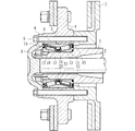
FIG. 1 is a longitudinal sectional view showing an embodiment of a drive wheel support device according to the present invention, FIG. 2 is a longitudinal sectional view showing a bearing for the wheel, and FIG. 4 is an enlarged view of a main part showing a modified example of the first seal ring of FIG. 3, FIG. 5 is an enlarged view of a main part showing another modified example of FIG. 3, and FIG. FIG. 7 is an enlarged view of a main part showing another modification of the first seal ring shown in FIG. 3, and FIG. 8 is another view of the first seal ring shown in FIG. FIG. 9 is an enlarged view of a main part showing a portion B of FIG. 2, FIG. 10 is an enlarged view of a main part showing a modified example of the second seal ring of FIG. 9, and FIG. FIG. 12 is an enlarged view of a main part showing another modification of the second seal ring of FIG. In the following description, the side closer to the outer side of the vehicle when assembled to the vehicle is referred to as the outer side (left side in FIG. 1), and the side closer to the center is referred to as the inner side (right side in FIG. 1).
この駆動輪支持装置は、車軸管1の中にデファレンシャル(図示せず)と連結された駆動軸2が挿通され、車軸管1の外径面に複列の円錐ころ軸受3が装着されている。この複列の円錐ころ軸受3により回転自在に支承されたハブ輪4が、ハブボルト5を介して駆動軸2のフランジ6に連結されている。複列の円錐ころ軸受3はハブ輪4に内嵌されると共に、車軸管1のアウター側の端部に外嵌され、その両端をフランジ6とブレーキロータ7により挟持された状態で固定ナット8によって締付固定されている。
In this drive wheel support device, a drive shaft 2 connected to a differential (not shown) is inserted into an axle tube 1, and a double row tapered
複列の円錐ころ軸受3は、図2に示すように、内周にそれぞれ外向きに開いたテーパ状の複列の外側転走面9a、9aが一体に形成された外輪9と、外周にこれら複列の外側転走面9a、9aに対向するテーパ状の内側転走面10aが形成された一対の内輪10、11と、両転走面間に保持器12を介して転動自在に収容された複列の円錐ころ13、13とを備えている。内輪10、11の内側転走面10aの大径側には円錐ころ13を案内するための大鍔部10bが形成されると共に、小径側には円錐ころ13の脱落を防止するための小鍔部10cが形成されている。そして、一対の内輪10、11の小径側端面が突き合された状態でセットされ、所謂背面合せタイプの複列の円錐ころ軸受を構成している。一対の内輪10、11は基本的に同一仕様であるが、内輪10、11の大径側の構成が異なる。
As shown in FIG. 2, the double-row tapered
外輪9と一対の内輪10、11との間に形成される環状空間の開口部にはシール14、15が装着され、シール14はデフオイルが軸受内部に侵入するのを防止し、シール15は、軸受内部に封入された潤滑グリースの外部への漏洩と、外部から雨水やダスト等が軸受内部に侵入するのを防止している。
アウター側のシール14は、外輪9の端部内周に圧入された芯金16と、この芯金16に加硫接着によって一体に接合されたシール部材17とからなる一体型シールで構成されている。シール部材17はACM(ポリアクリルゴム)やNBR(アクリロニトリル−ブタジエンゴム)等の合成ゴムからなり、内輪10の外径に摺接する二股状のラジアルリップ17a、17bを有している。芯金16は、オーステナイト系ステンレス鋼鈑(JIS規格のSUS304系等)、あるいは、防錆処理された冷間圧延鋼鈑(JIS規格のSPCC系等)からプレス加工にて断面が略L字状に形成されている。
The outer-
インナー側のシール15は、断面が略L字状に形成されて互いに対向配置された環状のシール板18とスリンガ19とからなる、所謂パックシールを構成している。シール板18は、外輪9の端部内周に圧入される芯金20と、この芯金20に一体に加硫接着されたシール部材21とからなる。芯金20は、オーステナイト系ステンレス鋼鈑(JIS規格のSUS304系等)、あるいは、防錆処理された冷間圧延鋼鈑(JIS規格のSPCC系等)からプレス加工にて断面が略L字状に形成されている。
The inner-
シール部材21はNBR等の合成ゴムからなり、径方向外方に傾斜して形成された一対のサイドリップ21a、21bと、このサイドリップ21bの内径側に軸受内方側に傾斜して形成されたグリースリップ21cとを有している。
The
スリンガ19は、オーステナイト系ステンレス鋼鈑(JIS規格のSUS304系等)、あるいは、防錆処理された冷間圧延鋼鈑(JIS規格のSPCC系等)からプレス加工にて断面が略L字状に形成され、内輪11の外径に圧入される円筒部19aと、この円筒部19aから径方向外方に延びる立板部19bとからなる。そして、シール部材21の一対のサイドリップ21a、21bが立板部19bに摺接されると共に、グリースリップ21cが円筒部19aに摺接されている。
外輪9と内輪10、11および円錐ころ13はSUJ2等の高炭素クロム鋼で形成され、ズブ焼入れによって芯部まで58〜64HRCの範囲に硬化処理されている。一対の内輪10、11の小径側端部には環状溝22、22が形成され、この環状溝22に連結環23が装着されている。この連結環23は、工具鋼やばね鋼等の鋼板をプレス加工により断面略コの字状に、全体として有端のリング状に形成され、表面に調質あるいは焼入れにより40〜55HRCの範囲に硬化処理が施されている。なお、ここでは、転動体として円錐ころを使用した複列円錐ころ軸受を例示したが、これに限らず転動体にボールを使用した複列アンギュラ玉軸受であっても良い。
The outer ring 9, the
ここで、本実施形態では、一対の内輪10、11の突合せ部外周面に環状凹部24が形成され、この環状凹部24に第1のシールリング25が装着されている。また、インナー側の内輪11の大径側端部には環状段部26が形成され、第2のシールリング27が装着されている。
Here, in the present embodiment, an
第1のシールリング25は、図3に拡大して示すように、芯金28と弾性部材29とで形成され、弾性部材29の内周には、突き合わせ部の両側に跨架して当接される2条の環状凸条29a、29bがそれぞれ形成されている。芯金28は、オーステナイト系ステンレス鋼鈑(JIS規格のSUS304系等)、あるいは、防錆処理された冷間圧延鋼鈑(JIS規格のSPCC系等)からプレス加工にて断面が略L字状に形成され、円筒部28aと、この円筒部28aから径方向外方に延びる鍔部28bとからなる。これにより、芯金28の剛性を確保して圧入時の変形を抑制すると共に、真円度等の所望の精度を確保することができる。なお、本実施例では、内径突起として2条の環状凸条を設けた例を示したが、2条の環状凸条に限られることはなく、複数の内径突起を設けても良い。
As shown in an enlarged view in FIG. 3, the
弾性部材29は、NBR等の合成ゴムからなり、加硫接着によって芯金28に一体に接合されている。環状凸条29a、29bのうちアウター側の環状凸条29aの幅寸法aは、インナー側の環状凸条29bの幅寸法bよりも大きく設定されている(a>b)。これにより、環状凸条29a、29bとの間に嵌合力の差が生じ位置決め精度を確保することができる。すなわち、予め第1のシールリング25をアウター側の内輪10の環状凹部24に圧入した後、第1のシールリング25の内径にインナー側の内輪11を圧入する時、嵌合力に差があるため、この圧入によって第1のシールリング25が位置ずれを起すことはない。つまり、嵌合力に差があることにより、組み付け時に内輪10の段付き部に、シールリング25の左端面が接触しない(図3)。シールリング25を内輪10に圧入する時に段付き部にシールリング25を突き当てて位置決めをするのではなく、内輪10の小径側端面とシールリング25右端面を位置決め治具で位置決めするため、シールリング25の損傷・変形を防止することができる。
The
また、第1のシールリング25における弾性部材29の内径側の厚さcが、一対の内輪10、11の環状凹部24の段差dよりも小さく設定されている(c<d)。これにより、第1のシールリング25の内径にインナー側の内輪11を圧入する時、第1のシールリング25と内輪11との間に芯違いがあって内輪11の端面によって第1のシールリング25を押すようなことがあっても、弾性部材29よりも剛性の高い芯金28部分が内輪10の環状凹部24に衝合するため大きな位置ずれを起すことはない。このような構成を採用することにより、一対の内輪10、11の突合せ部から軸受内部へデフオイルが浸入するのを確実に防止することができる。なお、弾性部材29の材質としては、NBR以外にも、例えば、耐熱性に優れたHNBR(水素化アクリロニトリル−ブタジエンゴム)、EPDM(エチレン・プロピレンゴム)等をはじめ、ACM、FKM(フッ素ゴム)、あるいはシリコンゴム等を例示することができる。特に、この種のデフオイルに触れる用途に対しては耐熱性、耐薬品性に優れたACM、FKM、EPM、シリコンゴムが好ましい。
Further, the thickness c on the inner diameter side of the
図4に示す第1のシールリング30は、図3の変形例を示す。この第1のシールリング30は、前述した第1のシールリング25と基本的には弾性部材の環状凸条の構成が異なるのみで、前述した実施形態と同一部品同一部位あるいは同一機能を有する部品や部位には同じ符号を付してその詳細な説明を省略する。
A
この第1のシールリング30は、芯金28と弾性部材31とで形成され、弾性部材31の内周には、突き合わせ部の両側に跨架して当接される2条の環状凸条31a、31bがそれぞれ形成されている。弾性部材31は、ACM等の合成ゴムからなり、加硫接着によって芯金28に一体に接合されている。環状凸条31a、31bのうちアウター側の環状凸条31aの突出量eは、インナー側の環状凸条31bの突出量fよりも大きく設定されている(e>f)。これにより、環状凸条31a、31bとの間にさらに嵌合力の差が生じ位置決め精度を一層確保することができる。
The
図5に示す実施形態は、図3の他の変形例で、基本的には内輪の環状凹部の構成が異なるのみで、前述した実施形態と同一部品同一部位あるいは同一機能を有する部品や部位には同じ符号を付してその詳細な説明を省略する。 The embodiment shown in FIG. 5 is another modification of FIG. 3 and basically differs only in the configuration of the annular recess of the inner ring. Are given the same reference numerals and their detailed description is omitted.
本実施形態では、一対の内輪10、11’の突合せ部外周面に環状凹部24、24’がそれぞれ形成され、この環状凹部24、24’に第1のシールリング25が装着されている。そして、環状凸条29a、29bの突出量は同じであるが、アウター側の内輪10における環状凹部24の外径D1oが、インナー側の内輪11’における環状凹部24’の外径D1iよりも径差g(半径)だけ大径に設定されている(D1o>D1i)。これにより、環状凸条29a、29bとの間にさらに嵌合力の差が生じ位置決め精度を一層確保することができる。
In the present embodiment,
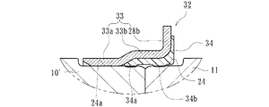
図6に示す実施形態は他の変形例である。一対の内輪10’、11の突合せ部外周面に環状凹部24a、24がそれぞれ形成され、この環状凹部24a、24に第1のシールリング32が装着されている。
The embodiment shown in FIG. 6 is another modification.
第1のシールリング32は、芯金33と弾性部材34とで形成され、弾性部材34の内周には、突き合わせ部の両側に跨架して当接される2条の環状凸条34a、34bがそれぞれ形成されている。芯金33は、オーステナイト系ステンレス鋼鈑(JIS規格のSUS304系等)、あるいは、防錆処理された冷間圧延鋼鈑(JIS規格のSPCC系等)からプレス加工にて断面が略L字状に形成され、内輪10’の環状凹部24aに圧入される第1の円筒部33aと、この第1の円筒部33aから僅かに大径に形成された第2の円筒部33bと、この第2の円筒部33bから径方向外方に延びる鍔部28bとからなる。これにより、芯金33の剛性を確保して圧入時の変形を抑制すると共に、真円度等の所望の精度を確保することができる。
The
一方、弾性部材34は、ACM等の合成ゴムからなり、加硫接着によって芯金33の第2の円筒部33bから鍔部28bに亙って一体に接合されている。環状凸条34a、34b幅寸法と突出量は同じに設定されている。本実施形態では、アウター側の内輪10’の環状凹部24aに芯金33が金属嵌合されているため、予め第1のシールリング32をアウター側の内輪10’の環状凹部24aに圧入した後、第1のシールリング32の内径にインナー側の内輪11を圧入する時の嵌合力に差が生じるため、この圧入によって第1のシールリング32が位置ずれを起すのを防止することができる。
On the other hand, the
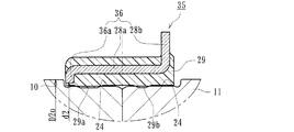
図7に示す第1のシールリング35は、図3の他の変形例を示す。この第1のシールリング35は、前述した第1のシールリング25と基本的には芯金の構成が異なるのみで、前述した実施形態と同一部品同一部位あるいは同一機能を有する部品や部位には同じ符号を付してその詳細な説明を省略する。
A
この第1のシールリング35は、芯金36と弾性部材29とで形成され、弾性部材29の内周には、突き合わせ部の両側に跨架して当接される2条の環状凸条29a、29bがそれぞれ形成されている。芯金36は、オーステナイト系ステンレス鋼鈑(JIS規格のSUS304系等)、あるいは、防錆処理された冷間圧延鋼鈑(JIS規格のSPCC系等)からプレス加工にて断面が略L字状に形成され、円筒部28aと、この円筒部28aから径方向外方に延びる鍔部28bと、円筒部28aから径方向内方に延びる鍔部36aからなる。そして、鍔部36aの内径d2が、内輪10の小端部側の外径D2oよりも小径に設定されている(d2<D2o)。
The
これにより、芯金36の剛性がさらに高くなり、圧入時の変形を抑制できることは無論のこと、第1のシールリング35の内径にインナー側の内輪11を圧入する時、第1のシールリング35と内輪11との間に芯違いがあって内輪11の端面によって第1のシールリング35を押すようなことがあっても、芯金36の鍔部36aが内輪10の環状凹部24に確実に衝合するため大きな位置ずれを起すことなく精度良く位置決め固定することができると共に、環状凹部24の段差を最小限に抑えることができる。なお、第1のシールリング35の内径にインナー側の内輪11を圧入する時、予め第1のシールリング35の内周にグリース、好ましくは軸受内部に充填されるグリースと同一のグリースを塗布することにより、挿入性を向上させることができると共に、圧入による位置ずれを防止することができる。
As a result, the rigidity of the cored
図8に示す第1のシールリング37は、図7の変形例を示す。この第1のシールリング37は、前述した第1のシールリング35と基本的には弾性部材の構成が異なるのみで、前述した実施形態と同一部品同一部位あるいは同一機能を有する部品や部位には同じ符号を付してその詳細な説明を省略する。
A
この第1のシールリング37の弾性部材38は芯金36に加硫接着により一体に接合され、弾性部材38の内周には、突き合わせ部の両側に跨架して当接される2条の環状凸条29a、29bと、これら環状凸条29a、29bにさらに環状凸条38a、38bがそれぞれ形成されている。これにより、第1のシールリング37の密封性が向上し、一対の内輪10、11の突合せ部から軸受内部へデフオイルが浸入するのを確実に防止することができる。
The
すなわち、この種の第1のシールリング37は、トラック等の軸重の大きい車両の車輪用軸受に使用されるため、通常の乗用車系のシールリングに比べて外径が大きい(φ70以上)。したがって、芯金36の形状を工夫して高剛性を図っても、圧入後の真円度等の精度を確保することは難しく、第1のシールリング37自体が楕円形状になる恐れがある。この場合、弾性部材38の環状凸条29a、29bで適正なシメシロを確保できなくなることが想定される。ここで、環状凸条29a、29bのシメシロを大きく設定することも考えられるが、これでは、シメシロが過多になる部分が発生し、圧入工程の作業性が悪くなるだけでなく、環状凸条29a、29bが損傷する恐れがある。本実施形態のように、環状凸条29a、29bにさらに小さな環状凸条38a、38bが形成されていることにより、こうした不具合を回避することができると共に、圧入後の第1のシールリング37の真円度が悪い場合であってもこれら小さな環状凸条38a、38bによって適正なシメシロを確保することができるため、所望の密封性を確保することができる。
That is, since this type of
次に、インナー側の内輪11の大径側端部に形成された環状段部26に装着された第2のシールリング27について説明する。この第2のシールリング27は、図9に拡大して示すように、芯金39と弾性部材40とで形成され、弾性部材40は車軸管1の肩部1aに当接されて、内輪11と車軸管1の間の僅かな隙間を遮断している。
Next, the
芯金39は、オーステナイト系ステンレス鋼鈑(JIS規格のSUS304系等)、あるいは、防錆処理された冷間圧延鋼鈑(JIS規格のSPCC系等)からプレス加工にて断面が略L字状に形成されている。一方、弾性部材40はACM等の合成ゴムからなり、加硫接着によって芯金39の外径部分を覆うように一体に接合され、円弧状に形成された肩部1aに所定のシメシロを介して当接するリップ40aを有している。この弾性部材40の外径d3は、環状段部26の内径D3iよりも僅かに小径に設定され(d3<D3i)、端部に環状の突起40bが形成されている。そして、この突起40bを弾性変形させた状態で環状段部26に装着されている。これにより、第2のシールリング27を環状段部26に圧入する際、弾性部材40が損傷するのを防止し、安定した気密性を確保することができる。
The
図10に示す第2のシールリング41は、図9の変形例で、基本的には弾性部材の一部の形状が異なるのみで、その他同一部品同一部位あるいは同一機能を有する部品や部位には同じ符号を付してその詳細な説明を省略する。
The
この第2のシールリング41は、芯金39と弾性部材42とで形成され、弾性部材42は、車軸管1の肩部1aに当接するリップ40aと外径部に突起40bを一体に有している。さらに弾性部材42の端部に環状の突起42aが軸方向に突出して形成され、環状段部26の壁面に弾性変形した状態で装着されている。外径部の突起40bは、圧入時に損傷するのを防止するために、その突出量h1が0.5mm以下に設定されている。また、端部の突起42aの突出量h2は、環状段部26のヌスミ部26aの幅L1から外径部の突起40bの幅L2の差よりも大きくなるように設定されている(h2≧L1−L2)。これにより、正確に位置決め固定ができると共に、軸受搬送時や組立時等に、第2のシールリング41がぐらつかず、信頼性を向上させることができる。
The
図11に示す第2のシールリング43は、図9の他の変形例で、芯金44と弾性部材45とで形成されている。芯金44は、オーステナイト系ステンレス鋼鈑(JIS規格のSUS304系等)、あるいは、防錆処理された冷間圧延鋼鈑(JIS規格のSPCC系等)からプレス加工にて断面が略L字状に形成され、環状段部26に圧入される円筒部44aと、この円筒部44aから径方向内方に延びる内径部44bとを有している。
A
弾性部材45は、車軸管1の肩部1aに当接されるリップ45aを一体に有すると共に、芯金44の円筒部44aの端部は縮径され、弾性部材45の一部が回り込むように加硫接着され、嵌合部45bが形成されている。この嵌合部45bと芯金44の円筒部44aによって、第2のシールリング43は、環状段部26に対して正確に位置決め固定ができ、気密性が向上すると共に、軸受搬送時や組立時等に、第2のシールリング43がぐらつかず、信頼性を向上させることができる。
The
図12に示す第2のシールリング46は、図9の他の変形例で、芯金47と弾性部材48とで形成されている。内輪11”の大径側端部には第1の環状段部49と、この第1の環状段部49よりも小径の第2の環状段部50が形成され、この第2の環状段部50に第2のシールリング46が装着されている。なお、図12において第2のシールリング46の芯金は複数回折り曲げられた形状となっている。
A
第2のシールリング46の芯金47は、オーステナイト系ステンレス鋼鈑(JIS規格のSUS304系等)、あるいは、防錆処理された冷間圧延鋼鈑(JIS規格のSPCC系等)からプレス加工にて断面が略クランク形状に形成され、外径円筒部47aと、この外径円筒部47aから径方向内方に延びる鍔部47bと、この鍔部47bから軸受内方側に延びる内径円筒部47cを有している。
The
一方、弾性部材48はACM等の合成ゴムからなり、加硫接着によって芯金47の全面を覆うように一体に接合され、円弧状に形成された肩部1aに所定のシメシロを介して当接するリップ48aと、第2の環状段部50に圧入される嵌合部48bを一体に有している。こうした構成を採用することにより、一層気密性が向上すると共に、軸受搬送時や組立時等に、第2のシールリング46がぐらつかず、信頼性を向上させることができる。
On the other hand, the
以上、本発明の実施の形態について説明を行ったが、本発明はこうした実施の形態に何等限定されるものではなく、あくまで例示であって、本発明の要旨を逸脱しない範囲内において、さらに種々なる形態で実施し得ることは勿論のことであり、本発明の範囲は、特許請求の範囲の記載によって示され、さらに特許請求の範囲に記載の均等の意味、および範囲内のすべての変更を含む。 The embodiment of the present invention has been described above, but the present invention is not limited to such an embodiment, and is merely an example, and various modifications can be made without departing from the scope of the present invention. Of course, the scope of the present invention is indicated by the description of the scope of claims, and further, the equivalent meanings described in the scope of claims and all modifications within the scope of the scope of the present invention are included. Including.
本発明に係る車輪用軸受装置は、駆動軸と車軸管の開口部に車輪用軸受が装着されたフルフローティングタイプの駆動輪側の車輪用軸受装置に適用できる。 The wheel bearing device according to the present invention can be applied to a full floating type wheel bearing device on the side of a driving wheel in which wheel bearings are mounted in openings of a driving shaft and an axle tube.
1・・・・・・・・・・・・・・・・・・・・・・・・・・・・・車軸管
1a・・・・・・・・・・・・・・・・・・・・・・・・・・・・肩部
2・・・・・・・・・・・・・・・・・・・・・・・・・・・・・駆動軸
3・・・・・・・・・・・・・・・・・・・・・・・・・・・・・複列の円錐ころ軸受
4・・・・・・・・・・・・・・・・・・・・・・・・・・・・・ハブ輪
5・・・・・・・・・・・・・・・・・・・・・・・・・・・・・ハブボルト
6・・・・・・・・・・・・・・・・・・・・・・・・・・・・・フランジ
7・・・・・・・・・・・・・・・・・・・・・・・・・・・・・ブレーキロータ
8・・・・・・・・・・・・・・・・・・・・・・・・・・・・・固定ナット
9・・・・・・・・・・・・・・・・・・・・・・・・・・・・・外輪
9a・・・・・・・・・・・・・・・・・・・・・・・・・・・・外側転走面
10、10’・・・・・・・・・・・・・・・・・・・・・・・・アウター側の内輪
11、11’、11”・・・・・・・・・・・・・・・・・・・・インナー側の内輪
10a・・・・・・・・・・・・・・・・・・・・・・・・・・・内側転走面
10b・・・・・・・・・・・・・・・・・・・・・・・・・・・大鍔部
10c・・・・・・・・・・・・・・・・・・・・・・・・・・・小鍔部
12・・・・・・・・・・・・・・・・・・・・・・・・・・・・保持器
13・・・・・・・・・・・・・・・・・・・・・・・・・・・・円錐ころ
14・・・・・・・・・・・・・・・・・・・・・・・・・・・・アウター側のシール
15・・・・・・・・・・・・・・・・・・・・・・・・・・・・インナー側のシール
16、20、28、33、36、39、44、47・・・・・・・芯金
17、21・・・・・・・・・・・・・・・・・・・・・・・・・シール部材
18・・・・・・・・・・・・・・・・・・・・・・・・・・・・シール板
19・・・・・・・・・・・・・・・・・・・・・・・・・・・・スリンガ
19a、28a、44a・・・・・・・・・・・・・・・・・・・円筒部
19b・・・・・・・・・・・・・・・・・・・・・・・・・・・立板部
21a、21b・・・・・・・・・・・・・・・・・・・・・・・サイドリップ
21c・・・・・・・・・・・・・・・・・・・・・・・・・・・グリースリップ
22・・・・・・・・・・・・・・・・・・・・・・・・・・・・環状溝
23・・・・・・・・・・・・・・・・・・・・・・・・・・・・連結環
24、24’、24a・・・・・・・・・・・・・・・・・・・・環状凹部
25、30、32、35、37・・・・・・・・・・・・・・・・第1のシールリング
26・・・・・・・・・・・・・・・・・・・・・・・・・・・・環状段部
26a・・・・・・・・・・・・・・・・・・・・・・・・・・・ヌスミ部
27、41、43、46・・・・・・・・・・・・・・・・・・・第2のシールリング
28b、36a、47b・・・・・・・・・・・・・・・・・・・鍔部
29、31、34、38、40、42、45、48・・・・・・・弾性部材
29a、29b、31a、31b、34a、34b、38a、38b・・環状凸条
33a・・・・・・・・・・・・・・・・・・・・・・・・・・・第1の円筒部
33b・・・・・・・・・・・・・・・・・・・・・・・・・・・第2の円筒部
40a、45a、48a・・・・・・・・・・・・・・・・・・・リップ
40b、42a・・・・・・・・・・・・・・・・・・・・・・・突起
44b・・・・・・・・・・・・・・・・・・・・・・・・・・・内径部
45b、48b・・・・・・・・・・・・・・・・・・・・・・・嵌合部
47a・・・・・・・・・・・・・・・・・・・・・・・・・・・外径円筒部
47c・・・・・・・・・・・・・・・・・・・・・・・・・・・内径円筒部
49・・・・・・・・・・・・・・・・・・・・・・・・・・・・第1の環状段部
50・・・・・・・・・・・・・・・・・・・・・・・・・・・・第2の環状段部
51・・・・・・・・・・・・・・・・・・・・・・・・・・・・車軸管
52・・・・・・・・・・・・・・・・・・・・・・・・・・・・駆動軸
53・・・・・・・・・・・・・・・・・・・・・・・・・・・・複列の円錐ころ軸受
54・・・・・・・・・・・・・・・・・・・・・・・・・・・・ハブ輪
55・・・・・・・・・・・・・・・・・・・・・・・・・・・・ハブボルト
56・・・・・・・・・・・・・・・・・・・・・・・・・・・・フランジ
57・・・・・・・・・・・・・・・・・・・・・・・・・・・・内輪
58・・・・・・・・・・・・・・・・・・・・・・・・・・・・連結環
59・・・・・・・・・・・・・・・・・・・・・・・・・・・・固定ナット
60・・・・・・・・・・・・・・・・・・・・・・・・・・・・外輪
61・・・・・・・・・・・・・・・・・・・・・・・・・・・・ブレーキロータ
62・・・・・・・・・・・・・・・・・・・・・・・・・・・・円錐ころ
63・・・・・・・・・・・・・・・・・・・・・・・・・・・・保持器
64、64’・・・・・・・・・・・・・・・・・・・・・・・・シール
65・・・・・・・・・・・・・・・・・・・・・・・・・・・・環状段部
66、69・・・・・・・・・・・・・・・・・・・・・・・・・シールリング
67・・・・・・・・・・・・・・・・・・・・・・・・・・・・肩
68・・・・・・・・・・・・・・・・・・・・・・・・・・・・環状凹部
69a・・・・・・・・・・・・・・・・・・・・・・・・・・・芯金
69b・・・・・・・・・・・・・・・・・・・・・・・・・・・弾性部材
70・・・・・・・・・・・・・・・・・・・・・・・・・・・・環状凸条
a、b・・・・・・・・・・・・・・・・・・・・・・・・・・・環状凸条の幅寸法
c・・・・・・・・・・・・・・・・・・・・・・・・・・・・・弾性部材の厚さ
d・・・・・・・・・・・・・・・・・・・・・・・・・・・・・環状凹部の段差
e、f・・・・・・・・・・・・・・・・・・・・・・・・・・・環状凸条の突出量
g・・・・・・・・・・・・・・・・・・・・・・・・・・・・・環状凹部の外径の径差
d2・・・・・・・・・・・・・・・・・・・・・・・・・・・・芯金の鍔部の内径
d3・・・・・・・・・・・・・・・・・・・・・・・・・・・・弾性部材の外径
D1i、D1o・・・・・・・・・・・・・・・・・・・・・・・環状凹部の外径
D2o・・・・・・・・・・・・・・・・・・・・・・・・・・・内輪の小端部側の外径
D3i・・・・・・・・・・・・・・・・・・・・・・・・・・・環状段部の内径
h1、h2・・・・・・・・・・・・・・・・・・・・・・・・・突起の突出量
L1・・・・・・・・・・・・・・・・・・・・・・・・・・・・ヌスミ部の幅
L2・・・・・・・・・・・・・・・・・・・・・・・・・・・・突起の幅
1 ... Axle tube 1a ...・ ・ ・ ・ ・ ・ ・ ・ ・ ・ ・ Shoulder 2 ・ ・ ・ ・ ・ ・ ・ ・ ・ ・ ・ ・ ・ ・ ・ ・ ・ ・ ・ ・ ・ ・ ・ ・ ・ ・
Claims (12)
この車軸管の外径段差部に嵌挿され、前記ハブ輪を回転自在に支持する複列の転がり軸受からなる車輪用軸受とを備えると共に、
この車輪用軸受が、内周に複列の外側転走面が一体に形成された外輪と、
外周に前記複列の外側転走面に対向する内側転走面が形成された一対の内輪と、
これら内輪と前記外輪の各転走面間に保持器を介して転動自在に収容された複列の転動体と、
前記外輪と内輪との間に形成される環状空間の開口部に装着されたシールとを備え、
前記一対の内輪の突合せ部外周面に環状凹部が形成され、この環状凹部に第1のシールリングが装着されると共に、
前記一対の内輪のうちインナー側の内輪の端部内周に環状段部が形成され、この環状段部に第2のシールリングが装着された駆動輪支持装置において、
前記第1のシールリングが、鋼鈑からプレス加工にて断面が略L字状に形成され、円筒部およびこの円筒部から径方向外方に延びる鍔部を有する芯金と、この芯金に加硫接着により一体に接合された合成ゴムからなる弾性部材とで構成されていることを特徴とする駆動輪支持装置。 A hub wheel integrally having a wheel mounting flange for mounting a wheel; an axle tube externally fitted to the drive shaft;
A wheel bearing comprising a double row rolling bearing that is fitted into the outer diameter step portion of the axle tube and rotatably supports the hub wheel,
This wheel bearing has an outer ring in which a double row outer rolling surface is integrally formed on the inner periphery,
A pair of inner rings formed on the outer periphery with an inner rolling surface facing the double row outer rolling surface;
A double row rolling element housed between the rolling surfaces of the inner ring and the outer ring via a cage;
A seal attached to an opening of an annular space formed between the outer ring and the inner ring,
An annular recess is formed on the outer peripheral surface of the butted portion of the pair of inner rings, and a first seal ring is attached to the annular recess,
In the drive wheel support device in which an annular step is formed on the inner periphery of the inner ring on the inner side of the pair of inner rings, and a second seal ring is attached to the annular step.
The first seal ring is formed by pressing a steel plate into a substantially L-shaped cross section, and has a cylindrical part and a core part having a cylindrical part extending radially outward from the cylindrical part. A drive wheel support device comprising: an elastic member made of synthetic rubber joined together by vulcanization adhesion.
Priority Applications (1)
| Application Number | Priority Date | Filing Date | Title |
|---|---|---|---|
| JP2008186758A JP5252489B2 (en) | 2008-07-18 | 2008-07-18 | Drive wheel support device |
Applications Claiming Priority (1)
| Application Number | Priority Date | Filing Date | Title |
|---|---|---|---|
| JP2008186758A JP5252489B2 (en) | 2008-07-18 | 2008-07-18 | Drive wheel support device |
Publications (2)
| Publication Number | Publication Date |
|---|---|
| JP2010025216A true JP2010025216A (en) | 2010-02-04 |
| JP5252489B2 JP5252489B2 (en) | 2013-07-31 |
Family
ID=41731246
Family Applications (1)
| Application Number | Title | Priority Date | Filing Date |
|---|---|---|---|
| JP2008186758A Active JP5252489B2 (en) | 2008-07-18 | 2008-07-18 | Drive wheel support device |
Country Status (1)
| Country | Link |
|---|---|
| JP (1) | JP5252489B2 (en) |
Cited By (9)
| Publication number | Priority date | Publication date | Assignee | Title |
|---|---|---|---|---|
| JP2011251649A (en) * | 2010-06-03 | 2011-12-15 | Ntn Corp | Bearing device for wheel |
| JP2014178006A (en) * | 2013-03-15 | 2014-09-25 | Ntn Corp | Bearing device with sealing device |
| JP2015016778A (en) * | 2013-07-11 | 2015-01-29 | Ntn株式会社 | Bearing device for wheel |
| WO2015092099A1 (en) * | 2013-12-19 | 2015-06-25 | Fersa Innova, S.L.U. | Sealing gasket |
| JP2015212567A (en) * | 2014-05-07 | 2015-11-26 | 日本精工株式会社 | Rolling bearing |
| JP2017020610A (en) * | 2015-07-14 | 2017-01-26 | 株式会社ジェイテクト | Bearing device for wheel |
| DE102015220151A1 (en) * | 2015-10-16 | 2017-04-20 | Aktiebolaget Skf | Bearing arrangement and seal |
| JP2018002148A (en) * | 2017-09-08 | 2018-01-11 | Ntn株式会社 | Bearing device for wheel |
| WO2021093914A1 (en) * | 2019-11-11 | 2021-05-20 | Schaeffler Technologies AG & Co. KG | Wheel bearing unit |
Citations (4)
| Publication number | Priority date | Publication date | Assignee | Title |
|---|---|---|---|---|
| JP2000104747A (en) * | 1998-07-29 | 2000-04-11 | Nsk Ltd | Capped rolling bearing |
| JP2001099172A (en) * | 1999-09-27 | 2001-04-10 | Ntn Corp | Drive wheel support device |
| JP2007187218A (en) * | 2006-01-12 | 2007-07-26 | Ntn Corp | Bearing device for wheel |
| JP2008075834A (en) * | 2006-09-25 | 2008-04-03 | Jtekt Corp | Rolling bearing device |
-
2008
- 2008-07-18 JP JP2008186758A patent/JP5252489B2/en active Active
Patent Citations (4)
| Publication number | Priority date | Publication date | Assignee | Title |
|---|---|---|---|---|
| JP2000104747A (en) * | 1998-07-29 | 2000-04-11 | Nsk Ltd | Capped rolling bearing |
| JP2001099172A (en) * | 1999-09-27 | 2001-04-10 | Ntn Corp | Drive wheel support device |
| JP2007187218A (en) * | 2006-01-12 | 2007-07-26 | Ntn Corp | Bearing device for wheel |
| JP2008075834A (en) * | 2006-09-25 | 2008-04-03 | Jtekt Corp | Rolling bearing device |
Cited By (11)
| Publication number | Priority date | Publication date | Assignee | Title |
|---|---|---|---|---|
| JP2011251649A (en) * | 2010-06-03 | 2011-12-15 | Ntn Corp | Bearing device for wheel |
| JP2014178006A (en) * | 2013-03-15 | 2014-09-25 | Ntn Corp | Bearing device with sealing device |
| JP2015016778A (en) * | 2013-07-11 | 2015-01-29 | Ntn株式会社 | Bearing device for wheel |
| WO2015092099A1 (en) * | 2013-12-19 | 2015-06-25 | Fersa Innova, S.L.U. | Sealing gasket |
| JP2015212567A (en) * | 2014-05-07 | 2015-11-26 | 日本精工株式会社 | Rolling bearing |
| JP2017020610A (en) * | 2015-07-14 | 2017-01-26 | 株式会社ジェイテクト | Bearing device for wheel |
| DE102015220151A1 (en) * | 2015-10-16 | 2017-04-20 | Aktiebolaget Skf | Bearing arrangement and seal |
| JP2018002148A (en) * | 2017-09-08 | 2018-01-11 | Ntn株式会社 | Bearing device for wheel |
| WO2021093914A1 (en) * | 2019-11-11 | 2021-05-20 | Schaeffler Technologies AG & Co. KG | Wheel bearing unit |
| CN114402144A (en) * | 2019-11-11 | 2022-04-26 | 舍弗勒技术股份两合公司 | Wheel bearing unit |
| US11965554B2 (en) | 2019-11-11 | 2024-04-23 | Schaeffler Technologies AG & Co. KG | Wheel bearing unit |
Also Published As
| Publication number | Publication date |
|---|---|
| JP5252489B2 (en) | 2013-07-31 |
Similar Documents
| Publication | Publication Date | Title |
|---|---|---|
| JP5252489B2 (en) | Drive wheel support device | |
| JP6275465B2 (en) | SEALING DEVICE AND WHEEL BEARING DEVICE HAVING THE SAME | |
| JP5469497B2 (en) | Wheel bearing device | |
| JP5560090B2 (en) | Wheel bearing device | |
| JP2012056411A (en) | Wheel bearing device | |
| JP6730786B2 (en) | Wheel bearing device | |
| JP2016186319A (en) | Sealing device and wheel bearing device having the same | |
| JP2015152030A (en) | Sealing device and vehicle bearing device with the same | |
| JP2011027130A (en) | Bearing device for wheel | |
| JP2008045673A (en) | Wheel bearing device | |
| JP2011148409A (en) | Bearing device for wheel | |
| JP2016003709A (en) | Wheel bearing device | |
| JP6235256B2 (en) | Wheel bearing device | |
| JP2009250297A (en) | Wheel bearing seal and wheel bearing device provided with the same | |
| JP2011069458A (en) | Bearing device for wheel | |
| JP2011251649A (en) | Bearing device for wheel | |
| JP4854324B2 (en) | Seal press-fitting method for wheel bearing device | |
| JP6629802B2 (en) | Wheel bearing device | |
| JP2012154373A (en) | Wheel bearing seal | |
| CN110446870B (en) | Bearing device for wheel | |
| JP6396681B2 (en) | Wheel bearing device | |
| JP2005226787A (en) | Sealing device for bearing | |
| JP6483460B2 (en) | SEALING DEVICE AND WHEEL BEARING DEVICE HAVING THE SAME | |
| JP2011080499A (en) | Wheel bearing device | |
| JP2013040664A (en) | Wheel bearing device |
Legal Events
| Date | Code | Title | Description |
|---|---|---|---|
| A621 | Written request for application examination |
Free format text: JAPANESE INTERMEDIATE CODE: A621 Effective date: 20110629 |
|
| A131 | Notification of reasons for refusal |
Free format text: JAPANESE INTERMEDIATE CODE: A131 Effective date: 20120523 |
|
| A977 | Report on retrieval |
Free format text: JAPANESE INTERMEDIATE CODE: A971007 Effective date: 20120524 |
|
| A521 | Request for written amendment filed |
Free format text: JAPANESE INTERMEDIATE CODE: A523 Effective date: 20120717 |
|
| A02 | Decision of refusal |
Free format text: JAPANESE INTERMEDIATE CODE: A02 Effective date: 20130111 |
|
| A521 | Request for written amendment filed |
Free format text: JAPANESE INTERMEDIATE CODE: A523 Effective date: 20130313 |
|
| A911 | Transfer to examiner for re-examination before appeal (zenchi) |
Free format text: JAPANESE INTERMEDIATE CODE: A911 Effective date: 20130321 |
|
| TRDD | Decision of grant or rejection written | ||
| A01 | Written decision to grant a patent or to grant a registration (utility model) |
Free format text: JAPANESE INTERMEDIATE CODE: A01 Effective date: 20130410 |
|
| A61 | First payment of annual fees (during grant procedure) |
Free format text: JAPANESE INTERMEDIATE CODE: A61 Effective date: 20130410 |
|
| R150 | Certificate of patent or registration of utility model |
Ref document number: 5252489 Country of ref document: JP Free format text: JAPANESE INTERMEDIATE CODE: R150 Free format text: JAPANESE INTERMEDIATE CODE: R150 |
|
| FPAY | Renewal fee payment (event date is renewal date of database) |
Free format text: PAYMENT UNTIL: 20160426 Year of fee payment: 3 |
|
| R250 | Receipt of annual fees |
Free format text: JAPANESE INTERMEDIATE CODE: R250 |
|
| R250 | Receipt of annual fees |
Free format text: JAPANESE INTERMEDIATE CODE: R250 |
|
| R250 | Receipt of annual fees |
Free format text: JAPANESE INTERMEDIATE CODE: R250 |
|
| R250 | Receipt of annual fees |
Free format text: JAPANESE INTERMEDIATE CODE: R250 |
|
| R250 | Receipt of annual fees |
Free format text: JAPANESE INTERMEDIATE CODE: R250 |
|
| R250 | Receipt of annual fees |
Free format text: JAPANESE INTERMEDIATE CODE: R250 |
|
| R250 | Receipt of annual fees |
Free format text: JAPANESE INTERMEDIATE CODE: R250 |
|
| R250 | Receipt of annual fees |
Free format text: JAPANESE INTERMEDIATE CODE: R250 |
|
| R250 | Receipt of annual fees |
Free format text: JAPANESE INTERMEDIATE CODE: R250 |