JP5560090B2 - Wheel bearing device - Google Patents
Wheel bearing device Download PDFInfo
- Publication number
- JP5560090B2 JP5560090B2 JP2010112824A JP2010112824A JP5560090B2 JP 5560090 B2 JP5560090 B2 JP 5560090B2 JP 2010112824 A JP2010112824 A JP 2010112824A JP 2010112824 A JP2010112824 A JP 2010112824A JP 5560090 B2 JP5560090 B2 JP 5560090B2
- Authority
- JP
- Japan
- Prior art keywords
- wheel
- axle tube
- annular groove
- diameter
- seal ring
- Prior art date
- Legal status (The legal status is an assumption and is not a legal conclusion. Google has not performed a legal analysis and makes no representation as to the accuracy of the status listed.)
- Expired - Fee Related
Links
Images


Classifications
-
- F—MECHANICAL ENGINEERING; LIGHTING; HEATING; WEAPONS; BLASTING
- F16—ENGINEERING ELEMENTS AND UNITS; GENERAL MEASURES FOR PRODUCING AND MAINTAINING EFFECTIVE FUNCTIONING OF MACHINES OR INSTALLATIONS; THERMAL INSULATION IN GENERAL
- F16C—SHAFTS; FLEXIBLE SHAFTS; ELEMENTS OR CRANKSHAFT MECHANISMS; ROTARY BODIES OTHER THAN GEARING ELEMENTS; BEARINGS
- F16C33/00—Parts of bearings; Special methods for making bearings or parts thereof
- F16C33/72—Sealings
- F16C33/76—Sealings of ball or roller bearings
- F16C33/78—Sealings of ball or roller bearings with a diaphragm, disc, or ring, with or without resilient members
- F16C33/7803—Sealings of ball or roller bearings with a diaphragm, disc, or ring, with or without resilient members suited for particular types of rolling bearings
- F16C33/7813—Sealings of ball or roller bearings with a diaphragm, disc, or ring, with or without resilient members suited for particular types of rolling bearings for tapered roller bearings
-
- B—PERFORMING OPERATIONS; TRANSPORTING
- B60—VEHICLES IN GENERAL
- B60B—VEHICLE WHEELS; CASTORS; AXLES FOR WHEELS OR CASTORS; INCREASING WHEEL ADHESION
- B60B27/00—Hubs
- B60B27/001—Hubs with roller-bearings
-
- B—PERFORMING OPERATIONS; TRANSPORTING
- B60—VEHICLES IN GENERAL
- B60B—VEHICLE WHEELS; CASTORS; AXLES FOR WHEELS OR CASTORS; INCREASING WHEEL ADHESION
- B60B27/00—Hubs
- B60B27/0073—Hubs characterised by sealing means
-
- B—PERFORMING OPERATIONS; TRANSPORTING
- B60—VEHICLES IN GENERAL
- B60B—VEHICLE WHEELS; CASTORS; AXLES FOR WHEELS OR CASTORS; INCREASING WHEEL ADHESION
- B60B27/00—Hubs
- B60B27/0078—Hubs characterised by the fixation of bearings
- B60B27/0084—Hubs characterised by the fixation of bearings caulking to fix inner race
-
- B—PERFORMING OPERATIONS; TRANSPORTING
- B60—VEHICLES IN GENERAL
- B60B—VEHICLE WHEELS; CASTORS; AXLES FOR WHEELS OR CASTORS; INCREASING WHEEL ADHESION
- B60B35/00—Axle units; Parts thereof ; Arrangements for lubrication of axles
- B60B35/12—Torque-transmitting axles
- B60B35/18—Arrangement of bearings
-
- F—MECHANICAL ENGINEERING; LIGHTING; HEATING; WEAPONS; BLASTING
- F16—ENGINEERING ELEMENTS AND UNITS; GENERAL MEASURES FOR PRODUCING AND MAINTAINING EFFECTIVE FUNCTIONING OF MACHINES OR INSTALLATIONS; THERMAL INSULATION IN GENERAL
- F16C—SHAFTS; FLEXIBLE SHAFTS; ELEMENTS OR CRANKSHAFT MECHANISMS; ROTARY BODIES OTHER THAN GEARING ELEMENTS; BEARINGS
- F16C19/00—Bearings with rolling contact, for exclusively rotary movement
- F16C19/22—Bearings with rolling contact, for exclusively rotary movement with bearing rollers essentially of the same size in one or more circular rows, e.g. needle bearings
- F16C19/34—Bearings with rolling contact, for exclusively rotary movement with bearing rollers essentially of the same size in one or more circular rows, e.g. needle bearings for both radial and axial load
- F16C19/38—Bearings with rolling contact, for exclusively rotary movement with bearing rollers essentially of the same size in one or more circular rows, e.g. needle bearings for both radial and axial load with two or more rows of rollers
- F16C19/383—Bearings with rolling contact, for exclusively rotary movement with bearing rollers essentially of the same size in one or more circular rows, e.g. needle bearings for both radial and axial load with two or more rows of rollers with tapered rollers, i.e. rollers having essentially the shape of a truncated cone
- F16C19/385—Bearings with rolling contact, for exclusively rotary movement with bearing rollers essentially of the same size in one or more circular rows, e.g. needle bearings for both radial and axial load with two or more rows of rollers with tapered rollers, i.e. rollers having essentially the shape of a truncated cone with two rows, i.e. double-row tapered roller bearings
- F16C19/386—Bearings with rolling contact, for exclusively rotary movement with bearing rollers essentially of the same size in one or more circular rows, e.g. needle bearings for both radial and axial load with two or more rows of rollers with tapered rollers, i.e. rollers having essentially the shape of a truncated cone with two rows, i.e. double-row tapered roller bearings in O-arrangement
-
- F—MECHANICAL ENGINEERING; LIGHTING; HEATING; WEAPONS; BLASTING
- F16—ENGINEERING ELEMENTS AND UNITS; GENERAL MEASURES FOR PRODUCING AND MAINTAINING EFFECTIVE FUNCTIONING OF MACHINES OR INSTALLATIONS; THERMAL INSULATION IN GENERAL
- F16C—SHAFTS; FLEXIBLE SHAFTS; ELEMENTS OR CRANKSHAFT MECHANISMS; ROTARY BODIES OTHER THAN GEARING ELEMENTS; BEARINGS
- F16C33/00—Parts of bearings; Special methods for making bearings or parts thereof
- F16C33/30—Parts of ball or roller bearings
- F16C33/58—Raceways; Race rings
- F16C33/583—Details of specific parts of races
- F16C33/586—Details of specific parts of races outside the space between the races, e.g. end faces or bore of inner ring
-
- F—MECHANICAL ENGINEERING; LIGHTING; HEATING; WEAPONS; BLASTING
- F16—ENGINEERING ELEMENTS AND UNITS; GENERAL MEASURES FOR PRODUCING AND MAINTAINING EFFECTIVE FUNCTIONING OF MACHINES OR INSTALLATIONS; THERMAL INSULATION IN GENERAL
- F16C—SHAFTS; FLEXIBLE SHAFTS; ELEMENTS OR CRANKSHAFT MECHANISMS; ROTARY BODIES OTHER THAN GEARING ELEMENTS; BEARINGS
- F16C33/00—Parts of bearings; Special methods for making bearings or parts thereof
- F16C33/72—Sealings
- F16C33/76—Sealings of ball or roller bearings
- F16C33/768—Sealings of ball or roller bearings between relatively stationary parts, i.e. static seals
-
- F—MECHANICAL ENGINEERING; LIGHTING; HEATING; WEAPONS; BLASTING
- F16—ENGINEERING ELEMENTS AND UNITS; GENERAL MEASURES FOR PRODUCING AND MAINTAINING EFFECTIVE FUNCTIONING OF MACHINES OR INSTALLATIONS; THERMAL INSULATION IN GENERAL
- F16C—SHAFTS; FLEXIBLE SHAFTS; ELEMENTS OR CRANKSHAFT MECHANISMS; ROTARY BODIES OTHER THAN GEARING ELEMENTS; BEARINGS
- F16C35/00—Rigid support of bearing units; Housings, e.g. caps, covers
- F16C35/04—Rigid support of bearing units; Housings, e.g. caps, covers in the case of ball or roller bearings
- F16C35/06—Mounting or dismounting of ball or roller bearings; Fixing them onto shaft or in housing
- F16C35/067—Fixing them in a housing
-
- B—PERFORMING OPERATIONS; TRANSPORTING
- B60—VEHICLES IN GENERAL
- B60B—VEHICLE WHEELS; CASTORS; AXLES FOR WHEELS OR CASTORS; INCREASING WHEEL ADHESION
- B60B2380/00—Bearings
- B60B2380/10—Type
- B60B2380/14—Roller bearings
-
- B—PERFORMING OPERATIONS; TRANSPORTING
- B60—VEHICLES IN GENERAL
- B60B—VEHICLE WHEELS; CASTORS; AXLES FOR WHEELS OR CASTORS; INCREASING WHEEL ADHESION
- B60B2380/00—Bearings
- B60B2380/70—Arrangements
- B60B2380/73—Double track
-
- B—PERFORMING OPERATIONS; TRANSPORTING
- B60—VEHICLES IN GENERAL
- B60B—VEHICLE WHEELS; CASTORS; AXLES FOR WHEELS OR CASTORS; INCREASING WHEEL ADHESION
- B60B2900/00—Purpose of invention
- B60B2900/20—Avoidance of
- B60B2900/211—Soiling
-
- B—PERFORMING OPERATIONS; TRANSPORTING
- B60—VEHICLES IN GENERAL
- B60B—VEHICLE WHEELS; CASTORS; AXLES FOR WHEELS OR CASTORS; INCREASING WHEEL ADHESION
- B60B2900/00—Purpose of invention
- B60B2900/50—Improvement of
- B60B2900/511—Sealing
- B60B2900/5112—Sealing against dust or dirt
-
- B—PERFORMING OPERATIONS; TRANSPORTING
- B60—VEHICLES IN GENERAL
- B60Y—INDEXING SCHEME RELATING TO ASPECTS CROSS-CUTTING VEHICLE TECHNOLOGY
- B60Y2200/00—Type of vehicle
- B60Y2200/10—Road Vehicles
- B60Y2200/11—Passenger cars; Automobiles
-
- F—MECHANICAL ENGINEERING; LIGHTING; HEATING; WEAPONS; BLASTING
- F16—ENGINEERING ELEMENTS AND UNITS; GENERAL MEASURES FOR PRODUCING AND MAINTAINING EFFECTIVE FUNCTIONING OF MACHINES OR INSTALLATIONS; THERMAL INSULATION IN GENERAL
- F16C—SHAFTS; FLEXIBLE SHAFTS; ELEMENTS OR CRANKSHAFT MECHANISMS; ROTARY BODIES OTHER THAN GEARING ELEMENTS; BEARINGS
- F16C2240/00—Specified values or numerical ranges of parameters; Relations between them
- F16C2240/40—Linear dimensions, e.g. length, radius, thickness, gap
- F16C2240/42—Groove sizes
-
- F—MECHANICAL ENGINEERING; LIGHTING; HEATING; WEAPONS; BLASTING
- F16—ENGINEERING ELEMENTS AND UNITS; GENERAL MEASURES FOR PRODUCING AND MAINTAINING EFFECTIVE FUNCTIONING OF MACHINES OR INSTALLATIONS; THERMAL INSULATION IN GENERAL
- F16C—SHAFTS; FLEXIBLE SHAFTS; ELEMENTS OR CRANKSHAFT MECHANISMS; ROTARY BODIES OTHER THAN GEARING ELEMENTS; BEARINGS
- F16C2326/00—Articles relating to transporting
- F16C2326/01—Parts of vehicles in general
- F16C2326/02—Wheel hubs or castors
Description
本発明は、自動車等の車輪を懸架装置に対して回転自在に支承する車輪用軸受装置、特に、駆動輪を複列の転がり軸受で支承するセミフローティングタイプの車輪用軸受装置に関するものである。 The present invention relates to a wheel bearing device that rotatably supports a wheel of an automobile or the like with respect to a suspension device, and more particularly to a semi-floating type wheel bearing device in which a driving wheel is supported by a double row rolling bearing.
トラック等のようにフレーム構造の車体を有する自動車では、駆動輪のアクスル構造として、従来フルフローティングタイプを採用するものが多い。また、最近の駆動輪の支持構造には、組立性の向上、軽量・コンパクト化等を狙って、複列の転がり軸受をユニット化した構造が多く採用されるようになっている。その従来構造の一例として、図6に示すようなセミフローティングタイプの車輪用軸受装置が知られている。 Many automobiles having a frame-structured body such as a truck adopt a conventional full floating type as an axle structure of a drive wheel. Also, recent drive wheel support structures are often adopted as a structure in which double row rolling bearings are unitized for the purpose of improving assemblability and reducing weight and size. As an example of the conventional structure, a semi-floating type wheel bearing device as shown in FIG. 6 is known.
この車輪用軸受装置は、軽量・コンパクト化を図ると共に、雨水やダスト等の侵入とデフオイルの漏れを防止したもので、ハブ輪51と複列の転がり軸受52とがユニット化して構成され、駆動軸D/Sに連結されている。複列の転がり軸受52は、内方部材53と外方部材54、および両部材53、54間に転動自在に収容された複列の円錐ころ55、55とを備えている。ハブ輪51は、外周の一端部に車輪WおよびブレーキロータBを取り付けるための車輪取付フランジ56を一体に有し、この車輪取付フランジ56から軸方向に延びる小径段部57が形成されている。また、内周には駆動軸D/Sがトルク伝達可能に内嵌されるようにセレーション58が形成されている。
This wheel bearing device is light and compact, and prevents rainwater, dust, etc. and diff oil from leaking. The
一方、複列の転がり軸受52は、内周に複列のテーパ状の外側転走面54a、54aが形成され、車軸管Hに固定される車体取付フランジ54bが外周に形成された外方部材54と、この外方部材54に内挿され、外周に前記複列の外側転走面54a、54aに対向するテーパ状の内側転走面60aが形成された一対の内輪60、60と、両転走面54a、60a間に転動自在に収容された複列の円錐ころ55、55とを有している。ハブ輪51の外周に形成された小径段部57には一対の内輪60、60が圧入され、小径段部57の端部を径方向外方に塑性変形させて形成した加締部59により、ハブ輪51に対して内輪60が軸方向へ抜けるのを防止している。そして、一対の内輪60、60の正面側端面が突き合された状態でセットされ、所謂背面合せタイプの複列の円錐ころ軸受を構成している。
On the other hand, the double-
ここで、ハブ輪51の開口部にキャップ61が圧入されている。このキャップ61は、オーステナイト系ステンレス鋼鈑(JIS規格のSUS304系等)、あるいは、防錆処理された冷間圧延鋼鈑(JIS規格のSPCC系等)をプレス加工にて断面略コの字形に形成された鋼板製の芯金61aと、この芯金61aの少なくとも嵌合部に加硫接着等により接合されたゴム等の弾性部材61bとからなる。そして、この弾性部材61bが嵌合面に弾性変形して入り込み、液密に内部を密封している。これにより、デフオイルの外部への流出と、外部から雨水やダスト等が駆動軸内に侵入してデフオイル内に混入するのを完全に防止することができると共に、車両運転時、ハブ輪51に繰返しモーメント荷重が負荷され弾性変形したとしても、このキャップ61がハブ輪51の弾性変形の影響を殆ど受けない(例えば、特許文献1参照。)。
Here, a
然しながら、このような従来の車輪用軸受装置では、車軸管Hと複列の転がり軸受52とのすきまを通して外部から雨水やダスト等が侵入する恐れがあると共に、デフオイルが外部に漏洩する恐れがある。この場合、雨水やダスト等がデフオイルに混入すると共に、漏洩したデフオイルが周辺を汚染するだけでなく、ブレーキロータBに飛散して制動不具合が発生する可能性がある。 However, in such a conventional wheel bearing device, rainwater or dust may enter from the outside through the clearance between the axle tube H and the double row rolling bearing 52, and the differential oil may leak to the outside. . In this case, rainwater, dust, and the like are mixed in the differential oil, and the leaked differential oil not only contaminates the surroundings but also may scatter to the brake rotor B and cause a braking failure.
本発明は、このような従来の問題に鑑みてなされたもので、雨水やダスト等の侵入とデフオイルの漏れを防止して封止効果を高め、長期間に亘って信頼性を確保した車輪用軸受装置を提供することを目的とする。 The present invention has been made in view of such conventional problems, and prevents the intrusion of rainwater, dust, etc. and the leakage of differential oil to enhance the sealing effect and ensure reliability over a long period of time. An object is to provide a bearing device.
係る目的を達成すべく、本発明のうち請求項1に記載の発明は、デファレンシャルと連結する駆動軸を内部に挿通して車体の下面に支持された車軸管と、前記駆動軸に結合され、車輪を取り付けるための車輪取付フランジを一体に有し、外周に軸方向に延びる円筒状の小径段部が形成されたハブ輪、およびこのハブ輪の小径段部と前記車軸管の開口部との間に嵌合され、前記車輪を回転自在に支承する車輪用軸受とを備え、この車輪用軸受が、外周に前記車軸管に取り付けられるための車体取付フランジと、インナー側の端部に前記車軸管に内嵌されるパイロット部を一体に有し、内周に複列の外側転走面が一体に形成された外方部材と、前記ハブ輪の小径段部に圧入され、前記複列の外側転走面に対向する内側転走面が形成された少なくとも一つの内輪とからなる内方部材と、この内方部材と前記外方部材の両転走面間に保持器を介して転動自在に収容された複列の転動体と、前記外方部材と内方部材との間に形成される環状空間の開口部に装着されたシールとを備えた車輪用軸受装置において、前記外方部材のパイロット部が、前記車体取付フランジから軸方向に延びる円筒部と、この円筒部からインナー側の端面に向って漸次縮径するテーパ部とで構成され、前記車軸管の嵌合部が前記外方部材のパイロット部の形状に対応して形成されると共に、前記外方部材のパイロット部のテーパ部に環状溝が形成され、この環状溝に合成ゴムからなるシールリングが装着されて前記車軸管に弾性接触され、当該シールリングの装着後の外径が、前記車軸管の円筒部の内径よりも小径に設定されて前記外方部材と車軸管との嵌合部の僅かな隙間が遮断されている。
In order to achieve such an object, the invention according to
このように、デファレンシャルと連結する駆動軸を内部に挿通して車体の下面に支持された車軸管と、車輪取付フランジを一体に有するハブ輪と、このハブ輪と車軸管の開口部との間に嵌合された複列の転がり軸受からなる車輪用軸受とを備えたセミフローティングタイプの車輪用軸受装置において、車軸管に内嵌される前記外方部材のパイロット部が、車体取付フランジから軸方向に延びる円筒部と、この円筒部からインナー側の端面に向って漸次縮径するテーパ部とで構成され、車軸管の嵌合部が外方部材のパイロット部の形状に対応して形成されると共に、外方部材のパイロット部のテーパ部に環状溝が形成され、この環状溝に合成ゴムからなるシールリングが装着されて車軸管に弾性接触され、当該シールリングの装着後の外径が、車軸管の円筒部の内径よりも小径に設定されて外方部材と車軸管との嵌合部の僅かな隙間が遮断されているので、軸受部の車軸管への組立が容易になり、組立作業が簡素化されると共に、雨水やダスト等の侵入とデフオイルの漏れを防止して封止効果を高め、長期間に亘って信頼性を確保した車輪用軸受装置を提供することができる。 As described above, the axle tube that is inserted into the drive shaft connected to the differential and is supported on the lower surface of the vehicle body, the hub wheel integrally including the wheel mounting flange, and the opening between the hub wheel and the opening of the axle tube. In a semi-floating type wheel bearing device including a wheel bearing composed of a double row rolling bearing fitted to the vehicle body, the pilot portion of the outer member fitted into the axle tube is pivoted from the vehicle body mounting flange. A cylindrical portion that extends in the direction and a tapered portion that gradually decreases in diameter from the cylindrical portion toward the end surface on the inner side, and the fitting portion of the axle tube is formed corresponding to the shape of the pilot portion of the outer member. Rutotomoni, an annular groove is formed in the tapered portion of the pilot portion of the outer member, the annular groove made of synthetic rubber sealing ring is mounted is elastically contacted to the axle tube, the outer diameter after mounting of the seal ring , Since a slight gap between the fitting portion between than the inner diameter of the cylindrical portion of the shaft tube is set in the small-diameter outer member and the axle tube is blocked, it becomes easy assembly into the axle tube of the bearing part, the assembly It is possible to provide a wheel bearing device in which the work is simplified and the sealing effect is enhanced by preventing intrusion of rainwater, dust, and the like and leakage of differential oil, and the reliability is ensured for a long period of time.
また、請求項2に記載の発明のように、前記シールリング単体での内径が、前記環状溝の溝底径よりも小径に設定されていれば、シールリングが装着された時にシメシロを有することになり、車軸管に軸受部を組み立てる際に、シールリングが撓んで車軸管に噛み込むのを防止することができる。 Further, as in the second aspect of the present invention, if the inner diameter of the seal ring alone is set smaller than the groove bottom diameter of the annular groove, the seal ring has a shimiro when the seal ring is mounted. Thus, when the bearing portion is assembled to the axle tube, the seal ring can be prevented from being bent and biting into the axle tube.
また、請求項3に記載の発明のように、前記外方部材の複列の外側転走面に高周波焼入れにより所定の硬化層が形成され、この硬化層の有効硬化層深さが2〜4.5mmの範囲に設定されると共に、前記環状溝と外側転走面との最短距離が4.5mm以上になるように設定されていれば、環状溝が焼入れによる熱影響を受けず、熱処理変形が防止できると共に、焼き抜け等で強度が低下するのを防止でき、信頼性を向上させることができる。 Further, as in the invention according to claim 3 , a predetermined hardened layer is formed by induction hardening on the outer raceway of the double row of the outer member, and the effective hardened layer depth of this hardened layer is 2-4. If the shortest distance between the annular groove and the outer rolling surface is set to 4.5 mm or more, the annular groove is not affected by heat due to quenching and heat treatment deformation is set. In addition, the strength can be prevented from being lowered due to burnout or the like, and the reliability can be improved.
また、請求項4に記載の発明のように、前記環状溝が断面略矩形状に形成され、当該環状溝の隅Rのうち前記外側転走面に近い側の隅Rが遠い側の隅Rよりも大きくなるように設定されていれば、同じ隅Rとした場合よりも実質的に外側転走面からの距離が大きくなるため、熱処理変形に対して有利となると共に、繰り返し曲げ荷重等が負荷された際の強度が高くなり、耐久性を向上させることができる。 According to a fourth aspect of the present invention, the annular groove is formed in a substantially rectangular cross section, and the corner R on the side closer to the outer rolling surface of the corner R of the annular groove is the far corner R. If it is set to be larger than the same corner R, the distance from the outer rolling surface is substantially larger than that in the case of the same corner R, which is advantageous for heat treatment deformation and repeated bending load and the like. The strength when loaded is increased, and the durability can be improved.
また、請求項5に記載の発明のように、前記環状溝が断面略半円形に形成され、溝底部の形状が単一の曲率半径で構成されていれば、焼入れによる熱影響を受け難く、また、切欠き効果による強度低下を抑制することができる。
Further, as in the invention according to
また、請求項6に記載の発明のように、前記シールリングのゴム物性値の圧縮永久歪が120℃×70時間で40%以下、TR10値(伸長率50%)が−20℃以下に設定されていれば、低温領域でも歪みの回復性が良好となり、所望の封止効果を維持することができる。
Further, as in the invention described in
また、請求項7に記載の発明のように、前記シールリングの色相が暖系色に設定されていれば、組立時のシールリングの装着忘れや装着確認の際の見逃しを防止することができ、組立作業の簡素化ができる。
Further, if the color of the seal ring is set to a warm color as in the invention described in
また、請求項8に記載の発明のように、前記シールリングに予め軸受内部に封入されるグリースと同一のグリースが塗布され、このグリースが表面に付着した状態で装着されていれば、シールリングの装着性が向上すると共に、組立の際にシールリングが車軸管に接触しても撓むことなくスムーズに車軸管に軸受部を嵌合させることができる。
Further, as in the invention described in
本発明に係る車輪用軸受装置は、デファレンシャルと連結する駆動軸を内部に挿通して車体の下面に支持された車軸管と、前記駆動軸に結合され、車輪を取り付けるための車輪取付フランジを一体に有し、外周に軸方向に延びる円筒状の小径段部が形成されたハブ輪、およびこのハブ輪の小径段部と前記車軸管の開口部との間に嵌合され、前記車輪を回転自在に支承する車輪用軸受とを備え、この車輪用軸受が、外周に前記車軸管に取り付けられるための車体取付フランジと、インナー側の端部に前記車軸管に内嵌されるパイロット部を一体に有し、内周に複列の外側転走面が一体に形成された外方部材と、前記ハブ輪の小径段部に圧入され、前記複列の外側転走面に対向する内側転走面が形成された少なくとも一つの内輪とからなる内方部材と、この内方部材と前記外方部材の両転走面間に保持器を介して転動自在に収容された複列の転動体と、前記外方部材と内方部材との間に形成される環状空間の開口部に装着されたシールとを備えた車輪用軸受装置において、前記外方部材のパイロット部が、前記車体取付フランジから軸方向に延びる円筒部と、この円筒部からインナー側の端面に向って漸次縮径するテーパ部とで構成され、前記車軸管の嵌合部が前記外方部材のパイロット部の形状に対応して形成されると共に、前記外方部材のパイロット部のテーパ部に環状溝が形成され、この環状溝に合成ゴムからなるシールリングが装着されて前記車軸管に弾性接触され、当該シールリングの装着後の外径が、前記車軸管の円筒部の内径よりも小径に設定されて前記外方部材と車軸管との嵌合部の僅かな隙間が遮断されているので、軸受部の車軸管への組立が容易になり、組立作業が簡素化されると共に、雨水やダスト等の侵入とデフオイルの漏れを防止して封止効果を高め、長期間に亘って信頼性を確保した車輪用軸受装置を提供することができる。 A wheel bearing device according to the present invention integrally includes an axle tube that is inserted into a drive shaft connected to a differential and supported on the lower surface of a vehicle body, and a wheel mounting flange that is coupled to the drive shaft and attaches a wheel. A hub wheel having a cylindrical small-diameter stepped portion extending in the axial direction on the outer periphery, and fitted between the small-diameter stepped portion of the hub wheel and the opening of the axle tube to rotate the wheel. A wheel bearing that is freely supported, and this wheel bearing is integrally formed with a vehicle body mounting flange on the outer periphery for mounting to the axle tube and a pilot portion that is fitted inside the axle tube at the inner end. An outer member in which a double row outer rolling surface is integrally formed on the inner periphery, and an inner rolling that is press-fitted into a small diameter step portion of the hub wheel and faces the outer rolling surface of the double row An inward portion comprising at least one inner ring formed with a surface And between the outer member and the inner member, and a double row rolling element accommodated between the rolling surfaces of the inner member and the outer member via a cage. In the wheel bearing device including a seal mounted in an opening of the annular space, a pilot portion of the outer member includes a cylindrical portion extending in an axial direction from the vehicle body mounting flange, and an inner side from the cylindrical portion. And a fitting portion of the axle tube corresponding to the shape of the pilot portion of the outer member, and the pilot portion of the outer member . An annular groove is formed in the tapered portion, and a seal ring made of synthetic rubber is attached to the annular groove and elastically contacted with the axle tube, and the outer diameter after attachment of the seal ring is the inner diameter of the cylindrical portion of the axle tube. the outer member and the axle is set smaller in diameter than As a result, the assembly of the bearing part to the axle tube is simplified, the assembly work is simplified, and intrusion of rainwater, dust, etc. and diff oil leakage are prevented. Thus, it is possible to provide a wheel bearing device that enhances the sealing effect and ensures reliability over a long period of time.
デファレンシャルと連結する駆動軸を内部に挿通して車体の下面に支持された車軸管と、前記駆動軸にセレーションを介して結合され、車輪を取り付けるための車輪取付フランジを一体に有し、外周に軸方向に延びる小径段部が形成されたハブ輪と、このハブ輪の小径段部と前記車軸管の開口部との間に嵌合され、前記車輪を回転自在に支承する車輪用軸受とを備え、この車輪用軸受が、外周に前記車軸管に取り付けられるための車体取付フランジと、インナー側の端部に前記車軸管に内嵌されるパイロット部を一体に有し、内周に複列の外側転走面が一体に形成された外方部材と、外周に前記複列の外側転走面に対向する内側転走面が形成された一対の内輪と、これら一対の内輪と前記外方部材の両転走面間に保持器を介して転動自在に収容された複列の転動体と、前記外方部材と一対の内輪との間に形成される環状空間の開口部に装着されたシールとを備え、前記ハブ輪の小径段部に前記車輪用軸受の内輪が嵌合され、当該小径段部の端部を径方向外方に塑性変形させて形成した加締部により前記内輪が前記ハブ輪に対して軸方向に固定されたセミフローティングタイプの車輪用軸受装置において、前記外方部材のパイロット部が、前記車体取付フランジから軸方向に延びる円筒部と、この円筒部からインナー側の端面に向って漸次縮径するテーパ部とで構成され、前記車軸管の嵌合部が前記外方部材のパイロット部の形状に対応して形成され、前記パイロット部のテーパ部に断面略矩形状の環状溝が形成され、この環状溝に合成ゴムからなるシールリングが装着されると共に、当該シールリングの装着後の外径が前記車軸管の円筒部の内径よりも小径に設定されて前記車軸管に弾性接触され、前記外方部材と車軸管との嵌合部の僅かな隙間が遮断されている。 An axle tube that is inserted into the drive shaft connected to the differential and is supported on the lower surface of the vehicle body, and a wheel mounting flange that is connected to the drive shaft via serrations and is attached to the outer periphery. A hub wheel having a small-diameter step portion extending in the axial direction, and a wheel bearing that is fitted between the small-diameter step portion of the hub wheel and the opening of the axle tube and rotatably supports the wheel. This wheel bearing has a vehicle body mounting flange for mounting to the axle tube on the outer periphery, and a pilot portion fitted into the axle tube on the inner side end portion, and a double row on the inner periphery. An outer member formed integrally with the outer rolling surface, a pair of inner rings formed with an inner rolling surface facing the outer rolling surface of the double row on the outer periphery, the pair of inner rings and the outer Rollable between the rolling surfaces of the member via a cage. A double row rolling element, and a seal attached to an opening of an annular space formed between the outer member and the pair of inner rings, and the wheel bearing at the small diameter step portion of the hub ring. A semi-floating type wheel in which the inner ring is axially fixed to the hub ring by a crimped portion formed by fitting an inner ring of the inner ring and plastically deforming the end portion of the small-diameter stepped portion radially outward. In the above bearing device, the pilot portion of the outer member includes a cylindrical portion that extends in the axial direction from the vehicle body mounting flange, and a tapered portion that gradually decreases in diameter from the cylindrical portion toward the inner end surface, A fitting portion of the axle tube is formed corresponding to the shape of the pilot portion of the outer member, an annular groove having a substantially rectangular cross section is formed in the tapered portion of the pilot portion, and a seal made of synthetic rubber is formed in the annular groove As the ring is attached The outer diameter after installation of the seal ring is set to be smaller than the inner diameter of the cylindrical portion of the axle tube and is in elastic contact with the axle tube, so that there is a slight gap between the fitting portion between the outer member and the axle tube. Blocked.
以下、本発明の実施の形態を図面に基づいて詳細に説明する。
図1は、本発明に係る車輪用軸受装置の一実施形態を示す足回り周辺の縦断面図、図2は、図1の車輪用軸受装置を示す縦断面図、図3(a)は、図2の要部拡大図、(b)は、(a)の部分拡大図、図4(a)は、図3(a)の変形例を示す要部拡大図、(b)は、(a)のシールリング単体を示す断面図、図5(a)は、図4の部分拡大図、(b)は(a)の変形例を示す部分拡大図である。なお、以下の説明では、車両に組み付けた状態で車両の外側寄りとなる側をアウター側(図1の左側)、中央寄り側をインナー側(図1の右側)という。
Hereinafter, embodiments of the present invention will be described in detail with reference to the drawings.
FIG. 1 is a longitudinal sectional view around the undercarriage showing an embodiment of a wheel bearing device according to the present invention, FIG. 2 is a longitudinal sectional view showing the wheel bearing device of FIG. 1, and FIG. 2B is an enlarged view of a portion of FIG. 2A, FIG. 4A is an enlarged view of a relevant portion showing a modification of FIG. 3A, and FIG. FIG. 5A is a partially enlarged view of FIG. 4 and FIG. 5B is a partially enlarged view showing a modification of FIG. 4A. In the following description, the side closer to the outer side of the vehicle when assembled to the vehicle is referred to as the outer side (left side in FIG. 1), and the side closer to the center is referred to as the inner side (right side in FIG. 1).
このセミフローティングタイプの車輪用軸受装置は、ハブ輪1と複列の転がり軸受2とがユニット化して構成され、駆動軸D/Sに連結されている。複列の転がり軸受2は、内方部材3と外方部材4、および両部材3、4間に転動自在に収容された複列の転動体(円錐ころ)5、5とを備えている。ここで、内方部材3は、ハブ輪1と、このハブ輪1に圧入された一対の内輪10、10とを指す。
In this semi-floating type wheel bearing device, a
ハブ輪1は、アウター側の端部に車輪WおよびブレーキロータBを取り付けるための車輪取付フランジ6を一体に有し、外周にこの車輪取付フランジ6から軸方向に延びる円筒状の小径段部7と、内周にセレーション(またはスプライン)8が形成されている。そして、駆動軸D/Sがハブ輪1にセレーション8を介して嵌挿されハブ輪1と駆動軸D/Sがトルク伝達自在に、かつ着脱自在に結合されている。
The
一方、複列の転がり軸受2は、図2に示すように、内周に複列のテーパ状の外側転走面4a、4aが一体に形成され、外周に車軸管14に固定されるための車体取付フランジ4bが一体に形成された外方部材4と、この外方部材4に内挿され、外周に前記複列の外側転走面4a、4aに対向するテーパ状の内側転走面10aが形成された一対の内輪10、10と、両転走面4a、10a間に収容された複列の転動体5、5と、これら複列の転動体5、5を転動自在に保持する保持器11とを備えている。
On the other hand, as shown in FIG. 2, the double-
一対の内輪10、10には内側転走面10aの大径側に転動体5を案内するための大鍔10bと、小径側に転動体5の脱落を防止するための小鍔10cが形成されている。そして、一対の内輪10、10の正面側端面が突き合された状態でセットされ、所謂背面合せタイプの複列の円錐ころ軸受を構成している。
The pair of
また、外方部材4と内輪10との間に形成される環状空間の開口部にはシール12、12が装着され、軸受内部に封入された潤滑グリースの外部への漏洩と、外部から雨水やダスト等が軸受内部に侵入するのを防止している。さらに、インナー側のシール12においては、ハブ輪1のセレーション8を通してデフオイルが軸受内部に浸入するのも防止している。
Further, seals 12 and 12 are attached to the opening of the annular space formed between the outer member 4 and the
ここで、ハブ輪1の小径段部7に一対の内輪10、10が所定のシメシロを介して圧入され、小径段部7の端部を径方向外方に塑性変形させて形成した加締部13により、所定の軸受予圧が付与された状態で、ハブ輪1に対して内輪10、10が軸方向に固定されている。本実施形態では、このような第2世代のセルフリテイン構造を採用することにより、従来のように内輪をナット等で強固に緊締して予圧量を管理する必要がないため、車両への組込性を簡便にすることができ、長期間その予圧量を維持することができると共に、部品点数を大幅に削減でき、組込性の向上と相俟って低コスト化と軽量・コンパクト化を達成することができる。
Here, a pair of
ハブ輪1はS53C等の炭素0.40〜0.80wt%を含む中高炭素鋼で形成され、複列の転がり軸受2が衝合される肩部1aから小径段部7に亙り高周波焼入れによって表面硬さを50〜64HRCの範囲に硬化処理されている(図中クロスハッチングにて示す)。なお、加締部13は、鍛造後の素材表面硬さ25HRC以下の未焼入れ部としている。これにより、耐久性が向上すると共に、加締部13を塑性変形する時の加工性が向上し、微小クラック等を防止してその品質の信頼性が向上する。
The
また、外方部材4は、ハブ輪1と同様、S53C等の炭素0.40〜0.80wt%を含む中高炭素鋼で形成され、少なくとも複列の外側転走面4a、4aが高周波焼入れによって表面硬さを58〜64HRCの範囲に硬化処理されている。一方、内輪10および転動体5はSUJ2等の高炭素クロム軸受鋼からなり、ズブ焼入れにより芯部まで60〜64HRCの範囲で硬化処理されている。なお、ここでは、転動体5、5を円錐ころとした複列円錐ころ軸受を例示したが、これに限らず転動体にボールを使用した複列アンギュラ玉軸受であっても良い。また、ハブ輪1の小径段部7に一対の内輪10、10が圧入固定された第2世代構造で構成された車輪用軸受装置を例示したが、これに限らず、図示はしないが、ハブ輪の外周に直接内側転走面が形成された第3世代構造で構成されたものでも良い。
Further, the outer member 4 is formed of medium and high carbon steel containing carbon of 0.40 to 0.80 wt% such as S53C, similar to the
本実施形態では、ハブ輪1のアウター側端部の開口部にキャップ9が圧入されている。このキャップ9は、オーステナイト系ステンレス鋼鈑(JIS規格のSUS304系等)、あるいは、防錆処理された冷間圧延鋼鈑(JIS規格のSPCC系等)をプレス加工にて断面略コの字形に形成された鋼板製の芯金9aと、この芯金9aの少なくとも嵌合部に加硫接着により接合された合成ゴム等の弾性部材9bとからなる。そして、この弾性部材9bが嵌合面に弾性変形して入り込み、液密に内部を密封している。したがって、デフオイルの外部への流出と、外部から雨水やダスト等が駆動軸内に侵入してデフオイル内に混入するのを防止することができる。
In the present embodiment, the
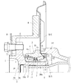
ここで、図3(a)に拡大して示すように、外方部材4のパイロット部15は、車体取付フランジ4bから軸方向に延びる円筒部15aと、この円筒部15aからインナー側の端面に向って漸次縮径するテーパ部15bとで構成されている。また、この外方部材4のパイロット部15の形状に対応して、車軸管14の嵌合部16の形状も、円筒部15aに沿った円筒部16aと、この円筒部16aからインナー側に漸次縮径するテーパ部16bで構成され、ブレーキカバーB/Cを挟持した状態で、車軸管14に複列の転がり軸受2が嵌合される。これにより、軸受部の車軸管14への組立が容易になり、組立作業が簡素化されると共に、軸受部の車軸管14との嵌合部の気密性が高くなる。
Here, as shown in an enlarged view in FIG. 3A, the
そして、本実施形態では、パイロット部15の円筒部15aに断面矩形状の環状溝17が形成され、この環状溝17に断面円形のシールリング18が装着されている。このシールリング18はNBR等の合成ゴムからなり、車軸管14に弾性接触され、外方部材4と車軸管14との嵌合部の僅かな隙間を遮断している。これにより、雨水やダスト等の侵入とデフオイルの漏れを防止して封止効果を高め、長期間に亘って信頼性を確保した車輪用軸受装置を提供することができる。なお、シールリング18の材質としては、NBR以外にも、例えば、耐熱性に優れたHNBR(水素化アクリロニトリル−ブタジエンゴム)、EPDM(エチレン・プロピレンゴム)等をはじめ、ACM(ポリアクリルゴム)や、FKM(フッ素ゴム)、あるいはシリコンゴム等を例示することができる。特に、この種のデフオイルに触れる用途に対しては耐熱性、耐薬品性に優れたACM、FKM、EPDM、シリコンゴムが好ましい。
In this embodiment, an
このシールリング18は、ゴム物性値の圧縮永久歪が120℃×70時間で40%以下、TR10値(伸長率50%)が−20℃以下のものが使用されている。これにより、低温領域でも歪みの回復性が良好となり、所望の封止効果を維持することができる。なお、こので、TR10値とは、予め付与した歪みが10%回復した時の温度を示し、この値の近傍がゴム材料の低温限界値として経験的に用いられている。
This
また、シールリング18の装着前の内径が環状溝17の溝底径よりも小径に設定されている。これにより、シールリング18が装着された時にシメシロを有することになり、車軸管14に軸受部を組み立てる際に、シールリング18が撓んで車軸管14に噛み込むのを防止することができる。逆の構成として、車軸管に環状溝を形成し、この環状溝に予めシールリングを装着する方法も考えられるが、この場合、車軸管に軸受部を組み立てる際、シールリングが外方部材に接触して環状溝から脱落し、噛み込まれる恐れがあるから好ましくない。
Further, the inner diameter of the
また、本実施形態では、(b)に示すように、外方部材4の複列の外側転走面4aに高周波焼入れにより所定の硬化層19が形成され(図中クロスハッチングにて示す)、この硬化層19の有効硬化層深さが2〜4.5mmの範囲に設定されている。そして、シールリング18が装着される環状溝17と外側転走面4aとの最短距離Lが4.5mm以上になるように環状溝17が配設されている。これにより、環状溝17が焼入れによる熱影響を受けず、熱処理変形が防止できると共に、焼き抜け等で強度が低下するのを防止でき、信頼性を向上させることができる。
In the present embodiment, as shown in (b), a predetermined
さらに、環状溝17の隅Rのうち外側転走面4aに近い側、ここでは、インナー側の隅R(R2)がアウター側の隅R(R1)よりも大きく(R2>R1)なるように設定されている。これにより、同じ隅R(R1=R2)とした場合よりも実質的に外側転走面4aからの距離が大きくなるため、熱処理変形に対して有利となると共に、繰り返し曲げ荷重等が負荷された際の強度が高くなり、耐久性を向上させることができる。
Further, the corner R of the
また、シールリング18の色相は、赤色、黄色、オレンジ色、黄緑色等の暖系色に設定されている。これにより、組立時のシールリング18の装着忘れや装着確認の際の見逃しを防止することができ、組立作業の簡素化ができる。
Further, the hue of the
また、シールリング18には予め軸受内部に封入されるグリースと同一のグリースが塗布され、このグリースが表面に付着した状態で装着される。これにより、シールリング18の装着性が向上すると共に、組立の際にシールリング18が車軸管14に接触しても撓むことなくスムーズに車軸管14に軸受部を嵌合させることができる。
The
図4(a)に変形例を示す。この外方部材20のパイロット部21は、車体取付フランジ4bから軸方向に延びる円筒部21aと、この円筒部21aからインナー側の端面に向って漸次縮径するテーパ部21bとで構成され、ブレーキカバーB/Cを挟持した状態で、車軸管14に外方部材20が嵌合されている。そして、本実施形態では、パイロット部21のテーパ部21bに断面矩形状の環状溝22が形成され、この環状溝22に断面円形のシールリング23が装着されている。
FIG. 4A shows a modification. The
このシールリング23はACMからなり、断面略円形に成形され、車軸管14のテーパ部16bに弾性接触されている。そして、(b)に示すように、シールリング23単体での内径d2が、環状溝22の溝底径d1よりも小径(d2<d1)に設定されていると共に、装着後のシールリング23の外径d3が、車軸管14の円筒部16aの内径d4よりも小径(d3<d4)に設定されている。これにより、車軸管14に軸受部を組み立てる際に、シールリング23が車軸管14に噛み込むのを確実に防止することができる。
The
また、本実施形態では、図5(a)に示すように、外方部材20の複列の外側転走面4aに高周波焼入れにより所定の硬化層19が形成され(図中クロスハッチングにて示す)、この硬化層19の有効硬化層深さが2〜4.5mmの範囲に設定されている。そして、シールリング23が装着される環状溝22と外側転走面4aとの最短距離Lが4.5mm以上になるように環状溝22が配設されている。これにより、環状溝22が焼入れによる熱影響を受けず、熱処理変形が防止できると共に、焼き抜け等で強度が低下するのを防止できる。
Moreover, in this embodiment, as shown to Fig.5 (a), the predetermined hardening
さらに、環状溝22の隅Rのうち外側転走面4aに近い側、ここでは、アウター側の隅R(R3)がインナー側の隅R(R4)よりも大きく(R3>R4)なるように設定されている。これにより、同じ隅R(R3=R4)とした場合よりも実質的に外側転走面4aからの距離が大きくなるため、熱処理変形に対して有利となる。
Further, the corner R of the
(b)に示す外方部材24は(a)の外方部材20の変形で、パイロット部21のテーパ部21bにシールリング23が装着される環状溝25が形成されている。この環状溝25は、溝底部の形状が単一の曲率半径R0からなる断面略半円形に形成されている。これにより、焼入れによる熱影響を受け難く、また、切欠き効果による強度低下を抑制することができる。
The
以上、本発明の実施の形態について説明を行ったが、本発明はこうした実施の形態に何等限定されるものではなく、あくまで例示であって、本発明の要旨を逸脱しない範囲内において、さらに種々なる形態で実施し得ることは勿論のことであり、本発明の範囲は、特許請求の範囲の記載によって示され、さらに特許請求の範囲に記載の均等の意味、および範囲内のすべての変更を含む。 The embodiment of the present invention has been described above, but the present invention is not limited to such an embodiment, and is merely an example, and various modifications can be made without departing from the scope of the present invention. Of course, the scope of the present invention is indicated by the description of the scope of claims, and further, the equivalent meanings described in the scope of claims and all modifications within the scope of the scope of the present invention are included. Including.
本発明に係る車輪用軸受装置は、駆動軸と車軸管の開口部に車輪用軸受が装着され、車輪を回転自在に支承するセミフローティングタイプの車輪用軸受装置に適用できる。 The wheel bearing device according to the present invention can be applied to a semi-floating type wheel bearing device in which wheel bearings are mounted in openings of a drive shaft and an axle tube, and the wheels are rotatably supported.
1 ハブ輪
1a ハブ輪の肩部
2 複列の転がり軸受
3 内方部材
4、20、24 外方部材
4a 外側転走面
4b 車体取付フランジ
5 転動体
6 車輪取付フランジ
7 小径段部
8 セレーション
9 キャップ
9a 芯金
9b 弾性部材
10 内輪
10a 内側転走面
10b 大鍔
10c 小鍔
11 保持器
12 シール
13 加締部
14 車軸管
15、21 外方部材のパイロット部
15a、16a、21a 円筒部
15b、16b、21b テーパ部
16 車軸管の嵌合部
17、22、25 環状溝
18、23 シールリング
19 外側転走面の硬化層
51 ハブ輪
52 複列の転がり軸受
53 内方部材
54 外方部材
54a 外側転走面
54b 車体取付フランジ
55 円錐ころ
56 車輪取付フランジ
57 小径段部
58 セレーション
59 加締部
60 内輪
60a 内側転走面
61 キャップ
61a 芯金
61b 弾性部材
B ブレーキロータ
B/C ブレーキカバー
D/S 駆動軸
d1 環状溝の溝底径
d2 シールリングの内径
d3 シールリング装着後の外径
d4 車軸管の円筒部の内径
H 車軸管
R0 環状溝の隅R
R1、R3 環状溝のアウター側の隅R
R2、R4 環状溝のインナー側の隅R
W 車輪
DESCRIPTION OF
R1, R3 Corner R on the outer side of the annular groove
R2, R4 Corner R on the inner side of the annular groove
W wheel
Claims (8)
前記駆動軸に結合され、車輪を取り付けるための車輪取付フランジを一体に有し、外周に軸方向に延びる円筒状の小径段部が形成されたハブ輪、およびこのハブ輪の小径段部と前記車軸管の開口部との間に嵌合され、前記車輪を回転自在に支承する車輪用軸受とを備え、
この車輪用軸受が、外周に前記車軸管に取り付けられるための車体取付フランジと、インナー側の端部に前記車軸管に内嵌されるパイロット部を一体に有し、内周に複列の外側転走面が一体に形成された外方部材と、
前記ハブ輪の小径段部に圧入され、前記複列の外側転走面に対向する内側転走面が形成された少なくとも一つの内輪とからなる内方部材と、
この内方部材と前記外方部材の両転走面間に保持器を介して転動自在に収容された複列の転動体と、
前記外方部材と内方部材との間に形成される環状空間の開口部に装着されたシールとを備えた車輪用軸受装置において、
前記外方部材のパイロット部が、前記車体取付フランジから軸方向に延びる円筒部と、この円筒部からインナー側の端面に向って漸次縮径するテーパ部とで構成され、前記車軸管の嵌合部が前記外方部材のパイロット部の形状に対応して形成されると共に、前記外方部材のパイロット部のテーパ部に環状溝が形成され、この環状溝に合成ゴムからなるシールリングが装着されて前記車軸管に弾性接触され、当該シールリングの装着後の外径が、前記車軸管の円筒部の内径よりも小径に設定されて前記外方部材と車軸管との嵌合部の僅かな隙間が遮断されていることを特徴とする車輪用軸受装置。 An axle tube that is inserted into the drive shaft connected to the differential and supported on the lower surface of the vehicle body;
A hub wheel coupled to the drive shaft and integrally including a wheel mounting flange for mounting a wheel and having a cylindrical small-diameter step portion extending in the axial direction on the outer periphery, and the small-diameter step portion of the hub wheel and the hub wheel A wheel bearing fitted between the opening of the axle tube and rotatably supporting the wheel;
This wheel bearing integrally has a vehicle body mounting flange for mounting to the axle tube on the outer periphery, and a pilot portion fitted into the axle tube on the inner end, and has a double row outside on the inner periphery. An outer member integrally formed with a rolling surface;
An inner member formed of at least one inner ring press-fitted into the small-diameter step portion of the hub wheel and formed with an inner rolling surface facing the outer rolling surface of the double row;
A double row rolling element housed between the rolling surfaces of the inner member and the outer member so as to be freely rollable via a cage;
In a wheel bearing device comprising a seal mounted in an opening of an annular space formed between the outer member and the inner member,
A pilot portion of the outer member includes a cylindrical portion that extends in the axial direction from the vehicle body mounting flange, and a tapered portion that gradually decreases in diameter from the cylindrical portion toward the end surface on the inner side. Are formed corresponding to the shape of the pilot portion of the outer member, and an annular groove is formed in the tapered portion of the pilot portion of the outer member, and a seal ring made of synthetic rubber is attached to the annular groove. Elastically contacting the axle tube, and the outer diameter of the seal ring after mounting is set to be smaller than the inner diameter of the cylindrical portion of the axle tube, so that the fitting portion between the outer member and the axle tube is slightly A bearing device for a wheel, wherein the gap is blocked.
Priority Applications (5)
| Application Number | Priority Date | Filing Date | Title |
|---|---|---|---|
| JP2010112824A JP5560090B2 (en) | 2010-05-17 | 2010-05-17 | Wheel bearing device |
| CN201180024334.7A CN102939208B (en) | 2010-05-17 | 2011-05-16 | Bearing device for wheel |
| EP11783512.4A EP2572901B1 (en) | 2010-05-17 | 2011-05-16 | Bearing device for wheel |
| PCT/JP2011/061234 WO2011145578A1 (en) | 2010-05-17 | 2011-05-16 | Bearing device for wheel |
| US13/677,427 US8777492B2 (en) | 2010-05-17 | 2012-11-15 | Wheel bearing apparatus |
Applications Claiming Priority (1)
| Application Number | Priority Date | Filing Date | Title |
|---|---|---|---|
| JP2010112824A JP5560090B2 (en) | 2010-05-17 | 2010-05-17 | Wheel bearing device |
Publications (3)
| Publication Number | Publication Date |
|---|---|
| JP2011240755A JP2011240755A (en) | 2011-12-01 |
| JP2011240755A5 JP2011240755A5 (en) | 2013-06-27 |
| JP5560090B2 true JP5560090B2 (en) | 2014-07-23 |
Family
ID=44991681
Family Applications (1)
| Application Number | Title | Priority Date | Filing Date |
|---|---|---|---|
| JP2010112824A Expired - Fee Related JP5560090B2 (en) | 2010-05-17 | 2010-05-17 | Wheel bearing device |
Country Status (5)
| Country | Link |
|---|---|
| US (1) | US8777492B2 (en) |
| EP (1) | EP2572901B1 (en) |
| JP (1) | JP5560090B2 (en) |
| CN (1) | CN102939208B (en) |
| WO (1) | WO2011145578A1 (en) |
Families Citing this family (11)
| Publication number | Priority date | Publication date | Assignee | Title |
|---|---|---|---|---|
| JP2015010681A (en) * | 2013-07-01 | 2015-01-19 | 株式会社ジェイテクト | Bearing unit |
| JP2017082945A (en) * | 2015-10-29 | 2017-05-18 | Ntn株式会社 | Double row tapered roller bearing, race ring and method of manufacturing double row tapered roller bearing |
| ITUB20160674A1 (en) * | 2016-02-11 | 2017-08-11 | Fpt Ind Spa | WHEEL HUB WITH IMPROVED SEALING SYSTEM |
| IT201700058071A1 (en) * | 2017-05-29 | 2018-11-29 | Skf Ab | HUB-WHEEL BEARING GROUP |
| US20230003256A1 (en) * | 2017-10-24 | 2023-01-05 | Ntn Corporation | Wheel bearing device and method for manufacturing said device |
| JP6936695B2 (en) | 2017-10-24 | 2021-09-22 | Ntn株式会社 | Wheel bearing equipment and its manufacturing method |
| DE102017222310A1 (en) * | 2017-12-08 | 2019-06-13 | Aktiebolaget Skf | Wheel bearing unit and pre-assembly process |
| DE102019212595A1 (en) * | 2018-09-07 | 2020-03-12 | Aktiebolaget Skf | Sealing device for a wheel bearing unit |
| DE102019212747A1 (en) * | 2018-09-10 | 2020-04-30 | Aktiebolaget Skf | Sealing device for a wheel bearing unit |
| JP7441609B2 (en) * | 2019-03-25 | 2024-03-01 | Ntn株式会社 | Bearing device for wheels |
| IT202000026608A1 (en) * | 2020-11-09 | 2022-05-09 | Skf Ab | LOW CARBON STEEL BEARING UNIT |
Family Cites Families (29)
| Publication number | Priority date | Publication date | Assignee | Title |
|---|---|---|---|---|
| US3854735A (en) * | 1972-10-24 | 1974-12-17 | Exxon Production Research Co | Static face seal |
| US4692040A (en) * | 1985-05-06 | 1987-09-08 | The Torrington Company | Multirow roller bearing with seals between the races |
| JP2524095Y2 (en) * | 1991-04-15 | 1997-01-29 | 住友電装株式会社 | Cap for high-pressure connections in automotive engines |
| JPH0679606A (en) | 1992-08-27 | 1994-03-22 | Koike Sanso Kogyo Co Ltd | Grinding device |
| JP2597023Y2 (en) * | 1992-11-05 | 1999-06-28 | 日本精工株式会社 | Rolling bearing unit for semi-floating axle with rotation speed detector |
| JPH0679606U (en) * | 1993-04-27 | 1994-11-08 | エヌティエヌ株式会社 | Wheel support device |
| JP3862453B2 (en) * | 1999-09-10 | 2006-12-27 | Ntn株式会社 | Wheel bearing device |
| JP2001150909A (en) * | 1999-11-29 | 2001-06-05 | Nachi Fujikoshi Corp | Rolling bearing unit for vehicle |
| US6386764B1 (en) * | 2000-09-07 | 2002-05-14 | The Timken Company | Bearing unitized for handling |
| JP4135355B2 (en) * | 2001-11-12 | 2008-08-20 | 株式会社ジェイテクト | Vehicle bearing device |
| JP4318205B2 (en) * | 2003-06-23 | 2009-08-19 | Ntn株式会社 | Rolling bearing for wheel and bearing device for semi-floating wheel provided with the same |
| JP2005054994A (en) * | 2003-07-24 | 2005-03-03 | Ntn Corp | Rolling bearing for wheels and bearing device for half-floating type wheels equipped therewith |
| JP2005042894A (en) * | 2003-07-25 | 2005-02-17 | Nsk Ltd | Double row rolling bearing device |
| JP2005104260A (en) * | 2003-09-30 | 2005-04-21 | Nsk Ltd | Wheel supporting device |
| JP4716481B2 (en) * | 2003-12-01 | 2011-07-06 | Ntn株式会社 | Wheel bearing device |
| JP2005195168A (en) * | 2003-12-10 | 2005-07-21 | Ntn Corp | Bearing for wheel and semi-floating type bearing unit equipped with the same |
| CN100469600C (en) * | 2003-12-10 | 2009-03-18 | Ntn株式会社 | Wheel bearing and semi-floating type wheel bearing device having the same |
| ITTO20031031A1 (en) * | 2003-12-22 | 2005-06-23 | Skf Ab | SEALING DEVICE FOR A HUB-WHEEL GROUP. |
| JP2005321375A (en) * | 2004-04-09 | 2005-11-17 | Ntn Corp | Bearing device for wheel with rotation speed detector |
| JP2005297744A (en) * | 2004-04-09 | 2005-10-27 | Honda Motor Co Ltd | Underwater motor scooter |
| ITTO20040330A1 (en) * | 2004-05-19 | 2004-08-19 | Skf Ab | SEALING DEVICE FOR A WHEEL-MOUNT ASSEMBLY |
| US20070217728A1 (en) * | 2004-09-30 | 2007-09-20 | Shinichirou Kashiwagi | Hub Unit, Rolling Bearing Assembly and Manufacture Method Thereof, as Well as Assembling Apparatus for Rolling Bearing Assebly and Assebly Method Thereof |
| JP2006118563A (en) * | 2004-10-20 | 2006-05-11 | Jtekt Corp | Wheel bearing device |
| WO2006080092A1 (en) | 2005-01-27 | 2006-08-03 | Ntn Corporation | A bearing apparatus for a wheel of vehicle |
| JP4672530B2 (en) * | 2005-11-17 | 2011-04-20 | 日東電工株式会社 | Ventilation member |
| JP2007326402A (en) * | 2006-06-06 | 2007-12-20 | Ntn Corp | Bearing system for wheel |
| JP2008045674A (en) * | 2006-08-17 | 2008-02-28 | Ntn Corp | Wheel bearing device |
| US9404531B2 (en) * | 2007-02-23 | 2016-08-02 | Ntn Corporation | Bearing apparatus for wheel |
| JP5183358B2 (en) * | 2008-08-22 | 2013-04-17 | Ntn株式会社 | Wheel bearing device |
-
2010
- 2010-05-17 JP JP2010112824A patent/JP5560090B2/en not_active Expired - Fee Related
-
2011
- 2011-05-16 WO PCT/JP2011/061234 patent/WO2011145578A1/en active Application Filing
- 2011-05-16 EP EP11783512.4A patent/EP2572901B1/en not_active Not-in-force
- 2011-05-16 CN CN201180024334.7A patent/CN102939208B/en not_active Expired - Fee Related
-
2012
- 2012-11-15 US US13/677,427 patent/US8777492B2/en not_active Expired - Fee Related
Also Published As
| Publication number | Publication date |
|---|---|
| EP2572901A4 (en) | 2014-11-26 |
| EP2572901B1 (en) | 2017-08-09 |
| WO2011145578A1 (en) | 2011-11-24 |
| CN102939208B (en) | 2015-07-08 |
| JP2011240755A (en) | 2011-12-01 |
| EP2572901A1 (en) | 2013-03-27 |
| US20130076111A1 (en) | 2013-03-28 |
| CN102939208A (en) | 2013-02-20 |
| US8777492B2 (en) | 2014-07-15 |
Similar Documents
| Publication | Publication Date | Title |
|---|---|---|
| JP5560090B2 (en) | Wheel bearing device | |
| JP4873606B2 (en) | Wheel bearing device | |
| US8449197B2 (en) | Bearing apparatus for a wheel of vehicle | |
| WO2011118805A1 (en) | Bearing device for wheel | |
| JP2012056411A (en) | Wheel bearing device | |
| JP5252489B2 (en) | Drive wheel support device | |
| JP2006349059A (en) | Bearing device for wheel | |
| JP2005195168A (en) | Bearing for wheel and semi-floating type bearing unit equipped with the same | |
| JP2007192392A (en) | Bearing device for wheel | |
| JP2007057014A (en) | Double row tapered roll bearing for wheel | |
| JP2011148409A (en) | Bearing device for wheel | |
| JP2007211791A (en) | Wheel bearing device | |
| JP2007232116A (en) | Wheel bearing device | |
| JP2009156428A (en) | Seal assembly method | |
| JP2007162828A (en) | Wheel bearing device and axle module equipped therewith | |
| JP2006046401A (en) | Bearing device for wheel | |
| JP6483460B2 (en) | SEALING DEVICE AND WHEEL BEARING DEVICE HAVING THE SAME | |
| JP2013040664A (en) | Wheel bearing device | |
| JP4936373B2 (en) | Wheel bearing device | |
| JP2009191858A (en) | Seal for wheel bearing device, and wheel bearing device assembling method | |
| JP2010001969A (en) | Bearing seal for wheel and bearing device for wheel having the same | |
| JP2007024208A (en) | Bearing device for wheel | |
| WO2013018868A1 (en) | Wheel bearing device | |
| JP4948149B2 (en) | Wheel bearing device | |
| JP5501595B2 (en) | Wheel bearing device |
Legal Events
| Date | Code | Title | Description |
|---|---|---|---|
| A521 | Request for written amendment filed |
Free format text: JAPANESE INTERMEDIATE CODE: A523 Effective date: 20130509 |
|
| A621 | Written request for application examination |
Free format text: JAPANESE INTERMEDIATE CODE: A621 Effective date: 20130509 |
|
| A131 | Notification of reasons for refusal |
Free format text: JAPANESE INTERMEDIATE CODE: A131 Effective date: 20140224 |
|
| A521 | Request for written amendment filed |
Free format text: JAPANESE INTERMEDIATE CODE: A523 Effective date: 20140410 |
|
| TRDD | Decision of grant or rejection written | ||
| A01 | Written decision to grant a patent or to grant a registration (utility model) |
Free format text: JAPANESE INTERMEDIATE CODE: A01 Effective date: 20140516 |
|
| A61 | First payment of annual fees (during grant procedure) |
Free format text: JAPANESE INTERMEDIATE CODE: A61 Effective date: 20140609 |
|
| R150 | Certificate of patent or registration of utility model |
Ref document number: 5560090 Country of ref document: JP Free format text: JAPANESE INTERMEDIATE CODE: R150 |
|
| R250 | Receipt of annual fees |
Free format text: JAPANESE INTERMEDIATE CODE: R250 |
|
| R250 | Receipt of annual fees |
Free format text: JAPANESE INTERMEDIATE CODE: R250 |
|
| R250 | Receipt of annual fees |
Free format text: JAPANESE INTERMEDIATE CODE: R250 |
|
| R250 | Receipt of annual fees |
Free format text: JAPANESE INTERMEDIATE CODE: R250 |
|
| R250 | Receipt of annual fees |
Free format text: JAPANESE INTERMEDIATE CODE: R250 |
|
| LAPS | Cancellation because of no payment of annual fees |