JP2017082945A - Double row tapered roller bearing, race ring and method of manufacturing double row tapered roller bearing - Google Patents
Double row tapered roller bearing, race ring and method of manufacturing double row tapered roller bearing Download PDFInfo
- Publication number
- JP2017082945A JP2017082945A JP2015213092A JP2015213092A JP2017082945A JP 2017082945 A JP2017082945 A JP 2017082945A JP 2015213092 A JP2015213092 A JP 2015213092A JP 2015213092 A JP2015213092 A JP 2015213092A JP 2017082945 A JP2017082945 A JP 2017082945A
- Authority
- JP
- Japan
- Prior art keywords
- ring
- region
- tapered roller
- groove
- roller bearing
- Prior art date
- Legal status (The legal status is an assumption and is not a legal conclusion. Google has not performed a legal analysis and makes no representation as to the accuracy of the status listed.)
- Pending
Links
- 238000004519 manufacturing process Methods 0.000 title claims abstract description 41
- 238000005096 rolling process Methods 0.000 claims abstract description 31
- 238000000034 method Methods 0.000 claims description 42
- 230000002093 peripheral effect Effects 0.000 claims description 40
- 238000010438 heat treatment Methods 0.000 claims description 35
- 238000001816 cooling Methods 0.000 claims description 21
- 229910000831 Steel Inorganic materials 0.000 claims description 11
- 230000006698 induction Effects 0.000 claims description 11
- 239000010959 steel Substances 0.000 claims description 11
- 238000010791 quenching Methods 0.000 description 15
- 230000000171 quenching effect Effects 0.000 description 11
- 238000010586 diagram Methods 0.000 description 8
- 238000005255 carburizing Methods 0.000 description 7
- 125000006850 spacer group Chemical group 0.000 description 6
- 239000000463 material Substances 0.000 description 4
- 230000000694 effects Effects 0.000 description 3
- 125000004122 cyclic group Chemical group 0.000 description 2
- 230000007547 defect Effects 0.000 description 2
- 238000003754 machining Methods 0.000 description 2
- 229910000734 martensite Inorganic materials 0.000 description 2
- 239000002245 particle Substances 0.000 description 2
- 239000002344 surface layer Substances 0.000 description 2
- 238000005496 tempering Methods 0.000 description 2
- 230000009466 transformation Effects 0.000 description 2
- 229910001018 Cast iron Inorganic materials 0.000 description 1
- 238000005422 blasting Methods 0.000 description 1
- 230000000052 comparative effect Effects 0.000 description 1
- 239000012141 concentrate Substances 0.000 description 1
- 239000000110 cooling liquid Substances 0.000 description 1
- 238000005553 drilling Methods 0.000 description 1
- 238000007730 finishing process Methods 0.000 description 1
- 238000005242 forging Methods 0.000 description 1
- 238000007542 hardness measurement Methods 0.000 description 1
- 239000010410 layer Substances 0.000 description 1
- 239000002923 metal particle Substances 0.000 description 1
- 239000000203 mixture Substances 0.000 description 1
- 238000012986 modification Methods 0.000 description 1
- 230000004048 modification Effects 0.000 description 1
- 238000005498 polishing Methods 0.000 description 1
- 238000002360 preparation method Methods 0.000 description 1
- 230000002265 prevention Effects 0.000 description 1
- 230000005855 radiation Effects 0.000 description 1
- 238000005507 spraying Methods 0.000 description 1
- XLYOFNOQVPJJNP-UHFFFAOYSA-N water Substances O XLYOFNOQVPJJNP-UHFFFAOYSA-N 0.000 description 1
Images


Classifications
-
- C—CHEMISTRY; METALLURGY
- C21—METALLURGY OF IRON
- C21D—MODIFYING THE PHYSICAL STRUCTURE OF FERROUS METALS; GENERAL DEVICES FOR HEAT TREATMENT OF FERROUS OR NON-FERROUS METALS OR ALLOYS; MAKING METAL MALLEABLE, e.g. BY DECARBURISATION OR TEMPERING
- C21D9/00—Heat treatment, e.g. annealing, hardening, quenching or tempering, adapted for particular articles; Furnaces therefor
- C21D9/40—Heat treatment, e.g. annealing, hardening, quenching or tempering, adapted for particular articles; Furnaces therefor for rings; for bearing races
-
- C—CHEMISTRY; METALLURGY
- C21—METALLURGY OF IRON
- C21D—MODIFYING THE PHYSICAL STRUCTURE OF FERROUS METALS; GENERAL DEVICES FOR HEAT TREATMENT OF FERROUS OR NON-FERROUS METALS OR ALLOYS; MAKING METAL MALLEABLE, e.g. BY DECARBURISATION OR TEMPERING
- C21D1/00—General methods or devices for heat treatment, e.g. annealing, hardening, quenching or tempering
- C21D1/06—Surface hardening
- C21D1/09—Surface hardening by direct application of electrical or wave energy; by particle radiation
- C21D1/10—Surface hardening by direct application of electrical or wave energy; by particle radiation by electric induction
-
- C—CHEMISTRY; METALLURGY
- C21—METALLURGY OF IRON
- C21D—MODIFYING THE PHYSICAL STRUCTURE OF FERROUS METALS; GENERAL DEVICES FOR HEAT TREATMENT OF FERROUS OR NON-FERROUS METALS OR ALLOYS; MAKING METAL MALLEABLE, e.g. BY DECARBURISATION OR TEMPERING
- C21D1/00—General methods or devices for heat treatment, e.g. annealing, hardening, quenching or tempering
- C21D1/18—Hardening; Quenching with or without subsequent tempering
-
- F—MECHANICAL ENGINEERING; LIGHTING; HEATING; WEAPONS; BLASTING
- F16—ENGINEERING ELEMENTS AND UNITS; GENERAL MEASURES FOR PRODUCING AND MAINTAINING EFFECTIVE FUNCTIONING OF MACHINES OR INSTALLATIONS; THERMAL INSULATION IN GENERAL
- F16C—SHAFTS; FLEXIBLE SHAFTS; ELEMENTS OR CRANKSHAFT MECHANISMS; ROTARY BODIES OTHER THAN GEARING ELEMENTS; BEARINGS
- F16C19/00—Bearings with rolling contact, for exclusively rotary movement
- F16C19/22—Bearings with rolling contact, for exclusively rotary movement with bearing rollers essentially of the same size in one or more circular rows, e.g. needle bearings
- F16C19/34—Bearings with rolling contact, for exclusively rotary movement with bearing rollers essentially of the same size in one or more circular rows, e.g. needle bearings for both radial and axial load
- F16C19/38—Bearings with rolling contact, for exclusively rotary movement with bearing rollers essentially of the same size in one or more circular rows, e.g. needle bearings for both radial and axial load with two or more rows of rollers
- F16C19/383—Bearings with rolling contact, for exclusively rotary movement with bearing rollers essentially of the same size in one or more circular rows, e.g. needle bearings for both radial and axial load with two or more rows of rollers with tapered rollers, i.e. rollers having essentially the shape of a truncated cone
- F16C19/385—Bearings with rolling contact, for exclusively rotary movement with bearing rollers essentially of the same size in one or more circular rows, e.g. needle bearings for both radial and axial load with two or more rows of rollers with tapered rollers, i.e. rollers having essentially the shape of a truncated cone with two rows, i.e. double-row tapered roller bearings
- F16C19/386—Bearings with rolling contact, for exclusively rotary movement with bearing rollers essentially of the same size in one or more circular rows, e.g. needle bearings for both radial and axial load with two or more rows of rollers with tapered rollers, i.e. rollers having essentially the shape of a truncated cone with two rows, i.e. double-row tapered roller bearings in O-arrangement
-
- F—MECHANICAL ENGINEERING; LIGHTING; HEATING; WEAPONS; BLASTING
- F16—ENGINEERING ELEMENTS AND UNITS; GENERAL MEASURES FOR PRODUCING AND MAINTAINING EFFECTIVE FUNCTIONING OF MACHINES OR INSTALLATIONS; THERMAL INSULATION IN GENERAL
- F16C—SHAFTS; FLEXIBLE SHAFTS; ELEMENTS OR CRANKSHAFT MECHANISMS; ROTARY BODIES OTHER THAN GEARING ELEMENTS; BEARINGS
- F16C33/00—Parts of bearings; Special methods for making bearings or parts thereof
- F16C33/30—Parts of ball or roller bearings
- F16C33/58—Raceways; Race rings
- F16C33/583—Details of specific parts of races
- F16C33/585—Details of specific parts of races of raceways, e.g. ribs to guide the rollers
-
- F—MECHANICAL ENGINEERING; LIGHTING; HEATING; WEAPONS; BLASTING
- F16—ENGINEERING ELEMENTS AND UNITS; GENERAL MEASURES FOR PRODUCING AND MAINTAINING EFFECTIVE FUNCTIONING OF MACHINES OR INSTALLATIONS; THERMAL INSULATION IN GENERAL
- F16C—SHAFTS; FLEXIBLE SHAFTS; ELEMENTS OR CRANKSHAFT MECHANISMS; ROTARY BODIES OTHER THAN GEARING ELEMENTS; BEARINGS
- F16C33/00—Parts of bearings; Special methods for making bearings or parts thereof
- F16C33/30—Parts of ball or roller bearings
- F16C33/58—Raceways; Race rings
- F16C33/60—Raceways; Race rings divided or split, e.g. comprising two juxtaposed rings
- F16C33/605—Raceways; Race rings divided or split, e.g. comprising two juxtaposed rings with a separate retaining member, e.g. flange, shoulder, guide ring, secured to a race ring, adjacent to the race surface, so as to abut the end of the rolling elements, e.g. rollers, or the cage
-
- F—MECHANICAL ENGINEERING; LIGHTING; HEATING; WEAPONS; BLASTING
- F16—ENGINEERING ELEMENTS AND UNITS; GENERAL MEASURES FOR PRODUCING AND MAINTAINING EFFECTIVE FUNCTIONING OF MACHINES OR INSTALLATIONS; THERMAL INSULATION IN GENERAL
- F16C—SHAFTS; FLEXIBLE SHAFTS; ELEMENTS OR CRANKSHAFT MECHANISMS; ROTARY BODIES OTHER THAN GEARING ELEMENTS; BEARINGS
- F16C33/00—Parts of bearings; Special methods for making bearings or parts thereof
- F16C33/30—Parts of ball or roller bearings
- F16C33/58—Raceways; Race rings
- F16C33/64—Special methods of manufacture
-
- F—MECHANICAL ENGINEERING; LIGHTING; HEATING; WEAPONS; BLASTING
- F16—ENGINEERING ELEMENTS AND UNITS; GENERAL MEASURES FOR PRODUCING AND MAINTAINING EFFECTIVE FUNCTIONING OF MACHINES OR INSTALLATIONS; THERMAL INSULATION IN GENERAL
- F16C—SHAFTS; FLEXIBLE SHAFTS; ELEMENTS OR CRANKSHAFT MECHANISMS; ROTARY BODIES OTHER THAN GEARING ELEMENTS; BEARINGS
- F16C43/00—Assembling bearings
- F16C43/04—Assembling rolling-contact bearings
-
- C—CHEMISTRY; METALLURGY
- C21—METALLURGY OF IRON
- C21D—MODIFYING THE PHYSICAL STRUCTURE OF FERROUS METALS; GENERAL DEVICES FOR HEAT TREATMENT OF FERROUS OR NON-FERROUS METALS OR ALLOYS; MAKING METAL MALLEABLE, e.g. BY DECARBURISATION OR TEMPERING
- C21D2221/00—Treating localised areas of an article
- C21D2221/01—End parts (e.g. leading, trailing end)
-
- C—CHEMISTRY; METALLURGY
- C21—METALLURGY OF IRON
- C21D—MODIFYING THE PHYSICAL STRUCTURE OF FERROUS METALS; GENERAL DEVICES FOR HEAT TREATMENT OF FERROUS OR NON-FERROUS METALS OR ALLOYS; MAKING METAL MALLEABLE, e.g. BY DECARBURISATION OR TEMPERING
- C21D2221/00—Treating localised areas of an article
- C21D2221/02—Edge parts
-
- C—CHEMISTRY; METALLURGY
- C21—METALLURGY OF IRON
- C21D—MODIFYING THE PHYSICAL STRUCTURE OF FERROUS METALS; GENERAL DEVICES FOR HEAT TREATMENT OF FERROUS OR NON-FERROUS METALS OR ALLOYS; MAKING METAL MALLEABLE, e.g. BY DECARBURISATION OR TEMPERING
- C21D2221/00—Treating localised areas of an article
- C21D2221/10—Differential treatment of inner with respect to outer regions, e.g. core and periphery, respectively
-
- F—MECHANICAL ENGINEERING; LIGHTING; HEATING; WEAPONS; BLASTING
- F16—ENGINEERING ELEMENTS AND UNITS; GENERAL MEASURES FOR PRODUCING AND MAINTAINING EFFECTIVE FUNCTIONING OF MACHINES OR INSTALLATIONS; THERMAL INSULATION IN GENERAL
- F16C—SHAFTS; FLEXIBLE SHAFTS; ELEMENTS OR CRANKSHAFT MECHANISMS; ROTARY BODIES OTHER THAN GEARING ELEMENTS; BEARINGS
- F16C2223/00—Surface treatments; Hardening; Coating
- F16C2223/10—Hardening, e.g. carburizing, carbo-nitriding
- F16C2223/18—Hardening, e.g. carburizing, carbo-nitriding with induction hardening
-
- F—MECHANICAL ENGINEERING; LIGHTING; HEATING; WEAPONS; BLASTING
- F16—ENGINEERING ELEMENTS AND UNITS; GENERAL MEASURES FOR PRODUCING AND MAINTAINING EFFECTIVE FUNCTIONING OF MACHINES OR INSTALLATIONS; THERMAL INSULATION IN GENERAL
- F16C—SHAFTS; FLEXIBLE SHAFTS; ELEMENTS OR CRANKSHAFT MECHANISMS; ROTARY BODIES OTHER THAN GEARING ELEMENTS; BEARINGS
- F16C2240/00—Specified values or numerical ranges of parameters; Relations between them
- F16C2240/30—Angles, e.g. inclinations
-
- F—MECHANICAL ENGINEERING; LIGHTING; HEATING; WEAPONS; BLASTING
- F16—ENGINEERING ELEMENTS AND UNITS; GENERAL MEASURES FOR PRODUCING AND MAINTAINING EFFECTIVE FUNCTIONING OF MACHINES OR INSTALLATIONS; THERMAL INSULATION IN GENERAL
- F16C—SHAFTS; FLEXIBLE SHAFTS; ELEMENTS OR CRANKSHAFT MECHANISMS; ROTARY BODIES OTHER THAN GEARING ELEMENTS; BEARINGS
- F16C2360/00—Engines or pumps
- F16C2360/31—Wind motors
-
- F—MECHANICAL ENGINEERING; LIGHTING; HEATING; WEAPONS; BLASTING
- F16—ENGINEERING ELEMENTS AND UNITS; GENERAL MEASURES FOR PRODUCING AND MAINTAINING EFFECTIVE FUNCTIONING OF MACHINES OR INSTALLATIONS; THERMAL INSULATION IN GENERAL
- F16C—SHAFTS; FLEXIBLE SHAFTS; ELEMENTS OR CRANKSHAFT MECHANISMS; ROTARY BODIES OTHER THAN GEARING ELEMENTS; BEARINGS
- F16C33/00—Parts of bearings; Special methods for making bearings or parts thereof
- F16C33/30—Parts of ball or roller bearings
- F16C33/46—Cages for rollers or needles
- F16C33/52—Cages for rollers or needles with no part entering between, or touching, the bearing surfaces of the rollers
- F16C33/523—Cages for rollers or needles with no part entering between, or touching, the bearing surfaces of the rollers with pins extending into holes or bores on the axis of the rollers
- F16C33/526—Cages for rollers or needles with no part entering between, or touching, the bearing surfaces of the rollers with pins extending into holes or bores on the axis of the rollers extending through the rollers and joining two lateral cage parts
-
- Y—GENERAL TAGGING OF NEW TECHNOLOGICAL DEVELOPMENTS; GENERAL TAGGING OF CROSS-SECTIONAL TECHNOLOGIES SPANNING OVER SEVERAL SECTIONS OF THE IPC; TECHNICAL SUBJECTS COVERED BY FORMER USPC CROSS-REFERENCE ART COLLECTIONS [XRACs] AND DIGESTS
- Y02—TECHNOLOGIES OR APPLICATIONS FOR MITIGATION OR ADAPTATION AGAINST CLIMATE CHANGE
- Y02P—CLIMATE CHANGE MITIGATION TECHNOLOGIES IN THE PRODUCTION OR PROCESSING OF GOODS
- Y02P10/00—Technologies related to metal processing
- Y02P10/25—Process efficiency
-
- Y—GENERAL TAGGING OF NEW TECHNOLOGICAL DEVELOPMENTS; GENERAL TAGGING OF CROSS-SECTIONAL TECHNOLOGIES SPANNING OVER SEVERAL SECTIONS OF THE IPC; TECHNICAL SUBJECTS COVERED BY FORMER USPC CROSS-REFERENCE ART COLLECTIONS [XRACs] AND DIGESTS
- Y10—TECHNICAL SUBJECTS COVERED BY FORMER USPC
- Y10T—TECHNICAL SUBJECTS COVERED BY FORMER US CLASSIFICATION
- Y10T29/00—Metal working
- Y10T29/49—Method of mechanical manufacture
- Y10T29/49636—Process for making bearing or component thereof
- Y10T29/49643—Rotary bearing
- Y10T29/49679—Anti-friction bearing or component thereof
- Y10T29/49682—Assembling of race and rolling anti-friction members
- Y10T29/49684—Assembling of race and rolling anti-friction members with race making
Abstract
Description
この発明は、複列円すいころ軸受、軌道輪および複列円すいころ軸受の製造方法に関する。 The present invention relates to a double-row tapered roller bearing, a bearing ring, and a method for manufacturing a double-row tapered roller bearing.
風力発電機用の軸受、たとえばブレードの回転動力を伝達する軸を支持する主軸受については、ブレードやロータの自重に起因する荷重成分の他、風荷重に起因する荷重成分も作用する。つまり、当該軸受にはラジアル荷重に加えてアキシアル荷重も作用する。そのため、従来、風力発電機用の軸受として、複列円すいころ軸受を用いることが提案されている(たとえば、特表2008−546948号公報参照)。 For a wind turbine generator bearing, for example, a main bearing that supports a shaft that transmits the rotational power of a blade, in addition to a load component caused by the weight of the blade and the rotor, a load component caused by a wind load also acts. That is, an axial load acts on the bearing in addition to the radial load. For this reason, it has been conventionally proposed to use a double-row tapered roller bearing as a bearing for a wind power generator (see, for example, JP-T-2008-546948).
上記特表2008−546948号公報に開示されているように、風力発電機に適用された複列円すいころ軸受の外輪には複数のボルト用孔が形成されており、当該ボルト用孔に挿通したボルトにより風力発電機の筐体など周囲の部品と固定される。また、当該複列円すいころ軸受の内輪についても、同様にボルト用孔が形成される場合もある。 As disclosed in the above special table 2008-546948, a plurality of bolt holes are formed in the outer ring of the double row tapered roller bearing applied to the wind power generator, and the bolt holes are inserted into the outer rings. It is fixed to surrounding parts such as a wind power generator housing with bolts. Similarly, a bolt hole may be formed on the inner ring of the double row tapered roller bearing.
このような複列円すいころ軸受の外輪や内輪に関しては、必要な硬度を得るために浸炭鋼を用いて浸炭焼入れを行う、というプロセスが採用されている。これは、以下のような理由による。 For the outer ring and inner ring of such a double-row tapered roller bearing, a process of carburizing and quenching using carburized steel is employed to obtain the required hardness. This is due to the following reasons.
すなわち、上述したように外輪などに形成された複数のボルト用孔については、複列円すいころ軸受を周囲の部品に対して正確に固定するため高い位置精度が求められる。そのため、外輪などに対する熱処理が終了した後に当該ボルト用孔を形成すれば、熱処理前にボルト用孔を形成する場合のように熱処理に伴う外輪の変形などを考慮する必要が無く、作業効率も向上させることができる。一方、熱処理によって外輪などの硬度が高くなると、被削性が低下して機械加工が難しくなる。つまり、外輪などの材料として軸受鋼を用い、熱処理として一般的な全体焼入れを行うと上述したボルト用孔の加工が難しくなるという問題がある。 That is, as described above, the plurality of bolt holes formed in the outer ring or the like requires high positional accuracy in order to accurately fix the double row tapered roller bearing to the surrounding parts. Therefore, if the bolt hole is formed after the heat treatment for the outer ring or the like is completed, there is no need to consider the deformation of the outer ring accompanying the heat treatment as in the case of forming the bolt hole before the heat treatment, and the work efficiency is also improved. Can be made. On the other hand, if the hardness of the outer ring or the like is increased by heat treatment, the machinability is lowered and machining becomes difficult. That is, when bearing steel is used as a material for an outer ring or the like and general quenching is performed as a heat treatment, there is a problem that it is difficult to process the above-described bolt hole.
そこで、上述のように外輪などの材料として浸炭鋼を用い、ボルト用孔が形成されるべき領域に対しては防浸炭処理を施した状態で浸炭焼入れを行うと、防振処理をしていない領域については硬度を高めることができる一方、防浸炭処理を施した領域については硬度上昇を防止しているため、当該浸炭焼入れ後にボルト用孔を形成する加工を容易に行うことができる。 Therefore, if carburized steel is used as a material for the outer ring or the like as described above, and carburizing and quenching is performed on the region where the bolt holes are to be formed, the vibration-proofing treatment is not performed. While it is possible to increase the hardness of the region, since the increase of the hardness is prevented in the region subjected to the carburizing treatment, the process of forming the bolt hole after the carburizing and quenching can be easily performed.
しかし、上記のような浸炭熱処理を行うと、防浸炭処理を施すなど工程数が一般的な焼入れ処理より増加するとともに、一般的な全体焼入れより熱処理自体の処理時間も長くなるため、結果的に製造コストが増大するという問題があった。 However, when the carburizing heat treatment as described above is performed, the number of steps such as performing a carburizing prevention treatment is increased as compared with a general quenching process, and the processing time of the heat treatment itself is longer than a general overall quenching process. There was a problem that the manufacturing cost increased.
この発明は、上記のような課題を解決するためになされたものであり、この発明の目的は、製造コストが抑制された複列円すいころ軸受を提供することである。 The present invention has been made to solve the above-described problems, and an object of the present invention is to provide a double-row tapered roller bearing with reduced manufacturing costs.
本開示に係る複列円すいころ軸受は、環状の形状を有する軌道輪である外輪と、外輪の内周側に配置され、環状の形状を有する軌道輪である内輪と、ころとを備える。内輪には外輪と対向する外周表面に、底面が転走面となる溝が2列形成されている。ころは、内輪の転走面と接するように溝の内部に配置されるとともに、外輪と接する円すい形状のころである。内輪の外周表面において、溝と隣接する領域は、溝の内周面から当該領域にまで延在する硬化領域と、硬化領域より溝から離れた位置に配置されるとともに硬化領域より硬度の低い非硬化領域とを含む。 A double-row tapered roller bearing according to the present disclosure includes an outer ring that is a race ring having an annular shape, an inner ring that is disposed on an inner peripheral side of the outer ring and has a ring shape, and rollers. The inner ring has two rows of grooves with the bottom surface serving as a rolling surface on the outer peripheral surface facing the outer ring. The roller is a conical roller that is disposed in the groove so as to be in contact with the rolling surface of the inner ring and is in contact with the outer ring. On the outer peripheral surface of the inner ring, the region adjacent to the groove is a hardened region extending from the inner peripheral surface of the groove to the region, and is disposed at a position farther from the groove than the hardened region and has a lower hardness than the hardened region. And a cured region.
本開示に係る軌道輪の製造方法は、複列円すいころ軸受の軌道輪の製造方法であって、成形体を準備する工程と、加熱領域を形成する工程と、冷却する工程と、除去する工程とを備える。成形体を準備する工程では、鋼から構成され、底面が軌道輪の転走面となるべき環状の溝が外周面に形成された成形体を準備する。加熱領域を形成する工程では、成形体を誘導加熱することにより、溝の底面を含み、A1点以上の温度に加熱された加熱領域を形成する。冷却する工程では、加熱領域全体をMs点以下の温度に同時に冷却する。成形体を準備する工程では、成形体において溝に隣接する領域が軌道輪の外周表面となるべき位置より外側に延在する余肉部を含む。除去する工程では、冷却する工程の後、成形体から余肉部を除去する。 A method of manufacturing a bearing ring according to the present disclosure is a method of manufacturing a bearing ring of a double row tapered roller bearing, the step of preparing a molded body, the step of forming a heating region, the step of cooling, and the step of removing With. In the step of preparing the formed body, a formed body is prepared, which is made of steel and has an annular groove formed on the outer peripheral surface, the bottom surface of which should be the rolling surface of the race. In the step of forming the heating region, the heating region including the bottom surface of the groove and heated to a temperature of A 1 point or higher is formed by induction heating of the molded body. In the cooling step, the entire heating region is simultaneously cooled to a temperature below the M s point. In the step of preparing the molded body, a region adjacent to the groove in the molded body includes a surplus portion extending outward from a position to be the outer peripheral surface of the race. In the removing step, the surplus portion is removed from the molded body after the cooling step.
本開示に係る複列円すいころ軸受の製造方法は、軌道輪を準備する工程と、円すい形状のころを準備する工程と、軌道輪ところとを組み合わせて複列円すいころ軸受を組立てる工程とを備える。軌道輪は上記軌道輪の製造方法により製造される。 A method of manufacturing a double-row tapered roller bearing according to the present disclosure includes a step of preparing a bearing ring, a step of preparing a tapered roller, and a step of assembling a double-row tapered roller bearing by combining the bearing ring place. . The bearing ring is manufactured by the above-described manufacturing method of the bearing ring.
上記によれば、製造コストの増大を招くことなく、十分な特性の軌道輪を備えた複列円すいころ軸受を得ることができる。 According to the above, it is possible to obtain a double-row tapered roller bearing provided with a raceway having sufficient characteristics without causing an increase in manufacturing cost.
以下、図面に基づいて本発明の実施の形態を説明する。なお、以下の図面において同一または相当する部分には同一の参照番号を付しその説明は繰返さない。 Hereinafter, embodiments of the present invention will be described with reference to the drawings. In the following drawings, the same or corresponding parts are denoted by the same reference numerals, and description thereof will not be repeated.
<複列円すいころ軸受の構成>
図1および図2を参照しながら、本実施形態に係る複列円すいころ軸受の構成を説明する。
<Configuration of double row tapered roller bearing>
The configuration of the double row tapered roller bearing according to this embodiment will be described with reference to FIGS. 1 and 2.
図1および図2に示した複列円すいころ軸受は、環状の形状を有する軌道輪である外輪2と、外輪2の内周側に配置され、環状の形状を有する軌道輪である内輪5と、転動体としての複数のころ6と、複数のころ6の配置を規定する保持器7とを主に備える。外輪2にはボルト用孔8が形成されている。ボルト用孔8は、複列円すいころ軸受のスラスト方向に沿って延びるように形成されている。また、外輪2にはその内周面に2つの転走面が形成されている。2つの転走面は硬化領域15を含む。また、外輪2において硬化領域15が形成された部分以外は、上記硬化領域15より硬度の低い非硬化領域18である。
The double-row tapered roller bearing shown in FIG. 1 and FIG. 2 includes an
内輪5は、2つの内輪部材3a、3bと内輪間座4とを含む。2つの内輪部材3a、3bはそれぞれ環状の形状を有する。内輪間座4は環状の形状を有し、内輪部材3a、3bの間に配置される。なお、内輪間座4は無くてもよい。内輪部材3a、3bのそれぞれには、外輪2と対向する外周表面16に、底面が転走面となる溝19が形成されている。つまり、内輪5には溝19が2列形成されている。また異なる観点から言えば、外周表面16は、内輪部材3a、3bにおいてころ6の中心軸に沿って延びる表面部分を意味する。ころ6は、内輪5の転走面と接するように溝19の内部に配置されるとともに、外輪2と接する。ころ6は円すい形状のころである。内輪5の外周表面16において、溝19と隣接する領域は、溝19の内周面から当該領域にまで延在する硬化領域15と、硬化領域15より溝19から離れた位置に配置されるとともに硬化領域15より硬度の低い非硬化領域18とを含む。なお、図2に示した内輪5の外周表面16において溝19と隣接する領域とは、内輪5の中心軸25に沿った方向において溝19を挟むとともにころ6の中心軸に沿って延びる領域である。異なる観点から言えば、内輪5の外周表面16では、環状の溝19に隣接するとともに溝19に沿って硬化領域15が形成されている。また異なる観点から言えば、硬化領域15と非硬化領域18との境界部17は溝19に沿って環状に配置されている。硬化領域15は溝19の底面および側面から外周表面16にまで延びるように形成されている。
The
また、転走面である溝19の底面が内輪5の中心軸25となす角度θは40°以上50°以下である。また、当該角度θは45°であってもよい。
Further, an angle θ formed by the bottom surface of the
<複列円すいころ軸受の作用効果>
図1および図2に示した複列円すいころ軸受1では、内輪5の外周表面16が非硬化領域18を含んでいるので、当該非硬化領域18に対して穴あけ加工などの機械加工を容易に行うことができる。また、外輪2も同様に非硬化領域18を有しているので、硬化領域15を形成する熱処理を実施した後にボルト用孔8を容易に形成することができる。
<Effects of double row tapered roller bearing>
In the double-row tapered
上記複列円すいころ軸受1において、転走面である溝19の底面が内輪5の中心軸25となす角度θは40°以上50°以下となっているので、当該複列円すいころ軸受1のみで大きな作用点距離を得ることができる。このため、風力発電装置の主軸用の軸受として当該複列円すいころ軸受1を適用することで、当該主軸用の軸受として円筒ころ軸受を複数適用するといった構成よりも、風力発電機の主軸用の軸受部の寸法を小さくすることができる。
In the double row tapered
<複列円すいころ軸受を適用した風力発電装置の構成>
図3を参照しながら、図1に示した複列円すいころ軸受を適用した風力発電装置の構成を説明する。
<Configuration of wind power generator using double row tapered roller bearing>
With reference to FIG. 3, the structure of the wind power generator to which the double-row tapered roller bearing shown in FIG. 1 is applied will be described.
図3を参照して、風力発電装置10は、主軸22と、ブレード30と、増速機40と、発電機50と、主軸受60とを主に備える。増速機40、発電機50および主軸受60は、ナセル90に格納されている。ナセル90は、タワー100によって支持される。つまり、風力発電装置のタワー100の上端部には、ナセル90が設けられている。
With reference to FIG. 3, the
主軸22の先端部に接続されたロータヘッド20には複数のブレード30が取り付けられている。主軸22はナセル90内部で支持される。主軸22の回転は、増速機40を経由して発電機50へと伝達される。
A plurality of
主軸22は、ロータヘッド20からナセル90内に進入して増速機40の入力軸に接続される。主軸22は主軸受60によって回転自在に支持される。そして、主軸22は、風力を受けたブレード30により発生する回転トルクを、増速機40の入力軸へ伝達する。ブレード30は、風力を回転トルクに変換して主軸22に伝達する。
The
主軸受60は、ナセル90内において固設され、主軸22を回転自在に支持する。主軸受60は、図1および図2に示した複列円すいころ軸受1によって構成される。また、主軸受60として用いられる図1および図2に示した複列円すいころ軸受1は、図2に示した外輪2のボルト用孔8に挿通されるボルトによりナセル90に固定されている。
The
増速機40は、主軸22と発電機50との間に設けられ、主軸22の回転速度を増速して発電機50へ出力する。一例として、増速機40は、遊星ギヤや中間軸、高速軸等を含む歯車増速機構によって構成される。発電機50は、増速機40の出力軸61に接続され、増速機40から受ける回転トルクによって発電する。発電機50は、たとえば、誘導発電機によって構成される。
The
風力発電装置は、地上に固定されたタワー100に対して、風向に応じてナセル90を回転させるヨー運動を行なうことが可能に構成されている。好ましくは、風上にブレード30側が位置するようにナセル90が回転される。
The wind power generator is configured to be able to perform a yaw motion that rotates the
また、風力発電装置10は、風力の強さに応じてブレード30の風の方向に対する角度(以下、ピッチと称する)を変化させることによって、適度な回転を得るように構成されていてもよい。また、風車の起動・停止を行なう場合にも同様に、ブレードピッチを制御するように構成されていてもよい。また、主軸22を1回転させる間においても、各ブレード30が数度揺動するように制御されていてもよい。このようにすることによって、風から得ることのできるエネルギーの量を調整することができる。たとえば、強風時などでは、風車の回転を抑制するためにブレードの風受け面(翼面、羽面ともいう)を風の方向と平行にする。
Further, the
<複列円すいころ軸受の軌道輪および複列円すいころ軸受の製造方法>
図4〜図10を参照しながら、複列円すいころ軸受の軌道輪および複列円すいころ軸受の製造方法を説明する。なお、軌道輪の製造方法としては主に内輪部材3a(図2参照)の製造方法について説明するが、内輪部材3b(図2参照)や外輪2についても同様に製造することができる。
<Production method of double-row tapered roller bearing raceway and double-row tapered roller bearing>
With reference to FIGS. 4 to 10, the raceway of the double row tapered roller bearing and the method for manufacturing the double row tapered roller bearing will be described. In addition, as a manufacturing method of a bearing ring, the manufacturing method of the
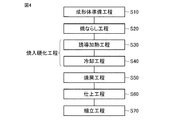
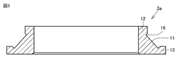
図4を参照して、本実施の形態における内輪の製造方法では、まず工程(S10)として成形体準備工程が実施される。この工程(S10)では、高周波焼入処理に適した任意の成分組成を有する鋼材が準備され、鍛造、旋削などの加工が実施されることにより、所望の内輪の形状に応じた形状を有する成形体が作製される。より具体的には、図5および図6に示すように、1000mm以上の内径を有する内輪の形状に応じた成形体が作製される。 Referring to FIG. 4, in the inner ring manufacturing method according to the present embodiment, a molded body preparation step is first performed as a step (S <b> 10). In this step (S10), a steel material having an arbitrary component composition suitable for induction hardening is prepared, and by performing processing such as forging and turning, forming having a shape corresponding to the shape of a desired inner ring. A body is made. More specifically, as shown in FIGS. 5 and 6, a molded body corresponding to the shape of the inner ring having an inner diameter of 1000 mm or more is produced.
図5および図6に示すように、成形体は鋼から構成され、底面が軌道輪の転走面11となるべき環状の溝19が外周面に形成されている。また、成形体においては、溝19に隣接する領域が軌道輪(内輪部材3b)の外周表面となるべき点線14で示す位置より外側に延在する余肉部12、13を含む。ここで、成形体の中心軸に沿った方向における余肉部12の厚みは、たとえば1mm以上5mm以下とすることができる。また、成形体の中心軸に対して垂直な径方向における余肉部13の厚みは、たとえば1mm以上5mm以下とすることができる。
As shown in FIGS. 5 and 6, the compact is made of steel, and an
次に、工程(S20)として、焼ならし工程が実施される。この工程(S20)では、工程(S10)において作製された成形体がA1変態点以上の温度に加熱された後、A1変態点未満の温度に冷却されることにより焼ならし処理が実施される。このとき、焼ならし処理の冷却時における冷却速度は、成形体を構成する鋼がマルテンサイトに変態しない冷却速度、すなわち臨界冷却速度未満の冷却速度であればよい。そして、焼ならし処理後の成形体の硬度は、この冷却速度が大きくなると高く、冷却速度が小さくなると低くなる。そのため、当該冷却速度を調整することにより、所望の硬度を成形体に付与することができる。 Next, a normalizing step is performed as a step (S20). In this step (S20), after the fabricated molded body is heated to a temperature not lower than the A 1 transformation point in the step (S10), the normalizing process by being cooled to a temperature below the A 1 transformation point implementation Is done. At this time, the cooling rate at the time of cooling in the normalizing process may be a cooling rate at which the steel constituting the formed body is not transformed into martensite, that is, a cooling rate lower than the critical cooling rate. The hardness of the molded body after the normalizing treatment is high when the cooling rate is large, and is low when the cooling rate is small. Therefore, desired hardness can be imparted to the molded body by adjusting the cooling rate.
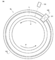
次に、図4を参照して、焼入硬化工程が実施される。この焼入硬化工程は、工程(S30)として実施される誘導加熱工程と、工程(S40)として実施される冷却工程とを含んでいる。工程(S30)では、図7および図8を参照して、誘導加熱コイルとしてのコイル121が、成形体において転動体が転走すべき面である転走面11(環状領域)の一部に面するように配置される。なお、コイル121の形状は任意の形状とすることができる。
Next, referring to FIG. 4, a quench hardening process is performed. This quench hardening process includes an induction heating process performed as the process (S30) and a cooling process performed as the process (S40). In the step (S30), referring to FIG. 7 and FIG. 8, the
次に、成形体が中心軸周り、具体的には矢印αの向きに回転されるとともに、コイル121に対して電源(図示しない)から高周波電流が供給される。これにより、成形体の転走面11を含む表層領域がA1点以上の温度に誘導加熱され、転走面11に沿った円環状の加熱領域が形成される。このとき、転走面11の表面の温度は、放射温度計などの温度計122により測定され、管理される。
Next, the compact is rotated around the central axis, specifically in the direction of the arrow α, and a high frequency current is supplied to the
次に、工程(S40)においては、工程(S30)において形成された加熱領域を含む成形体全体に対して、たとえば冷却液としての水が噴射されることにより、加熱領域全体がMS点以下の温度に同時に冷却される。これにより、加熱領域がマルテンサイトに変態し、転走面11を含む領域が硬化する。以上の手順により、高周波焼入が実施され、焼入硬化工程が完了する。
Next, in the step (S40), for example, water as a cooling liquid is sprayed on the entire formed body including the heating region formed in the step (S30), so that the entire heating region is equal to or lower than the MS point. At the same time to be cooled. Thereby, a heating area | region transforms into a martensite and the area | region containing the rolling
次に、工程(S50)として焼戻工程が実施される。この工程(S50)では、工程(S30)および(S40)において焼入硬化された成形体が、たとえば炉内に装入され、A1点以下の温度に加熱されて所定の時間保持されることにより、焼戻処理が実施される。 Next, a tempering step is performed as a step (S50). In this step (S50), the molded body quenched and hardened in steps (S30) and (S40) is charged into, for example, a furnace, heated to a temperature of A 1 point or less, and held for a predetermined time. Thus, the tempering process is performed.
次に、工程(S60)として仕上工程が実施される。この工程(S60)では、図9に示すように成形体の余肉部12、13を除去することで内輪部材3aの形状を整えるとともに、その他の必要な加工、たとえば転走面11に対する研磨加工などの仕上げ加工が実施される。以上のプロセスにより、複列円すいころ軸受の内輪を構成する内輪部材3aが完成する。内輪部材3aは、1000mm以上の内径を有し、高周波焼入によって焼入硬化層が転走面11に沿って全周にわたって均質に形成されている。
Next, a finishing step is performed as a step (S60). In this step (S60), the shape of the
また、内輪部材3aは、上述のように熱処理後に余肉部12、13を除去することによって内輪部材3aの外周表面16において溝19と隣接する領域(図9では、外周表面16において溝19から見て内輪部材3aの中心軸寄りに位置する領域)に硬化領域15と非硬化領域18とが露出する。したがって、内輪部材3aの外周表面16において、硬化領域15と非硬化領域18とが形成されていることを検出することで、当該内輪部材3aが上述した本開示に係る軌道輪の製造方法を用いて製造されたものであるか否かを容易に検知することができる。外周表面16において溝19と隣接する領域に硬化領域15と非硬化領域18とが形成されていることを検出する方法は、硬度測定など従来周知の任意の方法を用いることができる。ここで、外周表面16における硬化領域15の幅、つまり溝19の開口端部から硬化領域15の端部までの距離は1mm以上10mm以下とすることができる。また、図9では外周表面16において溝19から見て内輪部材3aの中心軸寄りに位置する領域だけに、硬化領域15と非硬化領域18との両方が形成されており、外周表面16において溝19から見て外周側に位置する領域には硬化領域15だけが露出している。しかし、本開示においては、外周表面16において、硬化領域15と非硬化領域18との両方が露出するのは、溝19からみて内輪部材3aの外周側の領域のみであってもよいし、溝19から見て外周側の領域および上記中心軸寄りに位置する領域の両方であってもよい。
Further, the
なお、上述のように熱処理を実施するときに余肉部12、13(図9参照)を形成しなかった場合には、図10に示すように内輪部材3aにおいて外輪2(図2参照)と対向する面である外周表面16の全面に硬化領域15が形成される。これは、余肉部12、13が存在しないため内輪部材3aの外周表面16の全体が誘導加熱により加熱されるためである。
When the
さらに、工程(S70)として組立工程が実施される。この工程(S70)では、上述のように作製された内輪部材3aと、上記内輪部材3aと同様に作製された内輪部材3bおよび外輪2とが、別途準備された転動体としてのころ6(図2参照)、保持器7(図2参照)、内輪間座4(図2参照)などと組み合わされることにより、図1および図2に示したような複列円すいころ軸受1が組み立てられる。以上の手順により、本実施の形態における複列円すいころ軸受の製造方法は完了する。また、異なる観点から言えば、図1および図2に示した複列円すいころ軸受1の製造方法は、軌道輪(図2に示す外輪2、内輪部材3a、3b、内輪間座4)を準備する工程と、円すい形状のころ6を準備する工程と、軌道輪ところとを組み合わせて複列円すいころ軸受1を組立てる工程とを備える。軌道輪(内輪部材3a、3b)は上述した軌道輪の製造方法により製造される。
Furthermore, an assembly process is performed as a process (S70). In this step (S70), the
本実施の形態では、工程(S30)において、成形体の転走面11の一部に面するように配置されたコイル121を周方向に沿って相対的に回転させることにより、成形体に加熱領域が形成される。そのため、成形体の外形形状に対して小さいコイル121を採用することが可能となっており、大型の成形体を焼入硬化する場合でも、焼入装置の製作コストを抑制することができる。また、本実施の形態では、加熱領域全体がMS点以下の温度に同時に冷却される。そのため、周方向に均質な環状の焼入硬化領域である硬化領域15を形成することが可能となり、一部の領域に残留応力が集中することが抑制される。
In the present embodiment, in the step (S30), the molded body is heated by relatively rotating the
なお、工程(S30)においては、誘導加熱によって成形体を加熱することができれば、任意の形状のコイル121を適用することができる。たとえば、成形体における転走面11の全体を覆うような環状のコイルを用いてもよい。
In the step (S30), the
なお、上記工程(S20)として実施される焼きならし工程は、本発明の軌道輪の製造方法において必須の工程ではないが、これを実施することにより焼割れの発生を抑制しつつ、鋼からなる成形体の硬度を調整することができる。 In addition, the normalizing process implemented as said process (S20) is not an essential process in the manufacturing method of the bearing ring of this invention, However, By implementing this, it suppresses generation | occurrence | production of a burning crack, From steel. The hardness of the resulting molded body can be adjusted.
この工程(S20)では、成形体に気体とともに硬質の粒子が吹き付けられることにより、成形体が冷却されつつショットブラスト処理が実施されてもよい。これにより、焼ならし処理の際の衝風冷却と同時にショットブラスト処理を実施することができるため、成形体の表層部に生成したスケールが除去され、スケールの生成に起因した内輪部材3aの特性低下やスケールの生成による熱伝導率の低下が抑制される。ここで、硬質の粒子(投射材)としては、たとえば鋼や鋳鉄などからなる金属製の粒子を採用することができる。
In this step (S20), the shot blasting process may be performed while the molded body is cooled by spraying hard particles together with gas on the molded body. Thereby, since the shot blast process can be performed simultaneously with the blast cooling during the normalizing process, the scale generated in the surface layer portion of the molded body is removed, and the characteristics of the
<上記製造方法の作用効果>
図4〜図9に示した本開示に係る軌道輪の製造方法は、複列円すいころ軸受の軌道輪の製造方法であって、上述のように成形体を準備する工程(S10)と、加熱領域を形成する工程(S30)と、冷却する工程(S40)と、除去する工程(S60)とを備える。成形体を準備する工程(S10)では、鋼から構成され、底面が軌道輪の転走面11となるべき環状の溝19が外周面に形成された成形体を準備する。加熱領域を形成する工程(S30)では、成形体を誘導加熱することにより、溝19の底面を含み、A1点以上の温度に加熱された加熱領域を形成する。冷却する工程(S40)では、加熱領域全体をMs点以下の温度に同時に冷却する。成形体を準備する工程(S10)では、成形体において溝19に隣接する領域が軌道輪の外周表面となるべき位置より外側に延在する余肉部12、13を含む。除去する工程(S60)では、冷却する工程(S40)の後、成形体から余肉部12、13を除去する。
<Operation effect of the above manufacturing method>
The method for manufacturing a bearing ring according to the present disclosure illustrated in FIGS. 4 to 9 is a method for manufacturing a bearing ring of a double row tapered roller bearing, and includes a step of preparing a molded body as described above (S10), and heating. A step of forming a region (S30), a step of cooling (S40), and a step of removing (S60) are provided. In the step of preparing the formed body (S10), a formed body is prepared which is made of steel and has a bottom surface formed with an
このよにすれば、誘導加熱によって軌道輪を構成する内輪部材3aの転走面11となるべき溝19の底面を含む加熱領域に選択的に焼入れ処理を行うことができるので、防浸炭処理を伴った浸炭熱処理を行う場合より軌道輪の製造工程を簡略化できるとともに、工程に要する時間も短縮できる。このため、軌道輪の製造コストを低減することができる。
According to this configuration, it is possible to selectively quench the heating region including the bottom surface of the
また、加熱対象となっている溝19に隣接して余肉部12、13が存在する状態で焼入れ処理を行うので、余肉部12、13が無い場合における溝19の開口端部、つまり溝19の内周面と軌道輪としての内輪部材3aの外周表面との接続部(角部)が過加熱あるいは過冷却されることで当該部分に焼割れなどの不具合が発生する可能性を低減できる。つまり、上述した余肉部12、13が形成されていることで、加熱領域を形成する工程(S30)や冷却する工程(S40)における溝19の周囲での加熱状態や冷却状態を均一化することができる。異なる観点から言えば、当該余肉部12、13を形成することにより、溝19の周囲における質量効果による焼入れのむらの発生を抑制できる。
Further, since the quenching process is performed in a state where the
上記軌道輪の製造方法において、図7などに示すように成形体は環状の形状を有していてもよい。成形体を準備する工程(S10)において、成形体の余肉部12、13は、成形体の中心軸方向において溝19を挟むように環状に配置されていてもよい。この場合、溝19の全周に隣接するように余肉部12、13を配置することになるので、溝19全体について焼入れのむらの発生を抑制することができる。
In the method for manufacturing a race, the molded body may have an annular shape as shown in FIG. In the step of preparing the molded body (S10), the
上記軌道輪の製造方法では、成形体を準備する工程(S10)において、成形体の溝19の底面が中心軸となす角度θ(図2参照)は40°以上50°以下であってもよい。この場合、上記角度θが上述のような数値範囲となる、いわゆる急勾配複列円すいころ軸受の軌道輪(内輪部材3a)においては、当該軌道輪の外周表面において溝19と隣接する部分と溝19の底面に連なる部分とで焼入れ処理時の加熱状態や冷却状態に差が発生し易い。そのため、本開示に係る軌道輪の製造方法が特に有効である。
In the method for manufacturing a bearing ring, in the step of preparing a molded body (S10), an angle θ (see FIG. 2) formed by the bottom surface of the
図1および図2に示した複列円すいころ軸受の製造方法は、軌道輪を準備する工程と、円すい形状のころを準備する工程と、軌道輪ところとを組み合わせて複列円すいころ軸受を組立てる工程とを備える。軌道輪を構成する内輪部材3a、3bは上記軌道輪の製造方法により製造される。このようにすれば、焼割れなどの不具合を発生させることなく、かつ製造コストの増大を招くことなく、十分な特性の内輪部材3a、3bを備えた複列円すいころ軸受1を得ることができる。
The double row tapered roller bearing manufacturing method shown in FIG. 1 and FIG. 2 assembles a double row tapered roller bearing by combining the step of preparing the race ring, the step of preparing the tapered roller, and the race ring place. A process. The
以上のように本発明の実施の形態について説明を行ったが、上述の実施の形態を様々に変形することも可能である。また、本発明の範囲は上述の実施の形態に限定されるものではない。本発明の範囲は、特許請求の範囲によって示され、特許請求の範囲と均等の意味および範囲内でのすべての変更を含むことが意図される。 Although the embodiment of the present invention has been described above, the above-described embodiment can be variously modified. The scope of the present invention is not limited to the above-described embodiment. The scope of the present invention is defined by the terms of the claims, and is intended to include any modifications within the scope and meaning equivalent to the terms of the claims.
本実施形態は、風力発電装置に適用される複列円すいころ軸受に特に有利に適用される。 This embodiment is particularly advantageously applied to a double-row tapered roller bearing applied to a wind power generator.
1 軸受、2 外輪、3a,3b 内輪部材、4 内輪間座、5 内輪、6 ころ、7 保持器、8 ボルト用孔、9 転走面、10 風力発電装置、11 転走面、12,13 余肉部、14 点線、15 硬化領域、16 外周表面、17 境界部、18 非硬化領域、19 溝、20 ロータヘッド、22 主軸、25 中心軸、30 ブレード、40 増速機、50 発電機、60 主軸受、61 出力軸、90 ナセル、100 タワー、121 コイル、122 温度計。
DESCRIPTION OF
Claims (6)
前記外輪の内周側に配置され、環状の形状を有する軌道輪である内輪とを備え、
前記内輪には前記外輪と対向する外周表面に、底面が転走面となる溝が2列形成され、さらに、
前記内輪の前記転走面と接するように前記溝の内部に配置されるとともに、前記外輪と接する円すい形状のころを備え、
前記内輪の前記外周表面において、前記溝と隣接する領域は、前記溝の内周面から前記領域にまで延在する硬化領域と、前記硬化領域より前記溝から離れた位置に配置されるとともに前記硬化領域より硬度の低い非硬化領域とを含む、複列円すいころ軸受。 An outer ring that is an orbital ring having an annular shape;
An inner ring that is disposed on the inner peripheral side of the outer ring and is a race ring having an annular shape;
In the inner ring, two rows of grooves whose bottom surface is a rolling surface are formed on the outer peripheral surface facing the outer ring,
It is arranged inside the groove so as to be in contact with the rolling surface of the inner ring, and comprises a conical roller in contact with the outer ring,
In the outer peripheral surface of the inner ring, the region adjacent to the groove is disposed in a hardened region extending from the inner peripheral surface of the groove to the region, and at a position farther from the groove than the hardened region. Double-row tapered roller bearing including a non-cured region having a lower hardness than the cured region
鋼から構成され、底面が前記軌道輪の転走面となるべき環状の溝が外周面に形成された成形体を準備する工程と、
前記成形体を誘導加熱することにより、前記溝の前記底面を含み、A1点以上の温度に加熱された加熱領域を形成する工程と、
前記加熱領域全体をMs点以下の温度に同時に冷却する工程とを備え、
前記成形体を準備する工程では、前記成形体において前記溝に隣接する領域が前記軌道輪の外周表面となるべき位置より外側に延在する余肉部を含み、さらに、
前記冷却する工程の後、前記成形体から前記余肉部を除去する工程を備える、軌道輪の製造方法。 A method of manufacturing a raceway for a double row tapered roller bearing,
Preparing a molded body made of steel and having a bottom surface formed with an annular groove on the outer peripheral surface to be a rolling surface of the raceway;
Forming the heated region including the bottom surface of the groove and heated to a temperature of A 1 point or more by induction heating the molded body;
Simultaneously cooling the entire heating area to a temperature below the M s point,
In the step of preparing the formed body, the region adjacent to the groove in the formed body includes a surplus portion extending outward from a position to be the outer peripheral surface of the raceway,
A method for manufacturing a race, comprising a step of removing the surplus portion from the molded body after the cooling step.
前記成形体を準備する工程において、前記成形体の前記余肉部は、前記成形体の中心軸方向において前記溝を挟むように環状に配置されている、請求項3に記載の軌道輪の製造方法。 The molded body has an annular shape,
The track ring manufacturing according to claim 3, wherein in the step of preparing the molded body, the surplus portion of the molded body is arranged in an annular shape so as to sandwich the groove in a central axis direction of the molded body. Method.
円すい形状のころを準備する工程と、
前記軌道輪と前記ころとを組み合わせて複列円すいころ軸受を組立てる工程とを備え、
前記軌道輪は請求項3〜5のいずれか1項に記載の軌道輪の製造方法により製造される、複列円すいころ軸受の製造方法。 A process of preparing a bearing ring;
Preparing a cone-shaped roller;
A step of assembling a double row tapered roller bearing by combining the raceway and the roller,
The said ring is a manufacturing method of the double row tapered roller bearing manufactured by the manufacturing method of the bearing ring of any one of Claims 3-5.
Priority Applications (5)
| Application Number | Priority Date | Filing Date | Title |
|---|---|---|---|
| JP2015213092A JP2017082945A (en) | 2015-10-29 | 2015-10-29 | Double row tapered roller bearing, race ring and method of manufacturing double row tapered roller bearing |
| PCT/JP2016/080240 WO2017073327A1 (en) | 2015-10-29 | 2016-10-12 | Multi-row tapered roller bearing, and method for manufacturing bearing ring and multi-row tapered roller bearing |
| CN201680062825.3A CN108368877A (en) | 2015-10-29 | 2016-10-12 | Double-row conical bearing, bearer ring and the method for producing double-row conical bearing |
| US15/771,723 US10378076B2 (en) | 2015-10-29 | 2016-10-12 | Double row tapered roller bearing, bearing ring, and method for producing double row tapered roller bearing |
| EP16859563.5A EP3369950A4 (en) | 2015-10-29 | 2016-10-12 | Multi-row tapered roller bearing, and method for manufacturing bearing ring and multi-row tapered roller bearing |
Applications Claiming Priority (1)
| Application Number | Priority Date | Filing Date | Title |
|---|---|---|---|
| JP2015213092A JP2017082945A (en) | 2015-10-29 | 2015-10-29 | Double row tapered roller bearing, race ring and method of manufacturing double row tapered roller bearing |
Publications (2)
| Publication Number | Publication Date |
|---|---|
| JP2017082945A true JP2017082945A (en) | 2017-05-18 |
| JP2017082945A5 JP2017082945A5 (en) | 2018-11-08 |
Family
ID=58630254
Family Applications (1)
| Application Number | Title | Priority Date | Filing Date |
|---|---|---|---|
| JP2015213092A Pending JP2017082945A (en) | 2015-10-29 | 2015-10-29 | Double row tapered roller bearing, race ring and method of manufacturing double row tapered roller bearing |
Country Status (5)
| Country | Link |
|---|---|
| US (1) | US10378076B2 (en) |
| EP (1) | EP3369950A4 (en) |
| JP (1) | JP2017082945A (en) |
| CN (1) | CN108368877A (en) |
| WO (1) | WO2017073327A1 (en) |
Cited By (1)
| Publication number | Priority date | Publication date | Assignee | Title |
|---|---|---|---|---|
| CN108412894A (en) * | 2018-03-15 | 2018-08-17 | 南昌工程学院 | A kind of novel magnetic fluid bearing and its manufacturing method |
Citations (7)
| Publication number | Priority date | Publication date | Assignee | Title |
|---|---|---|---|---|
| JP2006009891A (en) * | 2004-06-24 | 2006-01-12 | Nsk Ltd | Roller bearing |
| JP2007024294A (en) * | 2005-07-21 | 2007-02-01 | Ntn Corp | Tapered roller bearing and spindle supporting structure of wind power generator |
| JP2008064244A (en) * | 2006-09-08 | 2008-03-21 | Ntn Corp | Spindle supporting structure for wind power generator |
| JP2009019713A (en) * | 2007-07-12 | 2009-01-29 | Nsk Ltd | Rolling bearing |
| JP2011117487A (en) * | 2009-12-01 | 2011-06-16 | Ntn Corp | Orbital ring and rolling bearing |
| CN204152957U (en) * | 2014-10-18 | 2015-02-11 | 湖州铧星轴承有限公司 | High loading elevator traction sheave special bearing |
| JP2015031343A (en) * | 2013-08-02 | 2015-02-16 | 日本精工株式会社 | Roller bearing, and roller bearing manufacturing method |
Family Cites Families (25)
| Publication number | Priority date | Publication date | Assignee | Title |
|---|---|---|---|---|
| US2274187A (en) * | 1941-09-26 | 1942-02-24 | Timken Roller Bearing Co | Roller bearing axle construction |
| JP2926240B2 (en) | 1989-05-02 | 1999-07-28 | 株式会社日立製作所 | Sliding material and surface treatment method |
| US5861067A (en) * | 1995-08-08 | 1999-01-19 | The Timken Company | Steel machine component having refined surface microstructure and process for forming the same |
| US6224266B1 (en) * | 1998-09-18 | 2001-05-01 | Ntn Corporation | Wheel bearing device |
| JP2000211310A (en) * | 1999-01-21 | 2000-08-02 | Ntn Corp | Wheel support structure |
| DE60131043T2 (en) * | 2000-03-03 | 2008-10-30 | Jtekt Corp. | bearing device |
| DE10228333C1 (en) | 2002-06-26 | 2003-09-25 | Rothe Erde Gmbh | Hardening the race rim zone in production of bearing ring for large roller bearing involves heating with inductor at specified distance whilst rotating ring about axis, and then chilling |
| JP4268793B2 (en) * | 2002-10-29 | 2009-05-27 | 株式会社ジェイテクト | Method of manufacturing inner ring member for tapered roller bearing, inner ring member for tapered roller bearing, tapered roller bearing device for axle |
| JP4572644B2 (en) * | 2004-09-30 | 2010-11-04 | 日本精工株式会社 | Manufacturing method of high precision ring |
| EP1792672A4 (en) | 2004-09-22 | 2008-10-29 | Nsk Ltd | Raceway ring for radial ball bearing, method of producing the raceway ring, and method and device for producing high precision ring |
| JP2006291247A (en) * | 2005-04-06 | 2006-10-26 | Ntn Corp | Heat treatment method, method for producing thin member for bearing, thin member for bearing and thrust bearing |
| KR100752510B1 (en) | 2006-04-14 | 2007-08-29 | 유니슨 주식회사 | Wind energy converter with single main bearing |
| DK2060806T3 (en) | 2006-09-08 | 2014-04-28 | Ntn Toyo Bearing Co Ltd | Roll bearing and main shaft support structure for a wind turbine |
| WO2008059617A1 (en) * | 2006-11-14 | 2008-05-22 | Ntn Corporation | Bearing device for wheel |
| CN101215670A (en) * | 2007-01-04 | 2008-07-09 | 江苏省交通工程有限公司 | Ship lock mushroom head, mushroom head cap and processing method thereof |
| EP2746411A3 (en) * | 2007-11-12 | 2014-10-15 | Topy Kogyo Kabushiki Kaisha | Method for heat treatment of columnar work |
| JP5045461B2 (en) * | 2008-01-30 | 2012-10-10 | 株式会社ジェイテクト | Hub unit for vehicles |
| JP2009197137A (en) * | 2008-02-21 | 2009-09-03 | Nsk Ltd | Material for plastic retainer, plastic retainer for ball-and-roller bearing, and ball-and-roller bearing |
| JP5183358B2 (en) * | 2008-08-22 | 2013-04-17 | Ntn株式会社 | Wheel bearing device |
| CN104694729A (en) | 2009-07-22 | 2015-06-10 | Ntn株式会社 | Method for heat-treating a ring-shaped member, method for producing a ring-shaped member, ring-shaped member, bearing ring, rolling bearing, and method for producing a bearing ring |
| JP5560090B2 (en) * | 2010-05-17 | 2014-07-23 | Ntn株式会社 | Wheel bearing device |
| US9487843B2 (en) | 2011-01-21 | 2016-11-08 | Ntn Corporation | Method for producing a bearing ring |
| DK2495466T5 (en) * | 2011-12-22 | 2014-07-21 | Imo Holding Gmbh | Roller bearing assembly with sloping curing zones |
| CN104232874A (en) * | 2013-06-16 | 2014-12-24 | 天津市正瀚石油设备制造有限公司 | Method for quenching slip inserts |
| WO2014209982A1 (en) * | 2013-06-26 | 2014-12-31 | The Timken Company | Double row tapered roller thrust bearing for improved loading capacity |
-
2015
- 2015-10-29 JP JP2015213092A patent/JP2017082945A/en active Pending
-
2016
- 2016-10-12 CN CN201680062825.3A patent/CN108368877A/en active Pending
- 2016-10-12 US US15/771,723 patent/US10378076B2/en not_active Expired - Fee Related
- 2016-10-12 WO PCT/JP2016/080240 patent/WO2017073327A1/en active Application Filing
- 2016-10-12 EP EP16859563.5A patent/EP3369950A4/en not_active Withdrawn
Patent Citations (7)
| Publication number | Priority date | Publication date | Assignee | Title |
|---|---|---|---|---|
| JP2006009891A (en) * | 2004-06-24 | 2006-01-12 | Nsk Ltd | Roller bearing |
| JP2007024294A (en) * | 2005-07-21 | 2007-02-01 | Ntn Corp | Tapered roller bearing and spindle supporting structure of wind power generator |
| JP2008064244A (en) * | 2006-09-08 | 2008-03-21 | Ntn Corp | Spindle supporting structure for wind power generator |
| JP2009019713A (en) * | 2007-07-12 | 2009-01-29 | Nsk Ltd | Rolling bearing |
| JP2011117487A (en) * | 2009-12-01 | 2011-06-16 | Ntn Corp | Orbital ring and rolling bearing |
| JP2015031343A (en) * | 2013-08-02 | 2015-02-16 | 日本精工株式会社 | Roller bearing, and roller bearing manufacturing method |
| CN204152957U (en) * | 2014-10-18 | 2015-02-11 | 湖州铧星轴承有限公司 | High loading elevator traction sheave special bearing |
Cited By (2)
| Publication number | Priority date | Publication date | Assignee | Title |
|---|---|---|---|---|
| CN108412894A (en) * | 2018-03-15 | 2018-08-17 | 南昌工程学院 | A kind of novel magnetic fluid bearing and its manufacturing method |
| CN108412894B (en) * | 2018-03-15 | 2019-09-17 | 南昌工程学院 | A kind of novel magnetic fluid bearing and its manufacturing method |
Also Published As
| Publication number | Publication date |
|---|---|
| US10378076B2 (en) | 2019-08-13 |
| EP3369950A1 (en) | 2018-09-05 |
| WO2017073327A1 (en) | 2017-05-04 |
| CN108368877A (en) | 2018-08-03 |
| EP3369950A4 (en) | 2019-03-27 |
| US20180347005A1 (en) | 2018-12-06 |
Similar Documents
| Publication | Publication Date | Title |
|---|---|---|
| JP5665564B2 (en) | Manufacturing method of bearing ring | |
| JP2011117016A (en) | Method for manufacturing bearing ring, bearing ring and rolling bearing | |
| WO2017073325A1 (en) | Method for manufacturing bearing ring, and multi-row tapered roller bearing and manufacturing method therefor | |
| JP5557235B2 (en) | Heat treatment method for ring-shaped member, method for manufacturing ring-shaped member | |
| JP2015180783A (en) | Bearing ring and method of producing rolling bearing | |
| JP6023493B2 (en) | Method of manufacturing bearing ring, bearing ring and rolling bearing | |
| WO2017203915A1 (en) | Heat treatment method for ring-shaped member, manufacturing method for ring-shaped member, bearing ring of roller bearing, and roller bearing | |
| JP5773349B2 (en) | Method of manufacturing bearing ring and rolling bearing | |
| JP5455031B2 (en) | Manufacturing method of bearing ring and manufacturing method of rolling bearing | |
| JP5534403B2 (en) | Bearing rings and rolling bearings | |
| WO2017073327A1 (en) | Multi-row tapered roller bearing, and method for manufacturing bearing ring and multi-row tapered roller bearing | |
| JP2014095154A (en) | Heat treatment method for ring-shaped member, method for producing ring-shaped member, ring-shaped member, bearing ring of rolling bearing, and rolling bearing | |
| JP2017082300A (en) | Manufacturing method of bearing ring and double row tapered roller bearing | |
| JP2015193936A (en) | Bearing ring and method of producing rolling bearing | |
| WO2017073326A1 (en) | Method for manufacturing bearing ring and method for manufacturing multi-row tapered roller bearing | |
| JP2015187310A (en) | Bearing ring production method, bearing ring, and rolling bearing | |
| JP6178365B2 (en) | Manufacturing method of bearing ring, cylindrical roller bearing and tapered roller bearing | |
| JP6072145B2 (en) | Manufacturing method of bearing ring | |
| JP2017082943A (en) | Process of manufacture of bearing ring and process of manufacture of double row conical roller bearing | |
| JP2014025097A (en) | Method for manufacturing bearing ring, bearing ring and rolling bearing | |
| WO2017199872A1 (en) | Method for heat-treating ring-shaped member, method for manufacturing ring-shaped member, raceway of rolling bearing, and rolling bearing | |
| JP5721449B2 (en) | Bearing rings and rolling bearings | |
| JP5665565B2 (en) | Manufacturing method of bearing ring | |
| JP2015187311A (en) | Bearing ring production method, bearing ring, and rolling bearing |
Legal Events
| Date | Code | Title | Description |
|---|---|---|---|
| A521 | Request for written amendment filed |
Free format text: JAPANESE INTERMEDIATE CODE: A523 Effective date: 20180927 |
|
| A621 | Written request for application examination |
Free format text: JAPANESE INTERMEDIATE CODE: A621 Effective date: 20180927 |
|
| A131 | Notification of reasons for refusal |
Free format text: JAPANESE INTERMEDIATE CODE: A131 Effective date: 20190611 |
|
| A521 | Request for written amendment filed |
Free format text: JAPANESE INTERMEDIATE CODE: A523 Effective date: 20190719 |
|
| A02 | Decision of refusal |
Free format text: JAPANESE INTERMEDIATE CODE: A02 Effective date: 20191203 |