JP5045461B2 - Hub unit for vehicles - Google Patents
Hub unit for vehicles Download PDFInfo
- Publication number
- JP5045461B2 JP5045461B2 JP2008018717A JP2008018717A JP5045461B2 JP 5045461 B2 JP5045461 B2 JP 5045461B2 JP 2008018717 A JP2008018717 A JP 2008018717A JP 2008018717 A JP2008018717 A JP 2008018717A JP 5045461 B2 JP5045461 B2 JP 5045461B2
- Authority
- JP
- Japan
- Prior art keywords
- hardened layer
- outer ring
- hub unit
- ring raceway
- raceway
- Prior art date
- Legal status (The legal status is an assumption and is not a legal conclusion. Google has not performed a legal analysis and makes no representation as to the accuracy of the status listed.)
- Expired - Fee Related
Links
Images

Classifications
-
- F—MECHANICAL ENGINEERING; LIGHTING; HEATING; WEAPONS; BLASTING
- F16—ENGINEERING ELEMENTS AND UNITS; GENERAL MEASURES FOR PRODUCING AND MAINTAINING EFFECTIVE FUNCTIONING OF MACHINES OR INSTALLATIONS; THERMAL INSULATION IN GENERAL
- F16C—SHAFTS; FLEXIBLE SHAFTS; ELEMENTS OR CRANKSHAFT MECHANISMS; ROTARY BODIES OTHER THAN GEARING ELEMENTS; BEARINGS
- F16C33/00—Parts of bearings; Special methods for making bearings or parts thereof
- F16C33/30—Parts of ball or roller bearings
- F16C33/58—Raceways; Race rings
- F16C33/64—Special methods of manufacture
-
- F—MECHANICAL ENGINEERING; LIGHTING; HEATING; WEAPONS; BLASTING
- F16—ENGINEERING ELEMENTS AND UNITS; GENERAL MEASURES FOR PRODUCING AND MAINTAINING EFFECTIVE FUNCTIONING OF MACHINES OR INSTALLATIONS; THERMAL INSULATION IN GENERAL
- F16C—SHAFTS; FLEXIBLE SHAFTS; ELEMENTS OR CRANKSHAFT MECHANISMS; ROTARY BODIES OTHER THAN GEARING ELEMENTS; BEARINGS
- F16C19/00—Bearings with rolling contact, for exclusively rotary movement
- F16C19/22—Bearings with rolling contact, for exclusively rotary movement with bearing rollers essentially of the same size in one or more circular rows, e.g. needle bearings
- F16C19/34—Bearings with rolling contact, for exclusively rotary movement with bearing rollers essentially of the same size in one or more circular rows, e.g. needle bearings for both radial and axial load
- F16C19/38—Bearings with rolling contact, for exclusively rotary movement with bearing rollers essentially of the same size in one or more circular rows, e.g. needle bearings for both radial and axial load with two or more rows of rollers
- F16C19/383—Bearings with rolling contact, for exclusively rotary movement with bearing rollers essentially of the same size in one or more circular rows, e.g. needle bearings for both radial and axial load with two or more rows of rollers with tapered rollers, i.e. rollers having essentially the shape of a truncated cone
- F16C19/385—Bearings with rolling contact, for exclusively rotary movement with bearing rollers essentially of the same size in one or more circular rows, e.g. needle bearings for both radial and axial load with two or more rows of rollers with tapered rollers, i.e. rollers having essentially the shape of a truncated cone with two rows, i.e. double-row tapered roller bearings
- F16C19/386—Bearings with rolling contact, for exclusively rotary movement with bearing rollers essentially of the same size in one or more circular rows, e.g. needle bearings for both radial and axial load with two or more rows of rollers with tapered rollers, i.e. rollers having essentially the shape of a truncated cone with two rows, i.e. double-row tapered roller bearings in O-arrangement
-
- F—MECHANICAL ENGINEERING; LIGHTING; HEATING; WEAPONS; BLASTING
- F16—ENGINEERING ELEMENTS AND UNITS; GENERAL MEASURES FOR PRODUCING AND MAINTAINING EFFECTIVE FUNCTIONING OF MACHINES OR INSTALLATIONS; THERMAL INSULATION IN GENERAL
- F16C—SHAFTS; FLEXIBLE SHAFTS; ELEMENTS OR CRANKSHAFT MECHANISMS; ROTARY BODIES OTHER THAN GEARING ELEMENTS; BEARINGS
- F16C33/00—Parts of bearings; Special methods for making bearings or parts thereof
- F16C33/30—Parts of ball or roller bearings
- F16C33/58—Raceways; Race rings
- F16C33/583—Details of specific parts of races
- F16C33/585—Details of specific parts of races of raceways, e.g. ribs to guide the rollers
-
- F—MECHANICAL ENGINEERING; LIGHTING; HEATING; WEAPONS; BLASTING
- F16—ENGINEERING ELEMENTS AND UNITS; GENERAL MEASURES FOR PRODUCING AND MAINTAINING EFFECTIVE FUNCTIONING OF MACHINES OR INSTALLATIONS; THERMAL INSULATION IN GENERAL
- F16C—SHAFTS; FLEXIBLE SHAFTS; ELEMENTS OR CRANKSHAFT MECHANISMS; ROTARY BODIES OTHER THAN GEARING ELEMENTS; BEARINGS
- F16C2240/00—Specified values or numerical ranges of parameters; Relations between them
- F16C2240/40—Linear dimensions, e.g. length, radius, thickness, gap
- F16C2240/60—Thickness, e.g. thickness of coatings
-
- F—MECHANICAL ENGINEERING; LIGHTING; HEATING; WEAPONS; BLASTING
- F16—ENGINEERING ELEMENTS AND UNITS; GENERAL MEASURES FOR PRODUCING AND MAINTAINING EFFECTIVE FUNCTIONING OF MACHINES OR INSTALLATIONS; THERMAL INSULATION IN GENERAL
- F16C—SHAFTS; FLEXIBLE SHAFTS; ELEMENTS OR CRANKSHAFT MECHANISMS; ROTARY BODIES OTHER THAN GEARING ELEMENTS; BEARINGS
- F16C2326/00—Articles relating to transporting
- F16C2326/01—Parts of vehicles in general
- F16C2326/02—Wheel hubs or castors
-
- F—MECHANICAL ENGINEERING; LIGHTING; HEATING; WEAPONS; BLASTING
- F16—ENGINEERING ELEMENTS AND UNITS; GENERAL MEASURES FOR PRODUCING AND MAINTAINING EFFECTIVE FUNCTIONING OF MACHINES OR INSTALLATIONS; THERMAL INSULATION IN GENERAL
- F16C—SHAFTS; FLEXIBLE SHAFTS; ELEMENTS OR CRANKSHAFT MECHANISMS; ROTARY BODIES OTHER THAN GEARING ELEMENTS; BEARINGS
- F16C33/00—Parts of bearings; Special methods for making bearings or parts thereof
- F16C33/30—Parts of ball or roller bearings
- F16C33/58—Raceways; Race rings
- F16C33/581—Raceways; Race rings integral with other parts, e.g. with housings or machine elements such as shafts or gear wheels
-
- Y—GENERAL TAGGING OF NEW TECHNOLOGICAL DEVELOPMENTS; GENERAL TAGGING OF CROSS-SECTIONAL TECHNOLOGIES SPANNING OVER SEVERAL SECTIONS OF THE IPC; TECHNICAL SUBJECTS COVERED BY FORMER USPC CROSS-REFERENCE ART COLLECTIONS [XRACs] AND DIGESTS
- Y10—TECHNICAL SUBJECTS COVERED BY FORMER USPC
- Y10T—TECHNICAL SUBJECTS COVERED BY FORMER US CLASSIFICATION
- Y10T29/00—Metal working
- Y10T29/49—Method of mechanical manufacture
- Y10T29/49636—Process for making bearing or component thereof
- Y10T29/49643—Rotary bearing
- Y10T29/49679—Anti-friction bearing or component thereof
- Y10T29/49682—Assembling of race and rolling anti-friction members
- Y10T29/49684—Assembling of race and rolling anti-friction members with race making
Landscapes
- Engineering & Computer Science (AREA)
- General Engineering & Computer Science (AREA)
- Mechanical Engineering (AREA)
- Manufacturing & Machinery (AREA)
- Rolling Contact Bearings (AREA)
Description
本発明は、車両用ハブユニットに関する。 The present invention relates to a vehicle hub unit.
従来より、自動車の車輪を懸架装置に対して回転自在に支持するものとして、ハブユニットが用いられている。このハブユニットは、外周面に内輪軌道を有する内方部材であるハブホイールと、内周面に外輪軌道を有する外方部材である外輪と、これらの内輪軌道と外輪軌道との間に転動自在に設けられた複数の転動体とを備えている。このハブホイールには、フランジ部が設けられており、タイヤのホイールやブレーキディスクなどが取り付けられる。 Conventionally, a hub unit has been used as a vehicle that rotatably supports a vehicle wheel with respect to a suspension device. This hub unit rolls between a hub wheel that is an inner member having an inner ring raceway on an outer peripheral surface, an outer ring that is an outer member having an outer ring raceway on an inner peripheral surface, and the inner ring raceway and the outer ring raceway. And a plurality of freely provided rolling elements. The hub wheel is provided with a flange portion to which a tire wheel, a brake disk, or the like is attached.
上記の内外輪軌道は、長期の使用によって、複数の転動体から繰り返し荷重を受け、転がり疲れが生じる。この転がり疲れによって、内外輪軌道にフレーキングが発生し、軸受の寿命となる。
そこで、軸受寿命を確保するべく、フランジ部が設けられたハブホイールの内輪軌道に、高周波焼き入れによる硬化層を形成したものが提案されている(例えば、特許文献1参照)。
The inner and outer ring raceways are subjected to repeated loads from a plurality of rolling elements due to long-term use, and rolling fatigue occurs. This rolling fatigue causes flaking on the inner and outer ring raceways, resulting in a bearing life.
Therefore, in order to ensure the bearing life, there has been proposed one in which a hardened layer is formed by induction hardening on the inner ring raceway of the hub wheel provided with the flange portion (see, for example, Patent Document 1).
しかしながら、特許文献1に記載のハブユニットでは、硬化層における所定深さでの硬さを確保するために、硬化層深さをより大きくする傾向があった。このため、高周波焼き入れに要する時間が長くなり、製品コストが上昇する要因となっていた。製品コストの上昇を防ぐには、硬化層深さをできるかぎり小さくすればよいが、硬化層深さが小さくなり過ぎると、軌道にフレーキングが発生し易くなり、軸受寿命の低下を招来する。つまり、軸受寿命を保持しつつ、製品コストを削減するのは非常に困難であった。 However, the hub unit described in Patent Document 1 has a tendency to increase the depth of the hardened layer in order to ensure hardness at a predetermined depth in the hardened layer. For this reason, the time required for induction hardening becomes long, which has been a factor in increasing the product cost. In order to prevent an increase in product cost, the hardened layer depth should be made as small as possible. However, if the hardened layer depth becomes too small, flaking tends to occur on the raceway, leading to a reduction in bearing life. That is, it has been very difficult to reduce the product cost while maintaining the bearing life.
本発明は、上記問題点に鑑みてなされたものであり、軸受寿命を保持しつつ、製品コストを削減することができる車両用ハブユニットを提供することを目的とする。 The present invention has been made in view of the above problems, and an object of the present invention is to provide a vehicle hub unit that can reduce the product cost while maintaining the bearing life.
本発明は、外周面に内輪軌道を有する内方部材と、内周面に外輪軌道を有する外方部材と、これらの内輪軌道と外輪軌道との間に転動自在に設けられた複数の転動体とを備えている車両用ハブユニットにおいて、前記内輪軌道または外輪軌道の少なくとも一方の転がり接触域に、高周波焼き入れによる硬化層が形成され、その硬化層の軸方向両端部から1mm内方位置での硬化層深さが1.5〜1.9mmであることを特徴とする。
なお、ここでいう硬化層深さとは、軌道の軸方向所定位置において、軌道面に対して垂線を引き、その垂線上にある硬化層の底面と軌道面との間の距離をいう。また、転がり接触域とは、軌道が転動体と転がり接触し得る範囲をいう。
The present invention includes an inner member having an inner ring raceway on an outer peripheral surface, an outer member having an outer ring raceway on an inner peripheral surface, and a plurality of rolling elements provided between the inner ring raceway and the outer ring raceway. In a vehicle hub unit comprising a moving body, a hardened layer is formed by induction hardening in at least one rolling contact area of the inner ring raceway or the outer ring raceway, and the hardened layer is positioned 1 mm inward from both axial ends of the hardened layer. The depth of the hardened layer is 1.5 to 1.9 mm.
The term “hardened layer depth” as used herein refers to the distance between the bottom surface of the hardened layer and the raceway surface that is perpendicular to the raceway surface at a predetermined position in the axial direction of the raceway. Further, the rolling contact area refers to a range in which the track can be in rolling contact with the rolling elements.
上記の車両ハブユニットにおいて、硬化層深さが1.5mm未満では、硬化層深さが小さく、軌道にフレーキングが早期発生する。また、硬化層深さが1.9mmを超えると、高周波焼き入れに要する時間がより長くなる。すなわち、硬化層深さを1.5〜1.9mmとすることで、軌道にフレーキングが発生するのを抑制しつつ、高周波焼き入れに要する時間を短縮することができる。 In the above vehicle hub unit, when the hardened layer depth is less than 1.5 mm, the hardened layer depth is small, and flaking occurs early on the track. Moreover, when the hardened layer depth exceeds 1.9 mm, the time required for induction hardening becomes longer. That is, by setting the depth of the hardened layer to 1.5 to 1.9 mm, it is possible to reduce the time required for induction hardening while suppressing the occurrence of flaking on the track.
本発明によれば、軌道にフレーキングが発生するのを抑制しつつ、高周波焼き入れに要する時間を短縮することができるので、軸受寿命を保持しつつ、製品コストを削減することができる。 According to the present invention, it is possible to reduce the time required for induction hardening while suppressing the occurrence of flaking on the track, so that the product cost can be reduced while maintaining the bearing life.
以下、図面を参照しつつ、本発明の実施形態を説明する。
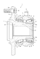
図1は、本発明の実施形態にかかるハブユニット1を示す部分断面図であり、図2は、外輪軌道を示す部分拡大図である。なお、図1の左右方向がハブユニット1の軸方向といい、図1の左側を軸方向外側、右側を軸方向内側という。
Hereinafter, embodiments of the present invention will be described with reference to the drawings.
FIG. 1 is a partial cross-sectional view showing a hub unit 1 according to an embodiment of the present invention, and FIG. 2 is a partially enlarged view showing an outer ring raceway. 1 is referred to as the axial direction of the hub unit 1, the left side in FIG. 1 is referred to as the axially outer side, and the right side is referred to as the axially inner side.
図1,2に示すように、このハブユニット1は、自動車の車輪を懸架装置に対して回転自在に支持するもので、外周面に一対の内輪軌道2a,2bを有する内方部材としてのハブホイール3と、内周面に一対の外輪軌道4a,4bを有する外方部材としての外輪5とを備えている。
As shown in FIGS. 1 and 2, the hub unit 1 supports a vehicle wheel rotatably with respect to a suspension device. A wheel 3 and an
また、ハブユニット1には、内輪軌道2a,2bと外輪軌道4a,4bとの間に転動自在に設けられた複数の転動体6と、複数の転動体6を周方向に所定の間隔で保持する保持器7とを備えている。上記ハブホイール3と外輪5との間に形成される環状空間には、当該環状空間を軸方向両端から封止するシール部材8が設けられている。
なお、図1に示したハブユニット1は、転動体6が円錐ころのものであるが、円錐ころの代わりに玉のものであってもよい。
Further, the hub unit 1 includes a plurality of
In the hub unit 1 shown in FIG. 1, the
上記外輪5は、例えば、炭素鋼(S55C)からなるもので、一対の外輪軌道4a,4bの転がり接触域には、高周波焼き入れによる硬化層Sが形成されている。
また、この外輪5には、操舵機構のナックル(図示せず)を固定するためのナックル用フランジ9が設けられている。このナックル用フランジ9は、外輪5の外周面から径外方向に延びるように設けられている。
なお、硬化層Sは、内輪軌道2a,2bのみに形成されてもよく、内輪軌道2a,2bと外輪軌道4a,4bとの両方に形成されてもよい。また、ここでいう転がり接触域とは、軌道が転動体と転がり接触し得る範囲をいう。
The
The
The hardened layer S may be formed only on the
ハブホイール3は、例えば、炭素鋼(S55C)で構成されたもので、円筒状の内輪部材10が外嵌された断面円筒状の小径部11と、小径部11から軸方向外側に向かって連続して設けられた断面円筒状の中径部12と、中径部12から軸方向外側に向かって連続して設けられた断面円筒状の大径部13とを具備している。
また、ハブホイール3には、タイヤのホイールやブレーキディスクを取り付けるためのフランジ部14が設けられている。このフランジ部14は、大径部13の外周面から径外方向に延びるように設けられている。また、フランジ部14には、複数の貫通孔15が形成されており、これらの貫通孔15には、ハブボルトBが圧入によって固定されている。
The hub wheel 3 is made of, for example, carbon steel (S55C), and has a cylindrical small-
The hub wheel 3 is provided with a
上記内輪部材10は、その内周面が小径部11の外周面16aに密接するように挿嵌されている。また、この内輪部材10の径外側には、軸方向内側の外輪軌道4bに対向するように上記の内輪軌道2bが設けられている。そして、上記大径部13の外周面には、軸方向外側の外輪軌道4aに対向するように上記の内輪軌道2aが設けられている。
The
図2に示すように、硬化層Sは、断面扇状に形成されており、当該硬化層Sの軸方向両端部から1mm内方位置での硬化層深さHが、1.5〜1.9mmになるように形成されている。
なお、ここでいう硬化層深さHとは、軌道の軸方向所定位置において、当該軌道に対して垂線を引き、その垂線上にある硬化層の底面と軌道面との間の距離をいう。
この硬化層Sは、高周波電流による誘導加熱作用で外輪軌道4a,4bを加熱する焼入れ工程と、温度を150〜200℃の範囲で行う焼き戻し工程とを有する熱処理方法で形成するとよい。
As shown in FIG. 2, the hardened layer S is formed in a fan shape in cross section, and the hardened layer depth H at a position 1 mm inward from both axial ends of the hardened layer S is 1.5 to 1.9 mm. It is formed to become.
Here, the hardened layer depth H refers to the distance between the bottom surface of the hardened layer on the perpendicular and the raceway surface at a predetermined position in the axial direction of the raceway with a perpendicular line to the raceway.
The hardened layer S may be formed by a heat treatment method including a quenching process in which the
上記のように構成されたハブユニット1において、硬化層深さHが1.5mm未満では、硬化層深さHが小さく、外輪軌道4a,4bにフレーキングが早期に発生する。また、硬化層深さHが1.9mmを超えると、高周波焼き入れに要する時間がより長くなる。すなわち、硬化層深さHを1.5〜1.9mmとすることで、外輪軌道4a,4bにフレーキングが発生するのを抑制しつつ、高周波焼き入れに要する時間を短縮することができる。
また、硬化層深さHを小さくすることで、外輪5が受ける熱影響を軽減することができる。このため、外輪5の熱による歪みが抑制され、外輪5の回転精度が向上する。従って、外輪5の回転が安定し、ハブユニット1の寿命が向上する。
In the hub unit 1 configured as described above, when the hardened layer depth H is less than 1.5 mm, the hardened layer depth H is small, and flaking occurs early on the
Moreover, the thermal influence which the outer ring |
なお、本発明は上述した実施形態に限定されるものではない。
例えば、フランジ部14は、外方部材5の外周面に設けられてもよい。
In addition, this invention is not limited to embodiment mentioned above.
For example, the
1 車両用ハブユニット
2a 内輪軌道
2b 内輪軌道
3 ハブホイール(内方部材)
4a 外輪軌道
4b 外輪軌道
5 外輪(外方部材)
6 転動体
H 硬化層深さ
S 硬化層
DESCRIPTION OF SYMBOLS 1
4a
6 Rolling elements H Hardened layer depth S Hardened layer
Claims (1)
前記外輪軌道または内輪軌道の少なくとも一方の転がり接触域に、高周波焼き入れによる硬化層が形成され、その硬化層の軸方向両端部から1mm内方位置での硬化層深さが1.5〜1.9mmであることを特徴とする車両用ハブユニット。 An inner member having an inner ring raceway on the outer peripheral surface, an outer member having an outer ring raceway on the inner peripheral surface, and a plurality of rolling elements provided between the inner ring raceway and the outer ring raceway so as to be freely rollable. In the vehicle hub unit
A hardened layer by induction hardening is formed in at least one rolling contact area of the outer ring raceway or the inner ring raceway, and a hardened layer depth at a position 1 mm inward from both axial ends of the hardened layer is 1.5 to 1. A hub unit for a vehicle characterized by being 9 mm.
Priority Applications (3)
| Application Number | Priority Date | Filing Date | Title |
|---|---|---|---|
| JP2008018717A JP5045461B2 (en) | 2008-01-30 | 2008-01-30 | Hub unit for vehicles |
| US12/320,572 US8162545B2 (en) | 2008-01-30 | 2009-01-29 | Hub unit |
| EP09001265A EP2085249B1 (en) | 2008-01-30 | 2009-01-29 | Hub unit |
Applications Claiming Priority (1)
| Application Number | Priority Date | Filing Date | Title |
|---|---|---|---|
| JP2008018717A JP5045461B2 (en) | 2008-01-30 | 2008-01-30 | Hub unit for vehicles |
Publications (2)
| Publication Number | Publication Date |
|---|---|
| JP2009180264A JP2009180264A (en) | 2009-08-13 |
| JP5045461B2 true JP5045461B2 (en) | 2012-10-10 |
Family
ID=40600039
Family Applications (1)
| Application Number | Title | Priority Date | Filing Date |
|---|---|---|---|
| JP2008018717A Expired - Fee Related JP5045461B2 (en) | 2008-01-30 | 2008-01-30 | Hub unit for vehicles |
Country Status (3)
| Country | Link |
|---|---|
| US (1) | US8162545B2 (en) |
| EP (1) | EP2085249B1 (en) |
| JP (1) | JP5045461B2 (en) |
Families Citing this family (7)
| Publication number | Priority date | Publication date | Assignee | Title |
|---|---|---|---|---|
| JP5776251B2 (en) * | 2011-03-24 | 2015-09-09 | 株式会社ジェイテクト | Vehicle bearing device |
| JP2017082945A (en) * | 2015-10-29 | 2017-05-18 | Ntn株式会社 | Double row tapered roller bearing, race ring and method of manufacturing double row tapered roller bearing |
| JP6627473B2 (en) * | 2015-12-10 | 2020-01-08 | 株式会社ジェイテクト | Transmission |
| DE102016218094A1 (en) | 2016-09-21 | 2018-03-22 | Continental Teves Ag & Co. Ohg | Electrohydraulic motor vehicle control unit |
| DE102016218095A1 (en) | 2016-09-21 | 2018-03-22 | Continental Teves Ag & Co. Ohg | Electrohydraulic motor vehicle control unit |
| JP6448693B2 (en) * | 2017-03-16 | 2019-01-09 | Ntn株式会社 | Wheel bearing device |
| JP2019073145A (en) * | 2017-10-16 | 2019-05-16 | 日本精工株式会社 | Hub unit bearing |
Family Cites Families (23)
| Publication number | Priority date | Publication date | Assignee | Title |
|---|---|---|---|---|
| JPS60141827A (en) | 1983-12-28 | 1985-07-26 | Denki Kogyo Kk | High frequency induction heating method |
| JPH1151064A (en) | 1997-08-07 | 1999-02-23 | Ntn Corp | Hub unit bearing |
| US6481898B1 (en) * | 1998-01-20 | 2002-11-19 | Nsk Ltd. | Ball bearing |
| US6287009B1 (en) * | 1998-03-06 | 2001-09-11 | Nsk Ltd. | Rolling bearing unit with rotation speed detection instrument for use in cars and method for working outer race for use in this bearing unit |
| US6224266B1 (en) * | 1998-09-18 | 2001-05-01 | Ntn Corporation | Wheel bearing device |
| US6328477B1 (en) * | 1998-11-27 | 2001-12-11 | Ntn Corporation | Tapered roller bearings and gear shaft support devices |
| JP2000211310A (en) * | 1999-01-21 | 2000-08-02 | Ntn Corp | Wheel support structure |
| JP4282191B2 (en) | 1999-12-24 | 2009-06-17 | Ntn株式会社 | Wheel bearing device |
| US6575637B1 (en) | 1999-09-10 | 2003-06-10 | Ntn Corporation | Brake rotor and wheel bearing assembly |
| JP4306905B2 (en) | 1999-12-28 | 2009-08-05 | Ntn株式会社 | Wheel bearing device |
| EP1129868B1 (en) * | 2000-03-03 | 2007-10-24 | JTEKT Corporation | Bearing device |
| JP2001294005A (en) * | 2000-04-14 | 2001-10-23 | Ntn Corp | Wheel bearing device |
| JP4193344B2 (en) | 2000-08-22 | 2008-12-10 | 日本精工株式会社 | Wheel drive unit |
| EP1190870B1 (en) | 2000-09-20 | 2010-03-03 | Ntn Corporation | Wheel bearing device |
| JP4182171B2 (en) * | 2003-04-09 | 2008-11-19 | 株式会社ジェイテクト | Method for manufacturing double row cylindrical roller bearings |
| JP4425652B2 (en) | 2004-01-27 | 2010-03-03 | Ntn株式会社 | Wheel bearing device and manufacturing method thereof |
| JP2006137297A (en) * | 2004-11-12 | 2006-06-01 | Ntn Corp | Bearing device for wheel |
| JP4812376B2 (en) | 2005-09-09 | 2011-11-09 | Ntn株式会社 | Manufacturing method of wheel bearing device |
| JP2007285424A (en) * | 2006-04-18 | 2007-11-01 | Ntn Corp | Bearing device for wheel and its manufacturing method |
| DE112007001017B4 (en) | 2006-04-25 | 2016-10-27 | Ntn Corporation | wheel bearing device |
| JP2007303587A (en) * | 2006-05-12 | 2007-11-22 | Nsk Ltd | Hub unit bearing inner ring and manufacturing method thereof |
| DE602007010417D1 (en) * | 2007-02-23 | 2010-12-23 | Ntn Toyo Bearing Co Ltd | Bearing device for a wheel |
| JP5125144B2 (en) * | 2007-02-23 | 2013-01-23 | 株式会社ジェイテクト | Axle bearing device and manufacturing method thereof |
-
2008
- 2008-01-30 JP JP2008018717A patent/JP5045461B2/en not_active Expired - Fee Related
-
2009
- 2009-01-29 US US12/320,572 patent/US8162545B2/en active Active
- 2009-01-29 EP EP09001265A patent/EP2085249B1/en not_active Not-in-force
Also Published As
| Publication number | Publication date |
|---|---|
| EP2085249B1 (en) | 2013-01-02 |
| US20090189437A1 (en) | 2009-07-30 |
| JP2009180264A (en) | 2009-08-13 |
| EP2085249A1 (en) | 2009-08-05 |
| US8162545B2 (en) | 2012-04-24 |
Similar Documents
| Publication | Publication Date | Title |
|---|---|---|
| JP5045461B2 (en) | Hub unit for vehicles | |
| JP5183358B2 (en) | Wheel bearing device | |
| CN101512171B (en) | Rolling bearing units for wheel supports | |
| JP2005188599A (en) | Bearing device for wheel | |
| JP2013159137A (en) | Bearing device for wheel | |
| JP2006036112A (en) | Bearing device for wheel | |
| JP2005096617A (en) | Bearing device for wheel | |
| JP2006137297A (en) | Bearing device for wheel | |
| JP2006329320A (en) | Wheel bearing device | |
| JP6167836B2 (en) | Wheel support hub unit | |
| JP2008296621A (en) | Wheel bearing device | |
| JP4797896B2 (en) | Rolling bearing unit for wheel support | |
| JP4494128B2 (en) | Vehicle bearing device | |
| JP2012081817A (en) | Bearing device for wheel | |
| JP2020060231A (en) | Hub unit bearing for drive wheels | |
| JP2007147078A (en) | Wheel bearing device | |
| JP2009255644A (en) | Wheel bearing device | |
| JP2005119383A (en) | Bearing device for wheel | |
| JP2018112225A (en) | Rolling bearing unit | |
| JP4471283B2 (en) | Wheel bearing device | |
| JP3902391B2 (en) | Drive wheel bearing device | |
| JP2007331560A (en) | Wheel bearing device and its manufacturing method | |
| JP2023055544A (en) | Method for manufacturing outer ring of rolling bearing unit for supporting wheel and rolling bearing unit for supporting wheel | |
| JP4978508B2 (en) | Rolling bearing unit | |
| CN118525155A (en) | Wheel bearing device |
Legal Events
| Date | Code | Title | Description |
|---|---|---|---|
| A621 | Written request for application examination |
Free format text: JAPANESE INTERMEDIATE CODE: A621 Effective date: 20101227 |
|
| A521 | Request for written amendment filed |
Free format text: JAPANESE INTERMEDIATE CODE: A523 Effective date: 20111025 |
|
| A131 | Notification of reasons for refusal |
Free format text: JAPANESE INTERMEDIATE CODE: A131 Effective date: 20120214 |
|
| A977 | Report on retrieval |
Free format text: JAPANESE INTERMEDIATE CODE: A971007 Effective date: 20120216 |
|
| TRDD | Decision of grant or rejection written | ||
| A01 | Written decision to grant a patent or to grant a registration (utility model) |
Free format text: JAPANESE INTERMEDIATE CODE: A01 Effective date: 20120619 |
|
| A01 | Written decision to grant a patent or to grant a registration (utility model) |
Free format text: JAPANESE INTERMEDIATE CODE: A01 |
|
| A61 | First payment of annual fees (during grant procedure) |
Free format text: JAPANESE INTERMEDIATE CODE: A61 Effective date: 20120702 |
|
| FPAY | Renewal fee payment (event date is renewal date of database) |
Free format text: PAYMENT UNTIL: 20150727 Year of fee payment: 3 |
|
| R150 | Certificate of patent or registration of utility model |
Ref document number: 5045461 Country of ref document: JP Free format text: JAPANESE INTERMEDIATE CODE: R150 Free format text: JAPANESE INTERMEDIATE CODE: R150 |
|
| LAPS | Cancellation because of no payment of annual fees |