JP2010000907A - 車輪用軸受装置 - Google Patents
車輪用軸受装置 Download PDFInfo
- Publication number
- JP2010000907A JP2010000907A JP2008161442A JP2008161442A JP2010000907A JP 2010000907 A JP2010000907 A JP 2010000907A JP 2008161442 A JP2008161442 A JP 2008161442A JP 2008161442 A JP2008161442 A JP 2008161442A JP 2010000907 A JP2010000907 A JP 2010000907A
- Authority
- JP
- Japan
- Prior art keywords
- knuckle
- wheel
- mounting flange
- bearing device
- seal
- Prior art date
- Legal status (The legal status is an assumption and is not a legal conclusion. Google has not performed a legal analysis and makes no representation as to the accuracy of the status listed.)
- Granted
Links
Images


Classifications
-
- F—MECHANICAL ENGINEERING; LIGHTING; HEATING; WEAPONS; BLASTING
- F16—ENGINEERING ELEMENTS AND UNITS; GENERAL MEASURES FOR PRODUCING AND MAINTAINING EFFECTIVE FUNCTIONING OF MACHINES OR INSTALLATIONS; THERMAL INSULATION IN GENERAL
- F16C—SHAFTS; FLEXIBLE SHAFTS; ELEMENTS OR CRANKSHAFT MECHANISMS; ROTARY BODIES OTHER THAN GEARING ELEMENTS; BEARINGS
- F16C33/00—Parts of bearings; Special methods for making bearings or parts thereof
- F16C33/72—Sealings
- F16C33/76—Sealings of ball or roller bearings
- F16C33/768—Sealings of ball or roller bearings between relatively stationary parts, i.e. static seals
-
- F—MECHANICAL ENGINEERING; LIGHTING; HEATING; WEAPONS; BLASTING
- F16—ENGINEERING ELEMENTS AND UNITS; GENERAL MEASURES FOR PRODUCING AND MAINTAINING EFFECTIVE FUNCTIONING OF MACHINES OR INSTALLATIONS; THERMAL INSULATION IN GENERAL
- F16C—SHAFTS; FLEXIBLE SHAFTS; ELEMENTS OR CRANKSHAFT MECHANISMS; ROTARY BODIES OTHER THAN GEARING ELEMENTS; BEARINGS
- F16C35/00—Rigid support of bearing units; Housings, e.g. caps, covers
- F16C35/04—Rigid support of bearing units; Housings, e.g. caps, covers in the case of ball or roller bearings
- F16C35/06—Mounting or dismounting of ball or roller bearings; Fixing them onto shaft or in housing
- F16C35/067—Fixing them in a housing
-
- F—MECHANICAL ENGINEERING; LIGHTING; HEATING; WEAPONS; BLASTING
- F16—ENGINEERING ELEMENTS AND UNITS; GENERAL MEASURES FOR PRODUCING AND MAINTAINING EFFECTIVE FUNCTIONING OF MACHINES OR INSTALLATIONS; THERMAL INSULATION IN GENERAL
- F16C—SHAFTS; FLEXIBLE SHAFTS; ELEMENTS OR CRANKSHAFT MECHANISMS; ROTARY BODIES OTHER THAN GEARING ELEMENTS; BEARINGS
- F16C19/00—Bearings with rolling contact, for exclusively rotary movement
- F16C19/02—Bearings with rolling contact, for exclusively rotary movement with bearing balls essentially of the same size in one or more circular rows
- F16C19/14—Bearings with rolling contact, for exclusively rotary movement with bearing balls essentially of the same size in one or more circular rows for both radial and axial load
- F16C19/18—Bearings with rolling contact, for exclusively rotary movement with bearing balls essentially of the same size in one or more circular rows for both radial and axial load with two or more rows of balls
- F16C19/181—Bearings with rolling contact, for exclusively rotary movement with bearing balls essentially of the same size in one or more circular rows for both radial and axial load with two or more rows of balls with angular contact
- F16C19/183—Bearings with rolling contact, for exclusively rotary movement with bearing balls essentially of the same size in one or more circular rows for both radial and axial load with two or more rows of balls with angular contact with two rows at opposite angles
- F16C19/184—Bearings with rolling contact, for exclusively rotary movement with bearing balls essentially of the same size in one or more circular rows for both radial and axial load with two or more rows of balls with angular contact with two rows at opposite angles in O-arrangement
- F16C19/186—Bearings with rolling contact, for exclusively rotary movement with bearing balls essentially of the same size in one or more circular rows for both radial and axial load with two or more rows of balls with angular contact with two rows at opposite angles in O-arrangement with three raceways provided integrally on parts other than race rings, e.g. third generation hubs
-
- F—MECHANICAL ENGINEERING; LIGHTING; HEATING; WEAPONS; BLASTING
- F16—ENGINEERING ELEMENTS AND UNITS; GENERAL MEASURES FOR PRODUCING AND MAINTAINING EFFECTIVE FUNCTIONING OF MACHINES OR INSTALLATIONS; THERMAL INSULATION IN GENERAL
- F16C—SHAFTS; FLEXIBLE SHAFTS; ELEMENTS OR CRANKSHAFT MECHANISMS; ROTARY BODIES OTHER THAN GEARING ELEMENTS; BEARINGS
- F16C2326/00—Articles relating to transporting
- F16C2326/01—Parts of vehicles in general
- F16C2326/02—Wheel hubs or castors
-
- F—MECHANICAL ENGINEERING; LIGHTING; HEATING; WEAPONS; BLASTING
- F16—ENGINEERING ELEMENTS AND UNITS; GENERAL MEASURES FOR PRODUCING AND MAINTAINING EFFECTIVE FUNCTIONING OF MACHINES OR INSTALLATIONS; THERMAL INSULATION IN GENERAL
- F16C—SHAFTS; FLEXIBLE SHAFTS; ELEMENTS OR CRANKSHAFT MECHANISMS; ROTARY BODIES OTHER THAN GEARING ELEMENTS; BEARINGS
- F16C33/00—Parts of bearings; Special methods for making bearings or parts thereof
- F16C33/72—Sealings
- F16C33/723—Shaft end sealing means, e.g. cup-shaped caps or covers
Abstract
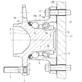
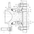
【解決手段】外方部材26とハブ輪2との間に装着されたシール8と、内輪3に装着され、ナックル27に固定された回転速度センサ33に所定の軸方向すきまを介して対峙されるパルサリング29とを備え、車体取付フランジ26aとナックル27とが突き合わせ状態で、外方部材26がナックル27にボルト12を介して接合されると共に、車体取付フランジ26aに環状凹部28が形成され、この環状凹部28にシール部材30が介装されて外方部材26のインナー側の開口部が液密的に閉塞されている。
【選択図】図5
Description
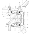
図1は、本発明に係る車輪用軸受装置の第1の実施形態を示す縦断面図である。なお、以下の説明では、車両に組み付けた状態で車両の外側寄りとなる側をアウター側(図1の左側)、中央寄り側をインナー側(図1の右側)という。
2・・・・・・・・・・・・・・・・・・・・・・ハブ輪
2a、3a・・・・・・・・・・・・・・・・・・内側転走面
2b・・・・・・・・・・・・・・・・・・・・・小径段部
2c・・・・・・・・・・・・・・・・・・・・・加締部
3・・・・・・・・・・・・・・・・・・・・・・内輪
4・・・・・・・・・・・・・・・・・・・・・・車輪取付フランジ
4a・・・・・・・・・・・・・・・・・・・・・円孔
4b・・・・・・・・・・・・・・・・・・・・・車輪取付フランジのインナー側の基部
5・・・・・・・・・・・・・・・・・・・・・・ハブボルト
6・・・・・・・・・・・・・・・・・・・・・・転動体
7・・・・・・・・・・・・・・・・・・・・・・保持器
8・・・・・・・・・・・・・・・・・・・・・・アウター側のシール
10、14、26・・・・・・・・・・・・・・・外方部材
10a・・・・・・・・・・・・・・・・・・・・外側転走面
10b、14a、26a・・・・・・・・・・・・車体取付フランジ
11、27・・・・・・・・・・・・・・・・・・ナックル
12・・・・・・・・・・・・・・・・・・・・・固定ボルト
13、17、17’、20、23、30、34・・シール部材
15、15’、28、28’、36・・・・・・・・環状凹部
16・・・・・・・・・・・・・・・・・・・・・シールド板
18、21、24、31・・・・・・・・・・・・芯金
18a、21a、24a・・・・・・・・・・・・円筒部
18b、21b、24b・・・・・・・・・・・・円板部
19、22、25、35・・・・・・・・・・・・シール部
25a・・・・・・・・・・・・・・・・・・・・基部
25b・・・・・・・・・・・・・・・・・・・・リップ部
27a・・・・・・・・・・・・・・・・・・・・センサ取付孔
29・・・・・・・・・・・・・・・・・・・・・パルサリング
31a・・・・・・・・・・・・・・・・・・・・嵌合部
31b・・・・・・・・・・・・・・・・・・・・立板部
32・・・・・・・・・・・・・・・・・・・・・磁気エンコーダ
33・・・・・・・・・・・・・・・・・・・・・回転速度センサ
51・・・・・・・・・・・・・・・・・・・・・内方部材
52・・・・・・・・・・・・・・・・・・・・・ハブ輪
52a、53a・・・・・・・・・・・・・・・・内側転走面
52b・・・・・・・・・・・・・・・・・・・・小径段部
52c・・・・・・・・・・・・・・・・・・・・加締部
53・・・・・・・・・・・・・・・・・・・・・内輪
54・・・・・・・・・・・・・・・・・・・・・車輪取付フランジ
55・・・・・・・・・・・・・・・・・・・・・ハブボルト
56・・・・・・・・・・・・・・・・・・・・・ボール
57・・・・・・・・・・・・・・・・・・・・・保持器
58、59・・・・・・・・・・・・・・・・・・シール
60・・・・・・・・・・・・・・・・・・・・・外方部材
60a・・・・・・・・・・・・・・・・・・・・外側転走面
60b・・・・・・・・・・・・・・・・・・・・車体取付フランジ
61・・・・・・・・・・・・・・・・・・・・・ナックル
61a・・・・・・・・・・・・・・・・・・・・底部
62・・・・・・・・・・・・・・・・・・・・・ドレーン孔
63・・・・・・・・・・・・・・・・・・・・・閉塞空間
A・・・・・・・・・・・・・・・・・・・・・・先端部
B・・・・・・・・・・・・・・・・・・・・・・湾曲部
S・・・・・・・・・・・・・・・・・・・・・・閉塞空間
δ・・・・・・・・・・・・・・・・・・・・・・シメシロ
θ・・・・・・・・・・・・・・・・・・・・・・傾斜角
Claims (10)
- 外周に懸架装置を構成するナックルに取り付けられるための車体取付フランジを一体に有し、内周に複列の外側転走面が一体に形成された外方部材と、
一端部に車輪を取り付けるための車輪取付フランジを一体に有し、外周にこの車輪取付フランジから軸方向に延びる小径段部が形成されたハブ輪、およびこのハブ輪の小径段部に圧入された少なくとも一つの内輪からなり、外周に前記複列の外側転走面に対向する複列の内側転走面が形成された内方部材と、
この内方部材と前記外方部材の両転走面間に保持器を介して転動自在に収容された複列の転動体と、
前記外方部材とハブ輪との間に形成される環状空間の開口部に装着されたシールとを備え、
前記車体取付フランジとナックルとが突き合わせ状態で、前記外方部材が当該ナックルにボルトを介して接合されると共に、
この接合部にシール部材が介装され、前記外方部材のインナー側の開口部が前記ナックルによって液密的に閉塞されていることを特徴とする車輪用軸受装置。 - 前記車体取付フランジとナックルの接合面に前記シール部材が介装され、このシール部材が、合成樹脂を主成分としたペースト状の液状ガスケットで構成されている請求項1に記載の車輪用軸受装置。
- 前記車体取付フランジに環状凹部が形成され、この環状凹部に前記シール部材が介装される共に、このシール部材が、当該環状凹部と前記ナックルに弾性接触されている請求項1に記載の車輪用軸受装置。
- 前記シール部材が、円筒部と、この円筒部から径方向に延びる円板部とからなり、断面略L字状で全体として円環状に形成された芯金と、この芯金の円板部に加硫接着によって一体に接合され、前記環状凹部とナックルに弾性接触されるシール部とで構成されている請求項3に記載の車輪用軸受装置。
- 前記芯金の円筒部が前記環状凹部に嵌合されている請求項4に記載の車輪用軸受装置。
- 前記環状凹部の開口部が奥側に比べて幅狭に形成され、前記シール部の外径部が所定のシメシロだけ弾性変形させて装着されている請求項4に記載の車輪用軸受装置。
- 前記車体取付フランジに環状凹部が径方向外方に向けて傾斜して形成されると共に、この環状凹部にOリングからなるシール部材が装着され、前記環状凹部とナックルに弾性接触されている請求項1に記載の車輪用軸受装置。
- 前記シール部材が、前記車体取付フランジの内周に圧入される芯金と、この芯金の外表面に加硫接着により回り込んで接合されたシール部とからなり、このシール部が、径方向外方に延び、断面が略くの字形に形成されたリップ部を有すると共に、このリップ部が前記環状凹部に介装され、当該リップ部の先端部と湾曲部が前記環状凹部とナックルに所定のシメシロで接触されている請求項3に記載の車輪用軸受装置。
- 前記外方部材のインナー側の端部と前記内輪との間に形成される環状空間の開口部にラビリンスシールを構成するシールド板が配設されている請求項1乃至8いずれかに記載の車輪用軸受装置。
- 前記内輪にパルサリングが装着され、このパルサリングが、前記内輪の外径に圧入固定される円筒状の嵌合部、およびこの嵌合部から径方向外方に延びる立板部を有する芯金と、前記立板部に加硫接着により一体に接合され、エラストマに磁性体粉が混入され、周方向に交互に磁極N、Sが着磁された磁気エンコーダとからなると共に、この磁気エンコーダが前記ナックルに固定された回転速度センサに所定の軸方向すきまを介して対峙している請求項1乃至8いずれかに記載の車輪用軸受装置。
Priority Applications (1)
| Application Number | Priority Date | Filing Date | Title |
|---|---|---|---|
| JP2008161442A JP5273845B2 (ja) | 2008-06-20 | 2008-06-20 | 車輪用軸受装置 |
Applications Claiming Priority (1)
| Application Number | Priority Date | Filing Date | Title |
|---|---|---|---|
| JP2008161442A JP5273845B2 (ja) | 2008-06-20 | 2008-06-20 | 車輪用軸受装置 |
Publications (2)
| Publication Number | Publication Date |
|---|---|
| JP2010000907A true JP2010000907A (ja) | 2010-01-07 |
| JP5273845B2 JP5273845B2 (ja) | 2013-08-28 |
Family
ID=41582985
Family Applications (1)
| Application Number | Title | Priority Date | Filing Date |
|---|---|---|---|
| JP2008161442A Active JP5273845B2 (ja) | 2008-06-20 | 2008-06-20 | 車輪用軸受装置 |
Country Status (1)
| Country | Link |
|---|---|
| JP (1) | JP5273845B2 (ja) |
Cited By (2)
| Publication number | Priority date | Publication date | Assignee | Title |
|---|---|---|---|---|
| WO2017179400A1 (ja) * | 2016-04-12 | 2017-10-19 | 日本精工株式会社 | ハブユニット軸受 |
| EP3205513A4 (en) * | 2014-10-10 | 2018-06-13 | NTN Corporation | Wheel bearing device |
Citations (4)
| Publication number | Priority date | Publication date | Assignee | Title |
|---|---|---|---|---|
| JPH07238942A (ja) * | 1994-02-28 | 1995-09-12 | Ntn Corp | 転がり軸受のシール装置 |
| JP2005022541A (ja) * | 2003-07-03 | 2005-01-27 | Koyo Seiko Co Ltd | 車輪用転がり軸受装置 |
| JP2005104260A (ja) * | 2003-09-30 | 2005-04-21 | Nsk Ltd | 車輪支持装置 |
| JP2005147298A (ja) * | 2003-11-18 | 2005-06-09 | Ntn Corp | 車輪用軸受装置 |
-
2008
- 2008-06-20 JP JP2008161442A patent/JP5273845B2/ja active Active
Patent Citations (4)
| Publication number | Priority date | Publication date | Assignee | Title |
|---|---|---|---|---|
| JPH07238942A (ja) * | 1994-02-28 | 1995-09-12 | Ntn Corp | 転がり軸受のシール装置 |
| JP2005022541A (ja) * | 2003-07-03 | 2005-01-27 | Koyo Seiko Co Ltd | 車輪用転がり軸受装置 |
| JP2005104260A (ja) * | 2003-09-30 | 2005-04-21 | Nsk Ltd | 車輪支持装置 |
| JP2005147298A (ja) * | 2003-11-18 | 2005-06-09 | Ntn Corp | 車輪用軸受装置 |
Cited By (4)
| Publication number | Priority date | Publication date | Assignee | Title |
|---|---|---|---|---|
| EP3205513A4 (en) * | 2014-10-10 | 2018-06-13 | NTN Corporation | Wheel bearing device |
| US10029513B2 (en) | 2014-10-10 | 2018-07-24 | Ntn Corporation | Wheel bearing apparatus |
| WO2017179400A1 (ja) * | 2016-04-12 | 2017-10-19 | 日本精工株式会社 | ハブユニット軸受 |
| US11273670B2 (en) | 2016-04-12 | 2022-03-15 | Nsk Ltd. | Hub unit bearing |
Also Published As
| Publication number | Publication date |
|---|---|
| JP5273845B2 (ja) | 2013-08-28 |
Similar Documents
| Publication | Publication Date | Title |
|---|---|---|
| JP6275465B2 (ja) | 密封装置およびこれを備えた車輪用軸受装置 | |
| JP5355987B2 (ja) | 回転速度検出装置付き車輪用軸受装置 | |
| JP2006266729A (ja) | 回転速度検出装置付き車輪用軸受装置 | |
| JP2007010480A (ja) | 回転速度検出装置付き車輪用軸受装置 | |
| JP4345988B2 (ja) | 車輪用軸受装置 | |
| JP4628049B2 (ja) | 回転速度検出装置付き車輪用軸受装置 | |
| JP2014013073A (ja) | 車輪用軸受装置 | |
| JP2008151727A (ja) | 回転速度検出装置及び回転速度検出装置付き車輪用軸受装置 | |
| JP4375790B2 (ja) | 回転速度検出装置付き車輪用軸受装置 | |
| JP2010019269A (ja) | 回転速度検出装置付き車輪用軸受装置およびその組立方法 | |
| JP5273845B2 (ja) | 車輪用軸受装置 | |
| JP4498052B2 (ja) | 回転速度検出装置付き車輪用軸受装置 | |
| JP2008151311A (ja) | 車輪用軸受装置 | |
| JP2010127296A (ja) | 車輪用軸受装置 | |
| JP4964611B2 (ja) | 回転速度検出装置付き車輪用軸受装置 | |
| JP2006349061A (ja) | 回転速度検出装置付き車輪用軸受装置 | |
| JP2006308396A (ja) | 回転速度検出装置付き車輪用軸受装置 | |
| JP2010230080A (ja) | 回転速度検出装置付き車輪用軸受装置 | |
| JP2009197941A (ja) | 回転速度検出装置付き車輪用軸受装置 | |
| JP6483460B2 (ja) | 密封装置およびこれを備えた車輪用軸受装置 | |
| JP4628053B2 (ja) | 回転速度検出装置付き車輪用軸受装置 | |
| JP2005299764A (ja) | 回転速度検出装置付き車輪用軸受装置 | |
| JP4582775B2 (ja) | 車輪用軸受装置 | |
| JP2009162677A (ja) | 回転速度検出装置付き車輪用軸受装置 | |
| JP2007211988A (ja) | 回転速度検出装置付き車輪用軸受装置 |
Legal Events
| Date | Code | Title | Description |
|---|---|---|---|
| A621 | Written request for application examination |
Free format text: JAPANESE INTERMEDIATE CODE: A621 Effective date: 20110602 |
|
| A977 | Report on retrieval |
Free format text: JAPANESE INTERMEDIATE CODE: A971007 Effective date: 20121115 |
|
| A131 | Notification of reasons for refusal |
Free format text: JAPANESE INTERMEDIATE CODE: A131 Effective date: 20121120 |
|
| A521 | Request for written amendment filed |
Free format text: JAPANESE INTERMEDIATE CODE: A523 Effective date: 20121210 |
|
| A02 | Decision of refusal |
Free format text: JAPANESE INTERMEDIATE CODE: A02 Effective date: 20130128 |
|
| A521 | Request for written amendment filed |
Free format text: JAPANESE INTERMEDIATE CODE: A523 Effective date: 20130402 |
|
| A911 | Transfer to examiner for re-examination before appeal (zenchi) |
Free format text: JAPANESE INTERMEDIATE CODE: A911 Effective date: 20130410 |
|
| TRDD | Decision of grant or rejection written | ||
| A01 | Written decision to grant a patent or to grant a registration (utility model) |
Free format text: JAPANESE INTERMEDIATE CODE: A01 Effective date: 20130513 |
|
| A61 | First payment of annual fees (during grant procedure) |
Free format text: JAPANESE INTERMEDIATE CODE: A61 Effective date: 20130513 |
|
| R150 | Certificate of patent or registration of utility model |
Free format text: JAPANESE INTERMEDIATE CODE: R150 Ref document number: 5273845 Country of ref document: JP Free format text: JAPANESE INTERMEDIATE CODE: R150 |
|
| R250 | Receipt of annual fees |
Free format text: JAPANESE INTERMEDIATE CODE: R250 |
|
| R250 | Receipt of annual fees |
Free format text: JAPANESE INTERMEDIATE CODE: R250 |
|
| R250 | Receipt of annual fees |
Free format text: JAPANESE INTERMEDIATE CODE: R250 |
|
| R250 | Receipt of annual fees |
Free format text: JAPANESE INTERMEDIATE CODE: R250 |
|
| R250 | Receipt of annual fees |
Free format text: JAPANESE INTERMEDIATE CODE: R250 |
|
| R250 | Receipt of annual fees |
Free format text: JAPANESE INTERMEDIATE CODE: R250 |
|
| R250 | Receipt of annual fees |
Free format text: JAPANESE INTERMEDIATE CODE: R250 |
|
| R250 | Receipt of annual fees |
Free format text: JAPANESE INTERMEDIATE CODE: R250 |