JP2005299764A - 回転速度検出装置付き車輪用軸受装置 - Google Patents
回転速度検出装置付き車輪用軸受装置 Download PDFInfo
- Publication number
- JP2005299764A JP2005299764A JP2004115145A JP2004115145A JP2005299764A JP 2005299764 A JP2005299764 A JP 2005299764A JP 2004115145 A JP2004115145 A JP 2004115145A JP 2004115145 A JP2004115145 A JP 2004115145A JP 2005299764 A JP2005299764 A JP 2005299764A
- Authority
- JP
- Japan
- Prior art keywords
- encoder
- seal
- wheel
- rotational speed
- cylindrical portion
- Prior art date
- Legal status (The legal status is an assumption and is not a legal conclusion. Google has not performed a legal analysis and makes no representation as to the accuracy of the status listed.)
- Pending
Links
- 238000001514 detection method Methods 0.000 title claims abstract description 51
- 238000005096 rolling process Methods 0.000 claims description 55
- 239000000725 suspension Substances 0.000 claims description 7
- 230000002093 peripheral effect Effects 0.000 claims description 3
- 239000006247 magnetic powder Substances 0.000 description 10
- 238000007789 sealing Methods 0.000 description 6
- 229920001971 elastomer Polymers 0.000 description 4
- 239000004519 grease Substances 0.000 description 4
- 239000000428 dust Substances 0.000 description 3
- 230000004048 modification Effects 0.000 description 3
- 238000012986 modification Methods 0.000 description 3
- OKTJSMMVPCPJKN-UHFFFAOYSA-N Carbon Chemical compound [C] OKTJSMMVPCPJKN-UHFFFAOYSA-N 0.000 description 2
- 229910000954 Medium-carbon steel Inorganic materials 0.000 description 2
- 229910052799 carbon Inorganic materials 0.000 description 2
- 230000004907 flux Effects 0.000 description 2
- 230000006698 induction Effects 0.000 description 2
- 230000001050 lubricating effect Effects 0.000 description 2
- 230000036316 preload Effects 0.000 description 2
- 238000007493 shaping process Methods 0.000 description 2
- 229920003002 synthetic resin Polymers 0.000 description 2
- 239000000057 synthetic resin Substances 0.000 description 2
- -1 S53C Chemical compound 0.000 description 1
- 229910000831 Steel Inorganic materials 0.000 description 1
- 229910000963 austenitic stainless steel Inorganic materials 0.000 description 1
- 238000005452 bending Methods 0.000 description 1
- 239000010960 cold rolled steel Substances 0.000 description 1
- 230000007797 corrosion Effects 0.000 description 1
- 238000005260 corrosion Methods 0.000 description 1
- 238000002788 crimping Methods 0.000 description 1
- 239000000806 elastomer Substances 0.000 description 1
- 238000005242 forging Methods 0.000 description 1
- 239000000463 material Substances 0.000 description 1
- 239000004033 plastic Substances 0.000 description 1
- 239000000843 powder Substances 0.000 description 1
- 102220097517 rs876659265 Human genes 0.000 description 1
- 239000010935 stainless steel Substances 0.000 description 1
- 229910001220 stainless steel Inorganic materials 0.000 description 1
- 239000010959 steel Substances 0.000 description 1
- 239000000126 substance Substances 0.000 description 1
- 229910000859 α-Fe Inorganic materials 0.000 description 1
Images
Landscapes
- Rolling Contact Bearings (AREA)
Abstract
コンパクト化と共に、検出部に異物が侵入するのを防止し、耐久性と信頼性を向上させた回転速度検出装置付き車輪用軸受装置を提供する。
【解決手段】
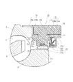
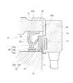
内輪6に外嵌されたエンコーダ19と、これに対向して外方部材4の端部に装着された円環状のセンサホルダ15と、これに一体モールドされ、エンコーダ19に所定の径方向すきまを介して対峙する回転速度センサー20とを備えた回転速度検出装置付き車輪用軸受装置において、エンコーダ19が円環状をなす磁気エンコーダからなると共に、このエンコーダ19のインボード側にシール11が配設され、このシール11が、センサホルダ15と内輪6にそれぞれ装着され、互いに対向して配置された環状の第1および第2のシール板21、22からなり、この第2のシール板22にエンコーダ19が一体に加硫接着されている。
【選択図】図2
Description
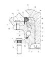
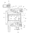
図1は、本発明に係る回転速度検出装置付き車輪用軸受装置の第1の実施形態を示す縦断面図、図2は、図1の要部拡大図である。なお、以下の説明では、車両に組み付けた状態で車両の外側寄りとなる側をアウトボード側(図面左側)、中央寄り側をインボード側(図面右側)という。
複列の転がり軸受2は、外方部材4と内方部材3と複列の転動体(ボール)5、5とを有し、外方部材4は、S53C等の炭素0.40〜0.80wt%を含む中炭素鋼からなり、外周にナックルNに取り付けるための車体取付フランジ4bを一体に有している。内周には複列の外側転走面4a、4aが形成され、高周波焼入れによって表面硬さを54〜64HRCの範囲に硬化層が形成されている。
1a、6a・・・・・・・・・・・・内側転走面
1b・・・・・・・・・・・・・・・小径段部
1c・・・・・・・・・・・・・・・セレーション
2・・・・・・・・・・・・・・・・複列の転がり軸受
3・・・・・・・・・・・・・・・・内方部材
4・・・・・・・・・・・・・・・・外方部材
4a・・・・・・・・・・・・・・・外側転走面
4b・・・・・・・・・・・・・・・車体取付フランジ
5・・・・・・・・・・・・・・・・転動体
6・・・・・・・・・・・・・・・・内輪
7・・・・・・・・・・・・・・・・車輪取付フランジ
7a・・・・・・・・・・・・・・・ハブボルト
8・・・・・・・・・・・・・・・・加締部
9・・・・・・・・・・・・・・・・保持器
10・・・・・・・・・・・・・・・アウトボード側のシール
11、11’・・・・・・・・・・・・インボード側のシール
12・・・・・・・・・・・・・・・外側継手部材
13・・・・・・・・・・・・・・・肩部
14・・・・・・・・・・・・・・・固定ナット
15・・・・・・・・・・・・・・・センサホルダ
16・・・・・・・・・・・・・・・嵌合環
16a・・・・・・・・・・・・・・嵌合部
16b・・・・・・・・・・・・・・鍔部
16c、21a・・・・・・・・・・円筒部
17・・・・・・・・・・・・・・・保持部
18・・・・・・・・・・・・・・・穿孔
19・・・・・・・・・・・・・・・磁気エンコーダ
20・・・・・・・・・・・・・・・回転速度センサー
21・・・・・・・・・・・・・・・第1のシール板
21b、22c、25b、29b・・立板部
22・・・・・・・・・・・・・・・第2のシール板
22b・・・・・・・・・・・・・・大径段部
22d・・・・・・・・・・・・・・舌片
23、26、27、28、30・・・ラビリンスシール
24・・・・・・・・・・・・・・・シール部材
24a・・・・・・・・・・・・・・サイドリップ
24b・・・・・・・・・・・・・・グリースリップ
24c・・・・・・・・・・・・・・中間リップ
25、29・・・・・・・・・・・・シールド
25a、29a・・・・・・・・・・第1円筒部
25c、29c・・・・・・・・・・第2円筒部
51・・・・・・・・・・・・・・・外方部材
51a・・・・・・・・・・・・・・外側転走面
51b・・・・・・・・・・・・・・車体取付フランジ
52・・・・・・・・・・・・・・・内方部材
53・・・・・・・・・・・・・・・転動体
54・・・・・・・・・・・・・・・車輪取付フランジ
54a・・・・・・・・・・・・・・ハブボルト
55・・・・・・・・・・・・・・・ハブ輪
55a、56a・・・・・・・・・・内側転走面
55b・・・・・・・・・・・・・・小径段部
55c・・・・・・・・・・・・・・セレーション
56・・・・・・・・・・・・・・・内輪
57・・・・・・・・・・・・・・・保持器
58、59・・・・・・・・・・・・シール
60・・・・・・・・・・・・・・・外側継手部材
61・・・・・・・・・・・・・・・ステム部
62・・・・・・・・・・・・・・・第1のシール板
63・・・・・・・・・・・・・・・第2のシール板
63a・・・・・・・・・・・・・・円筒部
63b・・・・・・・・・・・・・・立板部
64・・・・・・・・・・・・・・・磁気エンコーダ
65・・・・・・・・・・・・・・・芯金
66・・・・・・・・・・・・・・・シール部材
66a・・・・・・・・・・・・・・サイドリップ
66b、66c・・・・・・・・・・ラジアルリップ
67・・・・・・・・・・・・・・・嵌合筒
67a・・・・・・・・・・・・・・嵌合筒部
67b・・・・・・・・・・・・・・内向鍔部
68・・・・・・・・・・・・・・・保持部
69・・・・・・・・・・・・・・・センサホルダ
70・・・・・・・・・・・・・・・回転速度センサー
71・・・・・・・・・・・・・・・微小隙間
N・・・・・・・・・・・・・・・・ナックル
Claims (6)
- 外周に懸架装置に取り付けるための車体取付フランジを一体に有し、内周に複列の外側転走面が形成された外方部材と、
一端部に車輪を取り付けるための車輪取付フランジを一体に有し、外周に軸方向に延びる円筒状の小径段部が形成されたハブ輪、およびこのハブ輪の小径段部に圧入された内輪とからなり、外周に前記複列の外側転走面に対向する内側転走面が形成された内方部材と、
前記外方部材および内方部材のそれぞれの転走面間に転動自在に収容された複列の転動体と、
前記内輪に外嵌されたエンコーダと、このエンコーダに対向するように前記外方部材の端部に装着された円環状のセンサホルダと、
このセンサホルダに一体モールドされ、前記エンコーダに所定の径方向すきまを介して対峙する回転速度センサーと、を備えた回転速度検出装置付き車輪用軸受装置において、
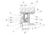
前記エンコーダが円環状をなし、その円周方向に関する特性が交互にかつ等間隔に変化するように構成されると共に、このエンコーダのインボード側にシールが配設され、このシールが、前記センサホルダと内輪にそれぞれ装着され、互いに対向して配置された環状の第1および第2のシール板からなり、前記エンコーダがこの第2のシール板に一体に設けられていることを特徴とする回転速度検出装置付き車輪用軸受装置。 - 前記センサホルダが、鋼板製の嵌合環と、この嵌合環に一体モールドされた保持部とからなると共に、前記嵌合環が、外方部材の外周に圧入される円筒状の嵌合部と、この嵌合部から径方向内方に延び、前記外方部材の端面に密着される鍔部と、この鍔部から軸方向に延びる円筒部とからなり、この円筒部に前記第1のシール板が内嵌されている請求項1に記載の回転速度検出装置付き車輪用軸受装置。
- 前記第2のシール板が、前記内輪に外嵌され、その外周面に前記エンコーダが一体に設けられた円筒部と、この円筒部から軸方向に延びる円筒状の大径段部と、この大径段部から径方向外方に延びる立板部とを有する断面略L字状に形成され、この立板部の先端部にラビリンスシールが構成されている請求項1または2に記載の回転速度検出装置付き車輪用軸受装置。
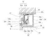
- 前記シールのさらにインボード側に断面略コの字状のシールドが配設され、このシールドを外側継手部材の肩部に僅かな径方向すきまを介して対向させてラビリンスシールが構成される請求項1乃至3いずれかに記載の回転速度検出装置付き車輪用軸受装置。
- 前記シールドは、前記センサホルダに内嵌される第1円筒部と、この第1円筒部から径方向内方に延びる立板部と、この立板部から軸方向に延びる第2円筒部とからなり、前記立板部を前記第2のシール板に僅かな軸方向すきまを介して対向させてラビリンスシールが構成されている請求項4に記載の回転速度検出装置付き車輪用軸受装置。
- 前記シールドは、前記センサホルダに内嵌される第1円筒部と、この第1円筒部から径方向内方に延びる立板部と、この立板部から軸方向に延びる第2円筒部とからなり、前記第2円筒部を前記内輪の端面に僅かな軸方向すきまを介して対向させてラビリンスシールが構成されている請求項4に記載の回転速度検出装置付き車輪用軸受装置。
Priority Applications (2)
| Application Number | Priority Date | Filing Date | Title |
|---|---|---|---|
| JP2004115145A JP2005299764A (ja) | 2004-04-09 | 2004-04-09 | 回転速度検出装置付き車輪用軸受装置 |
| US11/101,351 US7618194B2 (en) | 2004-04-09 | 2005-04-07 | Wheel bearing apparatus incorporated with a wheel speed detecting apparatus |
Applications Claiming Priority (1)
| Application Number | Priority Date | Filing Date | Title |
|---|---|---|---|
| JP2004115145A JP2005299764A (ja) | 2004-04-09 | 2004-04-09 | 回転速度検出装置付き車輪用軸受装置 |
Publications (2)
| Publication Number | Publication Date |
|---|---|
| JP2005299764A true JP2005299764A (ja) | 2005-10-27 |
| JP2005299764A5 JP2005299764A5 (ja) | 2006-11-16 |
Family
ID=35331543
Family Applications (1)
| Application Number | Title | Priority Date | Filing Date |
|---|---|---|---|
| JP2004115145A Pending JP2005299764A (ja) | 2004-04-09 | 2004-04-09 | 回転速度検出装置付き車輪用軸受装置 |
Country Status (1)
| Country | Link |
|---|---|
| JP (1) | JP2005299764A (ja) |
Cited By (5)
| Publication number | Priority date | Publication date | Assignee | Title |
|---|---|---|---|---|
| WO2008084613A1 (ja) * | 2007-01-09 | 2008-07-17 | Ntn Corporation | センサ付シール装置および車輪用軸受装置 |
| JP2008304011A (ja) * | 2007-06-08 | 2008-12-18 | Jtekt Corp | ハブユニット |
| WO2008152987A1 (ja) * | 2007-06-08 | 2008-12-18 | Jtekt Corporation | ハブユニット |
| WO2009005085A1 (ja) * | 2007-07-03 | 2009-01-08 | Jtekt Corporation | センサ装置およびセンサ付き転がり軸受装置 |
| JP2009008599A (ja) * | 2007-06-29 | 2009-01-15 | Jtekt Corp | 回転速度検出装置 |
-
2004
- 2004-04-09 JP JP2004115145A patent/JP2005299764A/ja active Pending
Cited By (5)
| Publication number | Priority date | Publication date | Assignee | Title |
|---|---|---|---|---|
| WO2008084613A1 (ja) * | 2007-01-09 | 2008-07-17 | Ntn Corporation | センサ付シール装置および車輪用軸受装置 |
| JP2008304011A (ja) * | 2007-06-08 | 2008-12-18 | Jtekt Corp | ハブユニット |
| WO2008152987A1 (ja) * | 2007-06-08 | 2008-12-18 | Jtekt Corporation | ハブユニット |
| JP2009008599A (ja) * | 2007-06-29 | 2009-01-15 | Jtekt Corp | 回転速度検出装置 |
| WO2009005085A1 (ja) * | 2007-07-03 | 2009-01-08 | Jtekt Corporation | センサ装置およびセンサ付き転がり軸受装置 |
Similar Documents
| Publication | Publication Date | Title |
|---|---|---|
| JP4679192B2 (ja) | 回転速度検出装置付き車輪用軸受装置 | |
| JP4628049B2 (ja) | 回転速度検出装置付き車輪用軸受装置 | |
| JP4784967B2 (ja) | 回転速度検出装置付き車輪用軸受装置 | |
| JP4375790B2 (ja) | 回転速度検出装置付き車輪用軸受装置 | |
| JP2006112919A (ja) | 回転速度検出装置付き車輪用軸受装置 | |
| JP4748775B2 (ja) | 回転速度検出装置付き車輪用軸受装置 | |
| JP4498052B2 (ja) | 回転速度検出装置付き車輪用軸受装置 | |
| JP2007010480A (ja) | 回転速度検出装置付き車輪用軸受装置 | |
| JP2006284402A (ja) | 回転速度検出装置付き車輪用軸受装置 | |
| JP4628395B2 (ja) | 回転速度検出装置付き車輪用軸受装置 | |
| JP2005299764A (ja) | 回転速度検出装置付き車輪用軸受装置 | |
| JP4726042B2 (ja) | 回転速度検出装置付き車輪用軸受装置 | |
| JP4964611B2 (ja) | 回転速度検出装置付き車輪用軸受装置 | |
| JP4628053B2 (ja) | 回転速度検出装置付き車輪用軸受装置 | |
| JP2008151727A (ja) | 回転速度検出装置及び回転速度検出装置付き車輪用軸受装置 | |
| JP2008180544A (ja) | 回転速度検出装置付き車輪用軸受装置 | |
| JP2007232731A (ja) | 回転速度検出装置付き車輪用軸受装置 | |
| JP4803572B2 (ja) | 磁気エンコーダおよびこれを具備した車輪用軸受装置 | |
| JP2008024051A (ja) | 駆動車輪用軸受装置 | |
| JP2006308396A (ja) | 回転速度検出装置付き車輪用軸受装置 | |
| JP2009138781A (ja) | 回転速度検出装置付き車輪用軸受装置 | |
| JP2006349061A (ja) | 回転速度検出装置付き車輪用軸受装置 | |
| JP2009030756A (ja) | 回転速度検出装置付き車輪用軸受装置 | |
| JP2008261463A (ja) | 回転速度検出装置付き車輪用軸受装置 | |
| JP2008151623A (ja) | センサホルダおよびこれを内蔵した回転速度検出装置付き車輪用軸受装置 |
Legal Events
| Date | Code | Title | Description |
|---|---|---|---|
| A521 | Written amendment |
Free format text: JAPANESE INTERMEDIATE CODE: A523 Effective date: 20060928 |
|
| A621 | Written request for application examination |
Effective date: 20060928 Free format text: JAPANESE INTERMEDIATE CODE: A621 |
|
| A871 | Explanation of circumstances concerning accelerated examination |
Effective date: 20060928 Free format text: JAPANESE INTERMEDIATE CODE: A871 |
|
| A975 | Report on accelerated examination |
Effective date: 20061013 Free format text: JAPANESE INTERMEDIATE CODE: A971005 |
|
| A131 | Notification of reasons for refusal |
Free format text: JAPANESE INTERMEDIATE CODE: A131 Effective date: 20061114 |
|
| A521 | Written amendment |
Free format text: JAPANESE INTERMEDIATE CODE: A523 Effective date: 20061226 |
|
| A131 | Notification of reasons for refusal |
Free format text: JAPANESE INTERMEDIATE CODE: A131 Effective date: 20070206 |
|
| A521 | Written amendment |
Free format text: JAPANESE INTERMEDIATE CODE: A523 Effective date: 20070409 |
|
| A02 | Decision of refusal |
Free format text: JAPANESE INTERMEDIATE CODE: A02 Effective date: 20070515 |
|
| A521 | Written amendment |
Effective date: 20070717 Free format text: JAPANESE INTERMEDIATE CODE: A523 |
|
| A911 | Transfer of reconsideration by examiner before appeal (zenchi) |
Effective date: 20070723 Free format text: JAPANESE INTERMEDIATE CODE: A911 |
|
| A912 | Removal of reconsideration by examiner before appeal (zenchi) |
Effective date: 20070907 Free format text: JAPANESE INTERMEDIATE CODE: A912 |