JP2005299764A - Bearing device for wheel with rotation speed detection device - Google Patents
Bearing device for wheel with rotation speed detection device Download PDFInfo
- Publication number
- JP2005299764A JP2005299764A JP2004115145A JP2004115145A JP2005299764A JP 2005299764 A JP2005299764 A JP 2005299764A JP 2004115145 A JP2004115145 A JP 2004115145A JP 2004115145 A JP2004115145 A JP 2004115145A JP 2005299764 A JP2005299764 A JP 2005299764A
- Authority
- JP
- Japan
- Prior art keywords
- encoder
- seal
- wheel
- rotational speed
- cylindrical portion
- Prior art date
- Legal status (The legal status is an assumption and is not a legal conclusion. Google has not performed a legal analysis and makes no representation as to the accuracy of the status listed.)
- Pending
Links
- 238000001514 detection method Methods 0.000 title claims abstract description 51
- 238000005096 rolling process Methods 0.000 claims description 55
- 239000000725 suspension Substances 0.000 claims description 7
- 230000002093 peripheral effect Effects 0.000 claims description 3
- 239000006247 magnetic powder Substances 0.000 description 10
- 238000007789 sealing Methods 0.000 description 6
- 229920001971 elastomer Polymers 0.000 description 4
- 239000004519 grease Substances 0.000 description 4
- 239000000428 dust Substances 0.000 description 3
- 230000004048 modification Effects 0.000 description 3
- 238000012986 modification Methods 0.000 description 3
- OKTJSMMVPCPJKN-UHFFFAOYSA-N Carbon Chemical compound [C] OKTJSMMVPCPJKN-UHFFFAOYSA-N 0.000 description 2
- 229910000954 Medium-carbon steel Inorganic materials 0.000 description 2
- 229910052799 carbon Inorganic materials 0.000 description 2
- 230000004907 flux Effects 0.000 description 2
- 230000006698 induction Effects 0.000 description 2
- 230000001050 lubricating effect Effects 0.000 description 2
- 230000036316 preload Effects 0.000 description 2
- 238000007493 shaping process Methods 0.000 description 2
- 229920003002 synthetic resin Polymers 0.000 description 2
- 239000000057 synthetic resin Substances 0.000 description 2
- -1 S53C Chemical compound 0.000 description 1
- 229910000831 Steel Inorganic materials 0.000 description 1
- 229910000963 austenitic stainless steel Inorganic materials 0.000 description 1
- 238000005452 bending Methods 0.000 description 1
- 239000010960 cold rolled steel Substances 0.000 description 1
- 230000007797 corrosion Effects 0.000 description 1
- 238000005260 corrosion Methods 0.000 description 1
- 238000002788 crimping Methods 0.000 description 1
- 239000000806 elastomer Substances 0.000 description 1
- 238000005242 forging Methods 0.000 description 1
- 239000000463 material Substances 0.000 description 1
- 239000004033 plastic Substances 0.000 description 1
- 239000000843 powder Substances 0.000 description 1
- 102220097517 rs876659265 Human genes 0.000 description 1
- 239000010935 stainless steel Substances 0.000 description 1
- 229910001220 stainless steel Inorganic materials 0.000 description 1
- 239000010959 steel Substances 0.000 description 1
- 239000000126 substance Substances 0.000 description 1
- 229910000859 α-Fe Inorganic materials 0.000 description 1
Images
Landscapes
- Rolling Contact Bearings (AREA)
Abstract
Description
本発明は、自動車等の車輪を回転自在に支承すると共に、この車輪の回転速度を検出する回転速度検出装置が内蔵された回転速度検出装置付き車輪用軸受装置に関するものである。 The present invention relates to a wheel bearing device with a rotational speed detection device that rotatably supports a wheel of an automobile or the like and incorporates a rotational speed detection device that detects the rotational speed of the wheel.
自動車の車輪を懸架装置に対して回転自在に支承すると共に、アンチロックブレーキシステム(ABS)を制御すべく車輪の回転速度を検出するために、回転速度検出装置が内蔵された回転速度検出装置付き車輪用軸受装置が一般的に知られている。従来、このような車輪用軸受装置は、転動体を介して転接する内方部材および外方部材の間にシール装置が設けられ、円周方向に磁極を交互に並べてなる磁気エンコーダを前記シール装置に一体化させると共に、磁気エンコーダと、この磁気エンコーダに対面配置され、車輪の回転に伴う磁気エンコーダの磁極変化を検出する回転速度センサーとで回転速度検出装置が構成されている。 Rotation speed detection device with built-in rotation speed detection device to detect the rotation speed of the wheel to control the anti-lock brake system (ABS) while supporting the wheel of the automobile rotatably with the suspension system Wheel bearing devices are generally known. Conventionally, in such a wheel bearing device, a sealing device is provided between an inner member and an outer member that are in rolling contact with a rolling element, and a magnetic encoder in which magnetic poles are alternately arranged in a circumferential direction is provided as the sealing device. In addition, the rotational speed detection device is configured by a magnetic encoder and a rotational speed sensor that is arranged to face the magnetic encoder and detects a change in magnetic pole of the magnetic encoder as the wheel rotates.
前記回転速度センサーは、懸架装置を構成するナックルに車輪用軸受装置が装着された後、当該ナックルに装着されているものが一般的である。しかし、この回転速度センサーと磁気エンコーダとのエアギャップ調整作業の煩雑さを解消すると共に、よりコンパクト化を狙って最近では、回転速度センサーをも軸受に内蔵した回転速度検出装置付き車輪用軸受装置が提案されている。 Generally, the rotational speed sensor is attached to the knuckle after the wheel bearing device is attached to the knuckle constituting the suspension device. However, in order to eliminate the complexity of the air gap adjustment work between the rotation speed sensor and the magnetic encoder and to achieve a more compact design, recently, a bearing device for a wheel with a rotation speed detection device in which the rotation speed sensor is also incorporated in the bearing. Has been proposed.
このような回転速度検出装置付き車輪用軸受装置の一例として図5に示すような構造が知られている。この回転速度検出装置付き車輪用軸受装置は、図示しない懸架装置に支持固定され、固定部材となる外方部材51と、この外方部材51に複列の転動体(ボール)53、53を介して内挿された内方部材52とを有し、外方部材51は車体取付フランジ51bを外周に一体に有し、内周には複列の外側転走面51a、51aが形成されている。一方、内方部材52は、前記した外方部材51の外側転走面51a、51aに対向する複列の内側転走面55a、56aが形成されている。これら複列の内側転走面55a、56aのうち一方の内側転走面55aはハブ輪55の外周に一体形成され、他方の内側転走面56aは、ハブ輪55の内側転走面55aから軸方向に延びる円筒状の小径段部55bに圧入された内輪56の外周に形成されている。そして、複列の転動体53、53がこれら両転走面間にそれぞれ収容され、保持器57、57によって転動自在に保持されている。
A structure as shown in FIG. 5 is known as an example of such a wheel bearing device with a rotational speed detection device. This wheel bearing device with a rotational speed detection device is supported and fixed to a suspension device (not shown), an
ハブ輪55は、外周に車輪(図示せず)を取り付けるための車輪取付フランジ54を一体に有し、この車輪取付フランジ54の円周等配位置には車輪を固定するためのハブボルト54aが植設されている。また、ハブ輪55の内周には、図示しない等速自在継手を構成する外側継手部材60のステム部61が内嵌されるセレーション55cが形成されている。内方部材52は、このハブ輪55と内輪56を指す。そして、外方部材51の端部にはシール58、59が装着され、軸受内部に封入された潤滑グリースの漏洩と、外部から軸受内部に雨水やダスト等が侵入するのを防止している。
The
インボード側のシール59は、図6に拡大して示すように、外方部材51の端部内周に内嵌され、断面L字状に形成された第1のシール板62と、この第1のシール板62に対向し、断面L字状に形成された第2のシール板63とからなる。この第2のシール板63は、内輪56に外嵌される円筒部63aと、この円筒部63aから径方向外方に延びる立板部63bとを有し、この立板部63bの外側面には、磁性体粉の混入され、周方向に交互に磁極N、Sが形成されたゴム磁石からなる磁気エンコーダ64が一体に加硫接着されている。
As shown in an enlarged view in FIG. 6, the
一方、第1のシール板62は、断面L字状に形成された芯金65と、この芯金65に一体に加硫接着され、前記第2のシール板63における立板部63bの内側面に摺接するサイドリップ66aと、円筒部63aに摺接する一対のラジアルリップ66b、66cとからなるシール部材66とを有している。
On the other hand, the
外方部材51の端部には、嵌合筒67と、この嵌合筒67に結合された保持部68とからなる円環状のセンサホルダ69が装着されている。嵌合筒67は、嵌合筒部67aと、この嵌合筒部67aから径方向内方に延びる内向鍔部67bとからなり、断面L字状で全体が円環状に形成されている。
An
保持部68は、その内部に前記磁気エンコーダ64に所定のエアギャップを介して対峙する回転速度センサー70が包埋され、合成樹脂で円弧状に一体モールド成形されている。回転速度センサー70は、ホール素子、磁気抵抗素子(MR素子)等、磁束の流れ方向に応じて特性を変化させる磁気検出素子と、この磁気検出素子の出力波形を整える波形成形回路が組み込まれたICとからなる。
The
ここで、内輪56の端面と嵌合筒67の内向鍔部67bとを微小隙間71を介して全周に亙り近接対向させてラビリンスシールが構成されている。これにより、自動車の完成品メーカの組立ラインへの搬送時を含む、ハブ輪55の内径に外側継手部材60のステム部61を嵌合する以前の状態でも、磁気エンコーダ64と回転速度センサー70の検出部との間に、外部から磁性粉末等の異物が侵入するのを防止できる。したがって、車輪の回転速度検出の信頼性向上を図ることができる。
しかしながら、こうした従来の回転速度検出装置付き車輪用軸受装置は、自動車の完成品メーカの組立ラインへの搬送時を含む、ハブ輪55の内径に外側継手部材60のステム部61を嵌合する以前の状態でも、磁気エンコーダ64と回転速度センサー70の検出部との間に、外部から磁性粉末等の異物が侵入するのを防止できる特徴を具備するも、こうしたラビリンスシールあるいは簡易的な接触シール等では、過酷な環境となる実走時において、磁気エンコーダ64と回転速度センサー70の検出部との間に外部からダストや磁性粉末等の異物が侵入するのは必至である。こうした異物は磁気エンコーダ64を摩耗させると共に、回転速度センサー70の検出部を損傷させ、車輪の回転速度検出の信頼性が低下する恐れがあった。
However, such a conventional wheel bearing device with a rotational speed detection device is used before the
本発明は、このような事情に鑑みてなされたもので、コンパクト化と共に、検出部に異物が侵入するのを防止し、耐久性と信頼性を向上させた回転速度検出装置付き車輪用軸受装置を提供することを目的としている。 SUMMARY OF THE INVENTION The present invention has been made in view of such circumstances, and has a wheel bearing device with a rotational speed detection device that is compact and prevents foreign matter from entering the detection portion and has improved durability and reliability. The purpose is to provide.
係る目的を達成すべく、本発明のうち請求項1記載の発明は、外周に懸架装置に取り付けるための車体取付フランジを一体に有し、内周に複列の外側転走面が形成された外方部材と、一端部に車輪を取り付けるための車輪取付フランジを一体に有し、外周に軸方向に延びる円筒状の小径段部が形成されたハブ輪、およびこのハブ輪の小径段部に圧入された内輪とからなり、外周に前記複列の外側転走面に対向する内側転走面が形成された内方部材と、前記外方部材および内方部材のそれぞれの転走面間に転動自在に収容された複列の転動体と、前記内輪に外嵌されたエンコーダと、このエンコーダに対向するように前記外方部材の端部に装着された円環状のセンサホルダと、このセンサホルダに一体モールドされ、前記エンコーダに所定の径方向すきまを介して対峙する回転速度センサーと、を備えた回転速度検出装置付き車輪用軸受装置において、前記エンコーダが円環状をなし、その円周方向に関する特性が交互にかつ等間隔に変化するように構成されると共に、このエンコーダのインボード側にシールが配設され、このシールが、前記センサホルダと内輪にそれぞれ装着され、互いに対向して配置された環状の第1および第2のシール板からなり、前記エンコーダがこの第2のシール板に一体に設けられている構成を採用した。
In order to achieve the object, the invention according to
このように、内輪回転タイプの回転速度検出装置付き車輪用軸受装置において、エンコーダが円環状をなし、その円周方向に関する特性が交互にかつ等間隔に変化するように構成されると共に、このエンコーダのインボード側にシールが配設され、このシールが、センサホルダと内輪にそれぞれ装着され、互いに対向して配置された環状の第1および第2のシール板からなり、エンコーダがこの第2のシール板に一体に設けられているので、自動車の完成品メーカの組立ラインへの搬送時を含む、ハブ輪に外側継手部材を内嵌する以前の状態でも、また、過酷な環境となる実走時においても、エンコーダと回転速度センサーの検出部との間に、外部から磁性粉末等の異物が侵入するのを確実に防止することができる。したがって、車輪の回転速度検出の信頼性を格段に向上させることができる。 As described above, in the wheel bearing device with a rotational speed detection device of the inner ring rotation type, the encoder is formed in an annular shape, and the characteristics in the circumferential direction are alternately and equally spaced. A seal is disposed on the inboard side, and the seal includes annular first and second seal plates that are respectively attached to the sensor holder and the inner ring and disposed opposite to each other. Since it is provided integrally with the seal plate, even in the state before the outer joint member is fitted into the hub wheel, including during transportation to the assembly line of the finished product manufacturer of the automobile, it is also a severe driving environment that becomes a harsh environment Even in this case, it is possible to reliably prevent foreign matter such as magnetic powder from entering between the encoder and the detection unit of the rotation speed sensor. Therefore, the reliability of detecting the rotational speed of the wheel can be significantly improved.
好ましくは、請求項2に記載の発明のように、前記センサホルダが、鋼板製の嵌合環と、この嵌合環に一体モールドされた保持部とからなると共に、前記嵌合環が、外方部材の外周に圧入される円筒状の嵌合部と、この嵌合部から径方向内方に延び、前記外方部材の端面に密着される鍔部と、この鍔部から軸方向に延びる円筒部とからなり、この円筒部に前記第1のシール板が内嵌されていれば、径方向のコンパクト化ができると共に、回転速度センサー等の取り巻きを簡素化でき、組立作業性が一段と向上する。
Preferably, as in the invention described in
また、請求項3に記載の発明は、前記第2のシール板が、前記内輪に外嵌され、その外周面に前記エンコーダが一体に設けられた円筒部と、この円筒部から軸方向に延びる円筒状の大径段部と、この大径段部から径方向外方に延びる立板部とを有する断面略L字状に形成され、この立板部の先端部にラビリンスシールが構成されているので、一層密封性が向上し、回転速度検出の信頼性を向上させることができる。 According to a third aspect of the present invention, the second seal plate is externally fitted to the inner ring, and a cylindrical portion in which the encoder is integrally provided on an outer peripheral surface thereof, and extends from the cylindrical portion in the axial direction. It is formed in a substantially L-shaped cross section having a cylindrical large-diameter step portion and a standing plate portion extending radially outward from the large-diameter step portion, and a labyrinth seal is configured at the tip of the standing plate portion. As a result, the sealing performance is further improved and the reliability of detecting the rotational speed can be improved.
また、請求項4に記載の発明は、前記シールのさらにインボード側に断面略コの字状のシールドが配設され、このシールドを外側継手部材の肩部に僅かな径方向すきまを介して対向させてラビリンスシールが構成されるので、実走時において一層密封性が向上する。 According to a fourth aspect of the present invention, a shield having a substantially U-shaped cross section is disposed further on the inboard side of the seal, and the shield is placed on the shoulder of the outer joint member through a slight radial clearance. Since the labyrinth seal is configured to face each other, the sealing performance is further improved during actual running.
また、前記シールドは、請求項5に記載の発明のように、前記センサホルダに内嵌される第1円筒部と、この第1円筒部から径方向内方に延びる立板部と、この立板部から軸方向に延びる第2円筒部とからなり、前記立板部を前記第2のシール板に僅かな軸方向すきまを介して対向させてラビリンスシールが構成されていても良いし、また、請求項6に記載の発明のように、前記センサホルダに内嵌される第1円筒部と、この第1円筒部から径方向内方に延びる立板部と、この立板部から軸方向に延びる第2円筒部とからなり、前記第2円筒部を前記内輪の端面に僅かな軸方向すきまを介して対向させてラビリンスシールが構成されていても良い。
The shield includes a first cylindrical portion fitted into the sensor holder, a standing plate portion extending radially inward from the first cylindrical portion, and The labyrinth seal may be configured by a second cylindrical portion extending in the axial direction from the plate portion, with the upright plate portion facing the second seal plate via a slight axial clearance, and As in the invention described in
本発明に係る回転速度検出装置付き車輪用軸受装置は、外周に懸架装置に取り付けるための車体取付フランジを一体に有し、内周に複列の外側転走面が形成された外方部材と、一端部に車輪を取り付けるための車輪取付フランジを一体に有し、外周に軸方向に延びる円筒状の小径段部が形成されたハブ輪、およびこのハブ輪の小径段部に圧入された内輪とからなり、外周に前記複列の外側転走面に対向する内側転走面が形成された内方部材と、前記外方部材および内方部材のそれぞれの転走面間に転動自在に収容された複列の転動体と、前記内輪に外嵌されたエンコーダと、このエンコーダに対向するように前記外方部材の端部に装着された円環状のセンサホルダと、このセンサホルダに一体モールドされ、前記エンコーダに所定の径方向すきまを介して対峙する回転速度センサーと、を備えた回転速度検出装置付き車輪用軸受装置において、前記エンコーダが円環状をなし、その円周方向に関する特性が交互にかつ等間隔に変化するように構成されると共に、このエンコーダのインボード側にシールが配設され、このシールが、前記センサホルダと内輪にそれぞれ装着され、互いに対向して配置された環状の第1および第2のシール板からなり、前記エンコーダがこの第2のシール板に一体に設けられているので、自動車の完成品メーカの組立ラインへの搬送時を含む、ハブ輪に外側継手部材を内嵌する以前の状態でも、また、過酷な環境となる実走時においても、エンコーダと回転速度センサーの検出部との間に、外部から磁性粉末等の異物が侵入するのを確実に防止することができる。したがって、車輪の回転速度検出の信頼性を格段に向上させることができる。 A wheel bearing device with a rotational speed detection device according to the present invention has a vehicle body mounting flange integrally attached to a suspension device on the outer periphery, and an outer member having a double row outer raceway formed on the inner periphery. , A hub wheel integrally having a wheel mounting flange for mounting a wheel at one end thereof, and having a cylindrical small diameter step portion extending in the axial direction on the outer periphery, and an inner ring press-fitted into the small diameter step portion of the hub ring An inner member in which an inner rolling surface facing the outer rolling surface of the double row is formed on the outer periphery, and freely rollable between the rolling surfaces of the outer member and the inner member. An accommodated double row rolling element, an encoder fitted on the inner ring, an annular sensor holder mounted on the end of the outer member so as to face the encoder, and an integral part of the sensor holder Molded, and the encoder has a predetermined radial direction. In the wheel bearing device with a rotational speed detection device provided with a rotational speed sensor facing each other, the encoder has an annular shape, and the characteristics in the circumferential direction change alternately and at equal intervals. The seal is disposed on the inboard side of the encoder, and the seals are mounted on the sensor holder and the inner ring, respectively, and are arranged from the annular first and second seal plates disposed opposite to each other. Since the encoder is provided integrally with the second seal plate, even in the state before the outer joint member is fitted into the hub wheel, including when it is transported to the assembly line of the automobile finished product manufacturer, Also, even during actual running, which is a harsh environment, it is possible to reliably prevent foreign matter such as magnetic powder from entering between the encoder and the detection unit of the rotation speed sensor. It can be. Therefore, the reliability of detecting the rotational speed of the wheel can be significantly improved.
外周に懸架装置に取り付けるための車体取付フランジを一体に有し、内周に複列の外側転走面が形成された外方部材と、一端部に車輪を取り付けるための車輪取付フランジを一体に有し、外周に前記複列の外側転走面に対向する一方の内側転走面と、この内側転走面から軸方向に延びる円筒状の小径段部が形成されたハブ輪、およびこのハブ輪の小径段部に圧入され、前記複列の外側転走面に対向する他方の内側転走面が形成された内輪とからなる内方部材と、前記外方部材および内方部材のそれぞれの転走面間に転動自在に収容された複列の転動体と、前記内輪に外嵌されたエンコーダと、このエンコーダに対向するように前記外方部材の端部に装着された円環状のセンサホルダと、このセンサホルダに一体モールドされ、前記エンコーダに所定の径方向すきまを介して対峙する回転速度センサーとを備えた回転速度検出装置付き車輪用軸受装置において、前記エンコーダが円環状をなし、磁性体粉が混入されて周方向に交互に磁極N、Sが着磁された磁気エンコーダからなると共に、この磁気エンコーダのインボード側にシールが配設され、このシールが、前記センサホルダと内輪にそれぞれ装着され、互いに対向して配置された環状の第1および第2のシール板からなり、前記磁気エンコーダがこの第2のシール板に一体に加硫接着されている。 A vehicle body mounting flange for mounting to a suspension device on the outer periphery is integrated, an outer member having a double row outer rolling surface formed on the inner periphery, and a wheel mounting flange for mounting a wheel on one end is integrated. A hub wheel having one inner rolling surface facing the outer rolling surface of the double row on the outer periphery, and a cylindrical small diameter step portion extending in an axial direction from the inner rolling surface, and the hub An inner member comprising an inner ring press-fitted into a small-diameter step portion of the ring and formed with the other inner rolling surface facing the outer rolling surface of the double row, and each of the outer member and the inner member A double row rolling element accommodated between the rolling surfaces so as to roll freely, an encoder externally fitted to the inner ring, and an annular shape mounted on the end of the outer member so as to face the encoder A sensor holder and the encoder that is integrally molded with the sensor holder In a wheel bearing device with a rotation speed detection device provided with a rotation speed sensor facing each other through a predetermined radial clearance, the encoder has an annular shape, and magnetic substance powder is mixed therein so that magnetic poles N are alternately arranged in the circumferential direction. , S comprises a magnetized magnetic encoder, and a seal is disposed on the inboard side of the magnetic encoder. The seals are respectively attached to the sensor holder and the inner ring, and are arranged in an annular shape facing each other. The magnetic encoder includes a first and a second seal plate, and the magnetic encoder is integrally vulcanized and bonded to the second seal plate.
以下、本発明の実施の形態を図面に基づいて詳細に説明する。
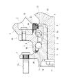
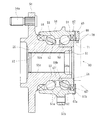
図1は、本発明に係る回転速度検出装置付き車輪用軸受装置の第1の実施形態を示す縦断面図、図2は、図1の要部拡大図である。なお、以下の説明では、車両に組み付けた状態で車両の外側寄りとなる側をアウトボード側(図面左側)、中央寄り側をインボード側(図面右側)という。
Hereinafter, embodiments of the present invention will be described in detail with reference to the drawings.
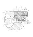
FIG. 1 is a longitudinal sectional view showing a first embodiment of a wheel bearing device with a rotational speed detection device according to the present invention, and FIG. 2 is an enlarged view of a main part of FIG. In the following description, the side closer to the outer side of the vehicle when assembled to the vehicle is referred to as the outboard side (left side in the drawing), and the side closer to the center is referred to as the inboard side (right side in the drawing).
この回転速度検出装置付き車輪用軸受装置は駆動輪用であって、ハブ輪1と複列の転がり軸受2とをユニット化した、所謂第3世代と称される構成を備えている。
複列の転がり軸受2は、外方部材4と内方部材3と複列の転動体(ボール)5、5とを有し、外方部材4は、S53C等の炭素0.40〜0.80wt%を含む中炭素鋼からなり、外周にナックルNに取り付けるための車体取付フランジ4bを一体に有している。内周には複列の外側転走面4a、4aが形成され、高周波焼入れによって表面硬さを54〜64HRCの範囲に硬化層が形成されている。
This wheel bearing device with a rotational speed detection device is for a drive wheel and has a so-called third generation configuration in which the
The double-
一方、ハブ輪1は、アウトボード側の端部に車輪(図示せず)を取り付けるための車輪取付フランジ7を一体に有し、この車輪取付フランジ7の円周等配位置にハブボルト7aが植設されている。また、外周には前記複列の外側転走面4a、4aに対向する一方の内側転走面1aと、この内側転走面1aから軸方向に延びる円筒状の小径段部1bが形成されている。そして、この小径段部1bの端部を径方向外方に塑性変形させて加締部8が形成されている。内輪6はこの小径段部1bに圧入され、その外周に前記複列の外側転走面4a、4aに対向する他方の内側転走面6aが形成されている。また、加締部8によって内輪6はハブ輪1に対して軸方向に固定され、所謂セルフリテイン構造をなしている。これにより、従来のようにナット等で強固に緊締して予圧量を管理する必要がないため、軽量・コンパクト化を図ることができると共に、ハブ輪1の強度・耐久性を向上させ、かつ長期間その予圧量を維持することができる。ここで、内方部材3は、ハブ輪1と、このハブ輪1に圧入された内輪6を指している。
On the other hand, the
外方部材4の外側転走面4a、4aと、これらに対向する複列の内側転走面1a、6a間には複列の転動体5、5がそれぞれ収容され、保持器9、9によって転動自在に保持されている。また、外方部材4の端部にはシール10、11が装着され、軸受内部に封入された潤滑グリースの漏洩と、外部から軸受内部に雨水やダスト等が侵入するのを防止している。
Double
ハブ輪1は、S53C等の炭素0.40〜0.80wt%を含む中炭素鋼からなり、アウトボード側のシール10が摺接するシールランド部から内側転走面1aおよび小径段部1bに亙って高周波焼入れによって表面硬さを54〜64HRCの範囲に硬化層が形成されている。なお、加締部8は、鍛造後の素材表面硬さ25HRC以下の未焼入れ部としている。これにより、車輪取付フランジ7の基部となるシールランド部は耐摩耗性が向上するばかりでなく、車輪取付フランジ7に負荷される回転曲げ荷重に対して充分な機械的強度を有し、ハブ輪1の耐久性が一層向上する。また、加締部8を塑性変形させる時の加工性が向上すると共に、加工時におけるクラック等の発生を防止してその品質の信頼性が向上する。
The
ハブ輪1の内周にはセレーション(またはスプライン)1cが形成され、等速自在継手を構成する外側継手部材12がセレーション1cを介して内嵌されている。そして、外側継手部材12は、その肩部13が前記ハブ輪1の加締部8に突き合わされ、固定ナット14によってハブ輪1と軸方向に一体固定されている。
A serration (or spline) 1c is formed on the inner periphery of the
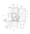
本実施形態では、図2に拡大して示すように、円環状に形成されたセンサホルダ15は外方部材4の端部に装着され、嵌合環16と、この嵌合環16に結合された保持部17とからなる。嵌合環16は、外方部材4の外周に圧入される円筒状の嵌合部16aと、この嵌合部16aから径方向内方に延びる鍔部16bと、この鍔部16bから軸方向に延びる円筒部16cとからなり、全体が円環状に形成されている。この嵌合環16は、耐食性を有するステンレス鋼板等をプレス加工にて形成されている。また、この円筒部16cの周方向複数箇所には穿孔18が形成され、保持部17が合成樹脂で一体モールド成形されている。そして、嵌合環16の鍔部16bを外方部材4の端面に密着させた状態で、センサホルダ15が外方部材4の端部に装着されると共に、シール11がセンサホルダ15のインボード側に配設されている。
In the present embodiment, as shown in an enlarged view in FIG. 2, the
保持部17には、その内部に後述する磁気エンコーダ19に所定の径方向すきまを介して対峙する回転速度センサー20が包埋されている。回転速度センサー20は、ホール素子、磁気抵抗素子(MR素子)等、磁束の流れ方向に応じて特性を変化させる磁気検出素子と、この磁気検出素子の出力波形を整える波形成形回路が組み込まれたICとからなる。
A
インボード側のシール11は、センサホルダ15と内輪6にそれぞれ装着され、断面略L字状に形成された環状の第1および第2のシール板21、22からなり、互いに対向して配置されている。第2のシール板22は、内輪6に外嵌される円筒部22aと、この円筒部22aから軸方向に延びる円筒状の大径段部22bと、この大径段部22bから径方向外方に延びる立板部22cとを有している。この立板部22cの先端部には環状の舌片22dが軸方向に突設され、センサホルダ15の円筒部16cと僅かな径方向すきまを介して対向し、ラビリンスシール23が構成されている。なお、第2のシール板22は、オーステナイト系ステンレス鋼鈑(JIS規格のSUS304系等)、あるいは、防錆処理された冷間圧延鋼鈑(JIS規格のSPCC系等)をプレス加工にて形成されている。
The
一方、第1のシール板21は、センサホルダ15に内嵌される円筒部21aと、この円筒部21aの一端から径方向内方に延びる立板部21bとからなり、サイドリップ24aとグリースリップ24bおよび中間リップ24cとを一体に有するシール部材24が加硫接着されている。このシール部材24はゴム等の弾性部材からなる。
On the other hand, the
ここで、サイドリップ24aは第2のシール板22の立板部22cに摺接し、また、グリースリップ24bおよび中間リップ24cは第2のシール板22の大径段部22bに摺接している。また、第2のシール板22における円筒部22aの外周面にはゴム等のエラストマにフェライト等の磁性体粉が混入された磁気エンコーダ19が一体に加硫接着されている。この磁気エンコーダ19は、周方向に交互に磁極N、Sが着磁され、車輪回転速度の検出用のロータリエンコーダを構成している。
Here, the
このように、本実施形態では、円環状のセンサホルダ15に回転速度センサー20が配設され、この回転速度センサー20のインボード側にシール11が配設されると共に、さらに、このシール11のインボード側にラビリンスシール23が構成されているので、自動車の完成品メーカの組立ラインへの搬送時を含む、ハブ輪1に外側継手部材12を内嵌する以前の状態でも、また、過酷な環境となる実走時においても、磁気エンコーダ19と回転速度センサー20の検出部との間に外部から磁性粉末等の異物が侵入するのを確実に防止することができる。したがって、車輪の回転速度検出の信頼性を格段に向上させることができる。また、径方向のコンパクト化ができると共に、回転速度センサー20等の取り巻きが簡素化でき、組立作業性が一段と向上する。
Thus, in this embodiment, the
なお、本実施形態では、回転速度検出装置として、磁気エンコーダ19と、ホール素子等の磁気検出素子からなる回転速度センサー20とからなるアクティブタイプの回転速度検出装置を例示したが、本発明に係る回転速度検出装置はこれに限らず、例えば、磁気エンコーダと、磁石と巻回された環状のコイル等からなるパッシブタイプであっても良い。
In the present embodiment, as an example of the rotational speed detection apparatus, an active type rotational speed detection apparatus including the
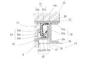
図3は本発明に係る回転速度検出装置付き車輪用軸受装置の第2の実施形態を示す要部拡大図である。なお、この実施形態は、前述した実施形態とラビリンスシールの構成が異なるのみで、その他同一部位、同一部品、あるいは同一の機能を有する部位には同じ符号を付けてその詳細な説明を省略する。 FIG. 3 is an enlarged view of a main part showing a second embodiment of the wheel bearing device with a rotation speed detection device according to the present invention. In this embodiment, only the configuration of the labyrinth seal is different from that of the above-described embodiment, and other parts that are the same, the same parts, or the same function are denoted by the same reference numerals and detailed description thereof is omitted.
インボードが側のシール11’は、外方部材4と内輪6にそれぞれ装着され、断面略L字状に形成された環状の第1および第2のシール板21、22’からなり、互いに対向して配置されている。第2のシール板22’は、内輪6に外嵌される円筒部22aと、この円筒部22aから軸方向に延びる円筒状の大径段部22bと、この大径段部22bから径方向外方に延びる立板部22cとからなる。この立板部22cと第1のシール板21の円筒部21aは僅かな径方向すきまを介して対峙し、ラビリンスシール26が構成されている。
The
ここで、シール11’のさらにインボード側にはシールド25が配設されている。このシールド25は、センサホルダ15に内嵌される第1円筒部25aと、この第1円筒部25aから径方向内方に延びる立板部25bと、この立板部25bから軸方向に延びる第2円筒部25cとからなり、断面が略コの字状に形成されている。そして、この立板部25bと前記第2のシール板22’の立板部22cは僅かな軸方向すきまを介して対向し、ラビリンスシール27が構成されている。さらに、このシールド25の立板部25bと外側継手部材12の肩部13は僅かな径方向すきまを介して対向し、ラビリンスシール28が構成されている。
Here, a
このように、本実施形態では、シール11’のインボード側にシールド25が配設されると共に、シール11’のラビリンスシール26に加え、両者間にラビリンスシール27およびシールド25と外側継手部材12の肩部13の間にラビリンスシール28がそれぞれ構成されているので、自動車の完成品メーカの組立ラインへの搬送時を含む、ハブ輪1に外側継手部材12を内嵌する以前の状態でも、また、過酷な環境となる実走時においても、磁気エンコーダ19と回転速度センサー20の検出部との間に、外部から磁性粉末等の異物が侵入するのを確実に防止することができる。
Thus, in the present embodiment, the
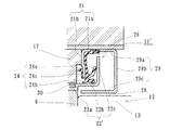
図4は本発明に係る回転速度検出装置付き車輪用軸受装置の第3の実施形態を示す要部拡大図である。なお、この実施形態は、前述した実施形態(図3)の変形例で、シールドの形状が異なるのみで、その他同一部位、同一部品、あるいは同一の機能を有する部位には同じ符号を付けてその詳細な説明を省略する。 FIG. 4 is an enlarged view of a main part showing a third embodiment of a wheel bearing device with a rotational speed detection device according to the present invention. This embodiment is a modification of the above-described embodiment (FIG. 3), except that the shape of the shield is different, and other parts having the same function, the same parts, or the same function are denoted by the same reference numerals. Detailed description is omitted.
シール11’のさらにインボード側にはシールド29が配設されている。このシールド29は、センサホルダ15に内嵌される第1円筒部29aと、この第1円筒部29aから径方向内方に延びる立板部29bと、この立板部29bから軸方向に延びる第2円筒部29cとからなり、断面が略コの字状に形成されている。そして、このシールド29の第2円筒部29cと外側継手部材12の肩部13および内輪6の端面は僅かなすきまを介して対向し、それぞれラビリンスシール28、30が構成されている。
A
このように、本実施形態では、シール11’のインボード側にシールド29が配設されると共に、シール11’のラビリンスシール26に加え、シールド29と外側継手部材12の肩部13および内輪6の端面との間にラビリンスシール28、30がそれぞれ構成されているので、自動車の完成品メーカの組立ラインへの搬送時を含む、ハブ輪1に外側継手部材12を内嵌する以前の状態でも、また、過酷な環境となる実走時においても、磁気エンコーダ19と回転速度センサー20の検出部との間に、外部から磁性粉末等の異物が侵入するのを確実に防止することができる。
Thus, in the present embodiment, the
以上、本発明の実施の形態について説明を行ったが、本発明はこうした実施の形態に何等限定されるものではなく、あくまで例示であって、本発明の要旨を逸脱しない範囲内において、さらに種々なる形態で実施し得ることは勿論のことであり、本発明の範囲は、特許請求の範囲の記載によって示され、さらに特許請求の範囲に記載の均等の意味、および範囲内のすべての変更を含む。 The embodiment of the present invention has been described above, but the present invention is not limited to such an embodiment, and is merely an example, and various modifications can be made without departing from the scope of the present invention. Of course, the scope of the present invention is indicated by the description of the scope of claims, and further, the equivalent meanings described in the scope of claims and all modifications within the scope of the scope of the present invention are included. Including.
本発明に係る回転速度検出装置付き車輪用軸受装置は、内輪回転構造においてあらゆるタイプの回転速度検出装置が内蔵された車輪用軸受装置に適用することができる。 The wheel bearing device with a rotation speed detection device according to the present invention can be applied to a wheel bearing device in which any type of rotation speed detection device is built in the inner ring rotation structure.
1・・・・・・・・・・・・・・・・ハブ輪
1a、6a・・・・・・・・・・・・内側転走面
1b・・・・・・・・・・・・・・・小径段部
1c・・・・・・・・・・・・・・・セレーション
2・・・・・・・・・・・・・・・・複列の転がり軸受
3・・・・・・・・・・・・・・・・内方部材
4・・・・・・・・・・・・・・・・外方部材
4a・・・・・・・・・・・・・・・外側転走面
4b・・・・・・・・・・・・・・・車体取付フランジ
5・・・・・・・・・・・・・・・・転動体
6・・・・・・・・・・・・・・・・内輪
7・・・・・・・・・・・・・・・・車輪取付フランジ
7a・・・・・・・・・・・・・・・ハブボルト
8・・・・・・・・・・・・・・・・加締部
9・・・・・・・・・・・・・・・・保持器
10・・・・・・・・・・・・・・・アウトボード側のシール
11、11’・・・・・・・・・・・・インボード側のシール
12・・・・・・・・・・・・・・・外側継手部材
13・・・・・・・・・・・・・・・肩部
14・・・・・・・・・・・・・・・固定ナット
15・・・・・・・・・・・・・・・センサホルダ
16・・・・・・・・・・・・・・・嵌合環
16a・・・・・・・・・・・・・・嵌合部
16b・・・・・・・・・・・・・・鍔部
16c、21a・・・・・・・・・・円筒部
17・・・・・・・・・・・・・・・保持部
18・・・・・・・・・・・・・・・穿孔
19・・・・・・・・・・・・・・・磁気エンコーダ
20・・・・・・・・・・・・・・・回転速度センサー
21・・・・・・・・・・・・・・・第1のシール板
21b、22c、25b、29b・・立板部
22・・・・・・・・・・・・・・・第2のシール板
22b・・・・・・・・・・・・・・大径段部
22d・・・・・・・・・・・・・・舌片
23、26、27、28、30・・・ラビリンスシール
24・・・・・・・・・・・・・・・シール部材
24a・・・・・・・・・・・・・・サイドリップ
24b・・・・・・・・・・・・・・グリースリップ
24c・・・・・・・・・・・・・・中間リップ
25、29・・・・・・・・・・・・シールド
25a、29a・・・・・・・・・・第1円筒部
25c、29c・・・・・・・・・・第2円筒部
51・・・・・・・・・・・・・・・外方部材
51a・・・・・・・・・・・・・・外側転走面
51b・・・・・・・・・・・・・・車体取付フランジ
52・・・・・・・・・・・・・・・内方部材
53・・・・・・・・・・・・・・・転動体
54・・・・・・・・・・・・・・・車輪取付フランジ
54a・・・・・・・・・・・・・・ハブボルト
55・・・・・・・・・・・・・・・ハブ輪
55a、56a・・・・・・・・・・内側転走面
55b・・・・・・・・・・・・・・小径段部
55c・・・・・・・・・・・・・・セレーション
56・・・・・・・・・・・・・・・内輪
57・・・・・・・・・・・・・・・保持器
58、59・・・・・・・・・・・・シール
60・・・・・・・・・・・・・・・外側継手部材
61・・・・・・・・・・・・・・・ステム部
62・・・・・・・・・・・・・・・第1のシール板
63・・・・・・・・・・・・・・・第2のシール板
63a・・・・・・・・・・・・・・円筒部
63b・・・・・・・・・・・・・・立板部
64・・・・・・・・・・・・・・・磁気エンコーダ
65・・・・・・・・・・・・・・・芯金
66・・・・・・・・・・・・・・・シール部材
66a・・・・・・・・・・・・・・サイドリップ
66b、66c・・・・・・・・・・ラジアルリップ
67・・・・・・・・・・・・・・・嵌合筒
67a・・・・・・・・・・・・・・嵌合筒部
67b・・・・・・・・・・・・・・内向鍔部
68・・・・・・・・・・・・・・・保持部
69・・・・・・・・・・・・・・・センサホルダ
70・・・・・・・・・・・・・・・回転速度センサー
71・・・・・・・・・・・・・・・微小隙間
N・・・・・・・・・・・・・・・・ナックル
1 ・ ・ ・ ・ ・ ・ ・ ・ ・ ・ ・
Claims (6)
一端部に車輪を取り付けるための車輪取付フランジを一体に有し、外周に軸方向に延びる円筒状の小径段部が形成されたハブ輪、およびこのハブ輪の小径段部に圧入された内輪とからなり、外周に前記複列の外側転走面に対向する内側転走面が形成された内方部材と、
前記外方部材および内方部材のそれぞれの転走面間に転動自在に収容された複列の転動体と、
前記内輪に外嵌されたエンコーダと、このエンコーダに対向するように前記外方部材の端部に装着された円環状のセンサホルダと、
このセンサホルダに一体モールドされ、前記エンコーダに所定の径方向すきまを介して対峙する回転速度センサーと、を備えた回転速度検出装置付き車輪用軸受装置において、
前記エンコーダが円環状をなし、その円周方向に関する特性が交互にかつ等間隔に変化するように構成されると共に、このエンコーダのインボード側にシールが配設され、このシールが、前記センサホルダと内輪にそれぞれ装着され、互いに対向して配置された環状の第1および第2のシール板からなり、前記エンコーダがこの第2のシール板に一体に設けられていることを特徴とする回転速度検出装置付き車輪用軸受装置。 An outer member integrally having a vehicle body mounting flange for mounting to a suspension device on the outer periphery, and a double row outer rolling surface formed on the inner periphery;
A hub ring integrally having a wheel mounting flange for mounting a wheel at one end, and having a cylindrical small-diameter step portion extending in the axial direction on the outer periphery, and an inner ring press-fitted into the small-diameter step portion of the hub ring; An inner member formed on the outer periphery with an inner rolling surface facing the outer rolling surface of the double row,
A double row rolling element housed so as to be freely rollable between the rolling surfaces of the outer member and the inner member;
An encoder externally fitted to the inner ring, and an annular sensor holder attached to an end of the outer member so as to face the encoder;
In the wheel bearing device with a rotational speed detection device, which is integrally molded with the sensor holder and includes a rotational speed sensor facing the encoder via a predetermined radial clearance,
The encoder has an annular shape, and the characteristic in the circumferential direction changes alternately and at equal intervals, and a seal is disposed on the inboard side of the encoder. And an annular first seal plate and a second seal plate disposed opposite to each other, and the encoder is provided integrally with the second seal plate. Wheel bearing device with detection device.
Priority Applications (2)
| Application Number | Priority Date | Filing Date | Title |
|---|---|---|---|
| JP2004115145A JP2005299764A (en) | 2004-04-09 | 2004-04-09 | Bearing device for wheel with rotation speed detection device |
| US11/101,351 US7618194B2 (en) | 2004-04-09 | 2005-04-07 | Wheel bearing apparatus incorporated with a wheel speed detecting apparatus |
Applications Claiming Priority (1)
| Application Number | Priority Date | Filing Date | Title |
|---|---|---|---|
| JP2004115145A JP2005299764A (en) | 2004-04-09 | 2004-04-09 | Bearing device for wheel with rotation speed detection device |
Publications (2)
| Publication Number | Publication Date |
|---|---|
| JP2005299764A true JP2005299764A (en) | 2005-10-27 |
| JP2005299764A5 JP2005299764A5 (en) | 2006-11-16 |
Family
ID=35331543
Family Applications (1)
| Application Number | Title | Priority Date | Filing Date |
|---|---|---|---|
| JP2004115145A Pending JP2005299764A (en) | 2004-04-09 | 2004-04-09 | Bearing device for wheel with rotation speed detection device |
Country Status (1)
| Country | Link |
|---|---|
| JP (1) | JP2005299764A (en) |
Cited By (5)
| Publication number | Priority date | Publication date | Assignee | Title |
|---|---|---|---|---|
| WO2008084613A1 (en) * | 2007-01-09 | 2008-07-17 | Ntn Corporation | Seal device with sensor and bearing device for wheel |
| JP2008304011A (en) * | 2007-06-08 | 2008-12-18 | Jtekt Corp | Hub unit |
| WO2008152987A1 (en) * | 2007-06-08 | 2008-12-18 | Jtekt Corporation | Hub unit |
| WO2009005085A1 (en) * | 2007-07-03 | 2009-01-08 | Jtekt Corporation | Sensor device, and rolling bearing device with sensor |
| JP2009008599A (en) * | 2007-06-29 | 2009-01-15 | Jtekt Corp | Rotation speed detector |
-
2004
- 2004-04-09 JP JP2004115145A patent/JP2005299764A/en active Pending
Cited By (5)
| Publication number | Priority date | Publication date | Assignee | Title |
|---|---|---|---|---|
| WO2008084613A1 (en) * | 2007-01-09 | 2008-07-17 | Ntn Corporation | Seal device with sensor and bearing device for wheel |
| JP2008304011A (en) * | 2007-06-08 | 2008-12-18 | Jtekt Corp | Hub unit |
| WO2008152987A1 (en) * | 2007-06-08 | 2008-12-18 | Jtekt Corporation | Hub unit |
| JP2009008599A (en) * | 2007-06-29 | 2009-01-15 | Jtekt Corp | Rotation speed detector |
| WO2009005085A1 (en) * | 2007-07-03 | 2009-01-08 | Jtekt Corporation | Sensor device, and rolling bearing device with sensor |
Similar Documents
| Publication | Publication Date | Title |
|---|---|---|
| JP4679192B2 (en) | Wheel bearing device with rotation speed detector | |
| JP4628049B2 (en) | Wheel bearing device with rotation speed detector | |
| JP4784967B2 (en) | Wheel bearing device with rotation speed detector | |
| JP4375790B2 (en) | Wheel bearing device with rotation speed detector | |
| JP2006112919A (en) | Bearing device for wheel with rotational speed sensor | |
| JP4748775B2 (en) | Wheel bearing device with rotation speed detector | |
| JP4498052B2 (en) | Wheel bearing device with rotation speed detector | |
| JP2007010480A (en) | Bearing apparatus for wheel with rotation speed detection device | |
| JP2006284402A (en) | Bearing device for wheel with rotation speed detection device | |
| JP4628395B2 (en) | Wheel bearing device with rotation speed detector | |
| JP2005299764A (en) | Bearing device for wheel with rotation speed detection device | |
| JP4726042B2 (en) | Wheel bearing device with rotation speed detector | |
| JP4964611B2 (en) | Wheel bearing device with rotation speed detector | |
| JP4628053B2 (en) | Wheel bearing device with rotation speed detector | |
| JP2008151727A (en) | Rotation speed detector and wheel bearing device with the detector | |
| JP2008180544A (en) | Bearing device for wheel with revolution detector | |
| JP2007232731A (en) | Bearing device for wheel with rotation speed detector | |
| JP4803572B2 (en) | Magnetic encoder and wheel bearing device provided with the same | |
| JP2008024051A (en) | Bearing device for driving wheel | |
| JP2006308396A (en) | Bearing device for wheel with rotating speed detecting device | |
| JP2009138781A (en) | Wheel bearing device with rotating speed detecting device | |
| JP2006349061A (en) | Bearing device with rotational speed detector for wheel | |
| JP2009030756A (en) | Bearing device for wheel with rotation speed detection device | |
| JP2008261463A (en) | Bearing device for wheel with rotational speed detector | |
| JP2008151623A (en) | Sensor holder and wheel-use bearing device having rotation speed detector with the same sensor holder built-in |
Legal Events
| Date | Code | Title | Description |
|---|---|---|---|
| A521 | Written amendment |
Free format text: JAPANESE INTERMEDIATE CODE: A523 Effective date: 20060928 |
|
| A621 | Written request for application examination |
Effective date: 20060928 Free format text: JAPANESE INTERMEDIATE CODE: A621 |
|
| A871 | Explanation of circumstances concerning accelerated examination |
Effective date: 20060928 Free format text: JAPANESE INTERMEDIATE CODE: A871 |
|
| A975 | Report on accelerated examination |
Effective date: 20061013 Free format text: JAPANESE INTERMEDIATE CODE: A971005 |
|
| A131 | Notification of reasons for refusal |
Free format text: JAPANESE INTERMEDIATE CODE: A131 Effective date: 20061114 |
|
| A521 | Written amendment |
Free format text: JAPANESE INTERMEDIATE CODE: A523 Effective date: 20061226 |
|
| A131 | Notification of reasons for refusal |
Free format text: JAPANESE INTERMEDIATE CODE: A131 Effective date: 20070206 |
|
| A521 | Written amendment |
Free format text: JAPANESE INTERMEDIATE CODE: A523 Effective date: 20070409 |
|
| A02 | Decision of refusal |
Free format text: JAPANESE INTERMEDIATE CODE: A02 Effective date: 20070515 |
|
| A521 | Written amendment |
Effective date: 20070717 Free format text: JAPANESE INTERMEDIATE CODE: A523 |
|
| A911 | Transfer of reconsideration by examiner before appeal (zenchi) |
Effective date: 20070723 Free format text: JAPANESE INTERMEDIATE CODE: A911 |
|
| A912 | Removal of reconsideration by examiner before appeal (zenchi) |
Effective date: 20070907 Free format text: JAPANESE INTERMEDIATE CODE: A912 |