JP2010000890A - ポジションスイッチ装置 - Google Patents
ポジションスイッチ装置 Download PDFInfo
- Publication number
- JP2010000890A JP2010000890A JP2008161111A JP2008161111A JP2010000890A JP 2010000890 A JP2010000890 A JP 2010000890A JP 2008161111 A JP2008161111 A JP 2008161111A JP 2008161111 A JP2008161111 A JP 2008161111A JP 2010000890 A JP2010000890 A JP 2010000890A
- Authority
- JP
- Japan
- Prior art keywords
- double
- movable contact
- shift
- mode
- contacts
- Prior art date
- Legal status (The legal status is an assumption and is not a legal conclusion. Google has not performed a legal analysis and makes no representation as to the accuracy of the status listed.)
- Granted
Links
- 239000000758 substrate Substances 0.000 claims description 13
- 244000145845 chattering Species 0.000 abstract description 3
- 238000001514 detection method Methods 0.000 description 8
- 230000005540 biological transmission Effects 0.000 description 7
- 239000011347 resin Substances 0.000 description 2
- 229920005989 resin Polymers 0.000 description 2
- RYGMFSIKBFXOCR-UHFFFAOYSA-N Copper Chemical compound [Cu] RYGMFSIKBFXOCR-UHFFFAOYSA-N 0.000 description 1
- 239000011889 copper foil Substances 0.000 description 1
- 239000000446 fuel Substances 0.000 description 1
- 238000000059 patterning Methods 0.000 description 1
- 230000001105 regulatory effect Effects 0.000 description 1
Images


Classifications
-
- F—MECHANICAL ENGINEERING; LIGHTING; HEATING; WEAPONS; BLASTING
- F16—ENGINEERING ELEMENTS AND UNITS; GENERAL MEASURES FOR PRODUCING AND MAINTAINING EFFECTIVE FUNCTIONING OF MACHINES OR INSTALLATIONS; THERMAL INSULATION IN GENERAL
- F16H—GEARING
- F16H59/00—Control inputs to control units of change-speed- or reversing-gearings for conveying rotary motion
- F16H59/02—Selector apparatus
- F16H59/0204—Selector apparatus for automatic transmissions with means for range selection and manual shifting, e.g. range selector with tiptronic
Landscapes
- Engineering & Computer Science (AREA)
- General Engineering & Computer Science (AREA)
- Mechanical Engineering (AREA)
- Arrangement Or Mounting Of Control Devices For Change-Speed Gearing (AREA)
Abstract
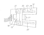
【解決手段】シフトレバー装置のリテーナ1の片側に配置されたスイッチボックス10の内部に、表裏とも同一位置に機能が同一の複数の接点S1〜S5を形成した両面基板12と、この両面基板12の両面に同時に接触しながらスライドできる可動コンタクトプレート13とを収納する。またこのスイッチボックス10の側方には、シフトレバー4のシフト方向の動きに追従して可動コンタクトプレート13をシフト方向にスライドさせるコントロールレバー18を配置する。
【選択図】図3
Description
図1は本発明のポジションスイッチ装置が組み込まれたシフトレバー装置の全体斜視図、図2はその平面図、図3は内部構造を示す断面図である。これらの図において、1はボックス型をした樹脂製のリテーナであり、その内部下方にはシフト操作用の軸2が配置されている。またこの軸2の中心部にはほぼ水平にセレクト操作用の軸3が貫通しており、シフトレバー4の下端がこの軸3に枢着されている。この構造により、シフトレバー4は車体前後方向のシフト方向及び車体幅方向のセレクト方向の何れの方向にも操作することができる。
2 シフト操作用の軸
3 セレクト操作用の軸
4 シフトレバー
5 ゲートプレート
6 ゲート溝
10 スイッチボックス
11 コントロールレバー
12 両面基板
13 可動コンタクトプレート
14 スリット
15 モード検出スイッチ
16 長孔
17 突起
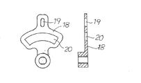
18 コントロールレバー
19 縦長孔
20 扇形の貫通孔
21 突起
Claims (5)
- シフトレバー装置のリテーナの片側に配置されたスイッチボックスの内部に、表裏とも同一位置に機能が同一の複数の接点を形成した両面基板と、この両面基板の両面に同時に接触しながらスライドできる可動コンタクトプレートとを収納するとともに、このスイッチボックスの側方には、シフトレバーのシフト方向の動きに追従して可動コンタクトプレートをシフト方向にスライドさせるコントロールレバーを配置したことを特徴とするポジションスイッチ装置。
- 両面基板の複数の接点が、シフト方向に直線的に配置されたことを特徴とする請求項1記載のポジションスイッチ装置。
- 両面基板の複数の接点が、ATモードのR、N、Dの各ポジションに対応する接点と、MTモードのM+、M、M−の各ポジションに対応する接点とを含み、かつそれらの一部を共用した接点を持つことを特徴とする請求項1記載のポジションスイッチ装置。
- 両面基板は中央にスリットが形成されたものであり、可動コンタクトプレートはこのスリットを介して両面基板の両面に延びていることを特徴とする請求項1記載のポジションスイッチ装置。
- 可動コンタクトプレートは、スイッチボックスに形成された長孔から突出する突起を備えたものであり、コントロールレバーがこの突起と係合して可動コンタクトプレートをシフト方向にスライドさせることを特徴とする請求項1記載のポジションスイッチ装置。
Priority Applications (1)
| Application Number | Priority Date | Filing Date | Title |
|---|---|---|---|
| JP2008161111A JP5137197B2 (ja) | 2008-06-20 | 2008-06-20 | ポジションスイッチ装置 |
Applications Claiming Priority (1)
| Application Number | Priority Date | Filing Date | Title |
|---|---|---|---|
| JP2008161111A JP5137197B2 (ja) | 2008-06-20 | 2008-06-20 | ポジションスイッチ装置 |
Publications (2)
| Publication Number | Publication Date |
|---|---|
| JP2010000890A true JP2010000890A (ja) | 2010-01-07 |
| JP5137197B2 JP5137197B2 (ja) | 2013-02-06 |
Family
ID=41582969
Family Applications (1)
| Application Number | Title | Priority Date | Filing Date |
|---|---|---|---|
| JP2008161111A Active JP5137197B2 (ja) | 2008-06-20 | 2008-06-20 | ポジションスイッチ装置 |
Country Status (1)
| Country | Link |
|---|---|
| JP (1) | JP5137197B2 (ja) |
Cited By (2)
| Publication number | Priority date | Publication date | Assignee | Title |
|---|---|---|---|---|
| DE112010005086T5 (de) | 2010-01-06 | 2012-11-15 | Canon Kabushiki Kaisha | Kameraplattformsystem |
| WO2018038274A1 (ja) * | 2016-08-26 | 2018-03-01 | 株式会社東海理化電機製作所 | シフト装置 |
Citations (5)
| Publication number | Priority date | Publication date | Assignee | Title |
|---|---|---|---|---|
| JPS56144444U (ja) * | 1980-03-31 | 1981-10-31 | ||
| JPH0735225A (ja) * | 1993-05-19 | 1995-02-07 | Matsushita Electric Works Ltd | ポジション信号発生スイッチ |
| JPH10159970A (ja) * | 1996-11-29 | 1998-06-16 | Aisin Aw Co Ltd | ニュートラルスタートスイッチ一体型電子制御ユニット |
| JP2000108707A (ja) * | 1998-08-03 | 2000-04-18 | Kojima Press Co Ltd | シフトレバー装置 |
| JP2000127791A (ja) * | 1998-10-21 | 2000-05-09 | Nissan Motor Co Ltd | 自動変速機のインヒビタスイッチ |
-
2008
- 2008-06-20 JP JP2008161111A patent/JP5137197B2/ja active Active
Patent Citations (5)
| Publication number | Priority date | Publication date | Assignee | Title |
|---|---|---|---|---|
| JPS56144444U (ja) * | 1980-03-31 | 1981-10-31 | ||
| JPH0735225A (ja) * | 1993-05-19 | 1995-02-07 | Matsushita Electric Works Ltd | ポジション信号発生スイッチ |
| JPH10159970A (ja) * | 1996-11-29 | 1998-06-16 | Aisin Aw Co Ltd | ニュートラルスタートスイッチ一体型電子制御ユニット |
| JP2000108707A (ja) * | 1998-08-03 | 2000-04-18 | Kojima Press Co Ltd | シフトレバー装置 |
| JP2000127791A (ja) * | 1998-10-21 | 2000-05-09 | Nissan Motor Co Ltd | 自動変速機のインヒビタスイッチ |
Cited By (2)
| Publication number | Priority date | Publication date | Assignee | Title |
|---|---|---|---|---|
| DE112010005086T5 (de) | 2010-01-06 | 2012-11-15 | Canon Kabushiki Kaisha | Kameraplattformsystem |
| WO2018038274A1 (ja) * | 2016-08-26 | 2018-03-01 | 株式会社東海理化電機製作所 | シフト装置 |
Also Published As
| Publication number | Publication date |
|---|---|
| JP5137197B2 (ja) | 2013-02-06 |
Similar Documents
| Publication | Publication Date | Title |
|---|---|---|
| KR100226121B1 (ko) | 차량의 변속조작장치 | |
| CA2875921C (en) | Shift device for vehicle | |
| US20190353241A1 (en) | Shift control apparatus for electronic shift system | |
| US20180172140A1 (en) | Vehicle shift lever assembly | |
| JP4500327B2 (ja) | シフト装置 | |
| JP5842001B2 (ja) | シフト切り替え装置 | |
| EP3499093B1 (en) | Gearshift control mechanism, automobile, and gear control method | |
| EP3054196B1 (en) | Shift device | |
| JP6060962B2 (ja) | 車両用シフト装置 | |
| JP5137197B2 (ja) | ポジションスイッチ装置 | |
| JP6610633B2 (ja) | 車両用シフタ装置 | |
| JP2007045390A (ja) | シフト装置 | |
| JP6610634B2 (ja) | 車両用シフタ装置 | |
| JP5033105B2 (ja) | 位置検出装置 | |
| JP5880397B2 (ja) | 車両のシフト装置 | |
| JP6003785B2 (ja) | 車両のシフト装置 | |
| US10941854B2 (en) | Operating device | |
| JP6595107B2 (ja) | 車両用入力装置 | |
| JP4969343B2 (ja) | 車両用変速操作装置 | |
| KR101575224B1 (ko) | 자동차용 메뉴얼모드 스위치 | |
| JP2013001368A (ja) | シフトレンジ操作装置 | |
| JP3705315B2 (ja) | 自動変速機の変速操作入力装置 | |
| EP3431317B1 (en) | Shift device | |
| JP6079769B2 (ja) | 車両用シフト装置 | |
| CN111911617B (zh) | 用于车辆的换挡杆装置 |
Legal Events
| Date | Code | Title | Description |
|---|---|---|---|
| A621 | Written request for application examination |
Free format text: JAPANESE INTERMEDIATE CODE: A621 Effective date: 20110510 |
|
| A977 | Report on retrieval |
Free format text: JAPANESE INTERMEDIATE CODE: A971007 Effective date: 20120529 |
|
| A131 | Notification of reasons for refusal |
Free format text: JAPANESE INTERMEDIATE CODE: A131 Effective date: 20120807 |
|
| A521 | Request for written amendment filed |
Free format text: JAPANESE INTERMEDIATE CODE: A523 Effective date: 20121004 |
|
| TRDD | Decision of grant or rejection written | ||
| A01 | Written decision to grant a patent or to grant a registration (utility model) |
Free format text: JAPANESE INTERMEDIATE CODE: A01 Effective date: 20121109 |
|
| A01 | Written decision to grant a patent or to grant a registration (utility model) |
Free format text: JAPANESE INTERMEDIATE CODE: A01 |
|
| A61 | First payment of annual fees (during grant procedure) |
Free format text: JAPANESE INTERMEDIATE CODE: A61 Effective date: 20121109 |
|
| R150 | Certificate of patent or registration of utility model |
Ref document number: 5137197 Country of ref document: JP Free format text: JAPANESE INTERMEDIATE CODE: R150 Free format text: JAPANESE INTERMEDIATE CODE: R150 |
|
| FPAY | Renewal fee payment (event date is renewal date of database) |
Free format text: PAYMENT UNTIL: 20151122 Year of fee payment: 3 |
|
| R250 | Receipt of annual fees |
Free format text: JAPANESE INTERMEDIATE CODE: R250 |
|
| R250 | Receipt of annual fees |
Free format text: JAPANESE INTERMEDIATE CODE: R250 |
|
| R250 | Receipt of annual fees |
Free format text: JAPANESE INTERMEDIATE CODE: R250 |
|
| R250 | Receipt of annual fees |
Free format text: JAPANESE INTERMEDIATE CODE: R250 |