JP2007008341A - 車載用コンビネーションスイッチ - Google Patents
車載用コンビネーションスイッチ Download PDFInfo
- Publication number
- JP2007008341A JP2007008341A JP2005192366A JP2005192366A JP2007008341A JP 2007008341 A JP2007008341 A JP 2007008341A JP 2005192366 A JP2005192366 A JP 2005192366A JP 2005192366 A JP2005192366 A JP 2005192366A JP 2007008341 A JP2007008341 A JP 2007008341A
- Authority
- JP
- Japan
- Prior art keywords
- switch
- housing
- snap
- switch box
- piece
- Prior art date
- Legal status (The legal status is an assumption and is not a legal conclusion. Google has not performed a legal analysis and makes no representation as to the accuracy of the status listed.)
- Withdrawn
Links
Images
Classifications
-
- B—PERFORMING OPERATIONS; TRANSPORTING
- B60—VEHICLES IN GENERAL
- B60Q—ARRANGEMENT OF SIGNALLING OR LIGHTING DEVICES, THE MOUNTING OR SUPPORTING THEREOF OR CIRCUITS THEREFOR, FOR VEHICLES IN GENERAL
- B60Q1/00—Arrangement of optical signalling or lighting devices, the mounting or supporting thereof or circuits therefor
- B60Q1/02—Arrangement of optical signalling or lighting devices, the mounting or supporting thereof or circuits therefor the devices being primarily intended to illuminate the way ahead or to illuminate other areas of way or environments
- B60Q1/04—Arrangement of optical signalling or lighting devices, the mounting or supporting thereof or circuits therefor the devices being primarily intended to illuminate the way ahead or to illuminate other areas of way or environments the devices being headlights
- B60Q1/14—Arrangement of optical signalling or lighting devices, the mounting or supporting thereof or circuits therefor the devices being primarily intended to illuminate the way ahead or to illuminate other areas of way or environments the devices being headlights having dimming means
- B60Q1/1446—Arrangement of optical signalling or lighting devices, the mounting or supporting thereof or circuits therefor the devices being primarily intended to illuminate the way ahead or to illuminate other areas of way or environments the devices being headlights having dimming means controlled by mechanically actuated switches
- B60Q1/1453—Hand actuated switches
- B60Q1/1461—Multifunction switches for dimming headlights and controlling additional devices, e.g. for controlling direction indicating lights
Landscapes
- Engineering & Computer Science (AREA)
- Mechanical Engineering (AREA)
- Switch Cases, Indication, And Locking (AREA)
- Switches With Compound Operations (AREA)
Abstract
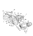
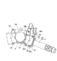
【解決手段】 車載用コンビネーションスイッチ1は、ステアリングシャフトが挿通される開口20を有するハウジング2と、このハウジング2内に側方から挿入して装着されるスイッチボックス30ならびに該スイッチボックス30の外方へ突出する操作杆31を有するストークスイッチ3とを備えており、スイッチボックス30の外壁32に突設したスナップ片33が、ハウジング2の壁部23に開設した係止孔26にスナップ嵌合されている。ハウジング2内にはスイッチボックス30の挿入方向先端部30aと対向する位置に弾性片27が突設されており、この弾性片27を該先端部30aに弾接させることによってスナップ片33の爪部33aを係止孔26の周縁部に弾接させている。
【選択図】 図1
Description
2 ハウジング
3 ストークスイッチ
20 開口
21 収納空間
21a 挿入口
23 壁部
24 幅広ガイド溝
25 幅狭ガイド溝
26 係止孔
27 弾性片
27a 先端押圧部
30 スイッチボックス
30a 挿入方向先端部
30b 凹所
31 操作杆
32 外壁
33 スナップ片
33a 爪部
34 ガイド突起
L 中心線
Claims (3)
- ステアリングシャフトが挿通される開口を有して車体側のステータ部材に固定されるハウジングと、スイッチボックスの外方へ突出する操作杆を有するストークスイッチとを備え、前記スイッチボックスを前記ハウジング内に側方から挿入することにより、前記スイッチボックスの外壁に突設したスナップ片を前記ハウジングの壁部に開設した係止孔にスナップ結合させるようにした車載用コンビネーションスイッチであって、
前記ハウジング内に弾性片を突設し、この弾性片を前記スイッチボックスの挿入方向先端部に弾接させることにより、前記スナップ片の爪部を前記係止孔の周縁部に弾接させたことを特徴とする車載用コンビネーションスイッチ。 - 請求項1の記載において、前記スナップ片を前記スイッチボックスの略平行な一対の外壁にそれぞれ突設すると共に、前記係止孔を前記ハウジングの略平行な一対の壁部にそれぞれ開設したことを特徴とする車載用コンビネーションスイッチ。
- 請求項1または2の記載において、前記スイッチボックスの挿入方向先端部に凹所を設け、この凹所内に前記弾性片を入り込ませたことを特徴とする車載用コンビネーションスイッチ。
Priority Applications (3)
| Application Number | Priority Date | Filing Date | Title |
|---|---|---|---|
| JP2005192366A JP2007008341A (ja) | 2005-06-30 | 2005-06-30 | 車載用コンビネーションスイッチ |
| US11/475,436 US7279648B2 (en) | 2005-06-30 | 2006-06-26 | Automotive combination switch |
| CNB2006100958533A CN100533621C (zh) | 2005-06-30 | 2006-06-30 | 车载用组合开关 |
Applications Claiming Priority (1)
| Application Number | Priority Date | Filing Date | Title |
|---|---|---|---|
| JP2005192366A JP2007008341A (ja) | 2005-06-30 | 2005-06-30 | 車載用コンビネーションスイッチ |
Publications (2)
| Publication Number | Publication Date |
|---|---|
| JP2007008341A true JP2007008341A (ja) | 2007-01-18 |
| JP2007008341A5 JP2007008341A5 (ja) | 2007-10-11 |
Family
ID=37588170
Family Applications (1)
| Application Number | Title | Priority Date | Filing Date |
|---|---|---|---|
| JP2005192366A Withdrawn JP2007008341A (ja) | 2005-06-30 | 2005-06-30 | 車載用コンビネーションスイッチ |
Country Status (3)
| Country | Link |
|---|---|
| US (1) | US7279648B2 (ja) |
| JP (1) | JP2007008341A (ja) |
| CN (1) | CN100533621C (ja) |
Cited By (1)
| Publication number | Priority date | Publication date | Assignee | Title |
|---|---|---|---|---|
| JP2016001565A (ja) * | 2014-06-12 | 2016-01-07 | アルプス電気株式会社 | ケース付き機構装置 |
Families Citing this family (3)
| Publication number | Priority date | Publication date | Assignee | Title |
|---|---|---|---|---|
| JP2009214593A (ja) * | 2008-03-07 | 2009-09-24 | Alps Electric Co Ltd | ターンシグナルスイッチ装置 |
| JP7246976B2 (ja) * | 2019-03-07 | 2023-03-28 | 東洋電装株式会社 | レバースイッチ |
| JP7269758B2 (ja) * | 2019-03-07 | 2023-05-09 | 東洋電装株式会社 | レバースイッチ |
Citations (4)
| Publication number | Priority date | Publication date | Assignee | Title |
|---|---|---|---|---|
| JPH07320595A (ja) * | 1994-05-27 | 1995-12-08 | Yuhshin Co Ltd | スイッチ装置 |
| JPH09129092A (ja) * | 1995-11-01 | 1997-05-16 | Niles Parts Co Ltd | 回転コネクタを備えたコンビネーションスイッチ装置 |
| JP2002352671A (ja) * | 2001-05-22 | 2002-12-06 | Niles Parts Co Ltd | 車両用コンビネーションスイッチ |
| JP2003137049A (ja) * | 2001-10-31 | 2003-05-14 | Tokai Rika Co Ltd | 自動車用スイッチ装置 |
Family Cites Families (5)
| Publication number | Priority date | Publication date | Assignee | Title |
|---|---|---|---|---|
| JPH10241504A (ja) * | 1997-02-24 | 1998-09-11 | Yazaki Corp | ステアリング用信号伝達装置 |
| JP3503875B2 (ja) * | 1998-11-25 | 2004-03-08 | 矢崎総業株式会社 | コンビネーションスイッチ装置 |
| JP2001206143A (ja) * | 2000-01-24 | 2001-07-31 | Yazaki Corp | ステアリング用信号伝達装置 |
| US6501033B2 (en) * | 2000-05-26 | 2002-12-31 | Methode Electronics, Inc. | Serviceable steering column module (SCM) |
| JP2003132753A (ja) | 2001-10-22 | 2003-05-09 | Niles Parts Co Ltd | スイッチ接点構造 |
-
2005
- 2005-06-30 JP JP2005192366A patent/JP2007008341A/ja not_active Withdrawn
-
2006
- 2006-06-26 US US11/475,436 patent/US7279648B2/en active Active
- 2006-06-30 CN CNB2006100958533A patent/CN100533621C/zh active Active
Patent Citations (4)
| Publication number | Priority date | Publication date | Assignee | Title |
|---|---|---|---|---|
| JPH07320595A (ja) * | 1994-05-27 | 1995-12-08 | Yuhshin Co Ltd | スイッチ装置 |
| JPH09129092A (ja) * | 1995-11-01 | 1997-05-16 | Niles Parts Co Ltd | 回転コネクタを備えたコンビネーションスイッチ装置 |
| JP2002352671A (ja) * | 2001-05-22 | 2002-12-06 | Niles Parts Co Ltd | 車両用コンビネーションスイッチ |
| JP2003137049A (ja) * | 2001-10-31 | 2003-05-14 | Tokai Rika Co Ltd | 自動車用スイッチ装置 |
Cited By (1)
| Publication number | Priority date | Publication date | Assignee | Title |
|---|---|---|---|---|
| JP2016001565A (ja) * | 2014-06-12 | 2016-01-07 | アルプス電気株式会社 | ケース付き機構装置 |
Also Published As
| Publication number | Publication date |
|---|---|
| CN100533621C (zh) | 2009-08-26 |
| US20070000761A1 (en) | 2007-01-04 |
| US7279648B2 (en) | 2007-10-09 |
| CN1895935A (zh) | 2007-01-17 |
Similar Documents
| Publication | Publication Date | Title |
|---|---|---|
| JP2003086306A (ja) | カード用コネクタ | |
| JP2008293810A (ja) | コネクタ | |
| KR100826384B1 (ko) | 속결단자장치 | |
| JP2007008341A (ja) | 車載用コンビネーションスイッチ | |
| KR101119752B1 (ko) | 커넥터 | |
| US6172314B1 (en) | Automotive combination switch | |
| US6459058B1 (en) | Operating device having operating button adapted to slide in housing while being pushed to effect switching operation | |
| JP2012015002A (ja) | スイッチ装置 | |
| JP2011210521A (ja) | スイッチ部材及び車載用室内照明装置 | |
| JP2004171911A (ja) | コネクタ | |
| JP4464882B2 (ja) | 電気装置の操作機構 | |
| JP2010113978A (ja) | 自動車室内用のプッシュ式スイッチ | |
| US20090223790A1 (en) | Turn signal switch device | |
| JP2007207563A (ja) | 電気装置の操作機構 | |
| US20140000404A1 (en) | Shift lever device | |
| JP5096967B2 (ja) | 車室内照明装置用ケース | |
| JP4354901B2 (ja) | 係合構造 | |
| JP6248587B2 (ja) | スイッチ | |
| US9550451B2 (en) | Case-equipped mechanism device | |
| JP2004104947A (ja) | クロックスプリングの取付け構造 | |
| JP2013192344A (ja) | 自動車用室内照明灯のハウジングとその電線ホルダ | |
| JP2014096960A (ja) | 電子ユニット取付構造 | |
| JP4741358B2 (ja) | 自動変速機用コントロールスイッチ | |
| JP2005267929A (ja) | スイッチ装置 | |
| JP4920338B2 (ja) | スイッチ装置の取付構造 |
Legal Events
| Date | Code | Title | Description |
|---|---|---|---|
| A521 | Written amendment |
Free format text: JAPANESE INTERMEDIATE CODE: A523 Effective date: 20070827 |
|
| A621 | Written request for application examination |
Free format text: JAPANESE INTERMEDIATE CODE: A621 Effective date: 20070827 |
|
| A977 | Report on retrieval |
Free format text: JAPANESE INTERMEDIATE CODE: A971007 Effective date: 20100415 |
|
| A131 | Notification of reasons for refusal |
Free format text: JAPANESE INTERMEDIATE CODE: A131 Effective date: 20100420 |
|
| A761 | Written withdrawal of application |
Free format text: JAPANESE INTERMEDIATE CODE: A761 Effective date: 20100527 |


