JP2006332175A - トリミング回路及び電子回路 - Google Patents
トリミング回路及び電子回路 Download PDFInfo
- Publication number
- JP2006332175A JP2006332175A JP2005150872A JP2005150872A JP2006332175A JP 2006332175 A JP2006332175 A JP 2006332175A JP 2005150872 A JP2005150872 A JP 2005150872A JP 2005150872 A JP2005150872 A JP 2005150872A JP 2006332175 A JP2006332175 A JP 2006332175A
- Authority
- JP
- Japan
- Prior art keywords
- resistance value
- circuit
- runit
- unit
- transistor
- Prior art date
- Legal status (The legal status is an assumption and is not a legal conclusion. Google has not performed a legal analysis and makes no representation as to the accuracy of the status listed.)
- Pending
Links
Images


Classifications
-
- H—ELECTRICITY
- H01—ELECTRIC ELEMENTS
- H01C—RESISTORS
- H01C10/00—Adjustable resistors
- H01C10/14—Adjustable resistors adjustable by auxiliary driving means
-
- H—ELECTRICITY
- H01—ELECTRIC ELEMENTS
- H01C—RESISTORS
- H01C10/00—Adjustable resistors
- H01C10/06—Adjustable resistors adjustable by short-circuiting different amounts of the resistive element
Landscapes
- Engineering & Computer Science (AREA)
- Microelectronics & Electronic Packaging (AREA)
- Semiconductor Integrated Circuits (AREA)
Abstract
【解決手段】 トリミング回路は、直列に接続された複数のユニットを有する。Runit/2、Runit/4、Runit/8、Runit/16の調整抵抗値を変化させるユニットは、トランジスタTrnと、これに直列に接続されている抵抗値Rtの直列抵抗回路と、これらトランジスタTrn及び直列抵抗回路に、並列に接続されている抵抗値Rmの並列抵抗回路とから構成されている。これらユニットにおいては、トランジスタTrnがオフしたときの抵抗値Rmと、トランジスタTrnがオンしたときのユニット全体の抵抗値との差が、調整抵抗値となるように、抵抗値Rm,Rtを決定する。
【選択図】 図3
Description
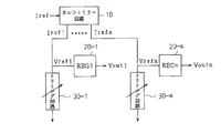
1〜20−nにそれぞれ接続されており、供給された基準電流Irefに基づいて出力電流
(Iref1〜Irefn)がレギュレータ20−1〜20−nに供給される。カレントミラー回路10とレギュレータ20−1〜20−nとを接続するラインには、トリミング回路30−1〜30−nが接続されている。このトリミング回路30−1〜30−nの抵抗値を微調整することにより、各レギュレータ20−1〜20−nのそれぞれに供給される基準電圧Vref1〜Vrefnが調整されている。そして、各レギュレータ20−1〜20−nは、基準電圧Vref1〜Vrefnを用いて各動作回路(図示せず)に、必要に応じて調整した電圧Vout1〜Voutnを供給する。
本実施形態のトリミング回路は、抵抗値Rxのベース抵抗回路に対してユニットu1〜u6が直列に接続されて構成されている。このベース抵抗回路は、カレントミラー回路10からの出力電流を基準電圧に変換するためのベース抵抗値を設定するために設けられる。このベース抵抗値に対して、各ユニットu1〜u6の各トランジスタを制御することにより抵抗値のトリミングを行なう。本実施形態では、各ユニットu1〜u6に対して、それぞれ、抵抗値2Runit、Runit、Runit/2、Runit/4、Runit/8、Runit/16を調整抵抗値として割り当てて調整を行なう。なお、本実施形態では、ユニットu1〜u6は、同じ抵抗値(例えばRunit)を有する抵抗器Rを用いて構成する。以下、これらユニットu1〜u6の構成について詳述する。
分により、トリミング回路の抵抗値はRunit/8分だけ低い抵抗値にすることができる。
ΔR=Rm−Rm//(Rt+Ron)=Rm^2/(Rm+Rt+Ron)
なお、この式では、トランジスタTrnの抵抗値Ronは、並列抵抗回路の抵抗値Rm及び直列抵抗回路の抵抗値Rtに比べてRonは小さいので、以下Ron=0として計算する。また、「^」はべき乗を示す。
Runit/n=(Runit/m)^2/(Runit/m+Runit×t)・・・(1)
となる。
t=(n−m)/m^2・・・(2)
以下に、各ユニットの構成法を具体的に説明する。
とき、図4(b)に示すように、m=1とするとt=7、m=2とするとt=3/2、m=4とするとt=1/4である。このため、ユニットu5を構成するためには、m=1では8個、m=2では5個、m=4では8個の抵抗器Rが必要となる。従って、m=2の場合、最小数の抵抗器Rで目標値を実現することができる。
・ 本実施形態では、各ユニットは、トランジスタTrnに直列に接続される抵抗値Rtの直列抵抗回路(第1モジュール)と、これら並列に接続されている抵抗値Rmの並列抵抗回路(第2モジュール)とから構成する。すなわち、トランジスタTrnのスイッチング動作により絶対的な抵抗値を用いてトリミングを行なうのではなく、スイッチング動作による抵抗値の差分(調整抵抗値ΔR)に着目してトリミング回路を構成する。このため、各ユニットを並列接続や直列接続のみで構成した場合と異なり、回路構成のフレキシビリティを確保できる。
直列に接続される直列抵抗回路の抵抗値Rtが大きいので、トランジスタTr4がオンした場合の抵抗値Ronの影響をより少なくすることができる。
○ 上記実施形態のユニットu3〜u6において、トランジスタTrnと抵抗値Rtの直列抵抗回路とを直列に接続する構成にした。直列抵抗回路を有するユニットは、トリミング回路を構成するユニットにおいて少なくとも1つあればよい。特に、トランジスタTrnの抵抗値Ronが調整抵抗値に影響しそうな調整抵抗値が小さいユニットに設けると効果的である。
Claims (6)
- それぞれ異なる調整抵抗値を割り当てたユニットを直列に接続させて抵抗値を調整するためのトリミング回路であって、
前記ユニットの少なくとも1つは、
制御端子を備えたスイッチ素子と、
前記スイッチ素子に対して直列に接続した第1モジュールと、
前記スイッチ素子及び第1モジュールに対して並列に接続した第2モジュールとを有し、
前記第2モジュールの抵抗値と、前記第1モジュールと前記第2モジュールとの合成抵抗値との差分が前記調整抵抗値となるように、前記第1モジュール及び前記第2モジュールを構成したことを特徴とするトリミング回路。 - 請求項1に記載のトリミング回路において、
前記第1モジュール及び第2モジュールは、同じ抵抗値を有する複数の抵抗器を接続することにより構成されていることを特徴とするトリミング回路。 - 請求項2に記載のトリミング回路において、
前記第1モジュール及び第2モジュールは、前記抵抗器の数を少なくするように構成されていることを特徴とするトリミング回路。 - 請求項2又は3に記載のトリミング回路において、
前記第1モジュール及び第2モジュールを構成する抵抗器の数が同じとなる構成が複数ある場合には、前記第1モジュールの抵抗値が大きくなるように構成されていることを特徴とするトリミング回路。 - 請求項1〜4のいずれか1つに記載のトリミング回路において、
ユニットのうち前記調整抵抗値が最も大きいユニットの前記調整抵抗値に対して、これ以外のユニットの調整抵抗値が、1/2^i(iは整数)の調整抵抗値を生成することを特徴とするトリミング回路。 - 請求項1〜5のいずれか1つに記載のトリミング回路を用いた電子回路。
Priority Applications (2)
| Application Number | Priority Date | Filing Date | Title |
|---|---|---|---|
| JP2005150872A JP2006332175A (ja) | 2005-05-24 | 2005-05-24 | トリミング回路及び電子回路 |
| US11/403,395 US7663470B2 (en) | 2005-05-24 | 2006-04-13 | Trimming circuit and electronic circuit |
Applications Claiming Priority (1)
| Application Number | Priority Date | Filing Date | Title |
|---|---|---|---|
| JP2005150872A JP2006332175A (ja) | 2005-05-24 | 2005-05-24 | トリミング回路及び電子回路 |
Publications (2)
| Publication Number | Publication Date |
|---|---|
| JP2006332175A true JP2006332175A (ja) | 2006-12-07 |
| JP2006332175A5 JP2006332175A5 (ja) | 2008-04-10 |
Family
ID=37462024
Family Applications (1)
| Application Number | Title | Priority Date | Filing Date |
|---|---|---|---|
| JP2005150872A Pending JP2006332175A (ja) | 2005-05-24 | 2005-05-24 | トリミング回路及び電子回路 |
Country Status (2)
| Country | Link |
|---|---|
| US (1) | US7663470B2 (ja) |
| JP (1) | JP2006332175A (ja) |
Cited By (1)
| Publication number | Priority date | Publication date | Assignee | Title |
|---|---|---|---|---|
| US11948708B2 (en) | 2020-12-15 | 2024-04-02 | Ablic Inc. | Resistance device and current detection circuit including the resistance device |
Families Citing this family (7)
| Publication number | Priority date | Publication date | Assignee | Title |
|---|---|---|---|---|
| US8143993B2 (en) * | 2009-07-29 | 2012-03-27 | Fairchild Semiconductor Corporation | Method and circuit for recycling trimmed devices |
| US9059168B2 (en) * | 2012-02-02 | 2015-06-16 | Taiwan Semiconductor Manufacturing Company, Ltd. | Adjustable meander line resistor |
| US8890222B2 (en) | 2012-02-03 | 2014-11-18 | Taiwan Semiconductor Manufacturing Company, Ltd. | Meander line resistor structure |
| DE102013104142B4 (de) * | 2013-04-24 | 2023-06-15 | Infineon Technologies Ag | Chipkarte |
| US9541456B2 (en) * | 2014-02-07 | 2017-01-10 | Sandisk Technologies Llc | Reference voltage generator for temperature sensor with trimming capability at two temperatures |
| EP3401932B1 (en) * | 2017-05-12 | 2023-01-25 | ams AG | An electric circuit for trimming a resistance of a resistor |
| CN110568801A (zh) * | 2019-10-03 | 2019-12-13 | 青岛大学 | 基于数字电位器的低阻值可变电阻器 |
Citations (1)
| Publication number | Priority date | Publication date | Assignee | Title |
|---|---|---|---|---|
| JPH11265979A (ja) * | 1997-12-18 | 1999-09-28 | Lucent Technol Inc | 制御されたインピーダンスを有する集積回路 |
Family Cites Families (7)
| Publication number | Priority date | Publication date | Assignee | Title |
|---|---|---|---|---|
| JPS56132815A (en) * | 1980-03-21 | 1981-10-17 | Nec Corp | Reference step voltage generating circuit |
| JPH0528907U (ja) * | 1991-03-18 | 1993-04-16 | アイシン精機株式会社 | ポテンシヨメ−タ |
| TW429382B (en) * | 1998-11-06 | 2001-04-11 | Matsushita Electric Ind Co Ltd | Regulating resistor, semiconductor equipment and its production method |
| KR100343122B1 (ko) * | 2000-07-18 | 2002-07-05 | 김철환 | 송전 선로에서 가변 무전압시간 제어를 이용한 적응적재폐로 방법 |
| US7053751B2 (en) * | 2001-05-14 | 2006-05-30 | Ricoh Company, Ltd. | Resistance hybrid, and voltage detection and constant voltage generating circuits incorporating such resistance hybrid |
| US7006252B2 (en) | 2001-10-17 | 2006-02-28 | Eastman Kodak Company | Image processing system and method that maintains black level |
| KR100475736B1 (ko) | 2002-08-09 | 2005-03-10 | 삼성전자주식회사 | 고속 테스트에 적합한 편이온도 검출회로를 갖는온도감지기 및 편이온도 검출방법 |
-
2005
- 2005-05-24 JP JP2005150872A patent/JP2006332175A/ja active Pending
-
2006
- 2006-04-13 US US11/403,395 patent/US7663470B2/en active Active
Patent Citations (1)
| Publication number | Priority date | Publication date | Assignee | Title |
|---|---|---|---|---|
| JPH11265979A (ja) * | 1997-12-18 | 1999-09-28 | Lucent Technol Inc | 制御されたインピーダンスを有する集積回路 |
Cited By (1)
| Publication number | Priority date | Publication date | Assignee | Title |
|---|---|---|---|---|
| US11948708B2 (en) | 2020-12-15 | 2024-04-02 | Ablic Inc. | Resistance device and current detection circuit including the resistance device |
Also Published As
| Publication number | Publication date |
|---|---|
| US20060266646A1 (en) | 2006-11-30 |
| US7663470B2 (en) | 2010-02-16 |
Similar Documents
| Publication | Publication Date | Title |
|---|---|---|
| JP2006332175A (ja) | トリミング回路及び電子回路 | |
| JP4499696B2 (ja) | 基準電流生成装置 | |
| US7573323B2 (en) | Current mirror bias trimming technique | |
| US6958719B2 (en) | Digital-to-analog converter circuits including independently sized reference current source transistors and methods of operating same | |
| JP6981962B2 (ja) | レギュレータ回路 | |
| US7504878B2 (en) | Device having temperature compensation for providing constant current through utilizing compensating unit with positive temperature coefficient | |
| JP2010218543A (ja) | ボルテージレギュレータ | |
| JP2006191359A (ja) | 電圧供給回路、マイクユニットおよびマイクユニットの感度調整方法 | |
| JP2006352034A (ja) | ヒューズ回路及び電子回路 | |
| WO2010100683A1 (ja) | 基準電流トリミング回路および基準電流トリミング回路を備えたa/d変換器 | |
| US20140049245A1 (en) | Reference voltage generation circuit of semiconductor device | |
| JP2009212415A (ja) | トリミング回路 | |
| US6778007B2 (en) | Internal power voltage generating circuit | |
| JP2014147044A (ja) | 半導体集積回路 | |
| JP2007158771A (ja) | 演算増幅回路 | |
| JP2006155501A (ja) | 電流制限回路、レギュレータ及びハイサイドスイッチ | |
| JP2011258827A (ja) | 可変抵抗回路を備えた半導体集積回路 | |
| JP2010246287A (ja) | 電流制御回路 | |
| JP2016184820A (ja) | 半導体装置 | |
| JP2007213027A (ja) | 電流駆動回路 | |
| JP2007074138A (ja) | 抵抗分圧型ディジタル/アナログ変換回路 | |
| US20090167280A1 (en) | Voltage Generating Circuit | |
| JP2008027141A (ja) | 定電圧回路 | |
| JP2008158567A (ja) | 安定化電源生成方法および安定化電源回路 | |
| JP2011141759A (ja) | 半導体装置及びその制御方法 |
Legal Events
| Date | Code | Title | Description |
|---|---|---|---|
| A521 | Request for written amendment filed |
Free format text: JAPANESE INTERMEDIATE CODE: A523 Effective date: 20080227 |
|
| A621 | Written request for application examination |
Free format text: JAPANESE INTERMEDIATE CODE: A621 Effective date: 20080227 |
|
| A977 | Report on retrieval |
Free format text: JAPANESE INTERMEDIATE CODE: A971007 Effective date: 20101129 |
|
| A131 | Notification of reasons for refusal |
Free format text: JAPANESE INTERMEDIATE CODE: A131 Effective date: 20110614 |
|
| A521 | Request for written amendment filed |
Free format text: JAPANESE INTERMEDIATE CODE: A523 Effective date: 20110831 |
|
| A02 | Decision of refusal |
Free format text: JAPANESE INTERMEDIATE CODE: A02 Effective date: 20110920 |