JP2005296749A - Condensate demineralization method and device, and method for forming its packed bed - Google Patents
Condensate demineralization method and device, and method for forming its packed bed Download PDFInfo
- Publication number
- JP2005296749A JP2005296749A JP2004114299A JP2004114299A JP2005296749A JP 2005296749 A JP2005296749 A JP 2005296749A JP 2004114299 A JP2004114299 A JP 2004114299A JP 2004114299 A JP2004114299 A JP 2004114299A JP 2005296749 A JP2005296749 A JP 2005296749A
- Authority
- JP
- Japan
- Prior art keywords
- resin
- anion
- condensate
- cation
- layer
- Prior art date
- Legal status (The legal status is an assumption and is not a legal conclusion. Google has not performed a legal analysis and makes no representation as to the accuracy of the status listed.)
- Granted
Links
- 238000000034 method Methods 0.000 title claims abstract description 25
- 238000005115 demineralization Methods 0.000 title claims abstract description 12
- 239000011347 resin Substances 0.000 claims abstract description 168
- 229920005989 resin Polymers 0.000 claims abstract description 168
- 150000001450 anions Chemical class 0.000 claims abstract description 58
- 150000001768 cations Chemical class 0.000 claims abstract description 37
- 238000000926 separation method Methods 0.000 claims abstract description 31
- 239000003456 ion exchange resin Substances 0.000 claims abstract description 23
- 229920003303 ion-exchange polymer Polymers 0.000 claims abstract description 23
- 239000002245 particle Substances 0.000 claims abstract description 16
- 230000002328 demineralizing effect Effects 0.000 claims abstract description 10
- 238000011001 backwashing Methods 0.000 claims abstract description 8
- 238000011033 desalting Methods 0.000 claims description 30
- NWUYHJFMYQTDRP-UHFFFAOYSA-N 1,2-bis(ethenyl)benzene;1-ethenyl-2-ethylbenzene;styrene Chemical compound C=CC1=CC=CC=C1.CCC1=CC=CC=C1C=C.C=CC1=CC=CC=C1C=C NWUYHJFMYQTDRP-UHFFFAOYSA-N 0.000 claims description 24
- 230000008929 regeneration Effects 0.000 claims description 13
- 238000011069 regeneration method Methods 0.000 claims description 13
- 238000011049 filling Methods 0.000 claims description 6
- 238000010612 desalination reaction Methods 0.000 claims description 5
- 238000002156 mixing Methods 0.000 claims description 5
- 238000013459 approach Methods 0.000 claims description 4
- 239000012141 concentrate Substances 0.000 claims description 4
- 238000000605 extraction Methods 0.000 claims description 4
- 230000001172 regenerating effect Effects 0.000 claims description 4
- 150000003839 salts Chemical class 0.000 claims description 2
- XLYOFNOQVPJJNP-UHFFFAOYSA-N water Substances O XLYOFNOQVPJJNP-UHFFFAOYSA-N 0.000 description 27
- 125000002091 cationic group Chemical group 0.000 description 12
- 239000012535 impurity Substances 0.000 description 12
- 230000006866 deterioration Effects 0.000 description 6
- 238000010586 diagram Methods 0.000 description 5
- 238000010828 elution Methods 0.000 description 5
- 230000002378 acidificating effect Effects 0.000 description 4
- 238000011109 contamination Methods 0.000 description 4
- 230000000694 effects Effects 0.000 description 4
- 125000000129 anionic group Chemical group 0.000 description 3
- 239000003729 cation exchange resin Substances 0.000 description 3
- 150000002500 ions Chemical class 0.000 description 3
- 239000012498 ultrapure water Substances 0.000 description 3
- QAOWNCQODCNURD-UHFFFAOYSA-N Sulfuric acid Chemical compound OS(O)(=O)=O QAOWNCQODCNURD-UHFFFAOYSA-N 0.000 description 2
- 239000003957 anion exchange resin Substances 0.000 description 2
- 238000004132 cross linking Methods 0.000 description 2
- 229940079593 drug Drugs 0.000 description 2
- 239000003814 drug Substances 0.000 description 2
- -1 nitrate ions Chemical class 0.000 description 2
- 238000012360 testing method Methods 0.000 description 2
- 229910002651 NO3 Inorganic materials 0.000 description 1
- NHNBFGGVMKEFGY-UHFFFAOYSA-N Nitrate Chemical compound [O-][N+]([O-])=O NHNBFGGVMKEFGY-UHFFFAOYSA-N 0.000 description 1
- QAOWNCQODCNURD-UHFFFAOYSA-L Sulfate Chemical compound [O-]S([O-])(=O)=O QAOWNCQODCNURD-UHFFFAOYSA-L 0.000 description 1
- 239000002253 acid Substances 0.000 description 1
- 150000001412 amines Chemical class 0.000 description 1
- 238000006243 chemical reaction Methods 0.000 description 1
- 238000005260 corrosion Methods 0.000 description 1
- 230000007797 corrosion Effects 0.000 description 1
- 238000005336 cracking Methods 0.000 description 1
- 238000000354 decomposition reaction Methods 0.000 description 1
- 230000005484 gravity Effects 0.000 description 1
- 239000004615 ingredient Substances 0.000 description 1
- 229910001410 inorganic ion Inorganic materials 0.000 description 1
- 238000011835 investigation Methods 0.000 description 1
- 230000001678 irradiating effect Effects 0.000 description 1
- 230000007774 longterm Effects 0.000 description 1
- 239000011159 matrix material Substances 0.000 description 1
- 238000005259 measurement Methods 0.000 description 1
- 150000002894 organic compounds Chemical class 0.000 description 1
- 238000010525 oxidative degradation reaction Methods 0.000 description 1
- RECVMTHOQWMYFX-UHFFFAOYSA-N oxygen(1+) dihydride Chemical compound [OH2+] RECVMTHOQWMYFX-UHFFFAOYSA-N 0.000 description 1
- 229920000172 poly(styrenesulfonic acid) Polymers 0.000 description 1
- 229940005642 polystyrene sulfonic acid Drugs 0.000 description 1
- 238000001179 sorption measurement Methods 0.000 description 1
- 239000007921 spray Substances 0.000 description 1
- 239000000126 substance Substances 0.000 description 1
- 238000012546 transfer Methods 0.000 description 1
- 229910021642 ultra pure water Inorganic materials 0.000 description 1
- 238000005406 washing Methods 0.000 description 1
Images
Classifications
-
- Y—GENERAL TAGGING OF NEW TECHNOLOGICAL DEVELOPMENTS; GENERAL TAGGING OF CROSS-SECTIONAL TECHNOLOGIES SPANNING OVER SEVERAL SECTIONS OF THE IPC; TECHNICAL SUBJECTS COVERED BY FORMER USPC CROSS-REFERENCE ART COLLECTIONS [XRACs] AND DIGESTS
- Y02—TECHNOLOGIES OR APPLICATIONS FOR MITIGATION OR ADAPTATION AGAINST CLIMATE CHANGE
- Y02E—REDUCTION OF GREENHOUSE GAS [GHG] EMISSIONS, RELATED TO ENERGY GENERATION, TRANSMISSION OR DISTRIBUTION
- Y02E30/00—Energy generation of nuclear origin
-
- Y—GENERAL TAGGING OF NEW TECHNOLOGICAL DEVELOPMENTS; GENERAL TAGGING OF CROSS-SECTIONAL TECHNOLOGIES SPANNING OVER SEVERAL SECTIONS OF THE IPC; TECHNICAL SUBJECTS COVERED BY FORMER USPC CROSS-REFERENCE ART COLLECTIONS [XRACs] AND DIGESTS
- Y02—TECHNOLOGIES OR APPLICATIONS FOR MITIGATION OR ADAPTATION AGAINST CLIMATE CHANGE
- Y02E—REDUCTION OF GREENHOUSE GAS [GHG] EMISSIONS, RELATED TO ENERGY GENERATION, TRANSMISSION OR DISTRIBUTION
- Y02E30/00—Energy generation of nuclear origin
- Y02E30/30—Nuclear fission reactors
Landscapes
- Treatment Of Water By Ion Exchange (AREA)
Abstract
Description
本発明は、復水の脱塩処理に係り、特に、BWRプラントで使用されている復水の水質向上ができる混床式の復水脱塩処理方法とその装置及びそれに用いる充填層の形成方法に関する技術である。 The present invention relates to demineralization treatment of condensate, and more particularly, a mixed-bed type condensate demineralization treatment method capable of improving the quality of condensate used in a BWR plant, an apparatus therefor, and a packed bed forming method used therefor Technology.
BWRプラントでは、原子炉水を高純度に維持するため、H、OH型イオン交換樹脂を使用した混床式脱塩装置により、復水中のイオン性不純物(Na、Cl、SO4等)の除去を行っている。特に最近は、イオン交換樹脂の通薬再生時の逆再生による水質悪化を防止するため、通薬再生を行わない非再生運用が主流になっている。
一般に、H、OH型イオン交換樹脂による混床式脱塩装置は、理論的に高純度な水質が容易に確保できる方法であるが、この運用を維持するためには、樹脂層に捕捉される懸濁性不純物による装置の運転差圧の上昇を抑制するため、定期的にイオン交換樹脂の逆洗を行う必要がある。逆洗操作は、イオン交換樹脂を脱塩塔から再生装置に移送し行い、逆洗終了後、イオン交換樹脂は脱塩塔に返送される。イオン交換樹脂の移送は水と空気を使用し実施されるが、イオン交換樹脂が水中を沈降する際、カチオン樹脂とアニオン樹脂の終末速度の違いより、脱塩塔の樹脂層の底部にカチオン樹脂が、また、樹脂層上部にアニオシ樹脂が集中する傾向があり、混床による水質向上効果が十分に期待できない。
In BWR plant, in order to maintain the reactor water at a high purity, H, a mixed bed demineralizer using a OH type ion exchange resin, removal of the condensate water of the ionic impurities (Na, Cl, SO 4, etc.) It is carried out. In particular, recently, non-regeneration operation in which drug regeneration is not performed has become mainstream in order to prevent water quality deterioration due to reverse regeneration during drug regeneration of ion exchange resin.
In general, a mixed bed type desalination apparatus using H, OH type ion exchange resin is a method that can theoretically easily ensure high-purity water quality, but in order to maintain this operation, it is trapped in a resin layer. In order to suppress an increase in the operating differential pressure of the apparatus due to suspended impurities, it is necessary to periodically back-wash the ion exchange resin. The back washing operation is performed by transferring the ion exchange resin from the desalting tower to the regenerator, and after the back washing is completed, the ion exchange resin is returned to the desalting tower. The transfer of the ion exchange resin is carried out using water and air, but when the ion exchange resin settles in the water, the cationic resin is at the bottom of the resin layer of the desalting tower due to the difference in terminal velocity between the cationic resin and the anion resin. However, there is a tendency that the anionic resin concentrates on the upper part of the resin layer, and the water quality improvement effect by the mixed bed cannot be expected sufficiently.
特に、カチオン樹脂が樹脂層底部に集中することにより、カチオン樹脂から有機性不純物が直接復水中に溶出し、処理水質の悪化を招くことが問題となっている。
この対応策として、アニオン樹脂を脱塩塔の下層部に充填するアニオン樹脂アンダーレイなどの方法も開発されているが、下部アニオン樹脂層からのアミン類の溶出などが起こり、水質が悪化し本来の問題解決には至っていない。
これらを解決する方法としては、特開平11−352283号公報にあるような、架橋度が通常使用されている8〜10%より高い12〜16%の強酸性ゲル型カチオン樹脂を適用する方法や、特開2001−314855号公報にあるようなアニオン樹脂を樹脂層下層部に配してカチオン樹脂から溶出するTOCを吸着する方法、特開平8−224579号公報にあるような強酸性ゲル型カチオン樹脂と粒径分布がガウス分布のポーラス型アニオン樹脂にて混床を形成する方法、などが提案されている。
In particular, the concentration of the cation resin at the bottom of the resin layer causes a problem that organic impurities are directly eluted from the cation resin into the condensate, resulting in deterioration of the quality of the treated water.
As a countermeasure, an anion resin underlay method, in which the anion resin is packed in the lower part of the desalting tower, has been developed. However, elution of amines from the lower anion resin layer occurs and the water quality deteriorates. The problem has not been solved.
As a method for solving these problems, as disclosed in JP-A-11-352283, a method of applying a 12-16% strongly acidic gel-type cation resin having a degree of crosslinking higher than the commonly used 8-10%, , A method of adsorbing TOC eluted from a cation resin by disposing an anion resin in the lower layer portion of the resin layer as disclosed in JP-A-2001-314855, and a strongly acidic gel-type cation as described in JP-A-8-224579 A method of forming a mixed bed with a resin and a porous anion resin having a particle size distribution of Gaussian distribution has been proposed.
しかし、架橋度の高い強酸性ゲル型カチオン樹脂を使用しても、長期間の使用により酸化劣化が進行して有機性不純物の溶出は徐々に増加するため、水質の低下は避けられない。また、アニオン樹脂を樹脂層下層部に配する方法では、カチオン樹脂から溶出する有機性不純物の溶出は低減できるが、逆にアニオン樹脂より溶出する有機性不純物がリークして、分解により硝酸イオンなどが生成するため、やはり水質低下を引き起こす。また、ポーラス型アニオン樹脂は、マクロポアを有するため有機性不純物の吸着能力は高いが、原子力発電プラントの復水脱塩装置で通常使用されている市販のポーラス型アニオン樹脂は、粒径分布が420〜1180μmに分布するいわゆるガウス分布で平均粒径が800μm程度であることと、ポーラス型イオン交換樹脂がマクロポアを有するがために、樹脂マトリックスの部分は非常に緻密な構造を有しており、反応速度の面でゲル型樹脂に劣ることとなる。
本発明は、前述の事情に鑑みなされたものであり、復水脱塩装置に樹脂を返送する際、脱塩装置の樹脂層底部にカチオン樹脂が集中しない健全な混床を形成することができる復水脱塩処理方法と装置及びそれに用いる充填層の形成方法を提供することを課題とする。 The present invention has been made in view of the above-described circumstances, and when returning the resin to the condensate demineralizer, it is possible to form a sound mixed bed in which the cationic resin does not concentrate on the resin layer bottom of the demineralizer. It is an object of the present invention to provide a condensate desalination treatment method and apparatus and a method for forming a packed bed used therein.
上記課題を解決するために、本発明では、復水をイオン交換樹脂を用いて脱塩処理する方法において、該復水を、底部に、互いに樹脂粒子の終末速度が重複或いは接近したアニオン樹脂及びカチオン樹脂を選択的に集中させた分離し難い部分を充填し、その上部に、該底部に充填した部分を除いたアニオン樹脂とカチオン樹脂を混床で充填した樹脂層に、下向流で通すことを特徴とする脱塩処理方法としたものである。
前記脱塩処理において、樹脂層底部に充填する分離し難い部分は、復水の脱塩処理に使用されているガウス分布を有するアニオン樹脂及びカチオン樹脂を逆洗分離する際に、両者の分離面近傍に集中する互いに樹脂粒子が混り合った混合層の部分とすることができる。
In order to solve the above-mentioned problems, in the present invention, in a method of desalinating condensate using an ion exchange resin, the condensate is formed at the bottom with an anion resin in which terminal velocities of resin particles overlap or approach each other, and Fill the portion where the cationic resin is selectively concentrated, which is difficult to separate, and pass it through the resin layer filled with the anion resin and the cationic resin except the portion filled at the bottom in a mixed bed. This is a desalting method characterized in that.
In the desalting treatment, the portion that is difficult to separate at the bottom of the resin layer is separated when both an anion resin and a cation resin having a Gaussian distribution used in the desalting treatment of condensate are backwashed and separated. It can be set as the part of the mixed layer where the resin particles are mixed in the vicinity.
また、本発明では、イオン交換樹脂を充填した復水脱塩装置において、該イオン交換樹脂を充填した充填層が、底部に、互いに樹脂粒子の終末速度が重複或いは接近したアニオン樹脂及びカチオン樹脂を選択的に集中させた分離し難い部分を充填し、その上部に、該底部に充填した部分を除いたアニオン樹脂とカチオン樹脂を混床で充填して構成され、該充填層の上部に復水の流入口を、底部に復水の流出口を有することを特徴とする復水脱塩装置としたものである。
前記復水脱塩装置において、前記充填層底部に樹脂出口管を設け、該樹脂出口管を樹脂逆洗分離塔に接続すると共に、該樹脂逆洗分離塔には、アニオン樹脂とカチオン樹脂の分離面近傍の下部に、両者の混り合った混合層を抜出す抜出管を有し、該抜出した混合層を前記脱塩装置の充填層底部に充填する流路を有することができ、また、前記樹脂逆洗分離塔には、逆洗分離したアニオン層を再生するアニオン再生塔に接続するアニオン抜出管と、アニオン層と分離面近傍の混合層とを抜出した後のカチオン層を再生する再生手段とを有することができる。
Further, in the present invention, in the condensate demineralization apparatus filled with an ion exchange resin, the packed bed filled with the ion exchange resin has an anion resin and a cation resin whose terminal velocities of the resin particles overlap or approach each other at the bottom. A portion that is selectively concentrated and difficult to separate is filled, and an upper portion is filled with an anion resin and a cationic resin excluding the portion that is filled at the bottom, and condensate is formed at the top of the packed bed. This is a condensate demineralizer characterized by having a condensate outlet at the bottom.
In the condensate demineralizer, a resin outlet pipe is provided at the bottom of the packed bed, the resin outlet pipe is connected to a resin backwash separation tower, and the resin backwash separation tower includes an anion resin and a cation resin. In the lower part in the vicinity of the surface, there can be provided an extraction pipe for extracting the mixed layer mixed with both, and a flow path for filling the extracted mixed layer to the bottom of the packed layer of the demineralizer, In the resin backwash separation tower, the anion extraction pipe connected to the anion regeneration tower for regenerating the backwash separated anion layer, and the cation layer after the anion layer and the mixed layer in the vicinity of the separation surface are extracted are regenerated. And a reproducing means.
さらに、本発明では、前記復水脱塩装置の充填層の形成方法において、前記樹脂分離逆洗塔で、イオン交換樹脂が十分に展開可能な逆洗線流速により逆洗分離する第1の手段、樹脂分離面近傍を除く、アニオン樹脂をアニオン樹脂再生塔に移送する第2の手段、分離面近傍の樹脂を分離基準面から全充填層高の上下各10〜20%程度抜出し、混合後、前記脱塩装置に移送する第3の手段、残りのアニオン及びカチオン樹脂を再生し、又は、再生せずに混合後、第3の手段により形成された分離し難い部分の上部に移送する第4の手段により、構成することとしたものである。 Furthermore, in the present invention, in the method for forming a packed bed of the condensate demineralizer, the first means for backwashing and separating at the resin separation backwashing tower with a backwashing flow velocity at which the ion exchange resin can be sufficiently developed. The second means for transferring the anion resin to the anion resin regeneration tower, excluding the vicinity of the resin separation surface, the resin in the vicinity of the separation surface is withdrawn about 10 to 20% above and below the total packed bed height, and after mixing, A third means for transferring to the desalting apparatus, a remaining anion and cation resin is regenerated or mixed without regenerating, and then transferred to the upper part of the portion difficult to separate formed by the third means. It is supposed to be constituted by the means described above.
以上、詳細に説明したように本発明によれば、下記のような優れた効果が期待される。
本発明は、混床式復水脱塩装置の主要課題の1つであるアニオン樹脂及びカチオン樹脂の分離を基本的に抑制し、健全な混床を作る技術である。これにより、通水中にカチオン樹脂及びアニオン樹脂から溶出するTOCを夫々の樹脂により吸着除去することにより、原子炉に持ち込まれる有機性不純物を低減し、高純度水質を確保することが可能となる。本発明により、現在BWRプラントで問題になっている炉内構造物の応力腐食割れ(SCC)の原因の1つである硫酸などの不純物イオンの低減が可能となり、プラントの延命化及び稼働率の向上につながる画期的技術であり、その経済効果は絶大である。
更に、本発明は、混床式復水脱塩装置に使用するイオン交換樹脂の劣化による水質悪化に対しても有効な技術であり、樹脂の延命化による交換頻度の低減も期待でき、プラント連用コストの低減につながる画期的技術であり、その波及効果は絶大である。
As described above in detail, according to the present invention, the following excellent effects are expected.
The present invention is a technique for fundamentally suppressing the separation of an anion resin and a cation resin, which is one of the main problems of a mixed bed type condensate demineralizer, and creating a sound mixed bed. As a result, TOC eluted from the cation resin and the anion resin during water passage is adsorbed and removed by the respective resins, thereby reducing organic impurities brought into the nuclear reactor and ensuring high-purity water quality. According to the present invention, it is possible to reduce impurity ions such as sulfuric acid, which is one of the causes of stress corrosion cracking (SCC) of in-furnace structures, which is currently a problem in BWR plants. This is a groundbreaking technology that leads to improvement, and its economic effect is enormous.
Furthermore, the present invention is an effective technique for water quality deterioration due to deterioration of ion exchange resin used in a mixed bed type condensate desalination apparatus, and can be expected to reduce the replacement frequency by extending the life of the resin. It is an epoch-making technology that leads to cost reduction, and its ripple effect is enormous.
本発明は、種々検討を行った結果、復水脱塩塔の樹脂層下部に分離し難いアニオン及びカチオンによる混合樹脂層を充填することにより、樹脂層下部からのカチオン樹脂及びアニオン樹脂からの溶出成分を抑制し得ることを見い出してなされた。
復水脱塩塔より抜出した樹脂は、再生設備の逆洗分離塔にて逆洗操作を行い、アニオンとカチオンの2層に分離される。この際、分離面近傍に樹脂粒の終末速度が接近し分離し難い樹脂が集中する。この部分の樹脂を抜出し、脱塩塔最下層部に充填する第1の手段、次いで残りのアニオン樹脂及びカチオン樹脂を十分に混合後、第1の手段によって形成された樹脂層の上部に充填する第2の手段により構成される樹脂層を有する復水脱塩装置により、アニオン及びカチオン樹脂からの溶出の少ない良好な水質を確保することが可能となる。
As a result of various investigations, the resin layer lower part of the condensate demineralization tower is filled with a mixed resin layer of anions and cations that are difficult to separate, thereby elution from the cationic resin and anion resin from the lower part of the resin layer. It was made by finding out that the ingredients can be suppressed.
The resin extracted from the condensate demineralization tower is backwashed in the backwashing separation tower of the regeneration facility, and separated into two layers, an anion and a cation. At this time, the terminal velocity of the resin particles approaches the separation surface and the resin that is difficult to separate concentrates. The first means for extracting this portion of resin and filling the bottom layer of the desalting tower, and then thoroughly mixing the remaining anion resin and cation resin, and then filling the upper portion of the resin layer formed by the first means. With the condensate demineralization apparatus having the resin layer constituted by the second means, it is possible to ensure good water quality with little elution from anion and cation resins.
本発明を実施するための具体的条件の1例について以下に説明する。
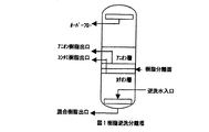
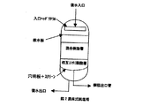
図1は、本発明に用いる樹脂逆洗分離塔の一例を示す概略構成図であり、図2は、本発明の復水脱塩装置の一例を示す混床式脱塩塔の概略構成図である。
(1)脱塩装置から樹脂逆洗分離塔に移送したイオン交換樹脂を、4m/h〜15m/h程度の線流速により、15分〜30分程度逆洗してアニオン樹脂、カチオン樹脂の2層に分離する。
(2)分離面上、約全層高の10〜20%程度を残して、アニオン樹脂をアニオン樹脂再生塔に移送する。
(3)次いで樹脂分離面の上下、約全層高の10〜20%の相互コンタミゾーンの樹脂を脱塩装置に返送する。
(4)ガウス分布を有するアニオン樹脂及びカチオン樹脂を逆洗分離することにより、分離面近傍に集中する互いに樹脂粒子の終末速度が重複或いは接近したイオン交換樹脂より構成される相互コンタミゾーンの樹脂の返送が完了したら、脱塩装置の水を一旦抜く。
(5)次いで、アニオン樹脂再生塔のアニオン樹脂を再生し、又は、そのままで樹脂逆洗分離塔に戻し、樹脂逆洗分離塔内の再生し、又は、そのままのカチオン樹脂と混合したのち、脱塩塔に返送する。
(6)脱塩塔への樹脂返送は、極力、樹脂の分離を防止するため、脱塩塔のドレンを行いながら実施する。
One example of specific conditions for carrying out the present invention will be described below.
FIG. 1 is a schematic configuration diagram showing an example of a resin backwash separation tower used in the present invention, and FIG. 2 is a schematic configuration diagram of a mixed bed type desalting tower showing an example of a condensate demineralization apparatus of the present invention. is there.
(1) The ion exchange resin transferred to the resin backwash separation tower from the desalting apparatus is backwashed for about 15 minutes to 30 minutes at a linear flow rate of about 4 m / h to 15 m / h, and anion resin and cation resin 2 Separate into layers.
(2) The anion resin is transferred to the anion resin regeneration tower, leaving about 10 to 20% of the total layer height on the separation surface.
(3) Next, 10 to 20% of the resin in the mutual contamination zone at the top and bottom of the resin separation surface and about the total layer height is returned to the desalting apparatus.
(4) By reverse-washing and separating an anionic resin and a cationic resin having a Gaussian distribution, the terminal particles of the resin in the mutual contamination zone composed of ion-exchange resins having terminal velocities overlapping or approaching each other concentrated in the vicinity of the separation surface. When the return is completed, drain the water from the desalinator.
(5) Next, the anion resin in the anion resin regeneration tower is regenerated or returned to the resin backwash separation tower as it is, regenerated in the resin backwash separation tower, or mixed with the cationic resin as it is and then removed. Return to the salt tower.
(6) Resin return to the desalting tower is performed while draining the desalting tower to prevent separation of the resin as much as possible.
(7)このような一連の操作によって、脱塩塔に以下のような特徴を有する混床が形成される。
(8)混床式脱塩塔の復水入口より導入された被処理水は、入口ヘッダラテラル散水板の整流機構を通過し、混合樹脂層を通り、次いで分離し難い相互コンタミ樹脂層を通り脱塩処理された後に、ウエッジワイヤスクリーンが取り付けられた穴明板を通過し、処理水として脱塩塔を出る。この脱塩処理において、被処理水中に含まれるイオン性不純物やアニオン樹脂及びカチオン樹脂自身から溶出する有機性不純物の除去が行われる。とりわけ、本発明の脱塩塔底部に分離し難い相互コンタミ樹脂層を配置させる技術は、従来の混床式脱塩塔において発生している、脱塩塔底部に集中するカチオン樹脂からの有機性不純物(ポリスチレンスルフォン酸)の処理水中への混入による原子炉水質の悪化事象を防止することが可能となり、運転方法の変更のみで原子炉水の高純度維持が容易に達成可能な優れた技術である。
(7) By such a series of operations, a mixed bed having the following characteristics is formed in the desalting tower.
(8) The treated water introduced from the condensate inlet of the mixed bed desalting tower passes through the rectifying mechanism of the inlet header lateral water spray plate, passes through the mixed resin layer, and then passes through the mutual contamination resin layer that is difficult to separate. After being desalted, it passes through a perforated plate fitted with a wedge wire screen and exits the desalting tower as treated water. In this desalting treatment, ionic impurities contained in the water to be treated and organic impurities eluted from the anion resin and the cation resin themselves are removed. In particular, the technology of arranging the mutual contamination resin layer that is difficult to separate at the bottom of the desalting tower of the present invention is an organic property from the cationic resin concentrated on the bottom of the desalting tower, which is generated in the conventional mixed bed desalting tower. This is an excellent technology that can prevent the deterioration of reactor water quality due to the mixing of impurities (polystyrene sulfonic acid) into the treated water, and can easily maintain the high purity of reactor water simply by changing the operation method. is there.
実施例1
ダウケミカル社製の強酸性陽イオン交換樹脂(HGR−W2H)及び強塩基性陰イオン交換樹脂(SPR−PC−OH)を水篩して、粒径分布を求めた。
求めた粒径分布を陽イオン交換樹脂を表1に、陰イオン交換樹脂を表2に示す。
A strongly acidic cation exchange resin (HGR-W2H) and a strongly basic anion exchange resin (SPR-PC-OH) manufactured by Dow Chemical Co. were screened with water to determine the particle size distribution.
The obtained particle size distribution is shown in Table 1 for the cation exchange resin and in Table 2 for the anion exchange resin.
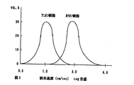
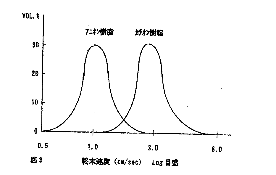
上記各イオン交換樹脂の粒径分布と真比重より終末速度の分布を求めると図3のようになる。
図3の摸式図に示すように、アニオン樹脂とカチオン樹脂の終末速度は、重なる部分が存在する。この部分は、通常の逆洗操作において、カチオン樹脂とアニオン樹脂の分離界面部分に相当し、樹脂は、互いに分離し難い状態になる。
この部分は、樹脂の種類やアニオン、カチオンの組合せにより相違するが、大よそ、樹脂分離面の樹脂層全層高の上下各10〜20%程度で、樹脂層高1000mmとすると上下各100mm〜200mm程度となる。
この部分の樹脂を選択的に抜出し、脱塩塔の樹脂層の最下部に充填することにより、分離し難い混床が形成される。
FIG. 3 shows the terminal velocity distribution obtained from the particle size distribution and true specific gravity of each ion exchange resin.
As shown in the schematic diagram of FIG. 3, the terminal velocity of the anion resin and the cation resin has an overlapping portion. This portion corresponds to a separation interface portion between the cation resin and the anion resin in a normal backwash operation, and the resins are difficult to separate from each other.
Although this part differs depending on the type of resin and the combination of anion and cation, it is about 10 to 20% above and below the total height of the resin layer on the resin separation surface. It becomes about 200 mm.
By selectively extracting the resin in this part and filling the lowermost part of the resin layer of the desalting tower, a mixed bed that is difficult to separate is formed.
実施例2
ダウケミカル社製の強酸性陽イオン交換樹脂(HGR−W2H)及び強塩基性陰イオン交拠樹脂(SPR−PC−OH)を組合わせて複混床を形成して通水試験を行い、処理水のイオン濃度の測定を行った。試験は、次の条件にて実施した。
内径30mmのカラムに、カチオン樹脂とアニオン樹脂それぞれ350mLを体積比で1/1にて充填する。全樹脂層高は1000mmとし、充填方法は次の通
りとした。
・ケース1=本発明の中間混合床として全体の20%相当量(層高として200mm)の混合樹脂を脱塩塔下部に配し、上層部には残りの混床を配した脱塩塔。
・ケース2:脱塩塔下部に層高として200mmの全体として20%相当量のカチオン樹脂リッチ層(カチオン樹脂/アニオン樹脂体積比=5/1)を配し、残りの樹脂を混床として上部に配した脱塩塔。
Example 2
A dough chemical strong acid cation exchange resin (HGR-W2H) and a strongly basic anion-replacement resin (SPR-PC-OH) are combined to form a mixed bed and conduct a water flow test. The water ion concentration was measured. The test was conducted under the following conditions.
A column having an inner diameter of 30 mm is packed with 350 mL of cationic resin and anionic resin at a volume ratio of 1/1. The total resin layer height was 1000 mm, and the filling method was as follows.
Case 1 = Desalting tower in which 20% of the total amount of mixed resin (200 mm as the layer height) is disposed in the lower part of the desalting tower and the remaining mixed bed is disposed in the upper part.
Case 2: A cation resin rich layer (cation resin / anion resin volume ratio = 5/1) equivalent to 20% of the total layer height of 200 mm is arranged at the bottom of the desalting tower, and the rest of the resin is mixed bed Desalting tower arranged in
・ケース3:脱塩塔下部に層高として200mmの全体として20%相当量のアニオン樹脂リッチ層(カチオン樹脂/アニオン樹脂体積比口1/5)を配し、残りの樹脂を混床として上部に配した脱塩塔。
従来技術:混床
通水線流速は実装置を模擬した120m/hとし、被処理水温度は45℃にて導電率が0.0055mS/mの超純水を通水した。処理水の一部を採取し、紫外線を照射して処理水中に含まれる有機化合物を分解して生成する無機イオン濃度を測定した。測定結果を表3に示す。
Case 3: An anion resin-rich layer (cation resin / anion resin volume ratio 1/5) equivalent to 20% of the total height of 200 mm is arranged at the bottom of the desalting tower, and the rest of the resin is mixed with the upper part Desalting tower arranged in
Prior art: Mixed bed The flow rate of the water line was 120 m / h simulating an actual apparatus, the temperature of the water to be treated was 45 ° C., and ultrapure water having a conductivity of 0.0055 mS / m was passed. A portion of the treated water was collected, and the concentration of inorganic ions generated by decomposing organic compounds contained in the treated water by irradiating with ultraviolet rays was measured. Table 3 shows the measurement results.
Claims (6)
Priority Applications (1)
| Application Number | Priority Date | Filing Date | Title |
|---|---|---|---|
| JP2004114299A JP4356987B2 (en) | 2004-04-08 | 2004-04-08 | Condensate demineralization treatment method and apparatus and method for forming packed bed thereof |
Applications Claiming Priority (1)
| Application Number | Priority Date | Filing Date | Title |
|---|---|---|---|
| JP2004114299A JP4356987B2 (en) | 2004-04-08 | 2004-04-08 | Condensate demineralization treatment method and apparatus and method for forming packed bed thereof |
Publications (2)
| Publication Number | Publication Date |
|---|---|
| JP2005296749A true JP2005296749A (en) | 2005-10-27 |
| JP4356987B2 JP4356987B2 (en) | 2009-11-04 |
Family
ID=35328947
Family Applications (1)
| Application Number | Title | Priority Date | Filing Date |
|---|---|---|---|
| JP2004114299A Expired - Fee Related JP4356987B2 (en) | 2004-04-08 | 2004-04-08 | Condensate demineralization treatment method and apparatus and method for forming packed bed thereof |
Country Status (1)
| Country | Link |
|---|---|
| JP (1) | JP4356987B2 (en) |
Cited By (2)
| Publication number | Priority date | Publication date | Assignee | Title |
|---|---|---|---|---|
| JP2009281875A (en) * | 2008-05-22 | 2009-12-03 | Ebara Corp | Method and device for condensate demineralization |
| CN112485169A (en) * | 2020-11-05 | 2021-03-12 | 西安热工研究院有限公司 | Method for improving resin identification effect in separation tower |
-
2004
- 2004-04-08 JP JP2004114299A patent/JP4356987B2/en not_active Expired - Fee Related
Cited By (3)
| Publication number | Priority date | Publication date | Assignee | Title |
|---|---|---|---|---|
| JP2009281875A (en) * | 2008-05-22 | 2009-12-03 | Ebara Corp | Method and device for condensate demineralization |
| US8861670B2 (en) | 2008-05-22 | 2014-10-14 | Ebara Corporation | Method and apparatus for condensate demineralization |
| CN112485169A (en) * | 2020-11-05 | 2021-03-12 | 西安热工研究院有限公司 | Method for improving resin identification effect in separation tower |
Also Published As
| Publication number | Publication date |
|---|---|
| JP4356987B2 (en) | 2009-11-04 |
Similar Documents
| Publication | Publication Date | Title |
|---|---|---|
| KR101918771B1 (en) | Ion-exchange device | |
| JP4943378B2 (en) | Condensate demineralization method and condensate demineralization apparatus | |
| KR20170137816A (en) | Regeneration of the pasty resin | |
| WO2011040278A1 (en) | Ion-exchange device, column therefor, and water treatment device | |
| JP3632331B2 (en) | Ion exchange method and ion exchange column used in this ion exchange method | |
| JP4869881B2 (en) | Ion exchange apparatus and ion exchange method | |
| JP2009281874A (en) | Method and device for condensate demineralization | |
| JP4931178B2 (en) | Condensate desalination method and apparatus | |
| JP4356987B2 (en) | Condensate demineralization treatment method and apparatus and method for forming packed bed thereof | |
| JP2940651B2 (en) | Pure water production equipment | |
| JP6337933B2 (en) | Water quality management system and operation method of water quality management system | |
| JP3913379B2 (en) | Regeneration method of mixed bed type ion exchange equipment | |
| JP2002361247A (en) | Pure water production method | |
| US3386914A (en) | Process of removing a component from a fluid | |
| JP5609181B2 (en) | Ion exchanger | |
| JPS595015B2 (en) | How to clean ion exchange resin | |
| RU2205692C2 (en) | Ion-exchange treatment method for organics-containing water involving countercurrent regeneration of ion-exchange materials | |
| JP4315385B2 (en) | Ion exchange tower | |
| JP4383091B2 (en) | Condensate desalination method and apparatus | |
| JP2742976B2 (en) | Mixed bed type ion exchange apparatus and method for producing pure water and ultrapure water using the mixed bed type ion exchange apparatus | |
| JP2654053B2 (en) | Condensate desalination equipment | |
| JPS6059013B2 (en) | How to regenerate mixed ion exchange resin | |
| JP2005296748A (en) | Condensate demineralizer and its regeneration method | |
| JP2742975B2 (en) | Regeneration method of ion exchange device | |
| JP2941121B2 (en) | Ultrapure water production equipment |
Legal Events
| Date | Code | Title | Description |
|---|---|---|---|
| A621 | Written request for application examination |
Free format text: JAPANESE INTERMEDIATE CODE: A621 Effective date: 20070305 |
|
| A977 | Report on retrieval |
Free format text: JAPANESE INTERMEDIATE CODE: A971007 Effective date: 20090521 |
|
| A131 | Notification of reasons for refusal |
Free format text: JAPANESE INTERMEDIATE CODE: A131 Effective date: 20090525 |
|
| A521 | Written amendment |
Free format text: JAPANESE INTERMEDIATE CODE: A523 Effective date: 20090706 |
|
| TRDD | Decision of grant or rejection written | ||
| A01 | Written decision to grant a patent or to grant a registration (utility model) |
Free format text: JAPANESE INTERMEDIATE CODE: A01 Effective date: 20090803 |
|
| A01 | Written decision to grant a patent or to grant a registration (utility model) |
Free format text: JAPANESE INTERMEDIATE CODE: A01 |
|
| A61 | First payment of annual fees (during grant procedure) |
Free format text: JAPANESE INTERMEDIATE CODE: A61 Effective date: 20090803 |
|
| FPAY | Renewal fee payment (event date is renewal date of database) |
Free format text: PAYMENT UNTIL: 20120814 Year of fee payment: 3 |
|
| R150 | Certificate of patent or registration of utility model |
Free format text: JAPANESE INTERMEDIATE CODE: R150 |
|
| FPAY | Renewal fee payment (event date is renewal date of database) |
Free format text: PAYMENT UNTIL: 20120814 Year of fee payment: 3 |
|
| FPAY | Renewal fee payment (event date is renewal date of database) |
Free format text: PAYMENT UNTIL: 20130814 Year of fee payment: 4 |
|
| R250 | Receipt of annual fees |
Free format text: JAPANESE INTERMEDIATE CODE: R250 |
|
| R250 | Receipt of annual fees |
Free format text: JAPANESE INTERMEDIATE CODE: R250 |
|
| R250 | Receipt of annual fees |
Free format text: JAPANESE INTERMEDIATE CODE: R250 |
|
| R250 | Receipt of annual fees |
Free format text: JAPANESE INTERMEDIATE CODE: R250 |
|
| R250 | Receipt of annual fees |
Free format text: JAPANESE INTERMEDIATE CODE: R250 |
|
| LAPS | Cancellation because of no payment of annual fees |