JP2005296748A - Condensate demineralizer and its regeneration method - Google Patents
Condensate demineralizer and its regeneration method Download PDFInfo
- Publication number
- JP2005296748A JP2005296748A JP2004114298A JP2004114298A JP2005296748A JP 2005296748 A JP2005296748 A JP 2005296748A JP 2004114298 A JP2004114298 A JP 2004114298A JP 2004114298 A JP2004114298 A JP 2004114298A JP 2005296748 A JP2005296748 A JP 2005296748A
- Authority
- JP
- Japan
- Prior art keywords
- resin
- cation
- layer
- condensate
- regeneration
- Prior art date
- Legal status (The legal status is an assumption and is not a legal conclusion. Google has not performed a legal analysis and makes no representation as to the accuracy of the status listed.)
- Ceased
Links
- 238000011069 regeneration method Methods 0.000 title claims abstract description 73
- 239000011347 resin Substances 0.000 claims abstract description 266
- 229920005989 resin Polymers 0.000 claims abstract description 266
- 150000001768 cations Chemical class 0.000 claims abstract description 77
- 230000008929 regeneration Effects 0.000 claims abstract description 64
- XLYOFNOQVPJJNP-UHFFFAOYSA-N water Substances O XLYOFNOQVPJJNP-UHFFFAOYSA-N 0.000 claims abstract description 56
- 150000001450 anions Chemical class 0.000 claims abstract description 50
- 238000000926 separation method Methods 0.000 claims abstract description 21
- 230000002378 acidificating effect Effects 0.000 claims abstract description 19
- 239000003456 ion exchange resin Substances 0.000 claims abstract description 18
- 229920003303 ion-exchange polymer Polymers 0.000 claims abstract description 18
- NWUYHJFMYQTDRP-UHFFFAOYSA-N 1,2-bis(ethenyl)benzene;1-ethenyl-2-ethylbenzene;styrene Chemical compound C=CC1=CC=CC=C1.CCC1=CC=CC=C1C=C.C=CC1=CC=CC=C1C=C NWUYHJFMYQTDRP-UHFFFAOYSA-N 0.000 claims abstract description 15
- 238000000605 extraction Methods 0.000 claims abstract description 10
- 238000000034 method Methods 0.000 claims description 24
- 239000003814 drug Substances 0.000 claims description 21
- 125000002091 cationic group Chemical group 0.000 claims description 13
- 230000001172 regenerating effect Effects 0.000 claims description 12
- 238000005115 demineralization Methods 0.000 claims description 9
- 230000002328 demineralizing effect Effects 0.000 claims description 9
- 238000011001 backwashing Methods 0.000 claims description 8
- 239000002253 acid Substances 0.000 claims description 7
- 239000000126 substance Substances 0.000 claims description 7
- 125000000129 anionic group Chemical group 0.000 claims description 4
- 238000010612 desalination reaction Methods 0.000 claims description 4
- QGZKDVFQNNGYKY-UHFFFAOYSA-N Ammonia Chemical compound N QGZKDVFQNNGYKY-UHFFFAOYSA-N 0.000 abstract description 24
- 229910021529 ammonia Inorganic materials 0.000 abstract description 12
- 230000006866 deterioration Effects 0.000 abstract description 4
- 238000011033 desalting Methods 0.000 description 13
- 229940079593 drug Drugs 0.000 description 11
- 239000012535 impurity Substances 0.000 description 9
- 150000002500 ions Chemical class 0.000 description 6
- 238000012360 testing method Methods 0.000 description 6
- OAKJQQAXSVQMHS-UHFFFAOYSA-N Hydrazine Chemical compound NN OAKJQQAXSVQMHS-UHFFFAOYSA-N 0.000 description 4
- FAPWRFPIFSIZLT-UHFFFAOYSA-M Sodium chloride Chemical compound [Na+].[Cl-] FAPWRFPIFSIZLT-UHFFFAOYSA-M 0.000 description 4
- QAOWNCQODCNURD-UHFFFAOYSA-N Sulfuric acid Chemical compound OS(O)(=O)=O QAOWNCQODCNURD-UHFFFAOYSA-N 0.000 description 4
- 238000010586 diagram Methods 0.000 description 4
- -1 steam Substances 0.000 description 4
- HEMHJVSKTPXQMS-UHFFFAOYSA-M Sodium hydroxide Chemical compound [OH-].[Na+] HEMHJVSKTPXQMS-UHFFFAOYSA-M 0.000 description 3
- 238000011161 development Methods 0.000 description 3
- 230000018109 developmental process Effects 0.000 description 3
- 238000009826 distribution Methods 0.000 description 3
- 230000000694 effects Effects 0.000 description 3
- 239000007788 liquid Substances 0.000 description 3
- 239000002245 particle Substances 0.000 description 3
- VEXZGXHMUGYJMC-UHFFFAOYSA-N Hydrochloric acid Chemical compound Cl VEXZGXHMUGYJMC-UHFFFAOYSA-N 0.000 description 2
- UQSXHKLRYXJYBZ-UHFFFAOYSA-N Iron oxide Chemical compound [Fe]=O UQSXHKLRYXJYBZ-UHFFFAOYSA-N 0.000 description 2
- QAOWNCQODCNURD-UHFFFAOYSA-L Sulfate Chemical compound [O-]S([O-])(=O)=O QAOWNCQODCNURD-UHFFFAOYSA-L 0.000 description 2
- 238000006243 chemical reaction Methods 0.000 description 2
- 239000002894 chemical waste Substances 0.000 description 2
- 239000000498 cooling water Substances 0.000 description 2
- 238000004132 cross linking Methods 0.000 description 2
- 238000012377 drug delivery Methods 0.000 description 2
- 238000010828 elution Methods 0.000 description 2
- 238000011049 filling Methods 0.000 description 2
- 239000012492 regenerant Substances 0.000 description 2
- 238000005070 sampling Methods 0.000 description 2
- 238000005201 scrubbing Methods 0.000 description 2
- 239000011780 sodium chloride Substances 0.000 description 2
- 229910001415 sodium ion Inorganic materials 0.000 description 2
- 238000012546 transfer Methods 0.000 description 2
- 239000012498 ultrapure water Substances 0.000 description 2
- 229910002651 NO3 Inorganic materials 0.000 description 1
- 230000032683 aging Effects 0.000 description 1
- 239000003513 alkali Substances 0.000 description 1
- 239000003795 chemical substances by application Substances 0.000 description 1
- 238000004140 cleaning Methods 0.000 description 1
- 230000007797 corrosion Effects 0.000 description 1
- 238000005260 corrosion Methods 0.000 description 1
- 238000005336 cracking Methods 0.000 description 1
- 238000000354 decomposition reaction Methods 0.000 description 1
- 230000003247 decreasing effect Effects 0.000 description 1
- 235000013399 edible fruits Nutrition 0.000 description 1
- 125000000524 functional group Chemical group 0.000 description 1
- 229910052739 hydrogen Inorganic materials 0.000 description 1
- 239000001257 hydrogen Substances 0.000 description 1
- 238000005342 ion exchange Methods 0.000 description 1
- 230000001678 irradiating effect Effects 0.000 description 1
- 239000011159 matrix material Substances 0.000 description 1
- 238000005259 measurement Methods 0.000 description 1
- 239000000203 mixture Substances 0.000 description 1
- 238000010525 oxidative degradation reaction Methods 0.000 description 1
- 238000005192 partition Methods 0.000 description 1
- 238000000746 purification Methods 0.000 description 1
- 150000003839 salts Chemical class 0.000 description 1
- 239000013535 sea water Substances 0.000 description 1
- 235000011121 sodium hydroxide Nutrition 0.000 description 1
- 238000001179 sorption measurement Methods 0.000 description 1
- 238000003756 stirring Methods 0.000 description 1
- 125000001174 sulfone group Chemical group 0.000 description 1
- 231100000331 toxic Toxicity 0.000 description 1
- 230000002588 toxic effect Effects 0.000 description 1
- 238000005406 washing Methods 0.000 description 1
- 239000002699 waste material Substances 0.000 description 1
Images

Landscapes
- Treatment Of Water By Ion Exchange (AREA)
Abstract
Description
本発明は、復水脱塩装置に係り、特に、汽力発電プラントに使用する復水脱塩装置とその再生方法に関する。 The present invention relates to a condensate demineralizer, and more particularly to a condensate demineralizer used in a steam power plant and a method for regenerating the same.
PWRプラントの二次冷却水系に設置されている復水脱塩装置は、復水中のイオン性不純物(Na、Cl、SO4など)を脱塩処理し、給水系から蒸気発生器に持ち込まれるイオン性不純物を極低レベルに低減し、蒸気発生器の伝熱管部において、イオン性不純物の濃縮により発生する恐れのある応カ腐食割れの防止を図っている。また、PWRプラントの二次冷却水系では、蒸気発生器へのクラッド(鉄酸化物)の持ち込みを抑制するため、復水中にアンモニアやヒドラジンなどを添加し、pHをアルカリ側にコントロールするAVT処理を行っている。 PWR plant secondary cooling water condensate demineralizer installed in the ionic impurities condensate water (Na, Cl, etc. SO 4) was desalted, ions brought into the steam generator from the water supply system In order to prevent corrosion cracking that may occur due to the concentration of ionic impurities in the heat transfer tube section of the steam generator. In addition, in the secondary cooling water system of the PWR plant, in order to suppress the introduction of clad (iron oxide) to the steam generator, AVT treatment is performed in which ammonia or hydrazine is added to the condensate to control the pH to the alkali side. Is going.
このためPWRプラントに用いる復水脱塩装置では、高純度の水質を確保するため、H型強酸性カチオン樹脂及びOH型強塩基性アニオイン樹脂の混床式脱塩器による運用を行っているが、復水中に添加されるアンモニアやヒドラジンなどがカチオン樹脂の大きな負荷となり、カチオン樹脂のイオンブレークが早まるため頻繁な通薬再生が必要となる。このため、PWRプラントでは、イオン交換樹脂の交換頻度の増加、再生剤、純水、蒸気、空気等の大量消費、及び処理する必要のある化学廃液の増加などの経済的問題、並びに運転員の負荷増大など、解決する必要のある幾つかの問題を抱えている。更に、強酸性カチオン樹脂より溶出する有機性不純物はカチオン樹脂の官能基であるスルホン基を有しており、分解すると硫酸イオンとなるため、処理水質低下原因の1つとなっている。 For this reason, in the condensate demineralizer used in the PWR plant, in order to ensure high-purity water quality, the H-type strongly acidic cation resin and the OH-type strongly basic anionine resin are operated using a mixed bed type desalter. Ammonia and hydrazine added to the condensate cause a heavy load on the cation resin, and the ion break of the cation resin is accelerated, so frequent drug regeneration is required. For this reason, in the PWR plant, economic problems such as an increase in the exchange frequency of ion exchange resins, a large consumption of regenerants, pure water, steam, air, etc., and an increase in chemical waste liquids that need to be treated, It has some problems that need to be solved, such as increased load. Furthermore, the organic impurities eluted from the strongly acidic cation resin have a sulfone group that is a functional group of the cation resin and, when decomposed, become sulfate ions.
この問題を解決する手段として、通薬再生の低減が可能な復水脱塩装置のアンモニア運用が考えられるが、従来のアンモニア運用はH、OH運用と比べて処理水質が悪化するため、そのままPWRプラントには適用できない。
アンモニア運用で処理水質の向上を図るためには、再生剤による逆再生率(Na型カチオン樹脂含率、Cl型アニオン樹脂含率)を従来のPWRレベルより2桁以上低減する必要がある。従来の混床式脱塩装置の樹脂分離技術では、理想的な分離操作を行っても、現状の逆再生率を1桁程度低減するのが限界である。
逆再生率を低減する方法としては、特開平8−117615号公報のように中間樹脂を使用する方法や、特開昭55−94650号公報のように樹脂分離に苛性ソーダを使用する方法、特開平4−100587号公報のように樹脂移送方法を工夫する方法、などが提唱されているが、理想的な分離操作を行っても、現状の逆再生率を1桁程度低減するのが限界である。
As a means to solve this problem, ammonia operation of a condensate demineralizer capable of reducing drug regeneration can be considered. However, since conventional ammonia operation deteriorates the quality of treated water as compared to H and OH operation, PWR is used as it is. Not applicable to plants.
In order to improve the quality of treated water by using ammonia, it is necessary to reduce the reverse regeneration rate (Na-type cation resin content, Cl-type anion resin content) by a regenerant by two orders of magnitude or more from the conventional PWR level. In the conventional resin separation technology of the mixed bed type desalination apparatus, even if an ideal separation operation is performed, the current reverse regeneration rate is limited to about one digit.
As a method for reducing the reverse regeneration rate, a method using an intermediate resin as disclosed in JP-A-8-117615, a method using caustic soda for resin separation as disclosed in JP-A-55-94650, Although a method of devising a resin transfer method as proposed in Japanese Patent Application Laid-Open No. 4-100587 has been proposed, even if an ideal separation operation is performed, it is a limit to reduce the current reverse regeneration rate by about one digit. .
カチオン樹脂とアニオン樹脂を混床にて使用する限り、逆再生率を大幅に低減することは困難である。
また、カチオン樹脂からの溶出物を低減する方法としては、特開平11−352283号公報にあるような、架橋度が通常使用されている8〜10%より高い12〜16%の強酸性ゲル型カテオン樹脂を適用する方法や、特開2001−314855号公報にあるようなアニオン樹脂を樹脂層下層部に配してカチオン樹脂から溶出するTOCを吸着する方法、特開平8−224579号公報にあるような強酸性ゲル型カチオン樹脂と粒径分布がガウス分布のポーラス型アニオン樹脂にて混床を形成する方法、などが提案されている。
しかし、架橋度の高い強酸性ゲル型カチオン樹脂を使用しても長期間の使用により酸化劣化が進行して有機性不純物の溶出は徐々に増加するため水質の低下は避けられない。また、アニオン樹脂を樹脂層下層部に配する方法ではカチオン樹脂から溶出する有磯性不純物の溶出は低減できるが、逆にアニオン樹脂より溶出する有機性不純物がリークして分解により硝酸イオンなどが生成するため、やはり水質低下を引き起こす。
As long as the cation resin and the anion resin are used in a mixed bed, it is difficult to significantly reduce the reverse regeneration rate.
Moreover, as a method of reducing the eluate from a cation resin, there exists 12-16% of strongly acidic gel type | molds higher than 8-10% in which the crosslinking degree is normally used like Unexamined-Japanese-Patent No. 11-352283. A method of applying a cateion resin, a method of disposing an anion resin in the lower layer portion of the resin layer as in JP-A-2001-314855, and adsorbing TOC eluted from the cation resin, disclosed in JP-A-8-224579 A method of forming a mixed bed using such a strongly acidic gel type cation resin and a porous type anion resin having a Gaussian particle size distribution has been proposed.
However, even if a strongly acidic gel-type cation resin having a high degree of crosslinking is used, the deterioration of water quality is unavoidable because oxidative degradation progresses over a long period of time and elution of organic impurities gradually increases. In addition, the method in which the anion resin is disposed in the lower layer part of the resin layer can reduce the elution of toxic impurities eluted from the cation resin, but conversely, the organic impurities eluted from the anion resin leak and the nitrate ions and the like are decomposed by the decomposition. As a result, water quality is lowered.
また、ポーラス型アニオン樹脂の使用は、該樹脂がマクロポアを有するため有機性不純物の吸着能力は高いが、原子力発電プラントの復水脱塩装置で通常使用されている市販のポーラス型アニオン樹脂は、粒径分布が420〜1180μmに分布するいわゆるガウス分布で平均粒径が800μm程度であることと、ポーラス型イオン交換樹脂がマクロポアを有するがために、樹脂マトリックスの部分は非常に緻密な構造を有しており、反応速度の面でゲル型樹脂に劣ることとなり、水質向上は期待できない。
本発明は、前述した事情に鑑みてなされたものであり、復水脱塩装置の運用をH、OH運用から、通薬再生頻度の低減が可能なアンモニア運用とすると共に、アンモニア運用時の水質悪化を抑制し、H、OH運用と同等の水質レベルを確保するため、樹脂再生時の逆再生率を現状より大幅に低減し、アンモニア運用時の処理水質の向上を図ることができる復水脱塩装置とその再生方法を提供することを課題とする。 The present invention has been made in view of the above-mentioned circumstances, and the operation of the condensate demineralization apparatus is changed from H and OH operation to ammonia operation capable of reducing the frequency of drug regeneration, and the water quality at the time of ammonia operation. In order to prevent deterioration and to ensure the same water quality level as H and OH operation, the reverse regeneration rate during resin regeneration can be greatly reduced compared to the current situation, and condensate drainage can be achieved to improve the treated water quality during ammonia operation. It is an object of the present invention to provide a salt device and a regeneration method thereof.
上記課題を解決するために本発明では、内部にイオン交換樹脂を充填した復水脱塩装置において、該充填したイオン交換樹脂が、アニオン樹脂層とカチオン樹脂層を交互に3層以上組合せた複床からなり、それらの各樹脂層は、相互に混じり合わないように分離壁で区分されていることを特徴とする復水脱塩装置としたものである。
前記復水脱塩装置において、樹脂層を組合せた複床は、最下層を弱酸性カチオン樹脂とすることができる。
また、前記復水脱塩装置において、該装置の上部に復水流入口を、下部に復水流出口を有し、前記分離壁で区分された樹脂層の各々の下部には、該樹脂層の樹脂を抜出す抜出管が、また、樹脂層の各々の上部には樹脂を返送する返送管が配備されると共に、該抜出管及び返送管がそれぞれの樹脂の再生塔に接続されていることとした。
In order to solve the above problems, in the present invention, in a condensate demineralization apparatus filled with an ion exchange resin, the filled ion exchange resin has a combination of three or more anion resin layers and cation resin layers alternately. The condensate demineralizer is composed of a floor, and each of these resin layers is divided by a separation wall so as not to mix with each other.
In the condensate demineralization apparatus, the lowermost layer of the double bed combined with the resin layer may be a weakly acidic cation resin.
Further, in the condensate demineralization apparatus, a condensate inlet is provided at an upper part of the apparatus, a condensate outlet is provided at a lower part, and a resin of the resin layer is provided at a lower part of each of the resin layers separated by the separation wall. And a return pipe for returning the resin to each upper part of the resin layer, and the extraction pipe and the return pipe are connected to the respective resin regeneration towers. It was.
また、本発明では、前記復水脱塩装置の再生方法において、薬品再生が必要になったイオン交換樹脂は、分離壁で区分されたそれぞれの樹脂層に設置されている樹脂抜出管により、水及び/又は空気によりカチオン樹脂はカチオン樹脂再生塔に、また、アニオン樹脂はアニオン樹脂再生塔に直接移送され、それぞれ通薬再生されて洗浄された後、直接、水及び/又は空気により前記抜出された分離壁で区分された樹脂層に返送されることを特徴とする復水脱塩装置の再生方法としたものである。
前記復水脱塩装置の再生方法において、前記カチオン樹脂再生塔では、前記樹脂層の最下層が弱酸性カチオン樹脂の場合、該弱酸性カチオン樹脂を該再生塔の分離壁により区分された下部隔室に移送し、上部隔室のカチオン樹脂の上部から下方流で通薬再生することができる。
Further, in the present invention, in the regeneration method of the condensate demineralizer, the ion exchange resin that requires chemical regeneration is provided by a resin extraction pipe installed in each resin layer separated by a separation wall, The cation resin is transferred directly to the cation resin regeneration tower by water and / or air, and the anion resin is directly transferred to the anion resin regeneration tower, regenerated and washed, respectively, and then directly removed by water and / or air. The method is a method for regenerating a condensate demineralizer characterized by being returned to the resin layer separated by the separated separation wall.
In the regeneration method of the condensate demineralizer, in the cation resin regeneration tower, when the lowermost layer of the resin layer is a weak acid cation resin, the weak acid cation resin is separated by a lower partition separated by a separation wall of the regeneration tower. It can be transferred to the chamber and can be regenerated by downward flow from the top of the cation resin in the upper compartment.
前記復水脱塩装置の再生方法において、前記カチオン樹脂再生塔においては、該樹脂層から移送されるカチオン樹脂に余剰カチオン樹脂を加え、逆洗して破砕樹脂及び/又は微細樹脂をオーバーフロー除去すると共に、樹脂層上部の樹脂を余剰カチオン樹脂タンクに抜取った後に通薬再生し、また、アニオン樹脂再生塔においては、該樹脂層から移送されるアニオン樹脂に余剰アニオン樹脂を加え、逆洗して破砕樹脂及び/又は微細樹脂をオーバーフロー除去すると共に、樹脂層下部よりカウンターフロー水を入れながら、上層のアニオン樹脂のみを通薬再生することができる。
また、前記再生方法において、前記樹脂層から樹脂再生塔に移送されるカチオン樹脂及び/又はアニオン樹脂を、破砕樹脂及び/又は微細樹脂のみが通過する分離装置により分離した後にそれぞれの樹脂再生塔に移送することができる。
In the regeneration method of the condensate demineralizer, in the cation resin regeneration tower, an excess cation resin is added to the cation resin transferred from the resin layer, and backwashing is performed to remove the crushed resin and / or fine resin by overflow. In addition, after the resin at the top of the resin layer is taken out into the surplus cation resin tank, the medicine is regenerated, and in the anion resin regeneration tower, the surplus anion resin is added to the anion resin transferred from the resin layer and backwashed. Thus, the crushing resin and / or the fine resin can be removed by overflow, and only the anionic resin in the upper layer can be regenerated by feeding counterflow water from the bottom of the resin layer.
Further, in the regeneration method, after the cation resin and / or the anion resin transferred from the resin layer to the resin regeneration tower are separated by a separation device through which only the crushed resin and / or fine resin passes, Can be transported.
以上、詳細に説明したように本発明によれば、下記のような優れた効果が期待される。
(1)本発明は、混床式復水脱塩装置の最大の課題である逆再生を基本的に生じさせない技術であると共に、複数段の樹脂層の組合せにより構成される複床を使用することにより、混床と同等の高純度水質を確保することが可能であり、アンモニア運用時の処理水質をH、OH型イオン交換樹脂による運用と同レベルまで向上させる技術である。本発明により、現在のPWR二次系復水脱塩装置のH、OH型イオン交換樹脂による運用の問題点である頻繁な再生による再生剤、純水、空気等の大量消費、化学廃液の増加、並びに運転員の負荷増大などを解消することができる画期的技術であり、その経済効果は絶大である。
As described above in detail, according to the present invention, the following excellent effects are expected.
(1) The present invention is a technique that basically does not cause reverse regeneration, which is the greatest problem of a mixed-bed condensate demineralization apparatus, and uses a multiple bed composed of a combination of a plurality of resin layers. By this, it is possible to ensure a high-purity water quality equivalent to that of a mixed bed, and it is a technology that improves the quality of treated water during ammonia operation to the same level as the operation using H and OH type ion exchange resins. According to the present invention, a large amount of regenerant, pure water, air, etc. are consumed due to frequent regeneration, which is a problem in the operation of the current PWR secondary condensate demineralizer using H and OH type ion exchange resins, and chemical waste liquid is increased. In addition, it is an epoch-making technology that can eliminate an increase in the load on the operator, and its economic effect is enormous.
(2)本発明は混床式復水脱塩装置の最大の課題である逆再生を基本的に生じさせない技術であると共に、破砕樹脂及び微細樹脂を除去することが可能であるため、BWRプラントの原子炉水の高純度化にも幅広く適用できる技術であり、近年のプラント高経年化対策への適用など、その波及効果は絶大である。
(3)通薬再生頻度を大幅に低減できる。従来の技術では、各脱塩器に対して10日に1回程度通薬再生を実施している。これは、逆再生によりカチオン樹脂に負荷したNaイオンが、系統内に注入しているアンモニアの吸着により樹脂下層側に押し出されることによる処理水質の低下を抑止するために、Naイオンが下流側にリークする前に通薬再生を行う必要があるためである。
逆再生率を大幅に低減できれば、この事象による通薬再生は不要となり、薬品代や運転員負荷など、O&Mコストを大幅に低減することができる。通薬再生頻度は復水器での海水漏洩の発生の有無など被処理水質に依存するが、通常、通薬再生は3ヵ月に1回程度実施すればよいこととなる。
(2) The present invention is a technology that does not basically cause reverse regeneration, which is the biggest problem of the mixed-bed condensate demineralizer, and it is possible to remove crushed resin and fine resin. This technology can be widely applied to increase the purity of nuclear reactor water, and its ripple effects are enormous, including application to recent plant aging countermeasures.
(3) Drug delivery frequency can be greatly reduced. In the conventional technology, medicine regeneration is performed about once every 10 days for each desalter. This is because Na ions loaded on the cation resin due to reverse regeneration are pushed down to the resin lower layer side due to adsorption of ammonia injected into the system, so that Na ions are moved downstream. It is because it is necessary to perform medicine regeneration before leaking.
If the reverse regeneration rate can be drastically reduced, drug regeneration due to this event becomes unnecessary, and O & M costs such as chemical costs and operator load can be greatly reduced. The frequency of drug regeneration depends on the quality of the water to be treated, such as the presence or absence of seawater leaks in the condenser, but normally, drug regeneration should be performed about once every three months.
(4)また、複床式脱塩装置の場合、カチオン樹脂とアニオン樹脂のイオン交換反応が同時に起きないため、通薬再生後のリンス特性が低下すると一般的に言われている。これは、水素イオンと水酸イオンが同時発生すれば、溶解度積が非常に小さいことから速やかに水となるため、リンスが効率的に行われるためであるといわれている。複床式の場合、これが同時におきないため、リンス特性上、不利であるといわれている。しかし、本発明では、通薬再生頻度を前述の通り大幅に低減できるため、リンスに時間をかけることが可能である。従来技術では、10日毎に通薬再生を実施するには、1つの脱塩塔の再生にかけられる時間は2日程度であり、リンスに十分な時間をかけることができない。しかし、本発明では、その9倍の時間がかけられるため、時間をかけてリンスを行うことで対応が可能である。脱塩塔で採水する前には、再循環操作が行われてる。これは、被処理水を通水し処理水を復水脱塩装置の入口側に戻す操作であり、これにより、通薬再生時の残留薬品が下流側にリークしないようにするものである。著しく劣化が進行したイオン交換樹脂でも、通常では1時間程度のところを、24時間程度の再循環運転を実施することで問題ないことが確認されている。従って、通薬再生頻度を著しく低減可能な本発明では、リンスに十分な時間がかけられるため、リンス特性の問題は発生しない。 (4) In addition, in the case of a multiple bed desalting apparatus, it is generally said that the rinsing characteristics after the regeneration of medicine are deteriorated because the ion exchange reaction of the cation resin and the anion resin does not occur simultaneously. It is said that if hydrogen ions and hydroxide ions are generated at the same time, the solubility product is very small, so that the water is promptly converted into water, so that rinsing is performed efficiently. In the case of a multiple floor type, it is said that this does not occur at the same time, which is disadvantageous in terms of rinse characteristics. However, in the present invention, the frequency of drug regeneration can be greatly reduced as described above, and therefore it is possible to take time for rinsing. In the prior art, in order to perform drug regeneration every 10 days, the time required for regeneration of one desalting tower is about 2 days, and sufficient time cannot be taken for rinsing. However, in the present invention, since it takes nine times as long, it can be handled by rinsing over time. Before collecting water in the desalting tower, a recirculation operation is performed. This is an operation of passing the water to be treated and returning the treated water to the inlet side of the condensate demineralizer, thereby preventing residual chemicals from leaking to the downstream side during the regeneration. It has been confirmed that even an ion exchange resin that has undergone significant deterioration normally has no problem by performing a recirculation operation for about 24 hours in about 1 hour. Therefore, in the present invention capable of remarkably reducing the frequency of drug regeneration, a sufficient time is required for rinsing, so that the problem of rinsing characteristics does not occur.
本発明者は、種々検討を行った結果、復水を処理する脱塩塔において、アニオン樹脂、カチオン樹脂、夫々の単床を、被処理水の水質に応じ複数段、組み合わせて構成される複床式脱塩塔により脱塩処理を行う方法を見出したことにより、PWRプラントの使用条件において、混床式脱塩塔と同等の処理水質が確保できた。続いて、脱塩塔内の樹脂層は、スクリーン等を取り付けた分離壁により区分され、各層のイオン交換樹脂を採水終了後、夫々の樹脂層に設置されている樹脂抜出管より、直接、各々の再生塔に移送し通薬再生する方法により、混床式と違いカチオン樹脂とアニオン樹脂は、一切、混ざることはなく、分離操作を行わずに再生することが可能となり、これにより再生剤による逆再生が完全に排除できた。 As a result of various studies, the present inventor has found that in a demineralization tower for treating condensate, an anion resin, a cation resin, and a single bed of each are combined in multiple stages according to the quality of the water to be treated. As a result of finding a method for performing a desalting treatment using a floor-type desalting tower, it was possible to secure a treated water quality equivalent to that of the mixed-bed type desalting tower under the use conditions of the PWR plant. Subsequently, the resin layer in the desalting tower is divided by a separation wall to which a screen or the like is attached. After sampling the ion exchange resin of each layer, the resin layer is directly connected to the resin extraction pipe installed in each resin layer. In the method of transferring to each regeneration tower and regenerating the medicine, unlike the mixed bed type, the cation resin and the anion resin are not mixed at all, and can be regenerated without performing a separation operation. Reverse regeneration by the agent was completely eliminated.
更に、破砕樹脂及び/又は微細樹脂の各樹脂層への混入防止対策を見出したことにより、従来の逆再生率(Na逆再生率:0.05%、Cl逆再生率:1.0%)を大幅に下回る高純度の樹脂再生を可能にすることができ、アンモニア運用においても高純度の処理水が確保できた。また、樹脂層の最下層を弱酸性カチオン樹脂とすることにより、カチオン樹脂により溶出する有機性不純物由来の硫酸イオン濃度を低減することができた。
更に、カチオン樹脂を通薬再生する際、弱酸性樹脂の再生効率が高いことを利用し、カチオン樹脂再生塔において上部隔室に強酸性カチオン樹脂を、下部隔室に弱酸性カチオン樹脂を配し、下方流にて通薬再生することにより使用する薬品量を低減することが可能である。
Furthermore, by finding out measures for preventing the mixture of crushed resin and / or fine resin into each resin layer, conventional reverse regeneration rate (Na reverse regeneration rate: 0.05%, Cl reverse regeneration rate: 1.0%) It was possible to regenerate high-purity resin significantly lower than the above, and high-purity treated water could be secured even in ammonia operation. In addition, by using a weakly acidic cation resin as the lowermost layer of the resin layer, the concentration of sulfate ions derived from organic impurities eluted by the cation resin could be reduced.
Furthermore, when the cationic resin is regenerated through medicine, taking advantage of the high regeneration efficiency of the weak acidic resin, a strong acidic cationic resin is placed in the upper compartment and a weak acidic cationic resin is placed in the lower compartment in the cationic resin regeneration tower. It is possible to reduce the amount of chemicals used by regenerating the medicine in the downward flow.
以下に発明の詳細を記述する。
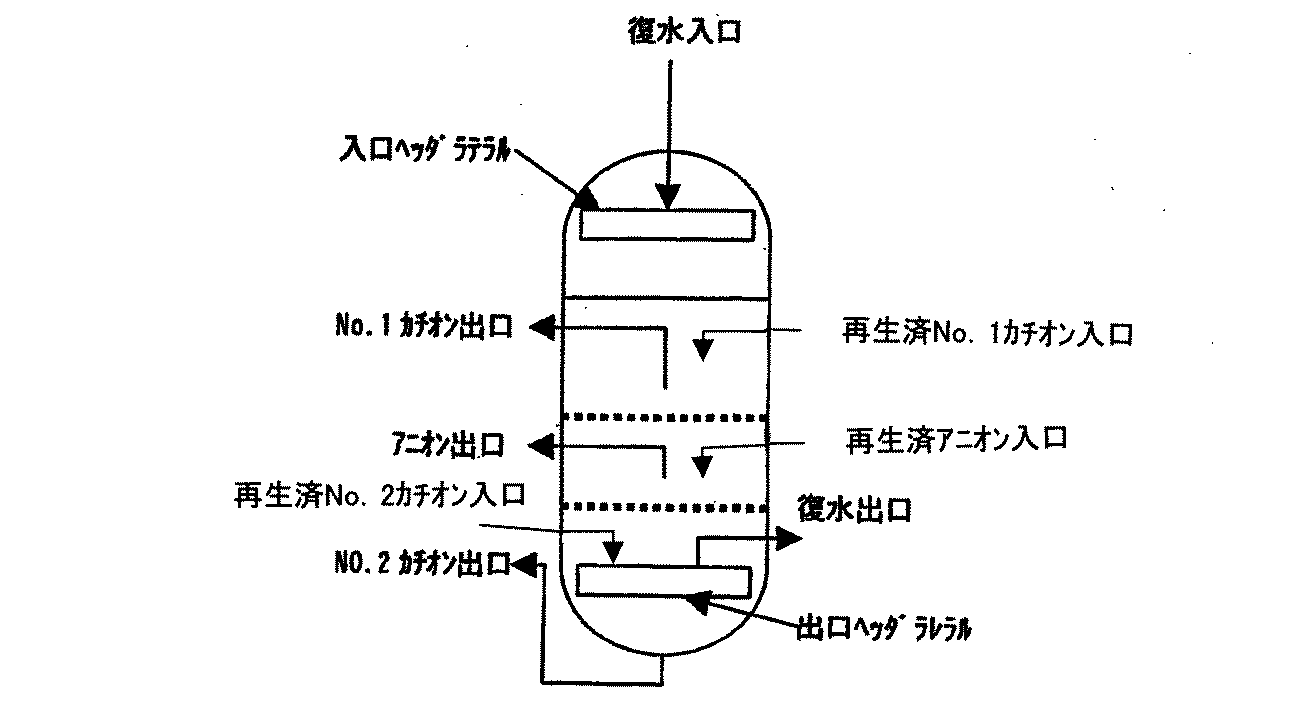
一例として、樹脂層上部よりカチオン樹脂、アニオン樹脂、カチオン樹脂の3層により構成した複床式脱塩装置の説明を行う。複床式脱塩装置は、図1のようにNo.1カチオン層、アニオン層、No.2カチオン層のように交互に組み合わせた複床により構成される。復水は、入口ヘッダラテラルを通り、No.1カチオン層、アニオン層、No.2カチオン層を交互に通過し脱塩処理された後、出口ヘッダラテラルにより集水され脱塩処理される。採水を終了した樹脂は、夫々の樹脂層に設置されている樹脂抜出管より、カチオン樹脂再生塔、アニオン樹脂再生塔に抜き出され再生される。各樹脂層は、穴明き板にウエッジワイヤースクリーンを取り付けた分離壁により区分され、各層のイオン交換樹脂は混ざらない構造になっている。各樹脂層の層高は、上部カチオン層:約600mm、アニオン層:約約600mm、下部カチオン層:約600mm程度を目安に決め、被処理の水質、処理流速により最適層高を調整するものとする。
なお、弱酸性カチオン樹脂を用いる場合は、No.2カチオン層が弱酸性カチオン樹脂層となる。
Details of the invention are described below.
As an example, a multi-bed desalination apparatus constituted by three layers of a cation resin, an anion resin, and a cation resin from the top of the resin layer will be described. As shown in FIG. 1 cation layer, anion layer, No. 1 It is composed of multiple beds that are combined alternately like two cation layers. Condensate passes through the inlet header lateral, 1 cation layer, anion layer, No. 1 After passing through two cation layers alternately and desalting, water is collected by the outlet header lateral and desalted. The resin from which water collection has been completed is extracted from the resin extraction pipes installed in the respective resin layers to the cation resin regeneration tower and the anion resin regeneration tower and regenerated. Each resin layer is divided by a separation wall in which a wedge wire screen is attached to a perforated plate, and the ion exchange resin of each layer is not mixed. The layer height of each resin layer is determined based on the upper cation layer: about 600 mm, the anion layer: about 600 mm, and the lower cation layer: about 600 mm, and the optimum layer height is adjusted according to the water quality to be treated and the treatment flow rate. To do.
In addition, when using weakly acidic cation resin, it is No. The two cation layers become weakly acidic cation resin layers.
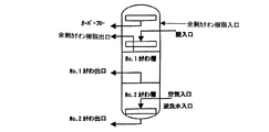
樹脂塔から抜き出されたカチオン樹脂は、直接カチオン樹脂再生塔に移送される。
図2のように、カチオン樹脂再生塔は、No.1カチオン樹脂とNo.2カチオン樹脂を同時に逆洗及び通薬再生するための内装管と、それぞれの樹脂を脱塩装置の樹脂層に移送するための樹脂抜き出し管より構成されている。脱塩装置の樹脂層から移送されるカチオン樹脂に余剰カチオン樹脂を加え、空気によるスクラビングの後に、展開率100%以上で30分以上逆洗して、破砕樹脂及び/又は微細樹脂をオーバーフロー除去する。本操作は、必要により複数回繰り返す。
逆流終了後、カチオン樹脂層に混入する可能性のある破砕樹脂及び/又は繊細樹脂を除去するため、カチオン樹脂の上層を余剰カチオン樹脂タンクに抜き出す。通薬を実施した樹脂は、十分にリンスを行った後にNo.1カチオン、No.2カチオンの順で脱塩装置の樹脂層に返送する。余剰カチオン樹脂は、余剰カチオン樹脂タンクに入れておき、適時サンプリング、分析し、破砕樹脂及び/又は微細樹脂の混入量が増加してきたならば新品樹脂と交換する。
なお、弱酸性カチオン樹脂を用いる場合は、通薬再生を別個に塩酸などの再生剤を用いて再生してもよい。
The cationic resin extracted from the resin tower is directly transferred to the cationic resin regeneration tower.
As shown in FIG. No. 1 cationic resin and No. 1 It is composed of an inner tube for backwashing and regenerating the two cation resins at the same time, and a resin extraction tube for transferring each resin to the resin layer of the demineralizer. Add surplus cation resin to the cation resin transferred from the resin layer of the desalting apparatus, and after scrubbing with air, backwash with a development rate of 100% or more for 30 minutes or more to remove the crushed resin and / or fine resin by overflow. . This operation is repeated several times as necessary.
After the backflow is completed, the upper layer of the cation resin is extracted into an excess cation resin tank in order to remove crushing resin and / or fine resin that may be mixed into the cation resin layer. The resin subjected to the drug passing was No. after thoroughly rinsing. 1 cation, no. It returns to the resin layer of a desalination apparatus in order of 2 cations. The surplus cation resin is placed in a surplus cation resin tank, sampled and analyzed in a timely manner, and replaced with a new resin if the amount of crushed resin and / or fine resin is increased.
In addition, when using a weakly acidic cation resin, you may reproduce | regenerate a medicine delivery separately using regenerants, such as hydrochloric acid.
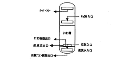
脱塩塔から抜き出されたアニオン樹脂は、直接アニオン樹脂再生塔に移送される。
図3のように、アニオン樹脂再生塔は、アニオン樹脂を逆洗及び通薬再生するための内装管と、アニオン樹脂を脱塩装置の樹脂層に移送するための樹脂抜出管より構成されている。
樹脂層から移送されるアニオン樹脂に余剰アニオン樹脂を加え、空気によるスクラビングの後に、展開率100%以上で30分以上逆洗して破砕樹脂及び/又は微細樹脂をオーバーフロー除去する。逆洗終了後、樹脂層下部に混在している可能性のあるカチオン樹脂の破砕樹脂及び/又は微細樹脂を逆再生させないため、塔下部の逆洗水入口よりカウンターブロー水を入れながら薬液流出口から排出し、上層のアニオン樹脂のみを通薬再生する。通薬を終了した樹脂は、十分にリンスを行った後に脱塩装置の樹脂層に返送する。底部の余剰アニオン樹脂は、常時アニオン樹脂再生塔に入れておき、適時サンプリング、分析し破砕樹脂及び/又は微細樹脂の混入量が増加してきたならば、余剰アニオン樹脂出口より抜き出し新品樹脂と交換する。
The anion resin extracted from the desalting tower is directly transferred to the anion resin regeneration tower.
As shown in FIG. 3, the anion resin regeneration tower is composed of an inner tube for backwashing and regenerating the anion resin and a resin extraction tube for transferring the anion resin to the resin layer of the desalting apparatus. Yes.
Excess anion resin is added to the anion resin transferred from the resin layer, and after scrubbing with air, the crushed resin and / or fine resin is removed by overflow by backwashing at a development rate of 100% or more for 30 minutes or more. After the backwashing is completed, the chemical solution outlet is installed with counter blow water from the backwashing water inlet at the bottom of the tower to prevent reverse regeneration of the crushing resin and / or fine resin of the cationic resin that may be mixed in the lower part of the resin layer. And only the anionic resin in the upper layer is regenerated. Resin that has completed the drug delivery is thoroughly rinsed and returned to the resin layer of the desalting apparatus. The excess anion resin at the bottom is always placed in the anion resin regeneration tower, and when sampling and analysis are performed in a timely manner and the amount of crushed resin and / or fine resin is increased, it is extracted from the outlet of the excess anion resin and replaced with a new resin. .
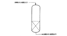
また、上述の復水脱塩装置において、分離壁のスクリーン等の目開きを通過する可能性のある破砕樹脂及び/又は微細樹脂を完全に除去するため、脱塩装置の樹脂層から移送されるカチオン樹脂及びアニオン樹脂を、破砕樹脂及び/又は微細樹脂のみが通過する目開きを有する振動ふるい装置などの分離装置により夫々、別個に分離して破砕樹脂及び/又は微細樹脂を除去した後に、通薬再生するプロセスを入れることも可能である。
さらに、前述の復水脱塩装置の再生方法において、樹脂層からの樹脂の取出し、一連の再生操作、脱塩塔への樹脂の戻し、など全て、又は一部の運転操作について、シーケンサー、又はプログラムタイマー等を使用することにより自動運転をするとも可能である。
Further, in the above-described condensate demineralizer, in order to completely remove crushed resin and / or fine resin that may pass through openings such as a screen of the separation wall, the demineralizer is transferred from the resin layer of the demineralizer. The cation resin and the anion resin are separated separately by a separating device such as a vibrating screen device having an opening through which only the crushed resin and / or fine resin passes, and then the crushed resin and / or fine resin is removed. It is also possible to include a process for drug regeneration.
Further, in the above-described regeneration method of the condensate demineralizer, a sequencer, or all of a part of operation operations such as taking out the resin from the resin layer, a series of regenerating operations, returning the resin to the desalting tower, etc. Automatic operation is possible by using a program timer or the like.
実施例1
原子力発電プラントの復水脱塩装置で広く使用されているイオン交換樹脂(ダウケミカル社製)である強酸性ゲル型カチオン樹脂MS650Cと、強塩基性1型ゲル型アニオン樹脂MS550Aとを組み合わせて、複床を形成して通水試験を行い、処理水の導電率及びイオン濃度の測定を行うと共に、H、OH型基準での破過時間の測定を行った。試験は、次の条件にて実施した。
内径30mmのカラムにカチオン樹脂とアニオン樹脂を体積比で2/1にて充填する。樹脂層高は850mmとし、充填方法は次の通りとした。
・ケース1:上部からカチオン樹脂(以下、C)/アニオン樹脂(以下、A)の2層
・ケース2:上部からC/A/Cの3層
・ケース3:上部からC/A/C/Aの4層
・ケース4:上部からC/A/C/A/Cの5層
従来技術:混床
Example 1
Combining strongly acidic gel type cation resin MS650C, which is an ion exchange resin (manufactured by Dow Chemical Co., Ltd.) widely used in condensate demineralization equipment of nuclear power plants, and strongly basic type 1 gel type anion resin MS550A, A double bed was formed and a water flow test was conducted to measure the conductivity and ion concentration of the treated water, and the breakthrough time was measured on the basis of H and OH types. The test was conducted under the following conditions.
A column having an inner diameter of 30 mm is packed with a cation resin and an anion resin at a volume ratio of 2/1. The resin layer height was 850 mm, and the filling method was as follows.
Case 1: Two layers of cation resin (hereinafter C) / anion resin (hereinafter A) from the top Case 2: Three layers of C / A / C from the top Case 3: C / A / C / from the top 4 layers of A ・ Case 4: 5 layers of C / A / C / A / C from the top Conventional technology: Mixed floor
通水線流速は、実装置を模擬した80m/hとし、被処理水温度は35℃、入口水質条件は次の通りとした。
・3.2mg/L as NH4
・0.2mg/L as N2H4
・4.0mg/L as NaCl
・0.5mg/L as Na2SO4
処理水の導電率及びイオン濃度の測定結果を表1に示す。
The water flow velocity was 80 m / h simulating an actual device, the temperature of the water to be treated was 35 ° C., and the inlet water quality conditions were as follows.
・ 3.2 mg / L as NH 4
0.2 mg / L as N 2 H 4
・ 4.0 mg / L as NaCl
・ 0.5 mg / L as Na 2 SO 4
Table 1 shows the measurement results of the conductivity and ion concentration of the treated water.
実施例2
原子力発電プラントの復水脱塩装置で広く使用されているイオン交換樹脂(ダウケミカル社製)である強酸性ゲル型カチオン樹脂MS650Cと、強塩基性1型ゲル型アニオン樹脂MS550Aとを用い、逆洗による破砕樹脂除去挙動を調査した試験は、次の条件にて実施した。
樹脂500mLを1Lビーカに入れ、純水を500mL添加し、マグネチックスターラにて30分間撹拌する。この樹脂を内径30mmのカラムに充填し、展開率が100%となるよう流量を調整し、逆洗廃液中に含まれる微細樹脂量を測定した。試験詰果を表3に示す。
Example 2
Using strongly acidic gel-type cation resin MS650C, which is an ion exchange resin (manufactured by Dow Chemical Co., Ltd.) widely used in condensate demineralizers of nuclear power plants, and strongly basic type 1 gel-type anion resin MS550A, the reverse The test which investigated the crushing resin removal behavior by washing | cleaning was implemented on the following conditions.
Add 500 mL of resin to a 1 L beaker, add 500 mL of pure water, and stir for 30 minutes with a magnetic stirrer. This resin was packed in a column having an inner diameter of 30 mm, the flow rate was adjusted so that the development rate was 100%, and the amount of fine resin contained in the backwash waste liquid was measured. The test fruit is shown in Table 3.
実施例3
原子力発電プラントの復水脱塩装置で広く使用されているイオン交換樹脂(ダウケミカル日本(株)製)である強酸性ゲル型カチオン樹脂MS650Cと、弱酸性カチオン樹脂MAC3、強塩基性1型ゲル型アニオン樹脂MS550Aを組み合わせて複床を形成して通水試験を行い、処理水の導電率及びイオン濃度の測定を行うと共に、H、OH型基準での破過時間の測定を行った。試験は、次の条件にて実施した。
内径30mmのカラムに、カチオン樹脂とアニオン樹脂を体積比で2/1にて充填する。樹脂層面は850mmとし、充填方法は次の通りとした。
・本発明:上部から強酸性カチオン樹脂/アニオン樹脂/弱酸性カチオン樹脂の3層
・従来技術:混床
Example 3
Strongly acidic gel type cationic resin MS650C, which is an ion exchange resin (manufactured by Dow Chemical Japan Co., Ltd.) widely used in condensate demineralizers of nuclear power plants, weakly acidic cationic resin MAC3, and strongly basic type 1 gel A double bed was formed by combining the type anion resin MS550A, a water passage test was performed, the conductivity and ion concentration of the treated water were measured, and the breakthrough time was measured on the basis of H and OH types. The test was conducted under the following conditions.
A column having an inner diameter of 30 mm is packed with cationic resin and anionic resin at a volume ratio of 2/1. The resin layer surface was 850 mm, and the filling method was as follows.
-The present invention: from the top three layers of strong acid cation resin / anion resin / weak acid cation resin-conventional technology: mixed bed
通水線流速は実装置を模擬した80m/hとし、被処理水温度は35℃、入口水質条件は次の通りとした。
・3.2mg/L as NH4
・0.2mg/L as N2H4
・4.0mg/L as NaCl
・0.5mg/L as Na2SO4
The water line flow velocity was 80 m / h simulating an actual apparatus, the water temperature to be treated was 35 ° C., and the inlet water quality conditions were as follows.
・ 3.2 mg / L as NH 4
0.2 mg / L as N 2 H 4
・ 4.0 mg / L as NaCl
・ 0.5 mg / L as Na 2 SO 4
処理水の導電率及びイオン濃度測定結果を表4に示す。
また、従来技術である混床樹脂のH、OH型基準での破過時間を1としたときの破過時間比を表5に示す。
また、処理水に紫外線を照射し、処理水中に含まれる有機性不純物を分解し生成する硫酸濃度の測定を行った。その結果を表6に示す。従来技術に比べ本発明の方が硫酸濃度は低く水質の高純度化に寄与することが確認された。
Claims (7)
Priority Applications (1)
| Application Number | Priority Date | Filing Date | Title |
|---|---|---|---|
| JP2004114298A JP2005296748A (en) | 2004-04-08 | 2004-04-08 | Condensate demineralizer and its regeneration method |
Applications Claiming Priority (1)
| Application Number | Priority Date | Filing Date | Title |
|---|---|---|---|
| JP2004114298A JP2005296748A (en) | 2004-04-08 | 2004-04-08 | Condensate demineralizer and its regeneration method |
Publications (1)
| Publication Number | Publication Date |
|---|---|
| JP2005296748A true JP2005296748A (en) | 2005-10-27 |
Family
ID=35328946
Family Applications (1)
| Application Number | Title | Priority Date | Filing Date |
|---|---|---|---|
| JP2004114298A Ceased JP2005296748A (en) | 2004-04-08 | 2004-04-08 | Condensate demineralizer and its regeneration method |
Country Status (1)
| Country | Link |
|---|---|
| JP (1) | JP2005296748A (en) |
Cited By (3)
| Publication number | Priority date | Publication date | Assignee | Title |
|---|---|---|---|---|
| US8007672B2 (en) | 2005-10-06 | 2011-08-30 | Ebara Corporation | Method for demineralizing condensate |
| JP2013201084A (en) * | 2012-03-26 | 2013-10-03 | Tokyo Gas Co Ltd | Water treatment system and water treatment method in fuel cell system |
| CN105482018A (en) * | 2015-12-24 | 2016-04-13 | 新疆中泰化学股份有限公司 | Hydrogen type chelating resin and preparation method and regeneration method thereof |
Citations (3)
| Publication number | Priority date | Publication date | Assignee | Title |
|---|---|---|---|---|
| JPS5528734A (en) * | 1978-08-21 | 1980-02-29 | Ebara Infilco Co Ltd | Condensed water treating method |
| JPS57102216A (en) * | 1980-10-29 | 1982-06-25 | Bayer Ag | Countercurrent adsorbing filter for treating liquid and its operation method |
| JPS6074788U (en) * | 1983-10-31 | 1985-05-25 | 東レエンジニアリング株式会社 | filtration tank |
-
2004
- 2004-04-08 JP JP2004114298A patent/JP2005296748A/en not_active Ceased
Patent Citations (3)
| Publication number | Priority date | Publication date | Assignee | Title |
|---|---|---|---|---|
| JPS5528734A (en) * | 1978-08-21 | 1980-02-29 | Ebara Infilco Co Ltd | Condensed water treating method |
| JPS57102216A (en) * | 1980-10-29 | 1982-06-25 | Bayer Ag | Countercurrent adsorbing filter for treating liquid and its operation method |
| JPS6074788U (en) * | 1983-10-31 | 1985-05-25 | 東レエンジニアリング株式会社 | filtration tank |
Cited By (3)
| Publication number | Priority date | Publication date | Assignee | Title |
|---|---|---|---|---|
| US8007672B2 (en) | 2005-10-06 | 2011-08-30 | Ebara Corporation | Method for demineralizing condensate |
| JP2013201084A (en) * | 2012-03-26 | 2013-10-03 | Tokyo Gas Co Ltd | Water treatment system and water treatment method in fuel cell system |
| CN105482018A (en) * | 2015-12-24 | 2016-04-13 | 新疆中泰化学股份有限公司 | Hydrogen type chelating resin and preparation method and regeneration method thereof |
Similar Documents
| Publication | Publication Date | Title |
|---|---|---|
| US4648976A (en) | Integral water demineralizer system and method | |
| US8177981B2 (en) | Ion exchange regeneration method | |
| JP5672687B2 (en) | Ion exchanger | |
| US4387026A (en) | Ion exchange regeneration plant | |
| WO2011040278A1 (en) | Ion-exchange device, column therefor, and water treatment device | |
| JP5849419B2 (en) | Pure water production equipment | |
| US2841550A (en) | Process of operating a demineralizing installation | |
| JP4931178B2 (en) | Condensate desalination method and apparatus | |
| JP4346088B2 (en) | Ion-exchange resin drug regeneration method and apparatus | |
| US3583908A (en) | Condensate purification process | |
| JP2005296748A (en) | Condensate demineralizer and its regeneration method | |
| JP5609181B2 (en) | Ion exchanger | |
| JPH09276862A (en) | Condensed water desalting apparatus | |
| JP2002361245A (en) | Method and device for regenerating ion exchange resin in condensate demineralizer | |
| JP2019030839A (en) | Regenerative ion exchanger and operating method thereof | |
| JP2004330154A (en) | Recovered water demineralizing device and method for charging ion exchange resin into the device | |
| JP4023834B2 (en) | Storage method and operation preparation method of ion exchange resin in hotbed desalination equipment | |
| JP2000002787A (en) | Hydrogen peroxide concentration reduction equipment for nuclear power plants | |
| JP4356987B2 (en) | Condensate demineralization treatment method and apparatus and method for forming packed bed thereof | |
| JP2007105558A (en) | Method and apparatus for demineralizing recovered water | |
| JPH1085739A (en) | Condensate desalination equipment | |
| JP3610390B2 (en) | Filling method of ion exchange resin in condensate demineralizer | |
| KR100499644B1 (en) | Method and apparatus for recycling ion-exchange resin of condensate polishing plants | |
| JP2597552Y2 (en) | Pure water production equipment | |
| KR900001370B1 (en) | Method and apparatus for desalting of water by ion-excanhge |
Legal Events
| Date | Code | Title | Description |
|---|---|---|---|
| A621 | Written request for application examination |
Free format text: JAPANESE INTERMEDIATE CODE: A621 Effective date: 20070305 |
|
| A977 | Report on retrieval |
Free format text: JAPANESE INTERMEDIATE CODE: A971007 Effective date: 20090521 |
|
| A131 | Notification of reasons for refusal |
Free format text: JAPANESE INTERMEDIATE CODE: A131 Effective date: 20090610 |
|
| A521 | Written amendment |
Free format text: JAPANESE INTERMEDIATE CODE: A523 Effective date: 20090803 |
|
| A131 | Notification of reasons for refusal |
Free format text: JAPANESE INTERMEDIATE CODE: A131 Effective date: 20090831 |
|
| A521 | Written amendment |
Free format text: JAPANESE INTERMEDIATE CODE: A523 Effective date: 20091021 |
|
| A02 | Decision of refusal |
Free format text: JAPANESE INTERMEDIATE CODE: A02 Effective date: 20100810 |
|
| AA92 | Notification of invalidation |
Free format text: JAPANESE INTERMEDIATE CODE: A971092 Effective date: 20100921 |
|
| A02 | Decision of refusal |
Free format text: JAPANESE INTERMEDIATE CODE: A02 Effective date: 20101012 |