JP2005271003A - アーク溶接ロボットの溶接トーチ用線条体処理構造 - Google Patents
アーク溶接ロボットの溶接トーチ用線条体処理構造 Download PDFInfo
- Publication number
- JP2005271003A JP2005271003A JP2004084917A JP2004084917A JP2005271003A JP 2005271003 A JP2005271003 A JP 2005271003A JP 2004084917 A JP2004084917 A JP 2004084917A JP 2004084917 A JP2004084917 A JP 2004084917A JP 2005271003 A JP2005271003 A JP 2005271003A
- Authority
- JP
- Japan
- Prior art keywords
- conduit
- welding
- wire
- torch
- cable
- Prior art date
- Legal status (The legal status is an assumption and is not a legal conclusion. Google has not performed a legal analysis and makes no representation as to the accuracy of the status listed.)
- Granted
Links
Images


Classifications
-
- B—PERFORMING OPERATIONS; TRANSPORTING
- B23—MACHINE TOOLS; METAL-WORKING NOT OTHERWISE PROVIDED FOR
- B23K—SOLDERING OR UNSOLDERING; WELDING; CLADDING OR PLATING BY SOLDERING OR WELDING; CUTTING BY APPLYING HEAT LOCALLY, e.g. FLAME CUTTING; WORKING BY LASER BEAM
- B23K9/00—Arc welding or cutting
- B23K9/24—Features related to electrodes
- B23K9/28—Supporting devices for electrodes
- B23K9/287—Supporting devices for electrode holders
Landscapes
- Engineering & Computer Science (AREA)
- Physics & Mathematics (AREA)
- Plasma & Fusion (AREA)
- Mechanical Engineering (AREA)
- Manipulator (AREA)
- Arc Welding In General (AREA)
Abstract
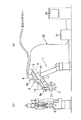
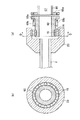
【解決手段】 導管66の一端に設けられたケーブルホルダ68に溶接トーチ側のホルダ23がベアリング15を用いた軸受け機構14を介して取り付けられ、導管66は導管66自身の長手方向軸の周りで回転可能な状態で、溶接トーチ2に結合される。導管66のワイヤ送給装置側の端部についても同様の接続構造が採用できる。導管66にかかるねじりのストレスの大半は回転運動によって逃がされ、導管66の疲労が防止できる。導管66内には、溶接ワイヤ用ライナを収容したアシストガス用チューブと、複数本の溶接電流用導電体を束ねた可動用多芯ケーブルが別々に通される。可動用多芯ケーブルなどを溶接トーチ側または前記ワイヤ送給装置側で固定部に固定しても良く、導管断面内での位置をガイド部材で拘束しても良い。
【選択図】 図5
Description
また、各線条体の径を細くできるので、内部空間67の確保のために導管66を特に細くする必要もない。更に、各線条体は導管66内部で動くことはあっても、導管66でおおわれて適切に拘束されているので、周囲物体との干渉性もそれほど悪化しない。
2、2a、2b 溶接トーチ
3、3a、3b トーチケーブル(従来)
4 ワイヤ送給装置
5 支持ベース
6 トーチケーブル(実施形態)
6a トーチケーブルのトーチ側端部
6b トーチケーブルのワイヤ送給装置側端部
10 前腕基部
11 第1手首要素
12 第2手首要素
13 ケーブルガイド
14、16 軸受け機構
15、17 ベアリング
23 トーチ側ホルダ
24 溶接トーチ接続部材
24a チューブ接続部
25 芯線圧着端子
26 固定ボルト
27 クランプ用板金
28 ナイロンバンド
29 ガイド部材
29a、29b 透孔
31、61 溶接ワイヤ
32、62 ライナ
33、63 ガスホース(チューブ)
34、64 導電体
41 ワイヤ送給装置側ホルダ
41a ワイヤ送給装置側ホルダのフランジ部
42 トーチケーブルを通す穴
65 可動用多芯ケーブル
65a 可動用多芯ケーブルのシース付部
66 導管
66a、66b 導管端部のフランジ部材
67 導管の内部空間
68、69 トーチケーブル側ホルダ(ケーブルホルダ)
68a、69a トーチケーブル側ホルダのフランジ部
68b、69b 固定ネジ
Claims (4)
- ロボット前腕の先端部に取付けられた溶接トーチと、前記ロボット前腕上に設けられて前記溶接トーチに溶接ワイヤを送給するワイヤ送給装置との間に配備される複数の線条体を処理する、アーク溶接ロボットの溶接トーチ用線条体処理構造において、
前記複数の線条体は、溶接ワイヤ用ライナ、アシストガス用チューブ及び溶接電流用導電体を含んでおり、
前記複数の線条体は可撓性の導管によって覆われており、
前記導管の一端は前記溶接トーチ側の第1の接続部で前記溶接トーチに接続されるとともに、前記導管の他端は前記ワイヤ送給装置側の第2の接続部で前記ワイヤ送給装置に接続されており、
前記第1の接続部と前記第2の接続部の内の少なくとも一方において、前記導管は、該導管の長手軸周りに回転可能に支持されていることを特徴とする、アーク溶接ロボットの溶接トーチ用線条体処理構造。 - 前記導管内において、前記溶接電流用導電体は、前記溶接ワイヤ用ライナ及び前記アシストガス用チューブと分離して配置されていることを特徴とする、請求項1に記載のアーク溶接ロボットの溶接トーチ用線条体処理構造。
- 前記複数の線条体は、前記第1の接続部及び前記第2の接続部の内の少なくとも一方において、前記溶接トーチまたは前記ワイヤ送給装置側に設けた固定部に固定されていることを特徴とする、請求項1または請求項2に記載のアーク溶接ロボットの溶接トーチ用線条体処理構造。
- 前記複数の線条体の内の少なくとも一部は、前記導管内の少なくとも1個所で、前記導管断面内での位置を拘束するガイド部材に通されていることを特徴とする、請求項1乃至請求項3の内のいずれか1項に記載のアーク溶接ロボットの溶接トーチ用線条体処理構造。
Priority Applications (5)
| Application Number | Priority Date | Filing Date | Title |
|---|---|---|---|
| JP2004084917A JP4301984B2 (ja) | 2004-03-23 | 2004-03-23 | アーク溶接ロボットの溶接トーチ用線条体処理構造 |
| EP05005897A EP1579963B1 (en) | 2004-03-23 | 2005-03-17 | Arc welding robot with umbilical-member managing structure |
| DE602005005537T DE602005005537T2 (de) | 2004-03-23 | 2005-03-17 | Bogenschweissroboter mit einer Anordnung zum Führen von Versorgungsleitungen |
| US11/085,036 US7196285B2 (en) | 2004-03-23 | 2005-03-22 | Structure for managing umbilical member of welding torch in arc welding robot |
| CNB2005100569102A CN100374235C (zh) | 2004-03-23 | 2005-03-23 | 电弧焊机器人的焊接炬用管线的处理构造 |
Applications Claiming Priority (1)
| Application Number | Priority Date | Filing Date | Title |
|---|---|---|---|
| JP2004084917A JP4301984B2 (ja) | 2004-03-23 | 2004-03-23 | アーク溶接ロボットの溶接トーチ用線条体処理構造 |
Publications (2)
| Publication Number | Publication Date |
|---|---|
| JP2005271003A true JP2005271003A (ja) | 2005-10-06 |
| JP4301984B2 JP4301984B2 (ja) | 2009-07-22 |
Family
ID=34858402
Family Applications (1)
| Application Number | Title | Priority Date | Filing Date |
|---|---|---|---|
| JP2004084917A Expired - Lifetime JP4301984B2 (ja) | 2004-03-23 | 2004-03-23 | アーク溶接ロボットの溶接トーチ用線条体処理構造 |
Country Status (5)
| Country | Link |
|---|---|
| US (1) | US7196285B2 (ja) |
| EP (1) | EP1579963B1 (ja) |
| JP (1) | JP4301984B2 (ja) |
| CN (1) | CN100374235C (ja) |
| DE (1) | DE602005005537T2 (ja) |
Cited By (7)
| Publication number | Priority date | Publication date | Assignee | Title |
|---|---|---|---|---|
| EP2022609A1 (en) | 2007-07-30 | 2009-02-11 | Fanuc Ltd | Industrial robot with conduit for an umbilical-member |
| JP2015033749A (ja) * | 2013-08-09 | 2015-02-19 | ヤマハ発動機株式会社 | ロボットアームの配線構造 |
| DE102016000106A1 (de) | 2015-01-14 | 2016-07-14 | Fanuc Corporation | Verbundkabel, das in einem Industrieroboter montiert ist |
| KR20180027766A (ko) * | 2016-09-07 | 2018-03-15 | 김오갑 | 서브머지드 아크 용접용 플럭스 회수호스 지지장치 |
| KR101858536B1 (ko) * | 2016-06-09 | 2018-05-17 | 대우조선해양 주식회사 | 로봇용 용접토치 |
| KR101875787B1 (ko) * | 2016-09-12 | 2018-07-06 | 대우조선해양 주식회사 | 협소공간 용접을 위한 로봇용 착탈식 회전용접토치 |
| WO2021235347A1 (ja) * | 2020-05-21 | 2021-11-25 | ファナック株式会社 | 産業用ロボット |
Families Citing this family (10)
| Publication number | Priority date | Publication date | Assignee | Title |
|---|---|---|---|---|
| JP4168008B2 (ja) * | 2004-06-04 | 2008-10-22 | ファナック株式会社 | 産業用ロボットの線条体処理構造 |
| JP4233503B2 (ja) * | 2004-09-06 | 2009-03-04 | ファナック株式会社 | アーク溶接ロボットのトーチケーブル処理構造 |
| DE102008019327B4 (de) * | 2008-04-16 | 2011-12-01 | Tbi Industries Gmbh | Schlauchpaketanordnung |
| US8987637B1 (en) * | 2010-10-21 | 2015-03-24 | The Reliable Automatic Sprinkler Co, Inc. | Welding torch oscillator with motorized pitch control |
| CN102452079A (zh) * | 2010-10-27 | 2012-05-16 | 鸿富锦精密工业(深圳)有限公司 | 机器人臂部件 |
| AU2013209396B2 (en) * | 2012-01-19 | 2016-07-07 | Victor Equipment Company | Universal conduit assembly for a welding torch |
| EP2835226A1 (en) * | 2013-08-09 | 2015-02-11 | Yamaha Hatsudoki Kabushiki Kaisha | Wiring structure for robot arm |
| CN105058426B (zh) * | 2015-08-18 | 2017-06-13 | 埃夫特智能装备股份有限公司 | 工业机器人用外围管线安装旋转底座及其装配方法 |
| JP6441255B2 (ja) | 2016-04-07 | 2018-12-19 | ファナック株式会社 | ロボットの線条体処理構造 |
| US10603738B2 (en) * | 2016-11-14 | 2020-03-31 | Electron Beam Technologies, Inc. | Cable for arc welder |
Family Cites Families (4)
| Publication number | Priority date | Publication date | Assignee | Title |
|---|---|---|---|---|
| JPH0528563A (ja) | 1991-07-18 | 1993-02-05 | Nec Corp | 光磁気記録再生方法 |
| EP1163986B1 (de) * | 2000-06-15 | 2008-03-12 | KUKA Roboter GmbH | Vorrichtung zum Festlegen eines Kabelführungsschlauchs |
| DE10141407A1 (de) * | 2001-04-19 | 2002-10-31 | Ernst & Engbring Gmbh & Co Kg | Vorrichtung zum Halten eines Leitungsbündels bei einem Roboter |
| JP4001224B2 (ja) | 2002-02-08 | 2007-10-31 | 株式会社安川電機 | アーク溶接ケーブル |
-
2004
- 2004-03-23 JP JP2004084917A patent/JP4301984B2/ja not_active Expired - Lifetime
-
2005
- 2005-03-17 EP EP05005897A patent/EP1579963B1/en active Active
- 2005-03-17 DE DE602005005537T patent/DE602005005537T2/de active Active
- 2005-03-22 US US11/085,036 patent/US7196285B2/en active Active
- 2005-03-23 CN CNB2005100569102A patent/CN100374235C/zh active Active
Cited By (10)
| Publication number | Priority date | Publication date | Assignee | Title |
|---|---|---|---|---|
| EP2022609A1 (en) | 2007-07-30 | 2009-02-11 | Fanuc Ltd | Industrial robot with conduit for an umbilical-member |
| US8020466B2 (en) | 2007-07-30 | 2011-09-20 | Fanuc Ltd | Umbilical-member processing structure for industrial robot |
| JP2015033749A (ja) * | 2013-08-09 | 2015-02-19 | ヤマハ発動機株式会社 | ロボットアームの配線構造 |
| DE102016000106A1 (de) | 2015-01-14 | 2016-07-14 | Fanuc Corporation | Verbundkabel, das in einem Industrieroboter montiert ist |
| US9717168B2 (en) | 2015-01-14 | 2017-07-25 | Fanuc Corporation | Composite cable mounted in industrial robot |
| KR101858536B1 (ko) * | 2016-06-09 | 2018-05-17 | 대우조선해양 주식회사 | 로봇용 용접토치 |
| KR20180027766A (ko) * | 2016-09-07 | 2018-03-15 | 김오갑 | 서브머지드 아크 용접용 플럭스 회수호스 지지장치 |
| KR101875787B1 (ko) * | 2016-09-12 | 2018-07-06 | 대우조선해양 주식회사 | 협소공간 용접을 위한 로봇용 착탈식 회전용접토치 |
| WO2021235347A1 (ja) * | 2020-05-21 | 2021-11-25 | ファナック株式会社 | 産業用ロボット |
| JP7453362B2 (ja) | 2020-05-21 | 2024-03-19 | ファナック株式会社 | 産業用ロボット |
Also Published As
| Publication number | Publication date |
|---|---|
| EP1579963B1 (en) | 2008-03-26 |
| CN100374235C (zh) | 2008-03-12 |
| US7196285B2 (en) | 2007-03-27 |
| US20050211686A1 (en) | 2005-09-29 |
| EP1579963A1 (en) | 2005-09-28 |
| CN1672853A (zh) | 2005-09-28 |
| JP4301984B2 (ja) | 2009-07-22 |
| DE602005005537T2 (de) | 2009-04-16 |
| DE602005005537D1 (de) | 2008-05-08 |
Similar Documents
| Publication | Publication Date | Title |
|---|---|---|
| JP4301984B2 (ja) | アーク溶接ロボットの溶接トーチ用線条体処理構造 | |
| JP4653427B2 (ja) | アーク溶接ロボットのトーチケーブル処理構造 | |
| US7202442B2 (en) | Cable arrangement for robot arm, and industrial robot utilizing the same | |
| US20210060765A1 (en) | Robot | |
| JP5001917B2 (ja) | ワイヤ送給装置 | |
| JP4280295B2 (ja) | 産業用ロボット | |
| US6795750B2 (en) | Industrial robot | |
| US20060101936A1 (en) | Managing structure for umbilical member of industrial robot | |
| US20060104791A1 (en) | Umbilical member managing system for industrial robot | |
| JP2007021636A (ja) | 産業用ロボットの線条体処理構造 | |
| KR20000016535A (ko) | 용접 케이블용 변형제거 조립체 | |
| JPH08197482A (ja) | 産業用ロボットのケーブル処理装置 | |
| JP2004306072A (ja) | アーク溶接ロボットにおける溶接ワイヤ等の供給機構 | |
| JP2003230963A (ja) | アーク溶接ケーブル | |
| CA3075293C (en) | Welding cable assembly, welding torch assembly, and robotic welding systems, with a spring mechanically coupled to the cable | |
| JP2009006454A (ja) | 溶接ロボットにおけるワイヤ送給装置の設置方法、溶接ロボットにおけるワイヤ送給装置の設置構造及び溶接ロボット | |
| JP2010264525A (ja) | アーク溶接ロボットのケーブル配設構造 | |
| KR20170139293A (ko) | 로봇용 용접토치 | |
| US3999033A (en) | Arc welding torch having a flexible wire guide assembly | |
| JP5109906B2 (ja) | ワイヤー送給チューブ、ワイヤー送給装置、及び、アーク溶接装置 | |
| KR200449943Y1 (ko) | 가스 용접기의 케이블 | |
| WO2021192139A1 (ja) | ケーブルハーネス、ケーブルハーネスの製造方法及びケーブルハーネスを有する産業用ロボット | |
| JPS5830857B2 (ja) | 溶接ワイヤ送給装置 | |
| JPS6326271A (ja) | ア−ク溶接用ワイヤ自動送給装置 | |
| JP2010075948A (ja) | コンジットケーブル |
Legal Events
| Date | Code | Title | Description |
|---|---|---|---|
| A977 | Report on retrieval |
Free format text: JAPANESE INTERMEDIATE CODE: A971007 Effective date: 20070424 |
|
| A131 | Notification of reasons for refusal |
Free format text: JAPANESE INTERMEDIATE CODE: A131 Effective date: 20070501 |
|
| A521 | Written amendment |
Free format text: JAPANESE INTERMEDIATE CODE: A523 Effective date: 20070629 |
|
| A02 | Decision of refusal |
Free format text: JAPANESE INTERMEDIATE CODE: A02 Effective date: 20070724 |
|
| A521 | Written amendment |
Free format text: JAPANESE INTERMEDIATE CODE: A523 Effective date: 20070920 |
|
| A911 | Transfer of reconsideration by examiner before appeal (zenchi) |
Free format text: JAPANESE INTERMEDIATE CODE: A911 Effective date: 20070926 |
|
| A912 | Removal of reconsideration by examiner before appeal (zenchi) |
Free format text: JAPANESE INTERMEDIATE CODE: A912 Effective date: 20081107 |
|
| A521 | Written amendment |
Free format text: JAPANESE INTERMEDIATE CODE: A523 Effective date: 20090319 |
|
| A01 | Written decision to grant a patent or to grant a registration (utility model) |
Free format text: JAPANESE INTERMEDIATE CODE: A01 |
|
| A61 | First payment of annual fees (during grant procedure) |
Free format text: JAPANESE INTERMEDIATE CODE: A61 Effective date: 20090421 |
|
| FPAY | Renewal fee payment (event date is renewal date of database) |
Free format text: PAYMENT UNTIL: 20120501 Year of fee payment: 3 |
|
| R150 | Certificate of patent or registration of utility model |
Ref document number: 4301984 Country of ref document: JP Free format text: JAPANESE INTERMEDIATE CODE: R150 Free format text: JAPANESE INTERMEDIATE CODE: R150 |
|
| FPAY | Renewal fee payment (event date is renewal date of database) |
Free format text: PAYMENT UNTIL: 20120501 Year of fee payment: 3 |
|
| FPAY | Renewal fee payment (event date is renewal date of database) |
Free format text: PAYMENT UNTIL: 20130501 Year of fee payment: 4 |
|
| FPAY | Renewal fee payment (event date is renewal date of database) |
Free format text: PAYMENT UNTIL: 20130501 Year of fee payment: 4 |
|
| FPAY | Renewal fee payment (event date is renewal date of database) |
Free format text: PAYMENT UNTIL: 20140501 Year of fee payment: 5 |