JP2005198730A - Game machine - Google Patents

Game machine Download PDF

Info

Publication number
JP2005198730A
JP2005198730A JP2004006087A JP2004006087A JP2005198730A JP 2005198730 A JP2005198730 A JP 2005198730A JP 2004006087 A JP2004006087 A JP 2004006087A JP 2004006087 A JP2004006087 A JP 2004006087A JP 2005198730 A JP2005198730 A JP 2005198730A
Authority
JP
Japan
Prior art keywords
effect
reels
game
reel
combination
Prior art date
Legal status (The legal status is an assumption and is not a legal conclusion. Google has not performed a legal analysis and makes no representation as to the accuracy of the status listed.)
Pending
Application number
JP2004006087A
Other languages
Japanese (ja)
Inventor
Takahiro Nishisaka
貴大 西坂
Current Assignee (The listed assignees may be inaccurate. Google has not performed a legal analysis and makes no representation or warranty as to the accuracy of the list.)
Sammy Corp
Samy KK
Original Assignee
Sammy Corp
Samy KK
Priority date (The priority date is an assumption and is not a legal conclusion. Google has not performed a legal analysis and makes no representation as to the accuracy of the date listed.)
Filing date
Publication date
Application filed by Sammy Corp, Samy KK filed Critical Sammy Corp
Priority to JP2004006087A priority Critical patent/JP2005198730A/en
Publication of JP2005198730A publication Critical patent/JP2005198730A/en
Pending legal-status Critical Current

Links

Images

Abstract

<P>PROBLEM TO BE SOLVED: To provide a start lever with a function of allowing a player to select a presentation in a plurality of operation directions as other meanings on a game, in addition to a function of commanding a start of the game of the game machine, by allowing the start lever to be displaced in the plurality of directions. <P>SOLUTION: The start lever 41 has a shaft part 41a, which has a projection 41b at one end for a player to grip or to perform a hitting operation, a disk-shaped detected member 41c at the other end, and an elastic member 41d at the center of the shaft part 41a. When the player operates the projection 41b and releases the projection 41b afterward, the shaft part 41a is returned to the initial position by the elastic member 41d for returning the shaft part 41a to the center position. In addition, the start lever also has displacement detecting parts 111a-111d at four upper, lower, left and right positions corresponding to the detected member 41c. <P>COPYRIGHT: (C)2005,JPO&NCIPI

Description

本発明は、複数のリールにより行われる遊技の演出を行う遊技機に関する。   The present invention relates to a gaming machine that produces a game performed by a plurality of reels.

従来から、複数種類の図柄が表示された複数の遊技用リールと、この複数の遊技用リールの回転動作を個々に停止させるための複数のストップスイッチとが設けられたスロットマシンがある。   Conventionally, there is a slot machine provided with a plurality of gaming reels on which a plurality of types of symbols are displayed, and a plurality of stop switches for individually stopping the rotating operations of the plurality of gaming reels.

かかるスロットマシンでは、複数のストップスイッチを遊技者が操作すると、操作したストップスイッチに対応する遊技用リールの回転動作が停止して、その遊技用リールに表示されている図柄が有効ライン上に停止する。このようにして、全ての遊技用リールの回転動作が停止すると、有効ライン上に図柄の組合せが表示され、この表示された図柄の組合せに応じて、遊技者に対して所定の遊技価値(メダルの払い出しなど)を与えるようにしている。   In such a slot machine, when a player operates a plurality of stop switches, the rotation operation of the game reel corresponding to the operated stop switch stops, and the symbols displayed on the game reel stop on the active line. To do. In this way, when all the gaming reels have stopped rotating, a symbol combination is displayed on the active line, and a predetermined game value (medal) is given to the player according to the displayed symbol combination. Etc.).

また、このようなスロットマシンでは、遊技機(スロットマシン)は、リールに図柄を表示し、リールの停止時の図柄の組合せによって遊技結果を表示するとともに、各種の演出出力装置(ランプ、スピーカ、画像表示装置等)によって演出を出力し、その出力した演出の内容によって、役の抽選結果等を報知することが一般的となっている。   In such a slot machine, a gaming machine (slot machine) displays a symbol on a reel, displays a game result by a combination of symbols when the reel is stopped, and various effect output devices (lamps, speakers, It is common to output an effect by an image display device or the like, and to notify the result of the lottery of the role or the like according to the content of the output effect.

特開2001−187179号公報JP 2001-187179 A

しかしながら、上記したスロットマシンでは、各種の演出は当該スロットマシン自らによる選択・決定によりなされるものであり、遊技者は演出に対して飽くまで受身であるのが常識とされていた。従って、遊技者自身が遊技・演出に参加できるかたちのスロットマシンが望まれる現況にある。   However, in the slot machine described above, various effects are made by selection / determination by the slot machine itself, and it has been common knowledge that the player is passive until he gets tired of the effects. Therefore, there is a demand for a slot machine in which the player himself can participate in the game / production.

本発明は、上記した問題に鑑みてなされたものであり、遊技者が演出を選択可能とし、遊技者には遊技中に見たいと欲した演出を自ら選択する機会が与えられ、今までにない新たな遊技興趣を創出することを実現する遊技機を提供することを目的とする。   The present invention has been made in view of the above-described problems, and allows the player to select an effect, and the player is given the opportunity to select the effect he desires to see during the game. An object is to provide a gaming machine that realizes the creation of a new gaming entertainment.

更に、スタートレバーを複数方向に対して変位可能とすることにより、スタートレバーに当該遊技機の遊技開始を指示する機能に加え、複数の操作方向に他の遊技上の意味として遊技者による演出選択機能を持たせることができるようになる。この構成により、遊技者には遊技中に見たいと欲した演出を自ら選択する機会が与えられ、今までにない新たな遊技興趣を創出することを可能とする。更にはスタートレバーの摩耗が方向毎にある程度均一化することを可能として、スタートレバーの寿命を長期化することが期待できる遊技機を提供することを目的とする。   Furthermore, by making the start lever displaceable in multiple directions, in addition to the function of instructing the start lever to start the game of the gaming machine, the player can select effects as other game meanings in multiple operation directions. It becomes possible to have a function. With this configuration, the player is given the opportunity to select the desired production he / she wants to see during the game, and it is possible to create an unprecedented new game entertainment. It is another object of the present invention to provide a gaming machine that can make wear of the start lever uniform to some extent for each direction, and can prolong the life of the start lever.

このような目的を達成するため、本発明の遊技機は、複数種類の図柄を表示し、停止時の図柄の組み合わせにより遊技結果を表示するための複数の遊技用リール(31)と、遊技者の操作により、前記遊技用リール(31)の始動し得るとともに、複数の方向に変位可能なスタートレバー(41)と、前記遊技用リール(31)に対応して設けられ、遊技者の操作に基づいて前記遊技用リール(31)の回転を停止させるためのストップスイッチ(42)と、前記遊技における役の抽選を行う役抽選手段(63)と、前記役抽選手段(63)により行われる役の抽選結果及び前記ストップスイッチ(42)の操作に基づいて前記遊技用リールの駆動制御を行う遊技用リール制御手段(69)と、各種の演出を表出するための演出表示手段(例えば51)と、前記演出表示手段(例えば51)の表示制御を行う演出表示制御手段(例えば90,81,82)とを有し、前記スタートレバー(41)は、前記変位を検出可能な変位検出部(111)を前記複数の方向のうち少なくとも2方向にそれぞれ備え、前記各変位検出部(111)に対応した前記演出の選択が可能とされており、遊技者による前記選択の結果を前記変位検出部(111)からの入力信号として前記演出表示制御手段(例えば90,81,82)に指示する。   In order to achieve such an object, the gaming machine of the present invention displays a plurality of types of symbols, and a plurality of gaming reels (31) for displaying a gaming result by a combination of symbols when stopped, and a player The game reel (31) can be started by the above operation, and is provided corresponding to the start lever (41) that can be displaced in a plurality of directions and the game reel (31). Based on the stop switch (42) for stopping the rotation of the gaming reel (31) based on the above, a role lottery means (63) for lottery of the role in the game, and a role performed by the role lottery means (63) Game reel control means (69) for controlling the driving of the gaming reel based on the lottery result and the operation of the stop switch (42), and effect display means for displaying various effects (example) 51) and effect display control means (for example, 90, 81, 82) for controlling the display of the effect display means (for example, 51), and the start lever (41) is a displacement capable of detecting the displacement. A detection unit (111) is provided in each of at least two of the plurality of directions, and the selection of the effect corresponding to each displacement detection unit (111) is possible, and the result of the selection by the player is The effect display control means (for example, 90, 81, 82) is instructed as an input signal from the displacement detector (111).

かかる構成によれば、複数の方向に変位可能なスタートレバー(41)に遊技開始指示機能に加えて遊技者による演出の選択機能が実現し、遊技者には見たいと欲した演出を遊技中に自ら選択する機会が与えられ、スタートレバー(41)を用いた新たな遊技興趣を創出することが可能となる。しかもこの場合、遊技者によりスタートレバー(41)を複数の各方向にそれぞれ変位させる頻度は必然的に高まり、スタートレバー(41)の摩耗が方向毎にある程度均一化することが可能なり、スタートレバー(41)の寿命の長期化が期待される。   According to such a configuration, the start lever (41) that can be displaced in a plurality of directions realizes a function for selecting an effect by the player in addition to the function for instructing the start of the game. An opportunity to select himself / herself is given, and it becomes possible to create a new game entertainment using the start lever (41). In addition, in this case, the frequency with which the player displaces the start lever (41) in each of a plurality of directions inevitably increases, and the wear of the start lever (41) can be made uniform to some extent in each direction. (41) is expected to prolong the life.

本発明では、前記演出表示手段の一例として、複数種類の図柄を表示し、その回転動作を含む各種の演出を行うための演出用リール(51)を採用し、前記演出表示制御手段の一例として、前記演出用リール(51)が行う前記演出を選択する演出選択手段(例えば90)と、前記演出選択手段(例えば90)により選択された結果に基づいて前記演出用リール(51)の回転態様を制御する演出用リール制御手段(例えば85)とを採用して、前記演出選択手段(例えば90)により遊技者選択演出が選択された場合には、前記演出用リール制御手段(例えば85)は、前記スタートレバー(41)による前記選択の結果に基づいて前記演出用リール(51)の回転態様を制御するように構成する。   In the present invention, as an example of the effect display means, an effect reel (51) for displaying various kinds of symbols and performing various effects including its rotating operation is adopted. The effect selection means (for example, 90) for selecting the effect performed by the effect reel (51), and the rotation mode of the effect reel (51) based on the result selected by the effect selection means (for example, 90) When the player selection effect is selected by the effect selection means (for example, 90), the effect reel control means (for example, 85) is used. The rotation mode of the effect reel (51) is controlled based on the result of the selection by the start lever (41).

かかる構成によれば、遊技用リール(31)と共に演出用リール(51)を備えた遊技機に本発明を適用し、特にスタートレバー(41)の複数方向への操作により遊技者に演出用リール(51)の回転態様を選択させるという全く新しい遊技興趣を創出し、遊技の趣向性を大幅に高めることが可能となる。具体的には、前記スタートレバー(41)による前記選択に対応して、前記各演出用リール(51)の回転方向の組み合わせが異なるような態様が考えられる。   According to such a configuration, the present invention is applied to a gaming machine provided with an effect reel (51) together with a game reel (31), and in particular, an effect reel is provided to the player by operating the start lever (41) in a plurality of directions. It is possible to create a completely new game entertainment theme in which the rotation mode of (51) is selected, and to greatly improve the game preference. Specifically, it is conceivable that the combinations of the rotation directions of the production reels (51) are different corresponding to the selection by the start lever (41).

本発明の遊技機の別態様は、複数種類の図柄を表示し、停止時の図柄の組み合わせにより遊技結果を表示するための複数の遊技用リール(31)と、遊技者の操作により、前記遊技用リール(31)の始動を開始するスタートレバー(41)と、複数の前記遊技用リール(31)に対応して設けられ、遊技者の操作に基づいて前記遊技用リール(31)の回転を停止させるための複数のストップスイッチ(42)と、前記遊技における役の抽選を行う役抽選手段(63)と、前記役抽選手段(63)により行われる役の抽選結果及び前記ストップスイッチ(42)の操作に基づいて前記遊技用リール(31)の駆動制御を行う遊技用リール制御手段(69)と、各種の演出を表出するための演出表示手段(例えば51)と、前記演出表示手段(例えば51)の表示制御を行う演出表示制御手段(例えば90,81,82)と、複数の操作ボタン(例えば48)を有し、遊技者の操作により前記各操作ボタン(例えば48)の入力に応じた演出選択を前記演出表示制御手段(例えば90,81,82)に指示する演出選択指示手段(例えば48L、48C、48Rからなる手段)とを有する。   According to another aspect of the gaming machine of the present invention, a plurality of game reels (31) for displaying a plurality of types of symbols and displaying a game result by a combination of symbols at the time of stop, and the game by the player's operation A start lever (41) for starting the starting reel (31) and a plurality of the gaming reels (31), and the gaming reel (31) is rotated based on a player's operation. A plurality of stop switches (42) for stopping, a combination lottery means (63) for performing a lottery of the combination in the game, and a lottery result of the combination performed by the combination lottery means (63) and the stop switch (42) A game reel control means (69) for controlling the driving of the gaming reel (31) based on the operation of the game, an effect display means (for example, 51) for expressing various effects, and the effect display means. For example, it has an effect display control means (for example, 90, 81, 82) for performing the display control of 51) and a plurality of operation buttons (for example, 48). Production selection instruction means (for example, means comprising 48L, 48C, and 48R) for instructing the production display control means (for example, 90, 81, 82) to perform the corresponding production selection.

かかる構成によれば、遊技者による操作ボタン(例えば48)の操作という簡便且つ容易な操作法により演出の選択機能が実現し、遊技者には見たいと欲した演出を遊技中に自ら選択する機会が与えられ、新たな遊技興趣を創出することができ、遊技の趣向性を大幅に高めることが可能となる。   According to such a configuration, an effect selection function is realized by a simple and easy operation method of operation of an operation button (for example, 48) by the player, and the player himself / herself selects an effect he / she wants to see during the game. Opportunities are given, new game entertainment can be created, and the game preference can be greatly enhanced.

本発明では、前記演出表示手段の一例として、複数種類の図柄を表示し、その回転動作を含む各種の演出を行うための演出用リール(51)を採用し、前記演出表示制御手段の一例として、前記演出用リール(51)が行う前記演出を選択する演出選択手段(例えば90)と、前記演出選択手段(例えば90)により選択された結果に基づいて前記演出用リール(51)の回転態様を制御する演出用リール制御手段(例えば85)とを採用して、前記演出選択手段(例えば90)により遊技者選択演出が選択された場合には、前記演出用リール制御手段(例えば85)は、前記操作ボタン(例えば48)による前記選択の結果に基づいて前記演出用リール(51)の回転態様を制御するように構成する。   In the present invention, as an example of the effect display means, an effect reel (51) for displaying various kinds of symbols and performing various effects including its rotating operation is adopted. The effect selection means (for example, 90) for selecting the effect performed by the effect reel (51), and the rotation mode of the effect reel (51) based on the result selected by the effect selection means (for example, 90) When the player selection effect is selected by the effect selection means (for example, 90), the effect reel control means (for example, 85) is used. The rotation mode of the effect reel (51) is controlled based on the result of the selection by the operation button (for example, 48).

かかる構成によれば、遊技用リール(31)と共に演出用リール(51)を備えた遊技機に本発明を適用し、特に操作ボタン(例えば48)の操作により遊技者に演出用リール(51)の回転態様を選択させるという全く新しい遊技興趣を創出し、遊技の趣向性を大幅に高めることが可能となる。具体的には、前記操作ボタン(例えば48)による前記選択に対応して、前記各演出用リール(51)の回転方向の組み合わせが異なるような態様が考えられる。   According to such a configuration, the present invention is applied to a gaming machine provided with an effect reel (51) together with a game reel (31), and in particular, the effect reel (51) is provided to the player by operating an operation button (for example, 48). It is possible to create a completely new game entertainment that allows the user to select the rotation mode of the game, and to greatly enhance the game preference. Specifically, it is conceivable that the combinations of the rotation directions of the production reels (51) are different corresponding to the selection by the operation button (for example, 48).

本発明の遊技機によれば、遊技者が演出を選択可能とし、遊技者には見たいと欲した演出を遊技中に自ら選択する機会が与えられ、今までにない新たな遊技興趣を創出することを実現することができる。   According to the gaming machine of the present invention, the player can select an effect, and the player is given the opportunity to select the effect he / she wants to see during the game, creating a new game entertainment that has never existed before Can be realized.

また、本発明の遊技機によれば、スタートレバーを複数方向に対して変位可能とすることにより、スタートレバーに当該遊技機の遊技開始を指示する機能に加え、複数の操作方向に他の遊技上の意味として遊技者による演出選択機能を持たせる。この構成により、遊技者には見たいと欲した演出を自ら選択する機会が与えられ、今までにない新たな遊技興趣を創出することを可能とする。更にはスタートレバーの摩耗が方向毎にある程度均一化することを可能として、スタートレバーの寿命を長期化することが期待できる。   Further, according to the gaming machine of the present invention, by enabling the start lever to be displaced in a plurality of directions, in addition to the function of instructing the start lever to start the game of the gaming machine, other games in a plurality of operation directions. As an upper meaning, an effect selection function by the player is provided. With this configuration, the player is given an opportunity to select the desired production he / she wants to see, and it is possible to create an unprecedented new gaming interest. Furthermore, the wear of the start lever can be made uniform to some extent for each direction, and the life of the start lever can be expected to be extended.

次に、図面を参照しながら、本発明の一実施形態について説明する。
図1は、本実施形態によるスロットマシン(遊技機)10の外観を示す正面図である。
Next, an embodiment of the present invention will be described with reference to the drawings.
FIG. 1 is a front view showing an appearance of a slot machine (game machine) 10 according to the present embodiment.

(スロットマシンの概略構成)
図1に示すように、スロットマシン10の筐体は、基体11と、基体11の前面に取り付けられるフロントパネル12とから構成されている。なお、図1では、基体11の詳細な構成を省略している。
また、スロットマシン10の筐体の内部には、遊技用リールユニット30及び演出用リールユニット50が配置されている。
(Schematic configuration of slot machine)
As shown in FIG. 1, the housing of the slot machine 10 includes a base body 11 and a front panel 12 attached to the front surface of the base body 11. In FIG. 1, the detailed structure of the base 11 is omitted.
In addition, a gaming reel unit 30 and an effect reel unit 50 are disposed inside the casing of the slot machine 10.

基体11は、前面が開口された箱形に形成されている。この基体11の内部において、下方部には、電源ユニット及びメダルを貯留しておくホッパーを含むメダル払出装置47(図12を参照)が設けられている。
また、これらの電源ユニット及びメダル払出装置47の上方には、支持板が設けられており、この支持板の上に演出用リールユニット50が搭載されている。
The base 11 is formed in a box shape having an open front surface. Inside the base 11, a medal payout device 47 (see FIG. 12) including a power supply unit and a hopper for storing medals is provided in a lower portion.
Further, a support plate is provided above the power supply unit and the medal payout device 47, and an effect reel unit 50 is mounted on the support plate.

一方、フロントパネル12は、基体11の前面を覆うように基体11に開閉可能に取り付けられたものである。
フロントパネル12の前面側(遊技者側)には、スタートスイッチ41と、ストップスイッチ42L、42C、及び42Rと、ベットスイッチ45と、貯留解除スイッチ46とを備えた操作スイッチ40や、メダル投入口43や、メダル受け皿44等が配置されている。また、操作スイッチ40の上方部であってフロントパネル12の中央部には、透明な第2表示窓12bが設けられている。この第2表示窓12bから、基体11内部の演出用リール51L、51C、及び51Rの一部が透視できるように構成されている。また、図1において、第2表示窓12bの右側には、液晶表示装置13が設けられている。
On the other hand, the front panel 12 is attached to the base 11 so as to be openable and closable so as to cover the front surface of the base 11.
On the front side (player side) of the front panel 12, an operation switch 40 including a start switch 41, stop switches 42L, 42C, and 42R, a bet switch 45, and a storage release switch 46, a medal insertion slot, 43, a medal tray 44, and the like are arranged. A transparent second display window 12b is provided above the operation switch 40 and in the center of the front panel 12. From the second display window 12b, a part of the production reels 51L, 51C, and 51R inside the base body 11 can be seen through. In FIG. 1, a liquid crystal display device 13 is provided on the right side of the second display window 12b.

さらに、図1に示すように、フロントパネル12の上方部、特に本実施形態では、第2表示窓12bに対して操作スイッチ40から遠ざかる側には、第1表示窓12aが設けられている。遊技用リールユニット30は、フロントパネル12の裏面側において、第1表示窓12aが形成された領域の後方に配置されている。   Further, as shown in FIG. 1, a first display window 12a is provided on the upper portion of the front panel 12, particularly in the present embodiment, on the side away from the operation switch 40 with respect to the second display window 12b. The gaming reel unit 30 is disposed on the back side of the front panel 12 behind the area where the first display window 12a is formed.

(操作スイッチ)
本実施形態では、スタートスイッチは、遊技者により操作可能な位置に配設されており、遊技用リール31L、31C、及び31Rと、演出用リール51L、51C、及び51Rとを回転させるとき、又は図8に示す演出選択画像13aや図11に示すデモ選択用画像13bに基づいて演出を選択するとき等に操作される。なお、本実施形態では、レバー形態のものをスタートスイッチとして採用している。以下の説明では、スタートスイッチをスタートレバーと称する。
(Operation switch)
In the present embodiment, the start switch is disposed at a position that can be operated by the player, and when the game reels 31L, 31C, and 31R and the effect reels 51L, 51C, and 51R are rotated, or It is operated when an effect is selected based on the effect selection image 13a shown in FIG. 8 or the demo selection image 13b shown in FIG. In this embodiment, a lever type is adopted as the start switch. In the following description, the start switch is referred to as a start lever.

ここで、本実施形態のスタートレバーの構成について説明する。
このスタートレバー41は、複数の異なる方向に変位自在とされており、これら複数の異なる方向のうち、少なくとも2箇所に変位を検出可能な変位検出部を備えて構成されている。以下、変位検出部が上下左右の4箇所に設けられる場合を例示するが、例えば8箇所に設けたり、或いはスタートレバー41は上下左右に変位可能であるが、変位検出部を上下の2箇所に設ける等の構成を採ることもできる。
Here, the configuration of the start lever of the present embodiment will be described.
The start lever 41 is configured to be freely displaceable in a plurality of different directions, and includes a displacement detector that can detect the displacement in at least two of the plurality of different directions. Hereinafter, the case where the displacement detection units are provided at the four locations on the top, bottom, left and right will be exemplified. For example, the displacement detection unit may be provided at eight locations, or the start lever 41 can be displaced vertically and horizontally. It is also possible to adopt a configuration such as providing.

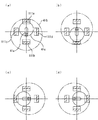
このスタートレバー41の具体的構成例を図2に示す。ここで、図2(a)は右側断面図であり、図2(b)は(a)の破線V−Vに沿った正断面図である。
スタートレバー41はシャフト部41aを有しており、シャフト部41aの一端には遊技者が把持し又は叩く等の操作をする略球状の突起部41bが、シャフト部41aの他端には円盤状に形成された被検出部材41cがそれぞれ設けられるとともに、シャフト部41aの中央部位には弾性部材41dが設けられており、遊技者が突起部41bを操作し、その後遊技者が突起部41bを離した際に、シャフト部41aを中心位置(以下、初期位置と称す)に復帰させるための弾性部材41dによりシャフト部41aが初期位置に復帰するように構成されている。更に、被検出部材41cに対応するように、ここでは上述の変位検出部が図2(b)の上下左右の4箇所に変位検出部111a〜111dとして設けられている。
A specific configuration example of the start lever 41 is shown in FIG. Here, FIG. 2A is a right side sectional view, and FIG. 2B is a front sectional view taken along the broken line VV in FIG.
The start lever 41 has a shaft portion 41a. A substantially spherical protrusion 41b that is operated by a player to grip or hit the shaft portion 41a is formed at one end of the shaft portion 41a, and a disc shape is formed at the other end of the shaft portion 41a. And the elastic member 41d is provided at the central portion of the shaft portion 41a. The player operates the protrusion 41b, and then the player releases the protrusion 41b. In this case, the shaft portion 41a is returned to the initial position by the elastic member 41d for returning the shaft portion 41a to the center position (hereinafter referred to as the initial position). Further, here, the displacement detection units described above are provided as the displacement detection units 111a to 111d at four locations on the top, bottom, left, and right in FIG. 2B so as to correspond to the detected member 41c.

本実施形態における変位検出部111a〜111dは光センサを採用しており、窪み部112には、受光部115と発光部116とが、互いに対向するように形成され、発光部116から受光部115に赤外光が照射されている。
例えば図3(a)に示すように、遊技者が突起部41bを下方向に操作すると、上部位に設けられた検出部111aの窪み部112に被検出部材41cが進入して赤外光が遮断される。これにより、下方向への操作として検出部111aにおいて入力が検出される。同様に、遊技者が突起部41bを上方向に操作した場合には、図3(b)に示すように、下部位に設けられた検出部111bにおいて入力が検出され、遊技者が突起部41bを右方向に操作した場合には、図3(c)に示すように、左部位に設けられた検出部111cにおいて入力が検出され、遊技者が突起部41bを左方向に操作した場合には、図3(d)に示すように、右部位に設けられた検出部111dにおいて入力が検出される。
The displacement detection units 111a to 111d in the present embodiment employ optical sensors, and the light receiving unit 115 and the light emitting unit 116 are formed in the recess 112 so as to face each other. Is irradiated with infrared light.
For example, as shown in FIG. 3A, when the player operates the protrusion 41b downward, the detected member 41c enters the recess 112 of the detection unit 111a provided in the upper part, and infrared light is emitted. Blocked. Thereby, an input is detected in the detection unit 111a as a downward operation. Similarly, when the player operates the protrusion 41b upward, as shown in FIG. 3B, the input is detected by the detection unit 111b provided in the lower part, and the player detects the protrusion 41b. When the player is operated in the right direction, as shown in FIG. 3C, the input is detected by the detection unit 111c provided in the left part, and when the player operates the protrusion 41b in the left direction. As shown in FIG. 3D, the input is detected by the detection unit 111d provided in the right part.

なお、変位検出部としては、上述のように光センサで構成する替わりに、機械的センサを設けても良い。
例えば、図4に示すように、上下左右の4箇所にアクチュエータロットタイプのセンサを取着し、このセンサには検出部113a〜113dが設けられる。検出部113a〜113dは、それぞれ例えば板バネ状の押圧スイッチ114を有しており、被検出部材41cが押圧スイッチ114に当接し押圧することにより押圧スイッチ114が当接部115と接することにより電気的に導通し、入力が検出される。このように構成することで、遊技者は、スタートレバーを操作した時にクリック感を得ることができ、遊技者に対してスタートレバーの操作方向を認識させ易くすることができる。
In addition, as a displacement detection part, you may provide a mechanical sensor instead of comprising with an optical sensor as mentioned above.
For example, as shown in FIG. 4, actuator lot type sensors are attached at four locations, top, bottom, left, and right, and detectors 113 a to 113 d are provided in this sensor. Each of the detectors 113a to 113d includes a leaf spring-like pressing switch 114, for example. The detected member 41c comes into contact with and presses the pressing switch 114, so that the pressing switch 114 comes into contact with the contacting portion 115. And the input is detected. With this configuration, the player can obtain a click feeling when operating the start lever, and can easily make the player recognize the operation direction of the start lever.

そして、本実施形態のスロットマシンでは、スタートレバー41が遊技のスタート指示機能に加えて遊技価値付与機能、即ちこれら変位検出部111a〜111d(又は113a〜113d)からの入力信号に基づいて所要の遊技価値を付与可能な遊技価値付与手段が設けられている。本実施形態のスロットマシンには、スタートレバー41の各方向へ変位に応じて、各種の演出を表出するための演出表示手段、例えば後述する演出用リール51L,51C,51Rの各回転方向を遊技者に選択させる演出をしたり、更には遊技者の選択により演出のデモンストレーションを行う手段が付与されている。   In the slot machine of the present embodiment, the start lever 41 has a game value giving function in addition to the game start instruction function, that is, based on input signals from these displacement detection units 111a to 111d (or 113a to 113d). Game value giving means capable of giving a game value is provided. In the slot machine of the present embodiment, the effect display means for displaying various effects according to the displacement of the start lever 41 in each direction, for example, each rotation direction of the effect reels 51L, 51C, 51R described later. Means are provided for producing an effect to be selected by the player and for demonstrating the effect by selection of the player.

ストップスイッチ42L、42C、及び42Rは、遊技用リール31L、31C、及び31Rと、演出用リール51L、51C、及び51Rとの回転動作を停止させるとき、又は演出選択画像13aやデモ選択用画像13b等を液晶表示装置13に表示させるときに遊技者により操作されるスイッチである。このストップスイッチ42L、42C、及び42Rは、遊技用リール31L、31C、及び31Rと、演出用リール51L、51C、及び51Rとに対応して設けられている。   The stop switches 42L, 42C, and 42R are used to stop the rotation operation of the game reels 31L, 31C, and 31R and the effect reels 51L, 51C, and 51R, or the effect selection image 13a and the demonstration selection image 13b. The switch is operated by the player when the liquid crystal display device 13 is displayed. The stop switches 42L, 42C, and 42R are provided corresponding to the game reels 31L, 31C, and 31R and the effect reels 51L, 51C, and 51R.

なお、後述するように、本実施形態においては、デモンストレーションを行うことが可能な演出を液晶表示装置13に表示し、表示した演出の中から遊技者により選択された演出のデモンストレーションを行うようにしている。そこで、デモンストレーションを行うことが可能な演出を液晶表示装置13に表示させる際にもストップスイッチ42L、42C、及び42Rが使用されるようにしている。   As will be described later, in this embodiment, an effect that can be demonstrated is displayed on the liquid crystal display device 13, and an effect selected by the player from the displayed effects is demonstrated. Yes. Therefore, the stop switches 42L, 42C, and 42R are also used when displaying an effect that can be demonstrated on the liquid crystal display device 13.

ベットスイッチ45は、メダル投入口43から投入された貯留中のメダル、又は入賞によって払い出された貯留中のメダルによって遊技を開始するときに遊技者により操作されるスイッチである。
貯留解除スイッチ46は、貯留中のメダルを払い出す際に、遊技者により操作されるスイッチである。
The bet switch 45 is a switch operated by the player when a game is started with a stored medal inserted from the medal insertion slot 43 or a stored medal paid out by winning.
The storage release switch 46 is a switch operated by the player when paying out the stored medals.

(遊技用リールユニット)
遊技用リールユニット30は、リング状の3つの遊技用リール31L、31C、及び31Rを並設したものを備える。また、遊技用リール31L、31C、及び31Rの回転中心部には、それぞれステッピングモータが連結されており、このステッピングモータの駆動制御によって、遊技用リール31L、31C、及び31Rの回転が制御される。また、各遊技用リール31L、31C、及び31Rの内周の内側には、1つの図柄を背後から照光するためのバックランプ33が固定されている(図1を参照)。
(Game reel unit)
The gaming reel unit 30 includes three ring-shaped gaming reels 31L, 31C, and 31R arranged in parallel. Further, stepping motors are connected to the rotation center portions of the gaming reels 31L, 31C, and 31R, respectively, and the rotation of the gaming reels 31L, 31C, and 31R is controlled by driving control of the stepping motors. . Further, a back lamp 33 for illuminating one symbol from the back is fixed inside the inner circumference of each of the game reels 31L, 31C, and 31R (see FIG. 1).

このようにしてスロットマシン10内に設けられた各遊技用リール31L、31C、及び31Rには、複数種類の図柄(役を構成する図柄等)が印刷されたリールテープが貼付されている。   In this way, a reel tape on which a plurality of types of symbols (such as symbols constituting a role) is printed is affixed to each of the gaming reels 31L, 31C, and 31R provided in the slot machine 10.

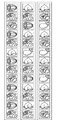
図5は、正面から見て、左、中及び右の各遊技用リール31L、31C、及び31Rの外周面に表示された図柄の配列をそれぞれ展開して示す平面図である。
本実施形態の遊技用リール31L、31C、及び31Rには、それぞれ13個の図柄が表示されている。そして、フロントパネル12の第1表示窓12aから、1つの図柄が見えるように、各遊技用リール31L、31C、及び31Rが配置されている。すなわち、フロントパネル12の第1表示窓12aから、遊技用リール31L、31C、及び31Rの合計3個の図柄が透視できるようにしている。
FIG. 5 is a plan view showing a developed arrangement of symbols displayed on the outer peripheral surfaces of the left, middle and right game reels 31L, 31C, and 31R when viewed from the front.
Thirteen symbols are displayed on each of the game reels 31L, 31C, and 31R of the present embodiment. The game reels 31L, 31C, and 31R are arranged so that one symbol can be seen from the first display window 12a of the front panel 12. That is, a total of three symbols of the gaming reels 31L, 31C, and 31R can be seen through from the first display window 12a of the front panel 12.

図1では、各遊技用リール31L、31C、及び31Rの内周の内側で固定されているバックランプ33を、破線の円によって示している。これらバックランプ33の前方に位置する図柄が、それぞれ第1表示窓12aから透視できる図柄に相当する。   In FIG. 1, the back lamp 33 fixed inside the inner periphery of each game reel 31L, 31C, and 31R is indicated by a broken-line circle. These symbols positioned in front of the back lamp 33 correspond to symbols that can be seen through from the first display window 12a.

また、第1表示窓12aを含む部分には、図柄組合せラインL1が設けられている。図1では、この図柄組合せラインL1を2点鎖線で示している。
ここで、「図柄組合せラインL1」とは、遊技用リール31L、31C、及び31Rの停止時における図柄の並びラインであって、図柄の組合せを形成させるラインである。本実施形態では、水平方向の1本が図柄組合せラインL1として設けられている。
In addition, a symbol combination line L1 is provided in a portion including the first display window 12a. In FIG. 1, the symbol combination line L1 is indicated by a two-dot chain line.
Here, the “symbol combination line L1” is a line of symbols when the game reels 31L, 31C, and 31R are stopped, and is a line that forms a combination of symbols. In the present embodiment, one in the horizontal direction is provided as the symbol combination line L1.

このように、本実施形態では、第1表示窓12aから1つの図柄が見えるように、各遊技用リール31L、31C、及び31Rを配置しているので、図柄組合せラインL1は、1本に設定されている。ただし、図柄組合せラインL1は1本に限定されない。例えば、第1表示窓12aから、上下に連続する複数の図柄が見えるように各遊技用リール31L、及び31C、31Rを配置した場合には、図柄組合せラインL1の数が増加することとなる。   Thus, in this embodiment, since each game reel 31L, 31C, and 31R is arranged so that one symbol can be seen from the first display window 12a, the symbol combination line L1 is set to one. Has been. However, the symbol combination line L1 is not limited to one. For example, when the game reels 31L, 31C, and 31R are arranged so that a plurality of symbols that are continuous in the vertical direction can be seen from the first display window 12a, the number of the symbol combination lines L1 increases.

さらに、図柄組合せラインL1は、メダル投入口43からのメダルの投入、又はベットスイッチ45の操作によって有効ラインとして設定される。
ここで、「有効ライン」とは、遊技用リール31L、31C、及び31Rの停止時に、いずれかの役に対応する図柄の組合せであるか否かの判別対象となるラインである。この有効ラインに、いずれかの役に対応する図柄の組合せが停止したときには、その役に応じた利益が付与される。ここで、役に応じた利益とは、メダルの払出し等である。
Furthermore, the symbol combination line L1 is set as an effective line by inserting medals from the medal insertion slot 43 or by operating the bet switch 45.
Here, the “effective line” is a line that is a target of determination as to whether or not a combination of symbols corresponding to any combination is made when the gaming reels 31L, 31C, and 31R are stopped. When the combination of symbols corresponding to any combination is stopped on this active line, a profit corresponding to the combination is given. Here, the profit corresponding to the combination is a medal payout or the like.

そして、本実施形態では、1回の遊技で遊技者によって投入されるメダルの枚数(賭数)は、一律3枚に設定されており、1枚又は2枚のメダルでは遊技を行うことができないようにしている。したがって、3枚のメダルの投入によって、図柄組合せラインL1が有効ラインとして設定される。   In this embodiment, the number of medals (the number of wagers) inserted by the player in one game is uniformly set to three, and the game cannot be performed with one or two medals. I am doing so. Therefore, the symbol combination line L1 is set as an effective line by inserting three medals.

ただし、前述したようにして複数の図柄組合せラインL1を設けた場合には、投入されたメダルの枚数が1枚又は2枚のときでも遊技を行うことが可能になるようにしても良い。この場合には、投入されたメダルの枚数に応じて、複数の図柄組合せラインL1の中から、有効ラインと無効ラインとを設定すれば良い。   However, in the case where a plurality of symbol combination lines L1 are provided as described above, it may be possible to play a game even when the number of inserted medals is one or two. In this case, an effective line and an invalid line may be set from a plurality of symbol combination lines L1 according to the number of inserted medals.

なお、「無効ライン」とは、有効ラインとして設定されない図柄組合せラインL1であって、図柄の組合せの成立対象にならないラインをいう。   The “invalid line” refers to a symbol combination line L1 that is not set as a valid line and that is not a target of symbol combination.

(演出用リールユニット)
本実施形態における演出用リールユニット50は、リング状の3つの演出用リール51L、51C、及び51Rを並設したものを備える。また、各演出用リール51L、51C、及び51Rの回転中心部には、それぞれステッピングモータ52L、52C、及び52R(図13を参照)が連結されており、このステッピングモータ52L、52C、及び52Rの駆動制御によって、演出用リール51L、51C、及び51Rの回転が制御される。さらに、各演出用リール51L、51C、及び51Rの内周の内側には、上下に連続する図柄を背後から照光するためのバックランプ53が固定されている(図1を参照)。
(Reel unit for production)
The effect reel unit 50 according to this embodiment includes three ring-shaped effect reels 51L, 51C, and 51R arranged in parallel. In addition, stepping motors 52L, 52C, and 52R (see FIG. 13) are coupled to the rotation center portions of the production reels 51L, 51C, and 51R, respectively, and the stepping motors 52L, 52C, and 52R The rotation of the production reels 51L, 51C, and 51R is controlled by the drive control. Further, a back lamp 53 for illuminating a vertically continuous symbol from behind is fixed inside the inner periphery of each of the effect reels 51L, 51C, and 51R (see FIG. 1).

このようにしてスロットマシン10内に設けられた各演出用リール51L、51C、及び51Rには、複数種類の図柄(役を構成する図柄等)が印刷されたリールテープが貼付されている。   In this manner, reel tapes on which a plurality of types of symbols (such as symbols constituting a role) are printed are affixed to each of the effect reels 51L, 51C, and 51R provided in the slot machine 10.

図6は、正面から見て、左、中及び右の各演出用リール51L、51C、及び51Rの外周面に表示された図柄の配列をそれぞれ展開して示す平面図である。
本実施形態の各演出用リール51L、51C、及び51Rには、それぞれ21個の図柄が表示されている。そして、フロントパネル12の第2表示窓12bから、上下に連続する3つの図柄が見えるように、各演出用リール51L、51C、及び51Rが配置されている。すなわち、フロントパネル12の第2表示窓12bから、演出用リール51L、51C、及び51Rの合計9個の図柄が透視できるようにしている。
FIG. 6 is a plan view showing the arrangement of symbols displayed on the outer peripheral surfaces of the left, middle and right effect reels 51L, 51C and 51R, as viewed from the front.
In each of the effect reels 51L, 51C, and 51R of this embodiment, 21 symbols are displayed. The effect reels 51L, 51C, and 51R are arranged so that three symbols that are continuous in the vertical direction can be seen from the second display window 12b of the front panel 12. That is, a total of nine symbols of the effect reels 51L, 51C, and 51R can be seen through the second display window 12b of the front panel 12.

図1では、各演出用リール51L、51C、及び51Rの内周の内側で固定されているバックランプ53を破線の円によって示している。これらのバックランプ53の前方に位置する図柄が、それぞれ第2表示窓12bから透視できる図柄に相当する。   In FIG. 1, the back lamp 53 fixed inside the inner periphery of each of the effect reels 51L, 51C, and 51R is indicated by a broken-line circle. The symbols positioned in front of these back lamps 53 correspond to symbols that can be seen through from the second display window 12b.

また、図1において、フロントパネル12の第2表示窓12bを含む部分には、図柄組合せラインL2が設けられている。図1では、この図柄組合せラインL2を2点鎖線で示している。   In FIG. 1, a symbol combination line L <b> 2 is provided in a portion including the second display window 12 b of the front panel 12. In FIG. 1, the symbol combination line L2 is indicated by a two-dot chain line.

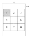
ここで、「図柄組合せラインL2」とは、演出用リール51L、51C、及び51Rの停止時における図柄の並びラインであって、図柄の組合せを形成させるラインである。図1に示すように、本実施形態では、水平方向の中段、上段及び下段にそれぞれ設けられた3つのラインと、右下がりの斜め方向のラインと、左下がりの斜め方向のラインとの合計5本のラインが、図柄組合せラインL2として設けられている。そして、各演出用リール51L、51C、及び51Rの上下に連続する3つ図柄は、それぞれ1つ以上の図柄組合せラインL2上に位置している。   Here, the “symbol combination line L2” is a line of symbols when the effect reels 51L, 51C, and 51R are stopped, and is a line that forms a combination of symbols. As shown in FIG. 1, in the present embodiment, a total of five lines including three lines respectively provided in the middle, upper and lower stages in the horizontal direction, a diagonal line in the lower right direction, and a diagonal line in the lower left direction. The book line is provided as a symbol combination line L2. Then, the three symbols that are continuous above and below each of the effect reels 51L, 51C, and 51R are positioned on one or more symbol combination lines L2.

このように、本実施形態では、第2表示窓12bから上下に連続する3つの図柄が見えるように、各演出用リール51L、51C、及び51Rを配置しているので、図柄組合せラインL2は、5本に設定されている。ただし、図柄組合せラインL2は5本に限定されない。例えば、第2表示窓12bから、上下に連続する4つの図柄が見えるように各遊技用リール51L、51C、及び51Rを配置した場合には、図柄組合せラインL2の数が増加することになる。このように、上下に連続する4つの図柄が見えるように、各演出用リール51L、51C、及び51Rを配置した場合には、水平方向における図柄組合せラインL2の数は、4本となる。さらに、右下がり及び左下がりの斜め方向の各図柄組合せラインL2は、それぞれ2本となる。よって、合計で8本の図柄組合せラインL2が形成されるようになる。   As described above, in the present embodiment, the effect reels 51L, 51C, and 51R are arranged so that three symbols that are continuous in the vertical direction can be seen from the second display window 12b. It is set to 5. However, the symbol combination line L2 is not limited to five. For example, when the game reels 51L, 51C, and 51R are arranged so that four symbols that are continuous in the vertical direction can be seen from the second display window 12b, the number of symbol combination lines L2 increases. In this manner, when the effect reels 51L, 51C, and 51R are arranged so that four symbols that are continuous in the vertical direction can be seen, the number of symbol combination lines L2 in the horizontal direction is four. In addition, there are two symbol combination lines L2 in the diagonal direction of right-down and left-down. Therefore, a total of eight symbol combination lines L2 are formed.

図1に示した5本の図柄組合せラインL2のうち、所定の図柄組合せラインL2が有効ラインに設定される。前述したように、本実施形態では、1回の遊技で遊技者によって投入されるメダルの枚数(賭数)は、一律3枚に設定されている。すなわち、メダルの投入枚数が、1枚又は2枚では遊技を行うことができないようにしている。そして、3枚のメダルの投入によって、全ての(5本の)図柄組合せラインL2を有効ラインに設定している。このときは、遊技用リールユニット30の図柄組合せラインL1も、役の入賞に係わるラインとして有効ラインに設定される。
ただし、投入されたメダルの枚数が1枚又は2枚のときでも、遊技を行うことが可能になるようにしても良い。この場合には、投入されたメダル枚数に応じて、複数の図柄組合せラインL2の中から、有効ラインと無効ラインとが設定される。
Of the five symbol combination lines L2 shown in FIG. 1, a predetermined symbol combination line L2 is set as an effective line. As described above, in the present embodiment, the number of medals (the number of bets) inserted by the player in one game is uniformly set to three. That is, the game cannot be played when the number of inserted medals is one or two. Then, by inserting three medals, all (five) symbol combination lines L2 are set as effective lines. At this time, the symbol combination line L1 of the gaming reel unit 30 is also set as an effective line as a line related to winning a winning combination.
However, even when the number of inserted medals is one or two, it may be possible to play a game. In this case, an effective line and an invalid line are set from the plurality of symbol combination lines L2 according to the number of inserted medals.

ここで、図柄組合せラインL2の有効ラインとは、演出用リール51L、51C、及び51Rの停止時に、遊技者に対して何らかの利益を付与する図柄の組合せであるか否かの判別対象となるラインである。
一方、図柄組合せラインL2の無効ラインとは、例えばメダルの投入枚数が1枚又は2枚のときに生じ、前記有効ラインとして設定されない図柄組合せラインであって、図柄の組合せの成立対象にならないラインをいう。
Here, the effective line of the symbol combination line L2 is a line that is a target of determination as to whether or not it is a symbol combination that gives some benefit to the player when the production reels 51L, 51C, and 51R are stopped. It is.
On the other hand, the invalid line of the symbol combination line L2 is, for example, a symbol combination line that is generated when the number of inserted medals is one or two and is not set as the effective line, and is a line that is not an object of symbol combination establishment. Say.

また、図柄組合せラインL2に対する有効ラインの数を、メダルの投入枚数に応じて変化させる場合には、例えば、以下のようにして有効ラインと無効ラインとを設定すればよい。   Further, when the number of valid lines for the symbol combination line L2 is changed according to the number of inserted medals, for example, the valid lines and invalid lines may be set as follows.

先ず、メダルの投入枚数が1枚であるときには、水平方向中段の図柄組合せラインL2(1本)を有効ラインに設定するとともに、残りの4本の図柄組合せラインL2を無効ラインに設定する。また、メダルの投入枚数が2枚であるときには、水平方向中段、上段及び下段の図柄組合せラインL2(合計3本)を有効ラインに設定するとともに、他の2本の図柄組合せラインL2を無効ラインに設定する。さらに、本実施形態のように、メダルの投入枚数が3枚であるときには、全ての図柄組合せラインL2(合計5本)を有効ラインに設定し、無効ラインは存在しないようにする。   First, when the number of inserted medals is 1, the horizontal symbol combination line L2 (one) is set as an effective line, and the remaining four symbol combination lines L2 are set as invalid lines. When the number of inserted medals is 2, the horizontal middle, upper and lower symbol combination lines L2 (three in total) are set as valid lines, and the other two symbol combination lines L2 are invalid lines. Set to. Further, as in the present embodiment, when the number of inserted medals is 3, all symbol combination lines L2 (total of 5) are set as valid lines so that there are no invalid lines.

(遊技用リールと演出用リールとの関係)
続いて、遊技用リール31L、31C、及び31Rと、演出用リール51L、51C、及び51Rとの関係について説明する。
(Relationship between game reels and production reels)
Next, the relationship between the game reels 31L, 31C, and 31R and the effect reels 51L, 51C, and 51R will be described.

本実施形態では、従来のスロットマシンにおいて通常の遊技用リールが配置されている位置に、演出用リール51L、51C、及び51Rを配置している。また、従来のスロットマシンにおいて液晶表示装置等の演出表示装置が配置されている、スロットマシン内の上方部に、遊技用リール31L、31C、及び31Rを配置している。   In the present embodiment, the production reels 51L, 51C, and 51R are arranged at positions where ordinary game reels are arranged in the conventional slot machine. In addition, game reels 31L, 31C, and 31R are arranged in an upper portion of the slot machine where an effect display device such as a liquid crystal display device is arranged in the conventional slot machine.

本実施形態の演出用リールユニット50の各演出用リール51L、51C、及び51Rは、その回転動作と、その停止動作と、最終的位置での各演出用リール51L、51C、及び51Rの図柄の組合せとのうち、少なくとも1つによって、演出を行うものである。また、遊技用リールユニット30の各遊技用リール31L、31C、及び31Rは、従来の一般的なスロットマシンに設けられているリールと同等の機能を果たすものであり、停止時の各遊技用リール31L、31C、及び31Rの図柄の組合せにより、遊技の結果を表示するものである。   Each of the effect reels 51L, 51C, and 51R of the effect reel unit 50 according to the present embodiment has the rotation operation, the stop operation, and the symbols of the effect reels 51L, 51C, and 51R at the final position. Production is performed by at least one of the combinations. Each of the gaming reels 31L, 31C, and 31R of the gaming reel unit 30 performs the same function as a reel provided in a conventional general slot machine, and each gaming reel at the time of stopping. The game result is displayed by a combination of symbols 31L, 31C, and 31R.

本実施形態の遊技用リール31L、31C、及び31Rは、演出用リール51L、51C、及び51Rよりも小さく形成されている。すなわち、各遊技用リール31L、31C、及び31Rの直径をL、各演出用リール51L、51C、及び51Rの直径をL´としたとき、
L'>L
としている。
The game reels 31L, 31C, and 31R of the present embodiment are formed smaller than the effect reels 51L, 51C, and 51R. That is, when the diameter of each gaming reel 31L, 31C, and 31R is L and the diameter of each effect reel 51L, 51C, and 51R is L ′,
L '> L
It is said.

本実施形態では、遊技用リール31L、31C、及び31Rの直径を約120mm、横幅を約44.5mmとした。これに対し、演出用リール51L、51C、及び51Rの直径を約230mm、横幅を約80mmとした。すなわち、遊技用リール31L、及び31C、31Rの直径及び横幅の双方が、それぞれ演出用リール51L、51C、及び51Rの直径及び横幅よりも小さく形成されるようにした。これに伴い、第1表示窓12aの領域は、第2表示窓12bの領域よりも小さく形成される。   In this embodiment, the diameter of the game reels 31L, 31C, and 31R is about 120 mm, and the lateral width is about 44.5 mm. On the other hand, the diameters of the production reels 51L, 51C, and 51R are about 230 mm, and the width is about 80 mm. In other words, both the diameter and width of the game reels 31L, 31C, and 31R are formed smaller than the diameter and width of the effect reels 51L, 51C, and 51R, respectively. Accordingly, the area of the first display window 12a is formed smaller than the area of the second display window 12b.

従来のスロットマシンでは、演出表示装置の表示領域は、遊技の結果を表示するリール上の図柄の表示領域よりも小さいのが普通である。これは、スロットマシンでの遊技の結果は、本実施形態の遊技用リール31L、31C、及び31Rに相当するリールが停止したときの図柄の組合せにより決定されるのであって、演出表示装置の表示内容によって決定されるものではないからである。すなわち、演出表示装置は、遊技の結果が決定するまで(少なくとも1つのリールの回転中)、あるいは遊技の結果が決定した後(全てのリールの停止後)に、役が当選する可能性がどの程度あるのか等を報知する装置であり、遊技の進行において補助的な役割を有する装置だからである。   In the conventional slot machine, the display area of the effect display device is usually smaller than the display area of the symbols on the reel displaying the game result. This is because the result of the game in the slot machine is determined by the combination of symbols when the reels corresponding to the game reels 31L, 31C, and 31R of the present embodiment are stopped, and the display of the effect display device This is because it is not determined by the content. In other words, the effect display device determines the possibility that a winning combination will be won until the game result is determined (at least one reel is rotating) or after the game result is determined (after all reels are stopped). This is because it is a device for informing whether there is a degree, etc., and is a device having an auxiliary role in the progress of the game.

これに対し、本実施形態では、遊技用リール31L、31C、及び31Rと、演出用リール51L、51C、及び51Rとの大きさの関係、及び第1表示窓12aと、第2表示窓12bとの大きさの関係を前述のようにする。さらに、図1に示したように、前面側から見て、操作スイッチ40の上部に演出用リールユニット50(第2表示窓12b)を配置し、演出用リールユニット50から操作スイッチ40に対して遠ざかる側に遊技用リールユニット30(第1表示窓12a)を配置している。
言い換えれば、前面側から見て、遊技用リールユニット30(第1表示窓12a)と、操作スイッチ40との間に、演出用リールユニット50(第2表示窓12b)を配置している。
On the other hand, in this embodiment, the relationship between the size of the game reels 31L, 31C, and 31R and the effect reels 51L, 51C, and 51R, the first display window 12a, and the second display window 12b The relationship of the size of is as described above. Further, as shown in FIG. 1, when viewed from the front side, an effect reel unit 50 (second display window 12 b) is disposed above the operation switch 40, and the effect reel unit 50 extends to the operation switch 40. A gaming reel unit 30 (first display window 12a) is arranged on the side away from the player.
In other words, when viewed from the front side, the effect reel unit 50 (second display window 12b) is arranged between the game reel unit 30 (first display window 12a) and the operation switch 40.

このような構成とすることにより、前面側から見て、スロットマシン10の略中央に、すなわち、遊技者が遊技を行っているときに最も見やすく、且つ遊技用リール31L、31C、及び31Rよりも視界に入りやすい位置にある演出用リール51L、51C、及び51Rを、演出のためのリールにすることできる。これにより、リールの停止状況を見ながら遊技が進行することを維持しつつ、演出が中心となって遊技を進行させることができる。   By adopting such a configuration, when viewed from the front side, it is most easily seen at the approximate center of the slot machine 10, that is, when the player is playing a game, and more than the gaming reels 31L, 31C, and 31R. The production reels 51L, 51C, and 51R at positions that are easy to enter the field of view can be used as production reels. Thereby, it is possible to advance the game mainly in the production while maintaining the progress of the game while watching the reel stop state.

詳細は後述するが、スロットマシン10の略中央にあるリールを、演出のための演出用リール51L、51C、及び51Rにすることによって、遊技の結果を表示するための従来のリールでは実現することができなかった多種多様な動きを、遊技者にとって見易い位置にあるリールに行わせることができる。   As will be described in detail later, the reel at the approximate center of the slot machine 10 is made to be an effect reel 51L, 51C, and 51R for effect, which is realized with a conventional reel for displaying game results. A variety of movements that could not be performed can be performed on the reel in a position that is easy to see for the player.

本実施形態では、遊技用リール31L、31C、及び31Rの直径をL、演出用リール51L、51C、及び51Rの直径をL´としたときに、
L≧L'/2
を満たすようにした。
In the present embodiment, when the game reels 31L, 31C, and 31R have a diameter L and the effect reels 51L, 51C, and 51R have a diameter L ′,
L ≧ L ′ / 2
It was made to satisfy.

また、遊技用リール31L、31C、及び31Rの直径Lの大きさと、演出用リール51L、51C、及び51Rの直径L´の大きさとの関係と、後述する遊技用リール31L、31C、及び31Rの停止制御と、演出用リール51L、51C、及び51Rの停止制御とを考慮して、遊技用リール31L、31C、及び31Rの図柄数Nと、演出用リール51L、51C、及び51Rの図柄数N´との関係を、
N´>N>N´/2
とした。
Further, the relationship between the size of the diameter L of the game reels 31L, 31C, and 31R and the size of the diameter L ′ of the effect reels 51L, 51C, and 51R, and the game reels 31L, 31C, and 31R described later. Considering stop control and stop control of effect reels 51L, 51C, and 51R, the number of symbols N of game reels 31L, 31C, and 31R and the number of symbols N of effect reels 51L, 51C, and 51R The relationship with ´
N '>N>N' / 2
It was.

さらに、本実施形態では、遊技用リール31L、31C、及び31Rの図柄の配列ピッチ(=(L×π)/N)と、演出用リール51L、51C、及び51Rの図柄の配列ピッチ(=(L´×π)/N´)との関係を、
(L×π)/N≦(L´×π)/N´
とした。
Further, in the present embodiment, the symbol arrangement pitch (= (L × π) / N) of the game reels 31L, 31C, and 31R and the symbol arrangement pitch of the effect reels 51L, 51C, and 51R (= ( L ′ × π) / N ′)
(L × π) / N ≦ (L ′ × π) / N ′
It was.

ここで、演出用リール51L、51C、及び51Rの図柄数N´を21個に設定した場合に、N/N´の値がL/L´の値に最も近くなるようにNを決定すれば、遊技用リール31L、31C、及び31Rの図柄数Nは、11個となる。しかし、本実施形態では、遊技用リール31L、31C、及び31Rの図柄の配列間隔を、演出用リール51L、51C、及び51Rの図柄の配列間隔よりやや狭めとし、且つ前記図柄の配列間隔が適当な値となるように、遊技用リール31L、31C、及び31Rの図柄数Nを13個とした。   Here, when the number of symbols N ′ for the production reels 51L, 51C, and 51R is set to 21, N is determined so that the value of N / N ′ is closest to the value of L / L ′. The number of symbols N of the game reels 31L, 31C, and 31R is 11. However, in this embodiment, the symbol arrangement interval of the game reels 31L, 31C, and 31R is slightly narrower than the symbol arrangement interval of the effect reels 51L, 51C, and 51R, and the symbol arrangement interval is appropriate. The number of symbols N of the game reels 31L, 31C, and 31R was set to 13 so as to be a reasonable value.

これにより、遊技者による遊技用リール31L、31C、及び31R上の図柄と、演出用リール51L、51C、及び51R上の図柄との視認性を確保しつつ、遊技用リール31L、31C、及び31Rに表示可能な図柄数と、演出用リール51L、51C、及び51Rに表示可能な図柄数とのバランスをとることができる。   Thereby, the game reels 31L, 31C, and 31R are secured while ensuring the visibility of the symbols on the game reels 31L, 31C, and 31R and the symbols on the effect reels 51L, 51C, and 51R. The number of symbols that can be displayed on the screen and the number of symbols that can be displayed on the effect reels 51L, 51C, and 51R can be balanced.

特に、遊技用リール31L、31C、及び31Rの図柄が必要以上に小さくなってしまうと、遊技用リール31L、31C、及び31Rの回転中の図柄の識別性が劣ることとなる。遊技者にとって視認性を良くするために、図柄の大きさは、縦25mm以上、横35mm以上であることが好ましい。そこで、本実施形態では、遊技用リール31L、31C、及び31Rの横幅を、前述のように約45mmとすることで、1つの図柄が表示される領域における横の長さを35mm以上確保できるようにした。さらに、遊技用リール31L、31C、及び31Rの直径Lを約120mmにし、かつ遊技用リール31L、31C、及び31Rの図柄数Nを13個にすることで、1つの図柄が表示される領域における縦の長さを25mm以上確保できるようにした。   In particular, if the symbols of the game reels 31L, 31C, and 31R become smaller than necessary, the distinctiveness of the symbols during rotation of the game reels 31L, 31C, and 31R will be poor. In order to improve the visibility for the player, the size of the pattern is preferably 25 mm or more in length and 35 mm or more in width. Therefore, in this embodiment, the horizontal width of the gaming reels 31L, 31C, and 31R is set to about 45 mm as described above so that the horizontal length in the area where one symbol is displayed can be secured to 35 mm or more. I made it. Further, by setting the diameter L of the gaming reels 31L, 31C, and 31R to about 120 mm and the number of symbols N of the gaming reels 31L, 31C, and 31R to 13 in the area where one symbol is displayed. The vertical length can be secured at 25 mm or more.

このように、遊技用リール31L、31C、及び31Rの図柄数Nを13個、遊技用リール31L、31C、及び31Rの直径Lを120mmとした場合、前記図柄の配列間隔PPは、
PP=(120×3.14)/13=29mm
となる。
Thus, when the number of symbols N of the game reels 31L, 31C, and 31R is 13, and the diameter L of the game reels 31L, 31C, and 31R is 120 mm, the symbol arrangement interval PP is:
PP = (120 × 3.14) / 13 = 29 mm
It becomes.

また、遊技用リール31L、31C、及び31Rの直径L及び図柄数Nと、演出用リール51L、51C、及び51Rの直径L´及図柄数N´との関係に見合うように、遊技用リール31L、31C、及び31Rの外部(第1表示窓12a)から透視できる図柄数Rと、演出用リール51L、51C、及び51Rの外部(第2表示窓12b)から視認できる図柄数R´との関係、及び遊技用リール31L、31C、及び31Rにおける図柄組合せラインL1の数Pと、演出用リール51L、51C、及び51Rにおける図柄組合せラインL2の数P´との関係を、それぞれ、
R<R´
及び
P<P´
とした。
Also, the gaming reels 31L, 31C, and 31R have a diameter L and a number N of symbols, and the reels 31L, 51C, and 51R have a diameter L ′ and a number of symbols N ′ that match the relationship between the diameter L ′ and the number of symbols N ′. , 31C and 31R between the number of symbols R that can be seen through from the first display window 12a and the number of symbols R ′ that can be seen from the outside of the production reels 51L, 51C, and 51R (second display window 12b) , And the number P of the symbol combination lines L1 on the game reels 31L, 31C, and 31R and the number P ′ of the symbol combination lines L2 on the effect reels 51L, 51C, and 51R, respectively,
R <R '
And P <P '
It was.

演出用リール51L、51C、及び51Rの外部から視認できる図柄数R´は3個であるのに対し、遊技用リール31L、31C、及び31Rの外部から視認できる図柄数Rは1個である。
また、演出用リール51L、51C、及び51Rにおける図柄組合せラインL2の数P´は5本であるのに対し、遊技用リール31L、31C、及び31Rにおける図柄組合せラインL1の数Pは1本である。
The number of symbols R ′ visible from the outside of the effect reels 51L, 51C, and 51R is three, whereas the number of symbols R visible from the outside of the game reels 31L, 31C, and 31R is one.
Further, the number P ′ of the symbol combination lines L2 on the effect reels 51L, 51C, and 51R is five, whereas the number P of the symbol combination lines L1 on the game reels 31L, 31C, and 31R is one. is there.

ただし、前述したように、R=1、P=1以外にし、各遊技用リール31L、31C、及び31Rの連続する2つの図柄が、第1表示窓12aから視認できるようにし、水平方向の2本を図柄組合せラインL1に設定することも可能である。すなわち、R=2、P=2に設定することも可能である。   However, as described above, except for R = 1 and P = 1, two consecutive symbols of each of the game reels 31L, 31C, and 31R can be visually recognized from the first display window 12a, and 2 in the horizontal direction. It is also possible to set the book to the symbol combination line L1. That is, it is possible to set R = 2 and P = 2.

ところで、遊技用リール31L、31C、及び31Rの図柄数Nと、演出用リール51L、51C、及び51Rの図柄数N´との関係を前述のように設定したのは、ストップスイッチ42L、42C、及び42Rが操作されたときから、遊技用リール31L、31C、及び31Rと、演出用リール51L、51C、及び51Rとが停止するまでの、遊技用リール31L、31C、及び31Rと、演出用リール51L、51C、及び51Rとの最大移動回転角度をほぼ一定にするためである。このようにすることで、遊技用リール31L、31C、及び31Rと、演出用リール51L、51C、及び51Rとを、遊技者に違和感を与えることなく停止させることができるとともに、遊技用リール31L、31C、及び31Rと、演出用リール51L、51C、及び51Rとの停止制御により、有効ライン上に停止させるべき図柄の組合せに、ある程度の幅を持たせることができる。   By the way, the relationship between the number of symbols N of the game reels 31L, 31C, and 31R and the number of symbols N ′ of the effect reels 51L, 51C, and 51R is set as described above. The stop switches 42L, 42C, And the reels 31L, 31C, and 31R, and the effect reels until the game reels 31L, 31C, and 31R and the effect reels 51L, 51C, and 51R stop. This is to make the maximum movement rotation angle with 51L, 51C, and 51R substantially constant. In this way, the gaming reels 31L, 31C, and 31R and the production reels 51L, 51C, and 51R can be stopped without giving the player a sense of incongruity, and the gaming reels 31L, 31L, The combination of symbols to be stopped on the effective line can be given a certain width by stop control of the 31C and 31R and the production reels 51L, 51C, and 51R.

ここで、遊技用リール31L、31C、及び31Rに相当する従来のリールでは、役の当選時に、遊技者がその当選役に対応する図柄の組合せを有効ラインに比較的容易に停止させることができるようにするため、ストップスイッチが操作されてから実際にリールが停止するまで、一定数の図柄を移動可能にしている。一方、ストップスイッチの操作後に、リールが不自然に停止しないように、ストップスイッチのオンを検知したときから、リールが停止するまでの時間は、通常、190ms以下に設定されている。また、リールの回転時には、リール上の図柄を遊技者がおおむね識別できるようにするため、リールの回転速度は、1分間に80回転を超えないように設定されている。   Here, in the conventional reels corresponding to the gaming reels 31L, 31C, and 31R, when the winning combination is won, the player can relatively easily stop the combination of symbols corresponding to the winning combination on the effective line. Therefore, a certain number of symbols can be moved from when the stop switch is operated until the reel actually stops. On the other hand, after the stop switch is operated, the time from when the stop switch is turned on until the reel stops is usually set to 190 ms or less so that the reel does not stop unnaturally. Further, when the reel rotates, the reel rotation speed is set so as not to exceed 80 rotations per minute so that the player can generally identify the symbols on the reel.

以上のことを考慮して、従来では、リール上の図柄を21個とした場合、ストップスイッチのオンを検知してからリールが停止するまでの最大移動図柄数は、ストップスイッチのオンを検知した瞬間に位置する図柄を含めて5図柄に設定されている。
そして、このような従来のリールの動作に鑑みて、本実施形態においては、演出用リール51L、51C、及び51Rの最大移動図柄数を、原則として5図柄に設定している。
Considering the above, when the number of symbols on the reel is 21 in the past, the maximum number of symbols to be moved from when the stop switch is turned on until the reel stops is detected as the stop switch being turned on. It is set to 5 symbols including the symbols located at the moment.
In view of the operation of such a conventional reel, in the present embodiment, the maximum number of moving symbols of the effect reels 51L, 51C, and 51R is set to 5 symbols in principle.

また、遊技用リール31L、31C、及び31Rの回転速度と停止制御とを、演出用リール51L、51C、及び51Rに準じるようにするための、遊技用リール31L、31C、及び31Rの最大移動図柄数Kと、演出用リール51L、51C、及び51Rの最大移動図柄数をK´との関係は、遊技用リール31L、31C、及び31Rの図柄数Nと、演出用リール51L、51C、及び51Rの図柄数N´との関係より、
K<K´
に設定される。
特に、本実施形態では、
K≧K´/2
に設定している。
In addition, the maximum movement pattern of the game reels 31L, 31C, and 31R in order to make the rotation speed and stop control of the game reels 31L, 31C, and 31R conform to the production reels 51L, 51C, and 51R. The relationship between the number K and the maximum moving symbol number K ′ of the effect reels 51L, 51C, and 51R is as follows: the symbol number N of the game reels 31L, 31C, and 31R and the effect reels 51L, 51C, and 51R From the relationship with the number of symbols N '
K <K '
Set to
In particular, in this embodiment,
K ≧ K ′ / 2
Is set.

さらに、遊技用リール31L、31C、及び31Rの最大移動図柄数Kを、
(N×K´)/N´
以下の整数の最大値に設定している。
すなわち、遊技用リール31L、31C、及び31Rの図柄数Nを13個、演出用リール51L、51C、及び51Rの図柄数N´を21個とし、かつ演出用リール51L、51C、及び51Rの最大移動図柄数K´を5個としたとき、遊技用リール31L、31C、及び31Rの最大移動速度Kは、
K=13×5/21≒3.095
となる。
よって、3.095以下の整数の最大値は3であるので、遊技用リール31L、31C、及び31Rの最大移動図柄数Kを3図柄とした。
Furthermore, the maximum movement symbol number K of the game reels 31L, 31C, and 31R is
(N x K ') / N'
The maximum value of the following integers is set.
That is, the number of symbols N of the game reels 31L, 31C, and 31R is 13, the number of symbols N ′ of the effect reels 51L, 51C, and 51R is 21, and the maximum of the effect reels 51L, 51C, and 51R When the number of moving symbols K ′ is 5, the maximum moving speed K of the gaming reels 31L, 31C, and 31R is
K = 13 × 5/21 ≒ 3.095
It becomes.
Therefore, since the maximum value of the integer less than or equal to 3.095 is 3, the maximum moving symbol number K of the game reels 31L, 31C, and 31R is set to 3 symbols.

なお、遊技用リール31L、31C、及び31Rの図柄数Nが少なすぎると、それに応じて停止時の最大移動図柄数Kが少なくなる。例えば、前述したように、(N/N´)の値が(L/L´)の値に最も近くなるように、遊技用リール31L、31C、及び31Rの図柄数Nを決定すれば、遊技用リール31L、31C、及び31Rの図柄数Nは11個である。しかしながら、この場合には、最大移動図柄数Kが2図柄となってしまう。これにより、遊技用リール31L、31C、及び31Rの停止時における図柄の組合せ総数、あるいは遊技用リール31L、31C、及び31Rの図柄配列が制約を受けやすくなる。   Note that if the number of symbols N of the game reels 31L, 31C, and 31R is too small, the maximum number K of moving symbols at the time of stopping decreases accordingly. For example, as described above, if the number of symbols N of the game reels 31L, 31C, and 31R is determined so that the value of (N / N ′) is closest to the value of (L / L ′), the game The number of symbols N for the reels 31L, 31C, and 31R is eleven. However, in this case, the maximum moving symbol number K is 2 symbols. As a result, the total number of symbol combinations when the gaming reels 31L, 31C, and 31R are stopped, or the symbol arrangement of the gaming reels 31L, 31C, and 31R is likely to be restricted.

このため、本実施形態では、前述のように、遊技用リール31L、31C、及び31Rの図柄配列間隔を、演出用リール51L、51C、及び51Rの図柄配列間隔よりやや狭めとし、
N>N'/2
の関係が成り立つようにする。これにより、遊技用リール31L、31C、及び31Rを小さく形成しつつも、演出用リール51L、51C、及び51Rに準じた停止制御を行ったときの、遊技用リール31L、31C、及び31Rの最大移動図柄数を十分に確保することができる。本実施形態では、遊技用リール31L、31C、及び31Rの図柄数Nを13個とすることで、遊技用リール31L、31C、及び31Rの停止制御を、演出用リール51L、51C、及び51Rに準じるようにし、且つ遊技用リール31L、31C、及び31Rの最大移動図柄数Kが3図柄となるようにした。
Therefore, in this embodiment, as described above, the symbol arrangement interval of the game reels 31L, 31C, and 31R is slightly narrower than the symbol arrangement interval of the effect reels 51L, 51C, and 51R.
N> N '/ 2
The relationship is established. Accordingly, the maximum of the game reels 31L, 31C, and 31R when the stop control according to the effect reels 51L, 51C, and 51R is performed while the game reels 31L, 31C, and 31R are formed to be small. A sufficient number of moving symbols can be secured. In the present embodiment, the number of symbols N of the game reels 31L, 31C, and 31R is set to 13, so that the stop control of the game reels 31L, 31C, and 31R is controlled to the effect reels 51L, 51C, and 51R. In addition, the maximum movement symbol number K of the game reels 31L, 31C, and 31R is set to 3 symbols.

図5において、例えば左の遊技用リール31Lの図柄に着目すると、1番上から順に、「スイカ」、「ふどう」、及び「レモン」の図柄が配列されているが、3番目の「レモン」の位置が有効ライン上に位置する瞬間にストップスイッチ42Lが操作されると、この「レモン」の他に、その上の「ぶどう」、及びさらにその上の「スイカ」を有効ラインに停止させることができる。   In FIG. 5, for example, paying attention to the design of the left game reel 31L, the symbols “watermelon”, “fudo”, and “lemon” are arranged in order from the top, but the third “lemon” When the stop switch 42L is operated at the moment when the position of "" is on the active line, in addition to this "lemon", the "grape" above it and the "watermelon" above it are stopped at the active line. be able to.

そして、図5に示した例では、左の遊技用リール31Lについては、「スイカ」及び「ぶどう」は、3図柄以内の間隔で配置されている。これにより、遊技用リール31Lについては、どの位置でストップスイッチ42Lが操作されても、「スイカ」及び「ぶどう」を有効ラインに停止させることが可能となる。   In the example shown in FIG. 5, “watermelon” and “grape” are arranged at intervals within 3 symbols for the left gaming reel 31L. As a result, regarding the gaming reel 31L, it becomes possible to stop the “watermelon” and “grape” on the active line regardless of the position of the stop switch 42L.

また、中央の遊技用リール31Cの「桃(例えば、1番上の図柄)」及び「ぶどう(例えば、上から2番目の図柄)」についても同様に、3図柄以内の間隔で配列されている。さらに、右の遊技用リール31Rの「桃(例えば、1番上の図柄)」及び「レモン(例えば、上から2番目の図柄)」についても同様に、3図柄以内の間隔で配列されている。   Similarly, the “peach (for example, the top symbol)” and “grape (for example, the second symbol from the top)” of the central gaming reel 31C are also arranged at intervals within three symbols. . Further, “peach (for example, the top symbol)” and “lemon (for example, the second symbol from the top)” of the right game reel 31R are similarly arranged at intervals within three symbols. .

したがって、「スイカ/ぶどう」−「桃/ぶどう」−「桃/レモン」の図柄の組合せ(全部で8通り)に対応させた役については、どの位置でストップスイッチ42L、42C、及び42Rが操作されても、常に、有効ラインに停止させることができる。言い換えれば、遊技用リール31L、31C、及び31Rの停止制御によって、前記図柄の組合せに対応する役を常に入賞させることができる。   Therefore, the stop switches 42L, 42C, and 42R are operated at any position for the combination corresponding to the combination of symbols of “watermelon / grape”-“peach / grape”-“peach / lemon” (8 ways in total). However, it is always possible to stop at the active line. In other words, the combination corresponding to the combination of symbols can be always won by the stop control of the gaming reels 31L, 31C, and 31R.

また、本実施形態では、遊技用リール31L、31C、及び31Rの回転速度が約78.13rpm(1周時間が約768ms)、演出用リール51L、51C、及び51Rの回転速度が約79.87rpm(1周時間が約751ms)となるように、各リールの回転速度を制御している。   In the present embodiment, the rotation speeds of the game reels 31L, 31C, and 31R are about 78.13 rpm (one lap time is about 768 ms), and the rotation speeds of the production reels 51L, 51C, and 51R are about 79.87 rpm. The rotation speed of each reel is controlled so that (one round time is about 751 ms).

具体的には、遊技用リール31L、31C、及び31Rを回転させるためのステッピングモータ32L、32C、及び32R(図12を参照)の1回転あたりのステップ数と、演出用リール51L、51C、及び51Rを回転させるためのステッピングモータ52L、52C、及び52R(図13を参照)の1回転あたりのステップ数とを、ともに400としている。   Specifically, the number of steps per rotation of the stepping motors 32L, 32C, and 32R (see FIG. 12) for rotating the gaming reels 31L, 31C, and 31R, and the effect reels 51L, 51C, and The number of steps per rotation of stepping motors 52L, 52C, and 52R (see FIG. 13) for rotating 51R is 400.

さらに、本実施形態では、ステッピングモータ32L、32C、及び32Rにおける、1ステップ当たりの回転駆動時間(割込み時間)を約1.92msにしている。これにより、ステッピングモータ32L、32C、及び32Rが1回転するのに要する時間を、(1.92ms×400ステップ=)約768msにすることができる。一方、ステッピングモータ52L、52C、及び52Rにおける、1ステップ当たりの回転駆動時間(割込み時間)を約1.878msにしている。これにより、ステッピングモータ52L、52C、及び52Rが1回転するのに要する時間を、(1,878ms×400ステップ=)約751msにすることができる。   Furthermore, in this embodiment, the rotation driving time (interrupt time) per step in the stepping motors 32L, 32C, and 32R is set to about 1.92 ms. As a result, the time required for one rotation of the stepping motors 32L, 32C, and 32R can be reduced to about 768 ms (1.92 ms × 400 steps =). On the other hand, the rotation driving time (interruption time) per step in the stepping motors 52L, 52C, and 52R is set to about 1.878 ms. As a result, the time required for one rotation of the stepping motors 52L, 52C, and 52R can be reduced to about 751 ms (1,878 ms × 400 steps =).

このようにすることで、遊技用リール31L、31C、及び31Rの回転速度と、演出用リール51L、51C、及び51Rの回転速度とは、近似するが同一ではない、すなわち同期していないこととなる。よって、演出用リール51L、51C、及び51Rを遊技用リール31L、31C、及び31Rの目押し補助として用いることができないようにすることができる。すなわち、演出用リール51L、51C、及び51Rの回転中の特定の図柄を識別することによって、遊技用リール31L、31C、及び31Rの特定の図柄を目押しする(特定の図柄が停止するように狙う)ことができないようにすることができる。   By doing so, the rotational speeds of the gaming reels 31L, 31C, and 31R and the rotational speeds of the effect reels 51L, 51C, and 51R are approximate but not the same, that is, not synchronized. Become. Therefore, it is possible to prevent the effect reels 51L, 51C, and 51R from being used as auxiliary pushes for the game reels 31L, 31C, and 31R. That is, by identifying specific symbols during rotation of the production reels 51L, 51C, and 51R, the specific symbols of the game reels 31L, 31C, and 31R are aimed at (so that the specific symbols are stopped). Can not be aimed).

なお、遊技用リール31L、31C、及び31Rの回転速度と、演出用リール51L、51C、及び51Rの回転速度とが同期しないようにする場合には、遊技用リール31L、31C、及び31Rが最大回転速度に達したときの回転速度と、演出用リール51L、51C、及び51Rが最大回転速度に達したときの回転速度とが同期しないようにすれば良い。   When the rotation speeds of the game reels 31L, 31C, and 31R and the rotation speeds of the effect reels 51L, 51C, and 51R are not synchronized, the game reels 31L, 31C, and 31R are the maximum. The rotation speed when the rotation speed is reached may not be synchronized with the rotation speed when the effect reels 51L, 51C, and 51R reach the maximum rotation speed.

例えば、遊技用リール31L、31C、及び31Rの回転開始時から最大回転速度(等速度)に達するまでの加速域と、演出用リール51L、51C、及び51Rの回転開始時から最大回転速度(等速度)に達するまでの加速域とにおいて、遊技用リール31L、31C、及び31Rの回転速度と、演出用リール51L、51C、及び51Rの回転速度とが一致する瞬間が存在したとしても、通常は、役の入賞に直接関係する遊技用リール31L、31C、及び31Rの加速域では、ストップスイッチ42L、42C、及び42Rを有効にしないようにし、遊技用リール31L、31C、及び31Rが等速度に達した後にストップスイッチ42L、42C、及び42Rの操作が有効になるようにしている。したがって、遊技用リール31L、31C、及び31Rの回転速度と、演出用リール51L、51C、及び51Rの回転速度とがともに等速度である最大回転速度に達したときに、両者の回転速度が同期しないように制御すれば、演出用リール51L、51C、及び51Rを遊技用リール31L、31C、及び31Rの目押し補助として用いることができないようにすることができる。   For example, the acceleration range from the start of rotation of the gaming reels 31L, 31C, and 31R to the maximum rotational speed (equal speed) and the maximum rotational speed (etc. from the start of rotation of the effect reels 51L, 51C, and 51R) Even if there is a moment when the rotation speed of the gaming reels 31L, 31C, and 31R and the rotation speed of the effect reels 51L, 51C, and 51R coincide with each other in the acceleration range until reaching the speed) In the acceleration range of the gaming reels 31L, 31C, and 31R, which are directly related to the winning of the winning combination, the stop switches 42L, 42C, and 42R are not made effective, and the gaming reels 31L, 31C, and 31R are kept at the same speed. The operation of the stop switches 42L, 42C, and 42R is made effective after the time is reached. Accordingly, when the rotation speeds of the game reels 31L, 31C, and 31R and the rotation speeds of the effect reels 51L, 51C, and 51R reach the maximum rotation speed that is the same speed, the rotation speeds of both are synchronized. If it controls so that it does not, it can be made not to be able to use the reels 51L, 51C, and 51R for play as the auxiliary for pushing the game reels 31L, 31C, and 31R.

(通常遊技時のスロットマシンの概略動作)
次に、スロットマシン10における通常遊技について説明する。
通常遊技では、遊技者が、メダル投入口43から3枚のメダルを投入するか、ベットスイッチ45を操作すると、第1の表示窓12aにおける図柄組合せラインL1及び第2の表示窓12bにおける図柄組合せラインL2の全てのラインが有効ラインとして設定される。その後、遊技者がスタートレバー41を操作すると、遊技用リール31L、31C、及び31Rが全て回転し始める。
(General operation of slot machine during normal game)
Next, a normal game in the slot machine 10 will be described.
In the normal game, when the player inserts three medals from the medal insertion slot 43 or operates the bet switch 45, the symbol combination line L1 in the first display window 12a and the symbol combination in the second display window 12b. All lines of the line L2 are set as effective lines. Thereafter, when the player operates the start lever 41, the gaming reels 31L, 31C, and 31R all start to rotate.

続いて、遊技者がストップスイッチ42L、42C、及び42Rを操作すると、操作されたストップスイッチ42L、42C、及び42Rに対応する遊技用リール31L、31C、及び31Rの回転が停止する、そして、ストップスイッチ42L、42C、及び42Rの全てが操作され、遊技用リール31L、31C、及び31Rの全てが停止した際、有効ライン上に並んだ遊技用リール31L、31C、及び31Rの図柄の組合せが、予め定められた何らかの役の図柄の組合せと一致するときは入賞となり、その入賞役に応じてメダルの払い出しや再遊技等が行われる。   Subsequently, when the player operates the stop switches 42L, 42C, and 42R, the rotation of the gaming reels 31L, 31C, and 31R corresponding to the operated stop switches 42L, 42C, and 42R stops, and the stop When all of the switches 42L, 42C, and 42R are operated and all of the game reels 31L, 31C, and 31R are stopped, the combination of symbols of the game reels 31L, 31C, and 31R arranged on the active line is When it matches with a predetermined combination of symbols of a combination, a prize is awarded, and medals are paid out or replayed according to the winning combination.

ここで、本実施形態においては、3枚のメダルが投入された後、又はベットスイッチ45が操作された後に、スタートレバー41が操作されると、原則として、遊技用リール31L、31C、及び31Rとともに演出用リール51L、51C、及び51Rの全てが回転し始める。その後、各ストップスイッチ42L、42C、及び42Rが操作されると、その操作されたストップスイッチ42L、42C、及び42Rに対応する、遊技用リール31L、31C、及び31Rの回転と演出用リール51L、51C、及び51Rの回転とが停止する。例えば、ストップスイッチ42Lが操作されると、遊技用リール31Lと演出用リール51Lの回転が停止する。   Here, in this embodiment, when the start lever 41 is operated after three medals are inserted or after the bet switch 45 is operated, in principle, the gaming reels 31L, 31C, and 31R are operated. At the same time, all of the effect reels 51L, 51C, and 51R start to rotate. Thereafter, when each of the stop switches 42L, 42C, and 42R is operated, the rotation of the game reels 31L, 31C, and 31R corresponding to the operated stop switches 42L, 42C, and 42R and the effect reels 51L, The rotation of 51C and 51R stops. For example, when the stop switch 42L is operated, the rotation of the game reel 31L and the effect reel 51L stops.

なお、各演出用リール51L、51C、及び51Rの動きは、対応する各遊技用リール31L、31C、及び31Rに必ずしも連動しているわけではなく、後述する様々な演出に応じて任意である。   Note that the movements of the respective effect reels 51L, 51C, and 51R are not necessarily linked to the corresponding game reels 31L, 31C, and 31R, but are arbitrary according to various effects described later.

本実施形態のスロットマシンには、以上のような機能の他に、本実施形態の特徴である、「スタートレバーを用いて遊技者に演出を選択させる機能」、「遊技者に選択された演出を実行する機能」、及び「演出のデモンストレーションを行う機能」などを有している。以下に、これら本実施形態の特徴部分について説明する。   In the slot machine of this embodiment, in addition to the functions as described above, the features of this embodiment are “a function that allows the player to select an effect using the start lever”, “an effect selected by the player” "Function to execute" and "function to perform demonstration". Below, the characteristic part of this embodiment is demonstrated.

(遊技者選択系演出時のスロットマシンの概略動作)
次に、図7のタイミングチャートを参照しながら、遊技者が選択した演出を実行する際のスロットマシンの概略動作の一例を説明する。図7に示すタイミングチャートでは、図面に向かって左から右の方へ時間が経過する。なお、以下の説明においては、遊技者の選択に応じて行われる演出を「遊技者選択系演出」と称する。
(Schematic operation of the slot machine at the time of player selection system production)
Next, an example of a schematic operation of the slot machine when performing the effect selected by the player will be described with reference to the timing chart of FIG. In the timing chart shown in FIG. 7, time elapses from left to right as viewed in the drawing. In the following description, an effect performed in response to the player's selection is referred to as a “player selection system effect”.

まず、メダル投入口43に3枚のメダルが投入されるか、又はベットスイッチ45が操作されることにより3枚のメダルが投入されると、演出選択用画像を液晶表示装置13に表示する。図8は、液晶表示装置13に表示される演出選択用画像の一例を示す図である。
図8に示す演出選択用画像13aのように、本実施形態では、変位検出部の数と同数の、4つの演出の中から1つの演出を選択することができるようにしている。以下に、これら4つの演出の具体例を説明する。
First, when three medals are inserted into the medal insertion slot 43 or when three medals are inserted by operating the bet switch 45, an effect selection image is displayed on the liquid crystal display device 13. FIG. 8 is a diagram illustrating an example of an effect selection image displayed on the liquid crystal display device 13.
As in the effect selection image 13a shown in FIG. 8, in this embodiment, one effect can be selected from the four effects, which is the same as the number of displacement detection units. Hereinafter, specific examples of these four effects will be described.

(1) 逆回転演出
図9(a)に示すように、逆回転演出では、演出用リール51L、51C、及び51Rの回転方向を通常と逆方向にする。具体的に説明すると、スタートレバー41が操作されると、演出用リール51L、51C、及び51Rの図柄が第2表示窓12b内において下から上に移動表示されるように、演出用リール51L、51C、及び51Rを回転させる。そして、ストップスイッチ42L、42C、及び42Rが遊技者により操作されると、操作されたストップスイッチ42L、42C、及び42Rに対応する演出用リール51L、51C、及び51Rを停止させる。例えば、ストップスイッチ42Lが操作されると、第2表示窓12b内において下から上に向けて回転している演出用リール51Lが停止する。
(1) Reverse Rotation Effect As shown in FIG. 9A, in the reverse rotation effect, the rotation directions of the effect reels 51L, 51C, and 51R are reversed from the normal directions. More specifically, when the start lever 41 is operated, the effect reels 51L, 51C, and 51R are moved and displayed from the bottom to the top in the second display window 12b. 51C and 51R are rotated. When the stop switches 42L, 42C, and 42R are operated by the player, the effect reels 51L, 51C, and 51R corresponding to the operated stop switches 42L, 42C, and 42R are stopped. For example, when the stop switch 42L is operated, the effect reel 51L rotating from the bottom to the top in the second display window 12b stops.

この逆回転演出は、スタートレバー41が上方向に操作されたときに選択される。
なお、以下の説明では、演出用リール51L、51C、及び51Rの図柄が第2表示窓12b内において上から下に移動表示されるように演出用リール51L、51C、及び51Rが回転することを正回転と称する。また、演出用リール51L、51C、及び51Rの図柄が第2表示窓12b内において下から上に移動表示されるように演出用リール51L、51C、及び51Rが回転することを逆回転と称する。
This reverse rotation effect is selected when the start lever 41 is operated upward.
In the following description, the effect reels 51L, 51C, and 51R rotate so that the symbols of the effect reels 51L, 51C, and 51R are moved and displayed from the top to the bottom in the second display window 12b. This is called forward rotation. Further, the rotation of the production reels 51L, 51C, and 51R so that the symbols of the production reels 51L, 51C, and 51R are moved and displayed from the bottom to the top in the second display window 12b is referred to as reverse rotation.

(2) 第1の正逆両回転演出(正逆両回転演出1)
図9(b)に示すように、第1の正逆両回転演出では、スタートレバー41が操作されると、演出用リール51L、51C、及び51Rが、正回転と逆回転とを交互に行うようにする。その後、ストップスイッチ42L、42C、及び42Rが遊技者により操作されると、操作されたストップスイッチ42L、42C、及び42Rに対応する演出用リール51L、51C、及び51Rを停止させる。
この第1の正逆両回転演出は、スタートレバー41が左方向に操作されたときに選択される。
(2) First forward / reverse dual rotation effect (forward / reverse dual rotation effect 1)
As shown in FIG. 9B, in the first forward / reverse rotation effect, when the start lever 41 is operated, the effect reels 51L, 51C, and 51R alternately perform forward rotation and reverse rotation. Like that. Thereafter, when the stop switches 42L, 42C, and 42R are operated by the player, the effect reels 51L, 51C, and 51R corresponding to the operated stop switches 42L, 42C, and 42R are stopped.
This first forward / reverse rotation effect is selected when the start lever 41 is operated in the left direction.

(3) 第2の正逆両回転演出(正逆両回転演出2)
図9(c)に示すように、第2の正逆両回転演出では、スタートレバー41が操作されると、演出用リール51L、51C、及び51Rを正回転させる。その後、ストップスイッチ42L、42C、及び42Rが遊技者により操作されると、操作されたストップスイッチ42L、42C、及び42Rに対応する演出用リール51L、51C、及び51Rを一旦停止させる。そして、演出用リール51L、51C、及び51Rの全てを一旦停止させると、その一旦停止させた演出用リール51L、51C、及び51Rを、スタートレバー41の操作に依らずに自動的に再回転(例えば正回転)させる。そして、再回転させた演出用リール51L、51C、及び51Rが、正回転と逆回転とを交互に行うようにする。その後、再回転させた演出用リール51L、51C、及び51Rを、ストップスイッチ42L、42C、及び42Rの操作に依らずに自動的に停止させる。
この第2の正逆両回転演出は、スタートレバー41が右方向に操作されたときに選択される。
(3) Second forward / reverse rotation effect (forward / reverse rotation effect 2)
As shown in FIG. 9C, in the second forward / reverse rotation effect, when the start lever 41 is operated, the effect reels 51L, 51C, and 51R are rotated forward. Thereafter, when the stop switches 42L, 42C, and 42R are operated by the player, the effect reels 51L, 51C, and 51R corresponding to the operated stop switches 42L, 42C, and 42R are temporarily stopped. When all the production reels 51L, 51C, and 51R are temporarily stopped, the production reels 51L, 51C, and 51R that have been temporarily stopped are automatically re-rotated without depending on the operation of the start lever 41 ( (For example, forward rotation). Then, the re-rotated effect reels 51L, 51C, and 51R alternately perform forward rotation and reverse rotation. Thereafter, the re-rotated effect reels 51L, 51C, and 51R are automatically stopped without depending on the operation of the stop switches 42L, 42C, and 42R.
This second forward / reverse rotation effect is selected when the start lever 41 is operated in the right direction.

(4) 高速回転演出
図9(d)に示すように、高速回転演出では、スタートレバー41が操作されると、演出用リール51L、51C、及び51Rを、通常の速度よりも高速で正回転させる。その後、ストップスイッチ42L、42C、及び42Rの操作に依らずに演出用リール51L、51C、及び51Rを順次一旦停止させる。そして、一旦停止させた演出用リール51L、51C、及び51Rが、スタートレバー41の操作に依らずに自動的に高速で正回転を開始するようにする。その後、ストップスイッチ42L、42C、及び42Rの操作に依らずに演出用リール51L、51C、及び51Rを自動的に順次停止させる。
この高速回転演出は、スタートレバー41が下方向に操作されたときに選択される。前記において、通常の速度とは、例えば、約79.87rpmである。
(4) High-speed rotation effect As shown in FIG. 9D, in the high-speed rotation effect, when the start lever 41 is operated, the effect reels 51L, 51C, and 51R are rotated forward at a higher speed than the normal speed. Let Thereafter, the effect reels 51L, 51C, and 51R are temporarily stopped sequentially without depending on the operation of the stop switches 42L, 42C, and 42R. Then, the effect reels 51L, 51C, and 51R once stopped are automatically started to rotate forward at high speed without depending on the operation of the start lever 41. Thereafter, the effect reels 51L, 51C, and 51R are automatically and sequentially stopped without depending on the operation of the stop switches 42L, 42C, and 42R.
This high-speed rotation effect is selected when the start lever 41 is operated downward. In the above, the normal speed is, for example, about 79.87 rpm.

なお、前述した演出選択用画像13aを用いて選択できる演出の種類は、一例であり、前述したものに限定されない。例えば、後述する図柄告知系演出、リーチ系演出、変則ストップ系演出、及びナビ演出などであってもよい。また、演出選択用画像13aを用いて選択できる演出の数も4つに限定されない。
また、演出を選択できる旨の報知を遊技者に対して行うようにしてから、演出選択用画像13aを表示するようにしてもよい。前記において、演出を選択できる旨は、例えば、「演出を選択してください」という内容を液晶表示装置13に表示して、遊技者に報知するようにすればよい。
The types of effects that can be selected using the above-described effect selection image 13a are merely examples, and are not limited to those described above. For example, it may be a symbol notification system effect, a reach system effect, an irregular stop system effect, and a navigation effect, which will be described later. Further, the number of effects that can be selected using the effect selection image 13a is not limited to four.
In addition, the effect selection image 13a may be displayed after notifying the player that the effect can be selected. In the above description, the fact that an effect can be selected may be, for example, displayed on the liquid crystal display device 13 as “Please select an effect” to notify the player.

図7に説明を戻し、以上のような演出選択用画像13aを表示した後、遊技者によりスタートレバー41が操作されると、遊技用リール31L、31C、及び31Rを通常の速度で正回転させるとともに、スタートレバー41の操作方向に応じた演出が行われるように、演出用リール51L、51C、及び51Rを回転させる。図7では、スタートレバー41が上方向に操作された場合、すなわち逆回転演出を行う場合を例に挙げて示している。   Returning to FIG. 7, when the start lever 41 is operated by the player after displaying the effect selection image 13 a as described above, the game reels 31 </ b> L, 31 </ b> C, and 31 </ b> R are rotated forward at a normal speed. At the same time, the effect reels 51L, 51C, and 51R are rotated so that the effect according to the operation direction of the start lever 41 is performed. In FIG. 7, a case where the start lever 41 is operated upward, that is, a case where a reverse rotation effect is performed is shown as an example.

その後、ストップスイッチ42L、42C、及び42Rが操作されると、操作されたストップスイッチ42L、42C、及び42Rに対応する、遊技用リール31L、31C、及び31Rと、演出用リール51L、51C、及び51Rとを停止させる。   Thereafter, when the stop switches 42L, 42C, and 42R are operated, the gaming reels 31L, 31C, and 31R and the effect reels 51L, 51C, and 42R corresponding to the operated stop switches 42L, 42C, and 42R, and 51R is stopped.

(デモンストレーション時のスロットマシンの概略動作)
次に、図10のタイミングチャートを参照しながら、演出のデモンストレーションを実行する際のスロットマシンの概略動作の一例を説明する。図10に示すタイミングチャートでは、図面に向かって下から上の方へ時間が経過する。
(Schematic operation of the slot machine during the demonstration)
Next, an example of a schematic operation of the slot machine when performing the demonstration will be described with reference to the timing chart of FIG. In the timing chart shown in FIG. 10, time elapses from bottom to top in the drawing.

まず、メダル投入口43からメダルが投入されず、且つベットスイッチ45が操作されていない状態で、スタートレバー41と、ストップスイッチ42L、42C、及び42Rの何れか1つとが、順次操作されると、デモ選択用画像を液晶表示装置13に表示する。図11は、液晶表示装置13に表示されるデモ選択用画像の一例を示す図である。   First, when no medal is inserted from the medal insertion slot 43 and the bet switch 45 is not operated, any one of the start lever 41 and the stop switches 42L, 42C, and 42R is sequentially operated. The demonstration selection image is displayed on the liquid crystal display device 13. FIG. 11 is a diagram illustrating an example of a demonstration selection image displayed on the liquid crystal display device 13.

図11に示すデモ選択用画像13bのように、本実施形態では、変位検出部の数と同数の、4つの演出の中から1つを、デモンストレーションを行う演出として選択することができるようにしている。   As in the demonstration selection image 13b shown in FIG. 11, in the present embodiment, one of four effects, which is the same as the number of displacement detection units, can be selected as an effect for demonstration. Yes.

図11に示すデモ選択用画像13bでは、スタートレバー41が上に操作されると、後述する特定遊技に移行する期待度が80%である演出のデモンストレーションを行うことが選択されるようにしている。同様に、スタートレバー41が、左、右、及び下に操作されると、特定遊技に移行する期待度が、それぞれ60%、30%、10%である演出のデモンストレーションを行うことが選択されるようにしている。   In the demonstration selection image 13b shown in FIG. 11, when the start lever 41 is operated upward, it is selected to perform a demonstration of the effect that the expectation level for shifting to the specific game described later is 80%. . Similarly, when the start lever 41 is operated to the left, right, and down, it is selected to perform a demonstration where the degree of expectation for shifting to a specific game is 60%, 30%, and 10%, respectively. I am doing so.

ただし、これらの演出は、スロットマシン10の仕様により設定されるものであり、どのような演出であってもよい。必ずしも演出用リール51L、51C、及び51Rを用いた演出である必要はなく、バックランプ53等の他の演出装置を用いた演出であってもよい。さらに、演出用リール51L、51C、及び51Rと、バックランプ53等の他の演出装置とを組み合わせた演出であってもよい。また、デモ選択用画像13bで選択できる演出の数も4つに限定されない。   However, these effects are set according to the specifications of the slot machine 10 and may be any effects. It is not always necessary to produce effects using the production reels 51L, 51C, and 51R, and production using other production devices such as the back lamp 53 may be used. Furthermore, the effect may be a combination of effect reels 51L, 51C, and 51R and another effect device such as the back lamp 53. Further, the number of effects that can be selected in the demonstration selection image 13b is not limited to four.

図10に説明を戻し、以上のようなデモ選択用画像13bを表示した後、遊技者によりスタートレバー41が操作されると、スタートレバー41の操作方向に応じた演出のデモンストレーションを行うべく、例えば、演出用リール51L、51C、及び51Rを回転させる。このとき、演出用リール51L、51C、及び51Rの回転が、遊技に伴う演出ではなく、デモンストレーションであることを遊技者に報知するために、デモ演出報知ランプ54を点灯させる。   Returning to FIG. 10, when the start lever 41 is operated by the player after displaying the demo selection image 13 b as described above, for example, in order to demonstrate an effect according to the operation direction of the start lever 41, The effect reels 51L, 51C, and 51R are rotated. At this time, the demonstration effect notification lamp 54 is turned on in order to notify the player that the rotation of the effect reels 51L, 51C, and 51R is not an effect accompanying the game but a demonstration.

(メイン制御基板の概要)
図12は、メイン制御基板の機能構成の一例を示すブロック図である。
メイン制御基板104は、遊技の進行等の遊技全体を統括制御するものである。具体的にメイン制御基板104は、役の抽選や、遊技用リール31L、31C、及び31Rの駆動や、役入賞時のメダルの払い出し等を行う。このようなメイン制御基板104には、演算等を行うCPU、遊技プログラム及び遊技用データを記憶したROM、及び各種データを一時的に記憶するRAM等を備えるものである。
(Outline of main control board)
FIG. 12 is a block diagram illustrating an example of a functional configuration of the main control board.
The main control board 104 controls the entire game such as the progress of the game. Specifically, the main control board 104 performs lottery drawing, driving of the game reels 31L, 31C, and 31R, and paying out medals when winning a winning combination. The main control board 104 includes a CPU that performs arithmetic operations, a ROM that stores game programs and game data, and a RAM that temporarily stores various data.

また、メイン制御基板104は、ハーネスを介してサブ制御基板108に演出実行指令等を送信する。サブ制御基板108は、この演出実行指令等によって、演出全体の制御を行う。このように、メイン制御基板104は、サブ制御基板108の上位に属する基板である。   In addition, the main control board 104 transmits an effect execution command or the like to the sub control board 108 via the harness. The sub-control board 108 controls the entire effect according to this effect execution command or the like. Thus, the main control board 104 is a board that belongs to the upper level of the sub control board 108.

図12に示すように、メイン制御基板104の入力側(図12中、左側)には、前述したスタートスイッチ41と、ストップスイッチ42L、42C、及び42Rと、ベットスイッチ45と、メダル投入口43からメダルが投入されたことを検出するメダル投入検出部43aとが電気的に接続されている。   As shown in FIG. 12, on the input side (left side in FIG. 12) of the main control board 104, the above-mentioned start switch 41, stop switches 42L, 42C, and 42R, bet switch 45, and medal slot 43 are provided. Is electrically connected to a medal insertion detection unit 43a that detects that a medal has been inserted.

また、メイン制御基板104の出力側(図12中、右側)には、各遊技用リール31L、31C、及び31Rに連結されたステッピングモータ32L、32C、及び32Rが電気的に接続されている。   Further, stepping motors 32L, 32C, and 32R connected to the game reels 31L, 31C, and 31R are electrically connected to the output side (right side in FIG. 12) of the main control board 104.

スタートレバー41が操作されると、そのときに発生する信号がメイン制御基板104に入力される。メイン制御基板104は、メダルが投入された状態でこの信号を受信すると、全てのステッピングモータ32L、32C、及び32Rを駆動させる。このようにして遊技用リール31L、31C、及び31Rが、ステッピングモータ32L、32C、及び32Rによって回転されることで、遊技用リール31L、31C、及び31R上の図柄は、第1表示窓12a内で上下方向に所定の速度で移動しながら表示される。ここで、スタートレバー41が操作されたときに発生する信号とは、スタートレバー41が操作されたことを示す信号と、スタートレバー41の操作方向を示す信号とを含む信号である。   When the start lever 41 is operated, a signal generated at that time is input to the main control board 104. When the main control board 104 receives this signal with the medal inserted, it drives all the stepping motors 32L, 32C, and 32R. Thus, the game reels 31L, 31C, and 31R are rotated by the stepping motors 32L, 32C, and 32R, so that the symbols on the game reels 31L, 31C, and 31R are displayed in the first display window 12a. Is displayed while moving at a predetermined speed in the vertical direction. Here, the signal generated when the start lever 41 is operated is a signal including a signal indicating that the start lever 41 is operated and a signal indicating the operation direction of the start lever 41.

また、メイン制御基板104は、スタートレバー41が操作されたことをサブ制御基板80に伝える。
ここで、メイン制御基板104は、スタートレバー41が操作されたことを、所定時間だけ遅延させて、サブ制御基板108に伝えるようにする。特に、本実施形態では、ソフトウェア乱数等によってランダムに、0〜39msの範囲で遅延時間を決定するようにしている。
In addition, the main control board 104 notifies the sub control board 80 that the start lever 41 has been operated.
Here, the main control board 104 transmits the operation of the start lever 41 to the sub control board 108 with a delay of a predetermined time. In particular, in the present embodiment, the delay time is determined in a range of 0 to 39 ms at random using a software random number or the like.

これにより、遊技用リール31L、31C、及び31Rと演出用リール51L、51C、及び51Rとの始動のタイミングを異ならせることができる。したがって、演出用リール51L、51C、及び51Rを、遊技用リール31L、31C、及び31Rの目押し補助として用いることができないようにすることが、より確実に実現できる。例えば39msの遅延時間が発生すると、遊技用リール31L、31C、及び31Rと、演出用リール51L、51C、及び51Rとの始動のタイミングは、演出用リール51L、51C、及び51R上の図柄で約1図柄分ずれることになる。   Thereby, the start timings of the game reels 31L, 31C, and 31R and the effect reels 51L, 51C, and 51R can be made different. Accordingly, it is possible to more reliably realize that the production reels 51L, 51C, and 51R cannot be used as auxiliary pushes for the game reels 31L, 31C, and 31R. For example, when a delay time of 39 ms occurs, the start timings of the game reels 31L, 31C, and 31R and the effect reels 51L, 51C, and 51R are approximately the same as those on the effect reels 51L, 51C, and 51R. It will be shifted by one pattern.

このようにして遊技用リール31L、31C、及び31Rを回転させた後、ストップスイッチ42L、42C、及び42Rが遊技者により操作されると、そのときに発生する信号がメイン制御基板104に入力される。メイン制御基板104は、この信号を受信すると、そのストップスイッチ42L、42C、及び42Rに対応するステッピングモータ32L、32C、及び32Rを制御して、遊技用リール31L、31C、及び31Rの停止制御を行う。   After the game reels 31L, 31C, and 31R are rotated in this way, when the stop switches 42L, 42C, and 42R are operated by the player, a signal generated at that time is input to the main control board 104. The Upon receiving this signal, the main control board 104 controls the stepping motors 32L, 32C, and 32R corresponding to the stop switches 42L, 42C, and 42R, and performs stop control of the gaming reels 31L, 31C, and 31R. Do.

なお、本実施形態では、メイン制御基板104は、スタートスイッチ41が操作されたことだけでなく、ストップスイッチ42L、42C、及び42Rが操作されたこと等もサブ制御基板108に伝える。   In this embodiment, the main control board 104 informs the sub control board 108 not only that the start switch 41 is operated, but also that the stop switches 42L, 42C, and 42R are operated.

(サブ制御基板の概要)
図13は、サブ制御基板の機能構成の一例を示すブロック図である。
サブ制御基板108は、遊技中における演出を制御する基板であって、サウンドの出力や、ランプ類の点灯や、演出用リール51L、51C、及び51Rの動作制御等を行うものである。このサブ制御基板108は、演算等を行うCPU、演出用プログラム及び演出用データを記憶したROM、及び各種データを一時的に記憶するRAM等を備えるものである。前述したように、サブ制御基板108は、メイン制御基板104から送信された信号に基づいて、演出全体の制御を行う基板であり、メイン制御基板104の下位に属する基板である。
(Outline of sub control board)
FIG. 13 is a block diagram illustrating an example of a functional configuration of the sub-control board.
The sub-control board 108 is a board for controlling effects during the game, and performs sound output, lighting of lamps, operation control of the effect reels 51L, 51C, and 51R. The sub-control board 108 includes a CPU that performs calculations, a ROM that stores an effect program and effect data, and a RAM that temporarily stores various data. As described above, the sub control board 108 is a board that controls the overall effect based on the signal transmitted from the main control board 104, and is a board that belongs to the lower level of the main control board 104.

図13に示すように、サブ制御基板108の出力側には、各演出用リール51L、51C及び、51Rに連結されたステッピングモータ52L、52C、及び52Rが電気的に接続されている。   As shown in FIG. 13, on the output side of the sub-control board 108, stepping motors 52L, 52C, and 52R connected to the production reels 51L, 51C, and 51R are electrically connected.

サブ制御基板108は、スタートスイッチ41が操作されたことが、メイン制御基板104から伝えられると、原則として、演出用リール51L、51C、及び51Rを始動させるためにステッピングモータ52L、52C、及び52Rを始動させる。ただし、サブ制御基板108は、メイン制御基板104からの情報に基づいて、演出用リール51L、51C、及び51Rに対して種々の動作を行わせることができる。   When the main control board 104 informs the sub control board 108 that the start switch 41 has been operated, in principle, the stepping motors 52L, 52C, and 52R are used to start the production reels 51L, 51C, and 51R. Start. However, the sub control board 108 can cause the effect reels 51L, 51C, and 51R to perform various operations based on information from the main control board 104.

また、サブ制御基板108の出力側には、液晶表示装置13、バックランプ33、53、デモ演出報知ランプ54、及びスピーカ22が電気的に接続されている。
ここで、液晶表示装置13は、前述した演出選択用画像13a及びデモ選択用画像13bや、演出画像を表示するための装置である。ここで、演出画像とは、メイン制御基板104からの情報に基づいて決定された演出パターンに従って、遊技中に出力される画像である。
Further, the liquid crystal display device 13, the back lamps 33 and 53, the demonstration effect notification lamp 54, and the speaker 22 are electrically connected to the output side of the sub control board 108.
Here, the liquid crystal display device 13 is a device for displaying the effect selection image 13a and the demonstration selection image 13b described above, and the effect image. Here, the effect image is an image output during the game in accordance with the effect pattern determined based on information from the main control board 104.

バックランプ33、53は、スロットマシン10の演出用のランプであり、所定の条件を満たしたときに、それぞれ所定のパターンで点灯する。図1に示したように、バックランプ33は、各遊技用リール31L、31C、及び31Rの内周側に配置されている。また、バックランプ53は、各演出用リール51L、51C、及び51Rの内周側に配置されている。   The back lamps 33 and 53 are effects lamps for the slot machine 10 and light up in a predetermined pattern when a predetermined condition is satisfied. As shown in FIG. 1, the back lamp 33 is arranged on the inner peripheral side of each of the game reels 31L, 31C, and 31R. Further, the back lamp 53 is disposed on the inner peripheral side of each of the effect reels 51L, 51C, and 51R.

デモ演出報知ランプ54は、演出のデモンストレーションを行っている最中に点灯するものであり、スロットマシン10の上部に配置されている。なお、本実施形態では、演出のデモンストレーションを行っている最中にデモ演出報知ランプ54を点灯させるようにしたが、演出のデモンストレーションが終了した後、所定時間が経過するまで、又は所定の動作が行われるまでデモ演出報知ランプ54を点灯させるようにしてもよい。更には、デモンストレーションの報知を、必ずしもデモ演出報知ランプ54を用いて行う必要はなく、例えば、液晶表示装置13を用いて行うようにしてもよい。   The demonstration effect notification lamp 54 is turned on during the demonstration of the effect, and is arranged at the upper part of the slot machine 10. In this embodiment, the demonstration effect notification lamp 54 is turned on during the demonstration of the production. However, after the demonstration of the production is finished, a predetermined operation is performed until a predetermined time elapses. The demonstration effect notification lamp 54 may be turned on until it is performed. Furthermore, the demonstration notification is not necessarily performed using the demonstration effect notification lamp 54, and may be performed using the liquid crystal display device 13, for example.

スピーカ22は、遊技中に各種の演出を行うべく、所定の条件を満たしたときに、所定のサウンドを出力するものである。本実施形態では、図1に示したように、スピーカ22は、スロットマシン10の下部から所定のサウンドが出力されるように構成されている。   The speaker 22 outputs a predetermined sound when a predetermined condition is satisfied so as to perform various effects during the game. In the present embodiment, as shown in FIG. 1, the speaker 22 is configured to output a predetermined sound from the lower part of the slot machine 10.

(メイン制御基板の機能)
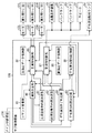
以上のような動作を実行するために、図13に示したメイン制御基板104は、スタート入力判定部60、レバー入力方向判定部61、メダル投入判定部62、役抽選部63、抽選テーブル64、抽選結果記憶部65、コマンド生成部66、コマンド送信部67、停止入力判定部68、遊技用リール制御部69、遊技用リール停止位置決定テーブル70、入賞判別部71、及び入賞処理部72を備えている。
(Main control board functions)
In order to execute the operation as described above, the main control board 104 shown in FIG. 13 includes a start input determination unit 60, a lever input direction determination unit 61, a medal insertion determination unit 62, a combination lottery unit 63, a lottery table 64, A lottery result storage unit 65, a command generation unit 66, a command transmission unit 67, a stop input determination unit 68, a gaming reel control unit 69, a gaming reel stop position determination table 70, a winning determination unit 71, and a winning processing unit 72 are provided. ing.

スタート入力判定部60、レバー入力方向判定部61、メダル投入判定部62、役抽選部63、コマンド生成部66、停止入力判定部68、遊技用リール制御部69、入賞判別部71、及び入賞処理部72は、例えば、前記CPU及び前記ROMに格納されているプログラムを用いて実現される。また、抽選結果記憶部65は、例えば前記RAMを用いて実現される。また、コマンド送信部67は、例えば、通信インターフェースを用いて実現される。なお、本実施形態における前記各部60〜72により実行される機能は例示であり、その他の機能を有していてもよいということは勿論である。   Start input determination unit 60, lever input direction determination unit 61, medal insertion determination unit 62, role lottery unit 63, command generation unit 66, stop input determination unit 68, game reel control unit 69, winning determination unit 71, and winning process The unit 72 is realized using, for example, a program stored in the CPU and the ROM. The lottery result storage unit 65 is realized using, for example, the RAM. Moreover, the command transmission part 67 is implement | achieved using a communication interface, for example. It should be noted that the functions executed by the units 60 to 72 in the present embodiment are examples, and it is needless to say that other functions may be provided.

(スタート入力判定部)
スタート入力判定部60は、スタートレバー41が遊技者により操作されたか否かを判定する。なお上述したように、本実施形態におけるスタートレバー41には、その上下左右の4方向の操作方向を検出する変位検出部111a〜111dが設けられている。これらの変位検出部111a〜111dにより、スタートレバー41が上、下、右、及び左の何れの方向に操作されたのかが検出される。
(Start input judgment part)
The start input determination unit 60 determines whether or not the start lever 41 has been operated by the player. As described above, the start lever 41 according to the present embodiment is provided with the displacement detection units 111a to 111d that detect the operation directions of the upper, lower, left, and right directions. These displacement detectors 111a to 111d detect whether the start lever 41 is operated in the upward, downward, right, or left direction.

(レバー入力方向判定部)
レバー入力方向判定部61は、遊技者により操作されたスタートレバー41の操作方向を検出する。なお、レバー入力方向判定部61は、前述したように変位検出部111a〜111dからの入力信号に基づいて、スタートレバー41の操作方向を検出する。
(Lever input direction determination unit)
The lever input direction determination unit 61 detects the operation direction of the start lever 41 operated by the player. The lever input direction determination unit 61 detects the operation direction of the start lever 41 based on the input signals from the displacement detection units 111a to 111d as described above.

(メダル投入判定部)
メダル投入判定部62は、遊技を行うのに必要なメダルが投入されたか否かを判定する。メダル投入判定部62は、メダル投入検出部43a及びベットスイッチ45からの信号に基づいて、メダルが投入されたか否かを判定する。
なお、前述したように、本実施形態では、1回の遊技で遊技者によって投入されるメダルの枚数(賭数)は、一律3枚に設定されている。したがって、本実施形態では、メダル投入判定部62は、3枚のメダルが投入されたか否かを判定する。
(Medal insertion determination part)
The medal insertion determination unit 62 determines whether or not a medal necessary for playing a game has been inserted. The medal insertion determination unit 62 determines whether or not a medal has been inserted based on signals from the medal insertion detection unit 43a and the bet switch 45.
As described above, in the present embodiment, the number of medals (the number of bets) inserted by the player in one game is uniformly set to three. Therefore, in this embodiment, the medal insertion determination unit 62 determines whether or not three medals have been inserted.

(役抽選部)
役抽選部63は、予め設けられた役の抽選を行うものである。役としては、例えば、特別役、小役、及びリプレイ(再遊技役)が挙げられる。
ここで、特別役とは、通常遊技から特別遊技(通常遊技以上にメダルの獲得が期待できる、遊技者にとって有利となる遊技)に移行させる役である。特別役としては一般に、BB(ビックボーナス)、RB(レギュラーボーナス)、及びSB(シングルボーナス)が挙げられる。これらのBB、RB及びSBは、それぞれ、特別遊技の1つであるBB遊技、RB遊技及びSB遊技に移行させるための役である。
(Role lottery)
The role lottery unit 63 performs lottery of a role provided in advance. Examples of the combination include a special combination, a small combination, and a replay (replay combination).
Here, the special role is a role that shifts from a normal game to a special game (a game that can be expected to win medals more than a normal game and is advantageous to the player). Special roles generally include BB (Big Bonus), RB (Regular Bonus), and SB (Single Bonus). These BB, RB, and SB are roles for shifting to BB games, RB games, and SB games, which are one of special games, respectively.

また、小役とは、予め定められた枚数のメダルが払い出される役である。小役の種類に応じて、メダルの払出し枚数が異なるように設定されている。さらに、リプレイ(再遊技役)とは、当該遊技でのメダルの投入枚数(ベットしたメダルの枚数)を維持して再遊技が行えるようにした役である。   The small combination is a combination in which a predetermined number of medals are paid out. The number of medals to be paid out is set differently depending on the type of the small role. Furthermore, the replay (replaying combination) is a combination that allows replaying while maintaining the number of inserted medals (the number of bet medals) in the game.

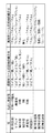
図14は、本実施形態における役の種類と払出し枚数等、及び図柄の組合せの一例を併せて示す図である。
図14に示すように、本実施形態では、特別役としてSBのみが設けられており、BB及びRBは設けられていない。また、小役として、2種類(第1小役及び第2小役)が設けられている。さらに、SBの入賞によりSB遊技に移行したときには、SB遊技中の役として、所定役が設けられている。
FIG. 14 is a diagram that also shows an example of the combination of the type of the combination, the number of payouts, and the symbols in this embodiment.
As shown in FIG. 14, in this embodiment, only SB is provided as a special role, and BB and RB are not provided. In addition, there are two types of small combinations (first small combination and second small combination). Furthermore, when the SB game is entered due to the winning of the SB, a predetermined combination is provided as a combination during the SB game.

そして、これらの各役に対応する遊技用リール31L、31C、及び31Rの図柄の組合せが予め定められている。また、各役に対応する演出用リール51L、51C、及び51Rの図柄の組合せも、予め定められている。   A combination of symbols of the game reels 31L, 31C, and 31R corresponding to each of the combinations is determined in advance. In addition, combinations of symbols of the effect reels 51L, 51C, and 51R corresponding to each combination are also determined in advance.

さらに、本実施形態では、遊技用リール31L、31C、及び31Rの当選役の図柄の組合せと、遊技用リール31L、31C、及び31Rのその当選役の図柄の組合せに対応する演出用リール51L、51C、及び51Rの図柄の組合せとは、異なる図柄の組合せに設定されている。   Further, in the present embodiment, the effect reels 51L, 31L, 31C, and 31R corresponding to the winning combination and the reels 31L, 31C, and 31R corresponding to the winning combination The combination of symbols 51C and 51R is set to a different symbol combination.

例えば、図14に示したように、第1小役では、遊技用リール31L、31C、及び31Rの図柄の組合せは、「スイカ」−「ぶどう」−「レモン」に設定されているが、これに対応する演出用リール51L、51C、及び51Rの図柄の組合せは、「ベル」−「ベル」−「ベル」に設定されている。   For example, as shown in FIG. 14, in the first small role, the combination of symbols of the game reels 31L, 31C, and 31R is set to "watermelon"-"grape"-"lemon". The combination of symbols of the effect reels 51L, 51C, and 51R corresponding to is set to "bell"-"bell"-"bell".

さらに、本実施形態では、遊技用リール31L、31C、及び31Rの第1役(例えばSB)の図柄の組合せと、遊技用リール31L、31C、及び31Rの第2役(前記第1役と異なる役を意味する。例えば第1小役)の図柄の組合せとは、異なる図柄の組合せに設定されている。例えば、図9に示したように、SBの図柄の組合せは、「スイカ」−「桃」−「桃」に設定されているが、第1小役の図柄の組合せは、「スイカ」−「ぶどう」−「レモン」に設定されている。   Further, in the present embodiment, the combination of symbols of the first role (for example, SB) of the game reels 31L, 31C, and 31R and the second role of the game reels 31L, 31C, and 31R (different from the first role). The combination of symbols of a symbol (for example, the first small role) is set to a combination of symbols different from each other. For example, as shown in FIG. 9, the combination of symbols of SB is set to “watermelon”-“peach”-“peach”, but the combination of symbols of the first small role is “watermelon”-“ It is set to "Grape"-"Lemon".

そして、この場合に、遊技用リール31L、31C、及び31Rの第1役の図柄の組合せに対応する演出用リール51L、51C、及び51Rの図柄の組合せと、第2役の図柄の組合せに対応する演出用リール51L、51C、及び51Rの図柄の組合せとは、同一の図柄の組合せに設定されている。例えば、演出用リール51L、51C、及び51Rでは、SBの図柄の組合せと、第1小役の図柄の組合せとが、ともに同一の「ベル」−「ベル」−「ベル」に設定されている。   And in this case, it corresponds to the combination of the symbols of the effect reels 51L, 51C and 51R corresponding to the combination of the symbols of the first role of the game reels 31L, 31C and 31R and the combination of the symbols of the second role. The symbol combinations of the effect reels 51L, 51C, and 51R are set to the same symbol combination. For example, in the production reels 51L, 51C, and 51R, the combination of symbols of SB and the combination of symbols of the first small role are set to the same “bell”-“bell”-“bell”. .

以上のように図柄の組合せを設定することにより、演出用リール51L、51C、及び51Rの図柄の組合せを見ただけでは、どの役が入賞したか等を、遊技者に判別させないようにすることができる。   By setting the combination of symbols as described above, it is possible to prevent the player from determining which combination has won a prize simply by looking at the combination of symbols on the production reels 51L, 51C, and 51R. Can do.

役抽選部63は、例えば、役抽選用の乱数発生手段(ハードウェア乱数等)と、この乱数発生手段が発生する乱数を抽出する乱数抽出手段と、この乱数抽出手段が抽出した乱数値に基づいて、役の当選の有無及び当選役を判定する判定手段とを備えている。   The role lottery unit 63 is based on, for example, a random number generation means (hardware random number, etc.) for role lottery, a random number extraction means for extracting a random number generated by the random number generation means, and a random value extracted by the random number extraction means. And determining means for determining whether or not a winning combination has been won and a winning combination.

役抽選部63の乱数発生手段は、所定の領域(例えば10進法で0〜65535)の乱数を発生させる。乱数抽出手段は、乱数発生手段によって発生した乱数を抽出する。本実施形態では、メダル投入判定部62でメダルが投入された後に、スタート入力判定部60でスタートレバー41が操作されたと判定された場合に、乱数を抽出するようにしている。そして、判定手段は、乱数抽出手段により抽出された乱数値を、後述する抽選テーブル64と照合することにより、その乱数値が属する領域に対応する役を決定する。例えば、抽出した乱数値が第1小役の当選領域に属する場合には、第1小役が当選したと判定する。一方、抽出した乱数値が非当選領域に属する場合は、非当選と判定する。   The random number generation means of the role lottery unit 63 generates random numbers in a predetermined area (for example, 0 to 65535 in decimal notation). The random number extraction unit extracts the random number generated by the random number generation unit. In the present embodiment, random numbers are extracted when the start input determination unit 60 determines that the start lever 41 has been operated after the medal insertion determination unit 62 has inserted a medal. Then, the determination unit determines the combination corresponding to the region to which the random number value belongs by comparing the random number value extracted by the random number extraction unit with a lottery table 64 described later. For example, when the extracted random number value belongs to the winning area of the first small combination, it is determined that the first small combination has been won. On the other hand, when the extracted random number value belongs to the non-winning area, it is determined that it is non-winning.

役抽選部63は、図14に示したように、通常遊技中は、特別役であるSB、2種類の小役(第1小役及び第2小役)、リプレイ(再遊技役)、及び非当選の中から、抽出した乱数値に基づいて、何れかを選択する。すなわち、当選役あるいは非当選を判定する。また、SBゲーム中は、抽出した乱数値に基づいて、所定役の当選あるいは非当選を判定する。   As shown in FIG. 14, the role lottery unit 63 is a special role SB, two kinds of small roles (first small role and second small role), replay (re-playing role), and Based on the extracted random value, select one of the non-wins. That is, the winning combination or non-winning is determined. Further, during the SB game, whether or not a predetermined role is won is determined based on the extracted random number value.

なお、本実施形態では、SBの当選確率として、通常確率と高確率(本実施形態では通常確率の10倍)との2種類を備えており、役抽選部63は、SBの当選確率を、通常確率及び高確率の何れにするかの抽選も行うようにしている。
スロットマシン10の電源投入直後におけるSBの当選確率は、通常確率に設定されている。その後、役抽選部63は、毎遊技ごとに、SBの当選確率を高確率にするか否かの抽選を行う。高確率に当選した後も、役抽選部63は、さらに抽選を継続する。この場合には、SBの当選確率を高確率から通常確率に戻すか否かの抽選を行う。
In the present embodiment, there are two types of SB winning probabilities, a normal probability and a high probability (10 times the normal probability in this embodiment), and the winning lottery unit 63 determines the SB winning probability as A lottery for normal probability or high probability is also performed.
The SB winning probability immediately after the slot machine 10 is turned on is set to the normal probability. Thereafter, the winning lottery unit 63 performs a lottery to determine whether or not to increase the SB winning probability for each game. Even after winning with high probability, the role lottery unit 63 further continues the lottery. In this case, a lottery is performed as to whether or not to return the SB winning probability from the high probability to the normal probability.

そして、この抽選で当選したときは、SBの当選確率が高確率から通常確率に戻される。通常確率に戻されると、前述したように、役抽選部63は、SB当選確率を高確率にするか否かの抽選を再度行う。以上により、遊技中のSB当選確率は、通常確率と高確率とを行き来することとなる。   When winning in this lottery, the winning probability of SB is returned from the high probability to the normal probability. When the normal probability is restored, as described above, the role lottery unit 63 performs the lottery again as to whether or not to increase the SB winning probability. As described above, the SB winning probability during the game goes back and forth between the normal probability and the high probability.

(抽選テーブル)
抽選テーブル64は、メイン制御基板104に設けられている前記ROMに個別に格納されており、各役の当選確率を定めたものである。抽選テーブル64は、それぞれ所定の範囲の抽選領域を有する。この抽選領域は、各役の当選領域及び非当選領域に分けられているとともに、予め設定された当選確率となるように所定の割合に設定されている。
なお、図示しないが、各役の当選領域及び非当選領域は、出玉率の設定値ごとに定められている。
(Lottery table)
The lottery table 64 is individually stored in the ROM provided on the main control board 104, and determines the winning probability of each combination. Each lottery table 64 has a predetermined range of lottery areas. The lottery area is divided into a winning area and a non-winning area for each combination, and is set to a predetermined ratio so as to have a preset winning probability.
Although not shown, the winning area and the non-winning area of each combination are determined for each set value of the payout rate.

また、抽選テーブル64は、SBの当選確率が通常確率に設定された抽選テーブルと、高確率に設定された抽選テーブルとを備えている。SBの当選確率が通常確率に設定されているときには、役抽選部63は、SBの当選確率が通常確率に設定された抽選テーブルを用いて役の抽選を行う。一方、SBの当選確率が高確率に設定されているときには、役抽選部63は、SBの当選確率が高確率に設定された抽選テーブルを用いて役の抽選を行う。   The lottery table 64 includes a lottery table in which the SB winning probability is set to a normal probability and a lottery table in which a high probability is set. When the winning probability of the SB is set to the normal probability, the combination lottery unit 63 performs the lottery of the combination using the lottery table in which the winning probability of the SB is set to the normal probability. On the other hand, when the winning probability of the SB is set to a high probability, the winning combination lottery unit 63 performs the drawing of the winning combination using the lottery table in which the winning probability of the SB is set to a high probability.

さらに、本実施形態では、当選役のうち、SB、及びSBゲーム中の所定役は、ストップスイッチ42L、42C、及び42Rが所定の操作順番で操作されたときに限り、遊技用リール31L、31C、及び31Rの停止可能位置の範囲内において、その当選役(SBの当選時はそのSB、及びSB遊技中における所定役の当選時はその所定役)に対応する図柄の組合せが有効ラインに停止する(入賞する)ように遊技用リール31L、31C、及び31Rの動作が制御される役である。言い換えれば、SB又は所定役に当選しても、ストップスイッチ42L、42C、及び42Rが、所定の操作順番以外の操作順番で操作されたときは、その当選役に対応する図柄の組合せが有効ラインに停止しない。   Further, in the present embodiment, among the winning combinations, the predetermined combination in the SB and SB games is the game reels 31L, 31C only when the stop switches 42L, 42C, and 42R are operated in a predetermined operation order. , And 31R within the range of possible stop positions, the combination of symbols corresponding to the winning combination (the SB when winning the SB and the predetermined combination when winning the predetermined combination during SB game) stops on the active line This is a role in which the operations of the gaming reels 31L, 31C, and 31R are controlled so as to perform (win). In other words, even if the SB or the predetermined combination is won, if the stop switches 42L, 42C, and 42R are operated in an operation order other than the predetermined operation order, the combination of symbols corresponding to the winning combination is an effective line. Never stop.

ここで、左、中、右の各遊技用リール31L、31C、及び31Rにそれぞれ対応するストップスイッチ42L、42C、及び42Rを、左、中、右で表すと、ストップスイッチ42L、42C、及び42Rの操作順番としては、「左中右」、「左右中」、「中左右」、「中右左」、「右左中」、及び「右中左」の6通り挙げられる。
本実施形態では、SB及び所定役には、それぞれ6通りの操作順番が均等(1/6)に割り当てられている。例えば、通常遊技中のSBの当選確率が1/15であるとすると、「左中右」、「左右中」、「中左右」、「中右左」、「右左中」、及び「右中左」の各SB当選確率は、それぞれ1/90(=1/15×1/6)に割り当てられている。
Here, when the stop switches 42L, 42C, and 42R corresponding to the left, middle, and right game reels 31L, 31C, and 31R, respectively, are represented by left, middle, and right, the stop switches 42L, 42C, and 42R. The operation order of “left middle right”, “left / right middle”, “middle left / right”, “middle right left”, “right left middle”, and “right middle left” can be mentioned.
In the present embodiment, six operation orders are assigned equally (1/6) to the SB and the predetermined combination, respectively. For example, assuming that the winning probability of SB in a normal game is 1/15, “left middle right”, “left / right middle”, “middle left / right”, “middle right left”, “right left middle”, and “right middle left” The SB winning probabilities of “1” are assigned to 1/90 (= 1/15 × 1/6).

(抽選結果記憶部)
抽選結果記憶部65は、役抽選部63による役の抽選結果を記憶するためのものである。抽選結果記憶部65は、全ての役ごとに当選役フラグを備えている。例えば、いずれかの役に当選した場合に、メイン制御部60が、その役に対応する当選役フラグをオンにすることで、各役の当選及び非当選を記憶する。また、ストップスイッチ42L、42C、及び42Rの操作順番が定められているSB又は所定役に当選したときは、その役の当選とともに、ストップスイッチ42L、42C、及び42Rの操作順番(その当選役を入賞させるための操作順番)を特定する押し順IDも併せて記憶される。この他、抽選結果記憶部65は、役抽選部63で抽選されたSBの当選確率も記憶する。
(Lottery result storage)
The lottery result storage unit 65 is for storing the lottery result of the combination by the combination lottery unit 63. The lottery result storage unit 65 includes a winning combination flag for every combination. For example, when one of the winning combinations is won, the main control unit 60 stores the winning and non-winning of each winning combination by turning on the winning winning flag corresponding to the winning combination. In addition, when winning an SB or a predetermined role in which the operation order of the stop switches 42L, 42C, and 42R is determined, along with the winning of the role, the operation order of the stop switches 42L, 42C, and 42R (the winning role is changed) The push order ID for specifying the operation order for winning is also stored. In addition, the lottery result storage unit 65 also stores the winning probability of the SB lottery by the combination lottery unit 63.

(コマンド生成部)
コマンド生成部66は、サブ制御基板108に送信するコマンドを生成する。本実施形態では、例えば以下のようなコマンドを生成する。
(Command generator)
The command generation unit 66 generates a command to be transmitted to the sub control board 108. In the present embodiment, for example, the following command is generated.

(1)デモ選択表示コマンド
デモ選択表示コマンドは、遊技を行っていないとき、すなわち、遊技用リール31L、31C、及び31Rの全てが停止しているときに、ストップスイッチ42L、42C、及び42Rの何れかが遊技者により操作されたと判定された場合に、デモ選択用画像13bを液晶表示装置13に表示させることをサブ制御基板108に指示するためのものである。
(1) Demo selection display command The demonstration selection display command is used when the stop switches 42L, 42C, and 42R are used when the game is not being performed, that is, when all of the game reels 31L, 31C, and 31R are stopped. This is for instructing the sub-control board 108 to display the demonstration selection image 13b on the liquid crystal display device 13 when it is determined that any of them is operated by the player.

(2)デモ表示強制終了コマンド
デモ表示強制終了コマンドは、メダル投入判定部62によりメダルが投入されたと判定された場合に、デモ選択用画像13bの表示を強制的に中止させることををサブ制御基板108に指示するためのものである。
(2) Demo display forced end command The demo display forced end command is a sub-control for forcibly stopping the display of the demo selection image 13b when the medal insertion determining unit 62 determines that a medal has been inserted. This is for instructing the substrate 108.

(3)演出選択コマンド
演出選択コマンドは、レバー入力方向判定部61で判定されたスタートレバー41の操作方向をサブ制御基板108に指示するためのものである。すなわち、演出選択用画像13a又はデモ選択用画像13bに基づいて遊技者により選択された演出が何れであるかをサブ制御基板108に指示するためのものである。
(3) Effect Selection Command The effect selection command is for instructing the sub-control board 108 the operation direction of the start lever 41 determined by the lever input direction determination unit 61. That is, it is for instructing the sub-control board 108 which effect is selected by the player based on the effect selection image 13a or the demonstration selection image 13b.

(4)演出コマンド
演出コマンドは、役抽選部63により行われた役の抽選結果や、SBの当選確率等、サブ制御基板108で演出を決定するのに必要な指示を、サブ制御基板108に行うためのものである。ここで、役の抽選結果とは、例えば、当選役に係る図柄を特定するための図柄ID等である。
(4) Effect Command The effect command is an instruction necessary for determining the effect on the sub-control board 108, such as the result of the role lottery performed by the role lottery unit 63, the winning probability of SB, and the like to the sub-control board 108. Is to do. Here, the lottery result of the combination is, for example, a symbol ID for identifying the symbol related to the winning combination.

(5)選択用画像表示中止コマンド
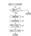
選択用画像表示中止コマンドは、デモ選択表示コマンドをサブ制御基板108に送信してから、一定時間の間に演出選択コマンドを生成することができない場合、又は遊技者選択系演出を行うことを指示する演出コマンドをサブ制御基板108に送信してから、一定時間の間に演出選択コマンドを生成することができない場合に、演出選択用画像13a又はデモ選択用画像13bの表示を中止させることをサブ制御基板108に指示するためのものである。
(5) Selection image display stop command The selection image display stop command is used when an effect selection command cannot be generated within a certain period of time after a demonstration selection display command is transmitted to the sub-control board 108, or a game When an effect selection command cannot be generated within a certain period of time after an effect command instructing to perform a person selection system effect is transmitted to the sub-control board 108, an effect selection image 13a or a demonstration selection image This is for instructing the sub-control board 108 to stop the display of 13b.

また、役抽選部63による役の抽選で、SB又は所定役に当選したときには、その当選役を入賞させるための押し順IDも、この演出コマンドに含まれる。また、この演出コマンドは、毎遊技ごとに生成される。以下の説明では、役の抽選結果の情報を「当選役情報」と称し、SBの当選確率の情報を「SB当選確率情報」と称する。   In addition, when the SB or the predetermined role is won in the role lottery by the role lottery unit 63, the push order ID for winning the winning combination is also included in this effect command. This effect command is generated for each game. In the following description, information on the lottery result of the combination is referred to as “winning combination information”, and information on the winning probability of SB is referred to as “SB winning probability information”.

なお、以上のような各コマンドに基づいた動作をサブ制御基板108で実行することができるように、スタートレバー41や、ストップスイッチ42L、42C、及び42R等の操作内容についての情報も、前記各コマンドに含まれる。また、必要に応じて、スタートレバー41や、ストップスイッチ42L、42C、及び42R等の操作内容についての情報を、前記各コマンドとは別個にサブ制御基板108に送信するようにしてもよい。   It should be noted that information about the operation contents of the start lever 41 and the stop switches 42L, 42C, and 42R is also provided so that the operation based on each command as described above can be executed by the sub-control board 108. Included in the command. Further, if necessary, information on the operation contents of the start lever 41 and the stop switches 42L, 42C, and 42R may be transmitted to the sub-control board 108 separately from the respective commands.

(コマンド送信部)
コマンド送信部67は、コマンド生成部66で生成されたコマンドをサブ制御基板108に送信する。
(Command transmission part)
The command transmission unit 67 transmits the command generated by the command generation unit 66 to the sub control board 108.

(停止入力判定部)
停止入力判定部68は、ストップスイッチ42L、42C、及び42Rが操作されたか否かを判定するとともに、これらストップスイッチ42L、42C、及び42Rの何れが操作されたかを判定する。
(Stop input judgment part)
The stop input determination unit 68 determines whether or not the stop switches 42L, 42C, and 42R are operated, and determines which of the stop switches 42L, 42C, and 42R is operated.

(遊技用リール制御部)
遊技用リール制御部69は、メダル投入判定部62でメダルが投入された後に、スタート入力判定部60でスタートレバー41が操作されたと判定された場合に、ステッピングモータ32L、32C、及び32Rを駆動して、遊技用リール31L、31C、及び31Rを始動させる。
(Game reel control unit)
The gaming reel control unit 69 drives the stepping motors 32L, 32C, and 32R when the start input determination unit 60 determines that the start lever 41 is operated after the medal insertion determination unit 62 inserts a medal. Then, the game reels 31L, 31C, and 31R are started.

その後、遊技用リール制御部69は、抽選結果記憶部65に記憶されている役の抽選結果と、ストップスイッチ42L、42C、及び42Rが操作(オン)されたときのタイミングとに基づいて、遊技用リール停止位置決定テーブル70を参照して、遊技用リール31L、31C、及び31Rの停止位置を決定する。そして、ステッピングモータ32L、32C、及び32Rを駆動制御して、その決定した位置に遊技用リール31L、31C、及び31Rを停止させる。   Thereafter, the gaming reel control unit 69 plays the game based on the lottery result of the combination stored in the lottery result storage unit 65 and the timing when the stop switches 42L, 42C, and 42R are operated (turned on). Referring to the reel stop position determination table 70, the stop positions of the game reels 31L, 31C, and 31R are determined. Then, the stepping motors 32L, 32C, and 32R are driven and controlled, and the gaming reels 31L, 31C, and 31R are stopped at the determined positions.

例えば、遊技用リール制御部69は、小役又はリプレイに当選した遊技では、遊技用リール31L、31C、及び31Rの停止可能位置の範囲内において、当選した小役又はリプレイに対応する図柄の組合せを有効ラインに停止させるように、遊技用リール31L、31C、及び31Rを停止させる。   For example, the game reel control unit 69, in the game won for the small role or replay, within the range of the stop positions of the game reels 31L, 31C, and 31R, the combination of symbols corresponding to the selected small role or replay The game reels 31L, 31C, and 31R are stopped so that is stopped on the active line.

(遊技用リール停止位置決定テーブル)
遊技用リール停止位置決定テーブル70は、メイン制御基板104に設けられている前記ROMに個別に格納されており、役抽選部63による役の抽選結果と、ストップスイッチ42L、42C、及び42Rが操作された瞬間の遊技用リール31L、31C、及び31Rの位置とから、遊技用リール31L、31C、及び31Rの図柄の停止位置を定めたものである。遊技用リール停止位置決定テーブル70には、当選した役ごとのテーブルと、非当選時(いずれの役にも当選していないとき)のテーブルとがある。
(Game reel stop position determination table)
The gaming reel stop position determination table 70 is individually stored in the ROM provided on the main control board 104, and the lottery result of the combination by the combination lottery unit 63 and the stop switches 42L, 42C, and 42R are operated. The stop positions of the symbols of the game reels 31L, 31C, and 31R are determined from the positions of the game reels 31L, 31C, and 31R at the moment of being played. The gaming reel stop position determination table 70 includes a table for each winning combination and a table for non-winning (when no winning combination is selected).

例えば、いずれの役にも当選していないときに用いられる遊技用リール停止位置決定テーブルは、いずれかの役に対応する図柄の組合せが有効ラインに停止しないような、遊技用リール31L、31C、及び31Rの停止位置が定められている。また、小役又はリプレイの当選時に用いられる遊技用リール停止位置決定テーブルは、遊技用リール31L、31C、及び31Rの停止可能位置の範囲内において、その当選した小役又はリプレイに対応する図柄の組合せが有効ラインに停止するような、遊技用リール31L、31C、及び31Rの停止位置が定められている。   For example, the gaming reel stop position determination table used when none of the winning combinations is won, the gaming reels 31L, 31C, and the like so that the combination of symbols corresponding to any winning combination does not stop on the active line. And the stop position of 31R is defined. In addition, the game reel stop position determination table used at the time of winning the small role or replay has a symbol corresponding to the selected small role or replay within the range of stop positions of the game reels 31L, 31C, and 31R. The stop positions of the game reels 31L, 31C, and 31R are determined so that the combination stops at the active line.

(遊技用リール制御部の制御処理)
以上のような遊技用リール停止位置決定テーブル70を用いて、いずれかの役に対応する図柄の組合せを有効ラインに停止させるときは、遊技用リール制御部69は、遊技用リール31L、31C、及び31Rの停止可能位置の範囲内において、その役に対応する図柄の組合せを構成する図柄の引込み制御を行う。すなわち、ストップスイッチ42L、42C、及び42Rの操作(オン)を検知した位置で、対応する遊技用リール31L、31C、及び31Rを直ちに停止させると、その役に係る図柄が有効ラインに停止しないときには、遊技用リール31L、31C、及び31Rを停止制御するときに、遊技用リール31L、31C、及び31Rの停止位置を移動制御することにより、有効ラインにその役に係る図柄を積極的に停止させるようにする。
(Control processing of game reel control unit)
Using the gaming reel stop position determination table 70 as described above, when the combination of symbols corresponding to any of the combinations is stopped on the active line, the gaming reel control unit 69 uses the gaming reels 31L, 31C, And within the range of the 31R stoppable position, the drawing control of the symbols constituting the symbol combination corresponding to the combination is performed. That is, when the corresponding game reels 31L, 31C, and 31R are immediately stopped at the position where the operation (on) of the stop switches 42L, 42C, and 42R is detected, the symbol related to the combination does not stop on the active line. When the game reels 31L, 31C, and 31R are controlled to stop, by moving and controlling the stop positions of the game reels 31L, 31C, and 31R, the symbol related to the role is actively stopped on the active line. Like that.

図14に示したように、本実施形態では、各当選役に対応する遊技用リール31L、31C、及び31Rの図柄の組合せがそれぞれ定められているが、前述したように、これらの各役に対応する図柄の組合せは、第2小役を除き、遊技用リール31L、31C、及び31Rの停止制御の範囲内(ストップスイッチ42L、42C、及び42Rが操作された瞬間の図柄位置を含めて3図柄以内)で、常に、有効ラインに停止させることができる。すなわち、第2小役を除く役の当選時は、遊技者は、特定の図柄を狙ってストップスイッチ42L、42C、及び42Rを操作しなくても(目押しをすることなく)、当選役に対応する図柄の組合せを有効ラインに停止させることができる。特に、遊技用リール31L、31C、及び31Rの図柄は、演出用リール51L、51C、及び51Rの図柄よりも小さいために、遊技用リール31L、31C、及び31Rでは、特定の図柄を狙ってストップスイッチ42L、42C、及び42Rを操作することが容易でなくなることが考えられるが、本実施形態のようにすれば、このような操作をしなくても当選役に対応する図柄の組合せを有効ラインに停止させることができる。   As shown in FIG. 14, in this embodiment, the combination of symbols of the game reels 31L, 31C, and 31R corresponding to each winning combination is determined. However, as described above, The corresponding symbol combinations are within the range of stop control of the gaming reels 31L, 31C, and 31R except for the second small part (including the symbol position at the moment when the stop switches 42L, 42C, and 42R are operated). Within the design), it can always stop at the active line. That is, when winning a role other than the second small role, the player can win the winning role without operating the stop switches 42L, 42C, and 42R (without pressing the target) without aiming for a specific symbol. Corresponding symbol combinations can be stopped on the active line. In particular, since the symbols of the game reels 31L, 31C, and 31R are smaller than the symbols of the effect reels 51L, 51C, and 51R, the game reels 31L, 31C, and 31R aim at a specific symbol and stop. Although it may be difficult to operate the switches 42L, 42C, and 42R, according to the present embodiment, the combination of symbols corresponding to the winning combination is effective lines without performing such an operation. Can be stopped.

一方、第2小役の当選時は、例えば、図5に示した左の遊技用リール31Lの図柄において、上から6番目(「桃」の図柄)〜8番目の図柄が有効ライン上に位置する瞬間にストップスイッチ42Lが操作されると、第2小役に対応する図柄の組合せを有効ラインに停止させることができる。しかし、それ以外の図柄が有効ライン上に位置する瞬間にストップスイッチ42Lが操作されたときには、第2小役に対応する図柄の組合せは、有効ラインに停止しない。   On the other hand, at the time of winning the second small role, for example, in the symbol of the left gaming reel 31L shown in FIG. 5, the symbols from the sixth (“peach” symbol) to the eighth symbol are positioned on the active line. When the stop switch 42L is operated at the moment, the combination of symbols corresponding to the second small role can be stopped on the active line. However, when the stop switch 42L is operated at the moment when other symbols are positioned on the active line, the combination of symbols corresponding to the second small part does not stop on the active line.

よって、第2小役以外の役の当選時には、その役に対応する図柄の組合せが有効ラインに常に停止するが、第2小役の当選時には、ストップスイッチ42Lの操作タイミングに応じて、第2小役に対応する図柄の組合せが有効ラインに停止するときもあれば、停止しないときもある。   Therefore, when a combination other than the second small combination is won, the combination of symbols corresponding to that combination always stops on the active line. However, when the second small combination is selected, the second combination depends on the operation timing of the stop switch 42L. The combination of symbols corresponding to the small role may or may not stop at the active line.

さらに、SB又は所定役に当選したときに用いられる遊技用リール停止位置決定テーブル70は、当選したSB又は所定役の図柄の組合せを有効ラインに停止させないような、遊技用リール31L、31C、及び31Rの停止位置を定めている。遊技者により操作されたストップスイッチ42L、42C、及び42Rの操作順番を検知し、その操作順番がその当選役の操作順番と一致していない場合には、遊技用リール制御部69は、この遊技用リール停止位置決定テーブル70を用いて遊技用リール31L、31C、及び31Rを停止制御する。一方、操作順番がこの当選役の操作順番と一致している場合には、遊技用リール制御部69は、遊技用リール停止位置決定テーブル70を用いずに、当選役に係る図柄を有効ラインに引き込む制御を行うようにする。   In addition, the gaming reel stop position determination table 70 used when winning the SB or the predetermined combination, the gaming reels 31L, 31C, and the like so as not to stop the combination of the winning SB or the predetermined combination of symbols on the active line, and A stop position of 31R is determined. When the operation order of the stop switches 42L, 42C, and 42R operated by the player is detected and the operation order does not coincide with the operation order of the winning combination, the gaming reel control unit 69 performs this game. The game reels 31L, 31C, and 31R are controlled to stop using the reel stop position determination table 70. On the other hand, when the operation order matches the operation order of the winning combination, the gaming reel control unit 69 sets the symbol related to the winning combination to the active line without using the gaming reel stop position determination table 70. Do the pull-in control.

このようにすれば、ストップスイッチ42L、42C、及び42Rの操作順番ごとに遊技用リール停止位置決定テーブル70を設けたり、あるいは制御を複雑にしたりすることなく、SB又は所定役の当選時に、遊技用リール31L、31C、及び31Rの停止制御を行うことができる。 ただし、ストップスイッチ42L、42C、及び42Rの操作順番に対応させて、遊技用リール停止位置決定テーブル70を設けても良いのは勿論である。   In this way, the game reel stop position determination table 70 is not provided for each operation order of the stop switches 42L, 42C, and 42R, or the game is performed at the time of winning the SB or the predetermined role without complicating the control. The stop control of the reels 31L, 31C, and 31R can be performed. However, it goes without saying that the gaming reel stop position determination table 70 may be provided in correspondence with the operation order of the stop switches 42L, 42C, and 42R.

(入賞判別部)
入賞判別部71は、遊技用リール31L、31C、及び31Rの停止時に、有効ラインに停止した図柄の組合せが、いずれかの役に対応する図柄の組合せと一致するか否かを判別し、いずれかの役に入賞したか否かを判別する。具体的に、入賞判別部71は、ステッピングモータ32L、32C、及び32Rの停止時の角度やステップ数等を検知することにより、有効ライン上の図柄を判別する。
(Winning determination section)
The winning determination unit 71 determines whether the combination of symbols stopped on the active line matches the combination of symbols corresponding to any combination when the game reels 31L, 31C, and 31R are stopped. It is determined whether or not a winning combination is made. Specifically, the winning determination unit 71 determines the symbol on the effective line by detecting the angle and the number of steps when the stepping motors 32L, 32C, and 32R are stopped.

なお、入賞判別部71は、遊技用リール31L、31C、及び31Rが実際に停止してから図柄の組合せを判別する必要はない。例えば、遊技用リール停止位置決定テーブル70によって遊技用リール31L、31C、及び31Rの停止位置が定められた時点で、有効ライン上の図柄の組合せを判別することも可能である。   The winning determination unit 71 does not need to determine the combination of symbols after the gaming reels 31L, 31C, and 31R are actually stopped. For example, when the stop positions of the game reels 31L, 31C, and 31R are determined by the game reel stop position determination table 70, it is possible to determine the combination of symbols on the active line.

(入賞処理部)
入賞処理部72は、遊技用リール31L、31C、及び31Rの停止時に有効ラインに停止した図柄の組合せが、いずれかの役に対応する図柄の組合せと一致すると入賞判別部71により判別され、その役の入賞となったときに、その入賞役に応じた所定枚数のメダルを遊技者に対して払い出す指示をメダル払出装置47に行う。なお、所定枚数のメダルが貯留していない場合、入賞処理部72は、メダル払出装置47に対して指示を出さずに、メダルの貯留数(クレジット)を加算する処理等を行ってもよい。また、リプレイ(再遊技役)の入賞となった場合、入賞処理部72は、メダルを払い出したり、クレジットを加算したりすることなく、当該遊技で投入されたメダルの枚数を再投入する。
(Winning process department)
The winning processing unit 72 is determined by the winning determining unit 71 when the combination of symbols stopped on the active line when the gaming reels 31L, 31C, and 31R are stopped matches the combination of symbols corresponding to any combination, When a winning combination is awarded, the medal paying device 47 is instructed to pay out to the player a predetermined number of medals corresponding to the winning combination. When a predetermined number of medals are not stored, the winning processing unit 72 may perform a process of adding the number of stored medals (credits) without issuing an instruction to the medal payout device 47. Also, when a replay (re-game player) win is made, the winning processing unit 72 re-inserts the number of medals inserted in the game without paying out medals or adding credits.

(サブ制御基板の機能)
図13に示したサブ制御基板108は、コマンド受信部80、主演出表示内容決定部81、副演出表示内容決定部82、デモ演出内容決定部83、デモ演出強制終了判定部84、主演出制御部85、主演出データ格納部86、副演出制御部87、副演出データ格納部88、デモ演出報知制御部89、及び演出決定部90を備えている。
主演出表示内容決定部81、副演出表示内容決定部82、デモ演出内容決定部83、デモ演出強制終了判定部84、主演出制御部85、副演出制御部87、副演出データ格納部88、デモ演出報知制御部89、及び演出決定部90は、例えば、前記CPU及び前記ROMのプログラムを用いて実現される。また、コマンド受信部80は、例えば、通信インターフェースを用いて実現される。なお、本実施形態における前記各部80〜89により実行される機能は例示であり、その他の機能を有していてもよいということは勿論である。
(Sub control board function)
The sub control board 108 shown in FIG. 13 includes a command receiving unit 80, a main effect display content determining unit 81, a sub effect display content determining unit 82, a demo effect content determining unit 83, a demo effect forced termination determining unit 84, and a main effect control. Unit 85, main effect data storage unit 86, subsidiary effect control unit 87, subsidiary effect data storage unit 88, demonstration effect notification control unit 89, and effect determination unit 90.
Main effect display content determination unit 81, sub-effect display content determination unit 82, demo effect content determination unit 83, demo effect forced termination determination unit 84, main effect control unit 85, sub-effect control unit 87, sub-effect data storage unit 88, The demonstration effect notification control unit 89 and the effect determination unit 90 are realized using, for example, the CPU and the ROM program. The command receiving unit 80 is realized using, for example, a communication interface. It should be noted that the functions executed by the units 80 to 89 in the present embodiment are examples, and it is needless to say that other functions may be provided.

(コマンド受信部)
コマンド受信部80は、メイン制御基板104のコマンド送信部67から送信されたコマンドを受信する。
(Command receiver)
The command receiving unit 80 receives a command transmitted from the command transmitting unit 67 of the main control board 104.

(演出決定部)
演出決定部90は、コマンド受信部80が演出コマンドを受信すると、その演出コマンドに含まれている「当選役情報」及び「SB当選確率情報」等に基づいて、出力すべき演出(演出用リール51L、51C、及び51Rの動作を含む)を決定する。本実施形態では、具体的に以下のようにして、出力すべき演出を決定するようにしている。
(Direction determination part)
When the command receiving unit 80 receives an effect command, the effect determining unit 90 outputs an effect to be output (effect reel) based on the “winning role information” and “SB winning probability information” included in the effect command. 51L, 51C, and 51R are included). In the present embodiment, an effect to be output is determined specifically as follows.

(1) 特定遊技に係る演出の決定
演出決定部90は、特定遊技を実行するか否かを決定する。本実施形態では、例えばソフトウェア乱数を用いて抽選により決定する。また、演出コマンドに含まれている「SB当選確率情報」が高確率である場合に限り、特定遊技を実行するか否かの抽選を行う。なお、本実施形態では、特定遊技を実行すると決定したときは、その特定遊技が終了するまで、特定遊技を実行するか否かの抽選は行わないようにする。
(1) Determination of effect related to specific game The effect determination unit 90 determines whether or not to execute a specific game. In the present embodiment, it is determined by lottery using, for example, software random numbers. Further, only when the “SB winning probability information” included in the effect command has a high probability, a lottery for determining whether or not to execute the specific game is performed. In this embodiment, when it is determined that the specific game is to be executed, the lottery for determining whether or not to execute the specific game is not performed until the specific game is completed.

図14に示したように、本実施形態では、特定遊技として、3種類の特定遊技(第1特定遊技、第2特定遊技、及び第3特定遊技)が設けられている。特定遊技を実行すると決定したときには、第1特定遊技、第2特定遊技、及び第3特定遊技のうち、いずれの特定遊技を実行するかを、ソフトウェア乱数を用いた抽選により決定する。本実施形態では、第1特定遊技に係る図柄の選択率が約77%、第2特定遊技に係る図柄の選択率が約20%、第3特定遊技に係る図柄の選択率が約3%に設定されている。   As shown in FIG. 14, in the present embodiment, three types of specific games (first specific game, second specific game, and third specific game) are provided as specific games. When it is determined that the specific game is to be executed, it is determined by lottery using software random numbers which one of the first specific game, the second specific game, and the third specific game is to be executed. In this embodiment, the symbol selection rate for the first specific game is about 77%, the symbol selection rate for the second specific game is about 20%, and the symbol selection rate for the third specific game is about 3%. Is set.

ここで、「特定遊技」とは、SBの当選時、及びSB遊技中の所定役の当選時に、ストップスイッチ42L、42C、及び42Rの操作順番が報知される遊技であって、その報知に従うことで、メダル獲得が通常遊技時以上に期待できる遊技である。
報知方法としては種々の方法が挙げられるが、例えば液晶表示装置13を用いて報知する方法、又は演出用リールユニット50のバックランプ53を用いて報知する方法等が挙げられる。
Here, the “specific game” is a game in which the operation order of the stop switches 42L, 42C, and 42R is notified at the time of winning the SB and at the time of winning the predetermined role in the SB game, and is in accordance with the notification. In this game, the medal acquisition can be expected more than the normal game.
Various methods can be used as the notification method. For example, a notification method using the liquid crystal display device 13 or a notification method using the back lamp 53 of the effect reel unit 50 can be used.

前述したように、コマンド送信部67は、SB又は所定役に当選したときには、押し順IDを含んだ演出コマンドをサブ制御基板108に送信しているので、コマンド受信部80は、押し順IDを受信していることになる。したがって、遊技者が操作したストップスイッチ42L、42C、及び42Rの操作順番と、前記当選役を入賞させるためのストップスイッチ42L、及び42C、42Rの操作順番の情報(前記押し順ID)とを、サブ制御基板108側で照合することができる。   As described above, when the command transmitting unit 67 wins the SB or the predetermined role, the command receiving unit 80 transmits the presentation command including the pressing order ID to the sub-control board 108. It is receiving. Therefore, the operation order of the stop switches 42L, 42C, and 42R operated by the player, and information on the operation order of the stop switches 42L, 42C, and 42R (the push order ID) for winning the winning combination, Verification can be performed on the sub-control board 108 side.

なお、本実施形態においては、第1特定遊技を実行すると決定した場合、以上のような特定遊技を5遊技だけ継続させるようにする。そして、6遊技目以降は、特定遊技を終了させるか否かの抽選を、例えばソフトウェア乱数を用いて遊技ごとに行う。そして、特定遊技を終了することが決定されるまで特定遊技を継続し、特定遊技を終了することが決定された場合、特定遊技を終了させるようにする。   In the present embodiment, when it is determined that the first specific game is to be executed, the above-mentioned specific game is continued for 5 games. Then, after the sixth game, a lottery for determining whether or not to end the specific game is performed for each game using, for example, software random numbers. Then, the specific game is continued until it is determined to end the specific game, and when it is determined to end the specific game, the specific game is ended.

また、第2特定遊技を実行することを決定した場合、以上のような特定遊技を20遊技だけ継続させるようにする。そして、20遊技の終了時に、特定遊技を終了させるようにする。
また、第3特定遊技を実行することを決定した場合、以上のような特定遊技を50遊技だけ継続させるようにする。そして、50遊技の終了時に、特定遊技を終了させるようにする。
Further, when it is determined to execute the second specific game, the above-mentioned specific game is continued for 20 games. Then, at the end of the 20 games, the specific game is ended.
Further, when it is determined to execute the third specific game, the above-mentioned specific game is continued for 50 games. Then, at the end of 50 games, the specific game is ended.

(2)特定遊技を行わない場合の演出の決定
演出決定部90は、特定遊技を実行しないと決定したときは、コマンド受信部80で受信した演出コマンドに含まれる「当選役情報」及び「SB当選確率情報」と、ソフトウェア乱数を用いた抽選結果とに基づいて、例えば、前述した(a)遊技者選択系演出、(b)図柄告知系演出、(c)リーチ系演出、(d)変則ストップ系演出、(e)ナビ演出、(f)演出無し、及び(g)演出無しの7つの中から、出力すべき演出を決定する。
(2) Determination of effect when no specific game is performed When the effect determination unit 90 determines not to execute the specific game, the “winning combination information” and “SB” included in the effect command received by the command receiving unit 80 Based on the “winning probability information” and the lottery result using software random numbers, for example, (a) player selection system effect, (b) symbol notification system effect, (c) reach system effect, (d) irregularities, for example An effect to be output is determined from the seven types of stop system effect, (e) navigation effect, (f) no effect, and (g) no effect.

(a)遊技者選択系演出
「遊技者選択系演出」は、前述したように、図8に示した演出選択用画像13aの中からスタートレバー41の操作に従って遊技者により選択された演出を実行するものである。
(A) Player selection system effect “Player selection system effect” executes the effect selected by the player according to the operation of the start lever 41 from the effect selection image 13a shown in FIG. To do.

(b)図柄告知系演出
「図柄告知系演出」とは、当選役に対応する図柄を、例えば液晶表示装置13によって表示する演出である。ここで、役抽選部63による役の抽選でいずれかの役に当選したときには、その当選役に対応する図柄を表示する。また、特定遊技を実行すると決定したとき等には、役抽選部63による役の抽選結果に対応しない図柄を表示する場合もある。これは、役抽選部63による役の抽選結果、すなわち遊技用リール31L、31C、及び31Rや演出用リール51L、51C、及び51Rの図柄の組合せに対応しない図柄を表示することによって、特定遊技の実行の決定等を遊技者に対して告知するためである。
(B) Symbol notification system effect The “symbol notification system effect” is an effect of displaying, for example, the liquid crystal display device 13 on the symbol corresponding to the winning combination. Here, when any of the winning combinations is won by the winning lottery unit 63, a symbol corresponding to the winning combination is displayed. In addition, when it is determined that a specific game is to be executed, a symbol that does not correspond to the lottery result of the combination by the combination lottery unit 63 may be displayed. This is because the symbol lottery result by the symbol lottery unit 63, that is, a symbol that does not correspond to the symbol combination of the game reels 31L, 31C, and 31R and the effect reels 51L, 51C, and 51R, is displayed. This is to notify the player of the execution decision or the like.

(c)リーチ系演出
「リーチ系演出」とは、3つの演出用リール51L、51C、及び51Rのうち2つが停止したときに、その2つの演出用リールに表示されている図柄を、いずれかの役に対応する図柄の組合せの一部、又はいずれかの特定遊技の移行に対応する図柄の組合せの一部と一致させることにより、リーチ状態を形成する演出である。本実施形態のリーチ系演出には、以下のパターンが設けられている。
(C) Reach system effect “Reach system effect” means that when two of the three effect reels 51L, 51C, and 51R are stopped, the symbols displayed on the two effect reels are either This is an effect of forming a reach state by matching a part of a combination of symbols corresponding to the combination of symbols or a part of a combination of symbols corresponding to any specific game transition. The reach pattern of the present embodiment is provided with the following patterns.

先ず第1に、演出用リール51L、51C、及び51Rの停止可能位置の基準範囲内(ストップスイッチ42L、42C、及び42Rが操作された瞬間から5図柄以内)において、演出用リール51L、51C、及び51Rのうちの2つを停止させて、リーチ状態を形成させるパターンである。   First, the production reels 51L, 51C, 51C, 51L, 51C, 51R are within the reference range of the stoppable positions (within 5 symbols from the moment when the stop switches 42L, 42C, 42R are operated). And two of 51R are stopped and a reach state is formed.

第2に、演出用リール51L、51C、及び51Rのうちの2つに表示されている図柄を、演出用リール51L、51C、及び51Rの停止可能位置の基準範囲内を超えて、強制的に有効ラインまで引込み、リーチ状態を形成させるパターンである。
第3に、全ての演出用リール51L、51C、及び51Rを停止可能位置の基準範囲内において一旦停止させた後、演出用リール51L、51C、及び51Rを再始動させ、その後、演出用リール51L、51C、及び51Rのうちの2つ(例えば左と右)を停止させ、停止させた2つの演出用リールに表示されている図柄によって、リーチ状態を形成させ、他の1つの演出用リールを回転中にすることにより、リーチ状態を形成させるパターン(リスタートリーチパターン)である。さらに、このリスタートリーチパターンには、本実施形態では、全回転させるパターン、又はコマ送り移動させるパターンが設けられている。
Secondly, the symbols displayed on two of the effect reels 51L, 51C, and 51R are forcibly moved beyond the reference range of the stoppable positions of the effect reels 51L, 51C, and 51R. It is a pattern that draws in to the effective line and forms a reach state.
Third, after all the effect reels 51L, 51C, and 51R are temporarily stopped within the reference range of the stoppable positions, the effect reels 51L, 51C, and 51R are restarted, and then the effect reels 51L , 51C, and 51R (for example, left and right) are stopped, a reach state is formed by the symbols displayed on the two stopped effect reels, and the other effect reel is This is a pattern (restart reach pattern) for forming a reach state by rotating. Further, in this embodiment, the restart reach pattern is provided with a pattern for full rotation or a pattern for moving frame by frame.

(d)変則ストップ系演出
「変則ストップ系演出」とは、演出用リール51L、51C、及び51Rを一旦停止させた後、演出用リール51L、51C、及び51Rを最終停止位置までコマ送り移動させる演出である。
(D) Anomalous stop system effect “Anomalous stop system effect” means that the effect reels 51L, 51C, and 51R are temporarily stopped and then the effect reels 51L, 51C, and 51R are moved forward to the final stop position. Production.

(e)ナビ演出
「ナビ演出」とは、特定遊技中、又は特定遊技以外において、ストップスイッチ42L、42C、及び42Rの操作順番を遊技者に対して報知する演出である。この演出は、特定遊技中にSB又は所定役に当選したときには、常に選択され、当選役を入賞させるためのストップスイッチ42L、42C、及び42Rの操作順番が報知される。これに対し、特定遊技以外においては、演出として、ストップスイッチ42L、42C、及び42Rの操作順番を遊技者に対して報知する。
(E) Navi Effect The “navigation effect” is an effect that informs the player of the operation order of the stop switches 42L, 42C, and 42R during a specific game or other than a specific game. This effect is always selected when SB or a predetermined combination is won during a specific game, and the operation order of stop switches 42L, 42C, and 42R for winning the winning combination is notified. On the other hand, except for the specific game, as an effect, the player is notified of the operation order of the stop switches 42L, 42C, and 42R.

(f)通常演出
「通常演出」とは、選択された演出内容、例えばスタートスイッチ41の操作時や、各ストップスイッチ42L、42C、及び42Rの操作時に、通常の動作音と異なる動作音(例えば当選役に対応する動作音)を出力したり、液晶表示装置13によってキャラクタを登場させる演出を表示したりする演出である。
(F) Normal production “Normal production” means selected production content, for example, an operation sound (for example, different from a normal operation sound when the start switch 41 is operated or each stop switch 42L, 42C, and 42R is operated). The operation sound corresponding to the winning combination) is output, and the liquid crystal display device 13 displays an effect of making the character appear.

(g)演出無し
「演出無し」とは、例えばスタートスイッチ41の操作時や、各ストップスイッチ42L、42C、及び42Rの操作時に、通常の動作音を出力等するが、それ以外の演出、例えば液晶表示装置13によるドット表示演出や、演出用リール51L、51C、及び51Rが通常と異なる挙動等を行わないようにするものである。
(G) No effect “No effect” means that, for example, a normal operation sound is output when the start switch 41 is operated or each stop switch 42L, 42C, and 42R is operated. The dot display effect by the liquid crystal display device 13 and the effect reels 51L, 51C, and 51R are prevented from performing unusual behaviors.

また、上記7つの演出のうち、(b)図柄告知系演出、(c)リーチ系演出、及び(d)変則ストップ系演出では、ウェイト中演出が併せて選択される場合がある。
ここで、「ウェイト(時間)」とは、遊技の開始時(例えばスタートスイッチ41の操作時)から所定時間(例えば約4秒)が経過するまでは、次の遊技を開始するための遊技者の操作があっても、次の遊技に移行させずに待機することをいう。
また、「ウェイト中演出」とは、スタートスイッチ41の操作後、一定時間の遅れを発生させた後に、演出用リール51L、51C、及び51Rを始動させるようにするとともに、このウェイト中に、液晶表示装置13にキャラクタを登場させる演出である。
In addition, among the seven effects described above, in the (b) symbol announcement system effect, (c) reach system effect, and (d) the irregular stop system effect, the during-waiting effect may be selected together.
Here, the “wait (time)” is a player who starts the next game until a predetermined time (for example, about 4 seconds) has elapsed since the start of the game (for example, when the start switch 41 is operated). Even if there is an operation of, it means waiting without shifting to the next game.
The “waiting effect” refers to starting the effect reels 51L, 51C, and 51R after a delay of a predetermined time after the start switch 41 is operated, This is an effect of causing a character to appear on the display device 13.

この他、特定遊技を行わない場合の演出として、SB当選時に、当選したSBを入賞させるためのストップスイッチ42L、42C、及び42Rの操作順番を報知する演出が設けられている。また、役抽選部63による役の抽選において非当選の場合にストップスイッチ42L、42C、及び42Rの操作順番を報知したり、あるいは、入賞させるためのストップスイッチ42L、42C、及び42Rの操作順番と異なる操作順番をSBの当選時に意図的に報知したりする演出が設けられている。これにより、報知された操作順番でストップスイッチ42L、42C、及び42Rを操作したにもかかわらず、いずれの役も入賞しない演出を出力することができる。この演出は、例えば、近い将来、特定遊技に移行する可能性が高いことを告知するとき等に用いられる。   In addition, as an effect when the specific game is not performed, an effect is provided that notifies the operation order of the stop switches 42L, 42C, and 42R for winning the winning SB at the time of winning the SB. Further, when the winning lottery by the winning lottery unit 63 is not won, the operating order of the stop switches 42L, 42C, and 42R is notified, or the operating order of the stop switches 42L, 42C, and 42R for winning An effect is provided in which a different operation order is intentionally notified when an SB is won. Thereby, although the stop switches 42L, 42C, and 42R are operated in the notified operation order, it is possible to output an effect in which no winning combination is won. This effect is used, for example, when announcing that there is a high possibility of shifting to a specific game in the near future.

(演出表示内容決定部)
本実施形態では、以上のような(a)〜(g)の7つの演出ごとに、それぞれ特有の抽選テーブルを設けるようにしている。そして、主演出表示内容決定部81及び副演出表示内容決定部82は、演出決定部90で決定された演出に対応する抽選テーブルを用いて、詳細な演出内容を定めた演出パターンを選択する。
(Production display content decision section)
In the present embodiment, a unique lottery table is provided for each of the seven effects (a) to (g) described above. Then, the main effect display content determination unit 81 and the sub effect display content determination unit 82 use the lottery table corresponding to the effect determined by the effect determination unit 90 to select an effect pattern that defines detailed effect contents.

(1)演出用リールにより行われる演出
主演出表示内容決定部81が用いる抽選テーブルは、演出用リール51L、51C、及び51Rにより行われる演出パターンを決定するためのものである。
(1) Production performed by production reel The lottery table used by the main production display content determination unit 81 is for determining production patterns performed by the production reels 51L, 51C, and 51R.

演出用リール51L、51C、及び51Rにより行われる演出パターンは、演出用リール51L、51C、及び51Rの始動時、変動中、及び停止後の動作を定めたものでる。
本実施形態では、(a)変則始動パターン、(b)強制引込みパターン、(c)大すべりパターン、(d)コマ送り移動パターン、(e)逆回転パターン、(f)全回転パターン、(g)再始動パターン、(h)通常パターン、(i)高速パターン、(j)低速パターン等が設けられている。
The effect patterns performed by the effect reels 51L, 51C, and 51R define the operations of the effect reels 51L, 51C, and 51R at the time of starting, during fluctuation, and after stopping.
In this embodiment, (a) irregular start pattern, (b) forced pull-in pattern, (c) large slip pattern, (d) frame feed movement pattern, (e) reverse rotation pattern, (f) full rotation pattern, (g ) A restart pattern, (h) a normal pattern, (i) a high-speed pattern, (j) a low-speed pattern, and the like are provided.

(a)変則始動パターン
変則始動パターンは、ストップスイッチ41やストップスイッチ42L、42C、及び42Rの操作によらずに、メダルの投入又はベットスイッチ45の操作に基づいて、特定遊技の移行に対応する図柄の組合せを有効ラインに表示させていない演出用リールの回転及び停止を行うパターンである。
(A) Anomalous start pattern The anomalous start pattern corresponds to the transition of a specific game based on the insertion of medals or the operation of the bet switch 45, regardless of the operation of the stop switch 41 or the stop switches 42L, 42C, and 42R. This is a pattern for rotating and stopping an effect reel in which a combination of symbols is not displayed on an effective line.

(b)強制引込みパターン
強制引込みパターンは、演出用リール51L、51C、及び51Rの停止可能位置の基準範囲内において、演出用リール51L、51C、及び51Rを停止制御すると、リーチ状態を形成することができない場合に、演出用リール51L、51C、及び51Rの停止可能位置の基準範囲内を超えて、リーチ状態を形成するための図柄を強制的に有効ラインに引き込むように演出用リール51L、51C、及び51Rのうちの2つを停止制御するパターンである。
(B) Forced Retraction Pattern The forced retraction pattern forms a reach state when the production reels 51L, 51C, and 51R are controlled to stop within the reference range of the stop positions of the production reels 51L, 51C, and 51R. If it is impossible to perform, the design reels 51L, 51C, 51C, 51C, 51R, 51C, 51R are forcibly drawn into the effective line beyond the reference range of the stoppable positions of the production reels 51L, 51C, 51R. , And 51R.

(c)大すべりパターン(基準範囲外動作パターン)
大すべりパターンは、演出用リール51L、51C、及び51Rの停止可能位置の基準範囲内を超えた位置にあるいずれか1つの図柄が有効ラインに停止するように、演出用リール51L、51C、及び51Rを停止させるパターンである。すなわち、演出用リール51L、51C、及び51Rの停止時に、通常以上に大きなすべりを発生させる演出を行いつつ、演出用リール51L、51C、及び51Rを停止させるパターンである。
(C) Large slip pattern (out-of-reference range operation pattern)
The large slip pattern is such that any one of the symbols in the position exceeding the reference range of the stop possible positions of the effect reels 51L, 51C, and 51R stops on the effective line, and the effect reels 51L, 51C, and 51 This is a pattern for stopping 51R. In other words, when the production reels 51L, 51C, and 51R are stopped, the production reels 51L, 51C, and 51R are stopped while producing an effect that causes a slip larger than usual.

(d)コマ送り移動パターン
コマ送り移動パターンは、演出用リール51L、51C、及び51Rの停止可能位置の基準範囲内において演出用リール51L、51C、及び51Rを一旦停止させた後、最終停止位置まで演出用リール51L、51C、及び51Rをコマ送り移動させるパターンである。
(D) Frame advance movement pattern The frame advance movement pattern is the final stop position after the production reels 51L, 51C, and 51R are temporarily stopped within the reference range of the stop possible positions of the production reels 51L, 51C, and 51R. In this pattern, the effect reels 51L, 51C, and 51R are moved forward.

(e)逆回転パターン
逆回転パターンは、回転方向を通常と逆方向にすることで、演出用リール51L、51C、及び51Rの図柄が第2表示窓12b内において下から上に移動表示されるように演出用リール51L、51C、及び51Rを回転させるパターンである。
(E) Reverse rotation pattern In the reverse rotation pattern, the symbols of the effect reels 51L, 51C, and 51R are moved and displayed in the second display window 12b by changing the rotation direction to the normal direction. In this way, the effect reels 51L, 51C, and 51R are rotated.

(f)全回転パターン
全回転パターンは、演出用リール51L、51C、及び51Rを一体で低速回転させるパターンである。この全回転パターンには、例えば演出用リール51L、51C、及び51Rの「7」の図柄が揃った状態で3つの演出用リール51L、51C、及び51Rを一体にさせて回転させるように制御するパターン等がある。
(F) Full Rotation Pattern The full rotation pattern is a pattern in which the production reels 51L, 51C, and 51R are integrally rotated at a low speed. In this all rotation pattern, for example, the three effect reels 51L, 51C, and 51R are controlled to be rotated together with the effect reels 51L, 51C, and 51R having the "7" symbol aligned. There are patterns.

(g)再始動パターン
再始動パターンは、ストップスイッチ42L、42C、及び42Rの操作に対応させて、演出用リール51L、51C、及び51Rの停止可能位置の基準範囲内において演出用リール51L、51C、及び51Rを一旦停止させた後に、遊技者の操作とは無関係に演出用リール51L、51C、及び51Rを再始動させて、予め定められた位置に停止させるパターンである。
(G) Restart pattern The restart pattern corresponds to the operation of the stop switches 42L, 42C, and 42R, and the effect reels 51L, 51C within the reference range of the stop possible positions of the effect reels 51L, 51C, and 51R. , And 51R are temporarily stopped, and then the effect reels 51L, 51C, and 51R are restarted and stopped at a predetermined position regardless of the player's operation.

(h)通常パターン(基準動作パターン、又は基準範囲内動作パターン)
通常パターンは、演出用リール51L、51C、及び51Rを、遊技用リール31L、31C、及び31Rに準じて回転及び停止制御するパターンである。具体的に説明すると、演出用リール51L、51C、及び51Rの停止可能位置の基準範囲内にあるいずれか1つの図柄が有効ラインに停止するように、演出用リール51L、51C、及び51Rを停止させるパターンである。
(H) Normal pattern (reference action pattern or action pattern within the reference range)
The normal pattern is a pattern for controlling the rotation and stop of the effect reels 51L, 51C, and 51R according to the game reels 31L, 31C, and 31R. More specifically, the production reels 51L, 51C, and 51R are stopped so that any one of the symbols within the reference range of the stoppable positions of the production reels 51L, 51C, and 51R stops on the effective line. It is a pattern to be made.

(i)高速パターン
高速パターンは、演出用リール51L、51C、及び51Rを、通常よりも高速に回転させるパターンである。具体的に説明すると、例えば、演出用リール51L、51C、及び51Rを約159.74rpmで回転させるパターンである。
(I) High-speed pattern The high-speed pattern is a pattern for rotating the production reels 51L, 51C, and 51R at a higher speed than usual. More specifically, for example, the production reels 51L, 51C, and 51R are rotated at about 159.74 rpm.

(j)低速パターン
低速パターンは、演出用リール51L、51C、及び51Rを、通常よりも低速に回転させるパターンである。具体的に説明すると、例えば、演出用リール51L、51C、及び51Rを約59.9rpmで回転させるパターンである。
なお、前述した10個のパターン以外にも各種の変動パターンが設けられているが、本実施形態では説明を省略する。
(J) Low-speed pattern The low-speed pattern is a pattern that rotates the production reels 51L, 51C, and 51R at a lower speed than usual. More specifically, for example, the production reels 51L, 51C, and 51R are rotated at about 59.9 rpm.
In addition to the ten patterns described above, various variation patterns are provided, but the description thereof is omitted in this embodiment.

また、主演出表示内容決定部81は、以上のような演出パターンの選択とともに、演出コマンドに含まれている「当選役情報」及び「SB当選確率情報」に基づいて、主演出データ格納部86に格納されている演出用リール停止位置決定テーブルを選択する。この演出用リール停止位置決定テーブルは、演出用リール51L、51C、及び51Rの停止位置を定めたテーブルである。この演出用リール停止位置決定テーブルにより、演出用リール51L、51C、及び51Rの停止位置が決定される。   The main effect display content determination unit 81 selects the effect pattern as described above and, based on the “winning combination information” and “SB winning probability information” included in the effect command, the main effect data storage unit 86. Is selected from the effect reel stop position determination table. This effect reel stop position determination table is a table that defines the stop positions of the effect reels 51L, 51C, and 51R. The stop positions of the effect reels 51L, 51C, and 51R are determined by the effect reel stop position determination table.

(2)演出用リール以外の演出装置により行われる演出
副演出表示内容決定部82が用いる抽選テーブルは、演出用リール51L、51C、及び51R以外の演出装置により行われる演出パターンを決定するためのものである。かかる演出パターンとしては、例えば、液晶表示装置13に表示する表示内容や、スピー力22から出力するサウンドの出力内容等が挙げられる。
(2) Production performed by production device other than production reel The lottery table used by the subsidiary production display content determination unit 82 determines production patterns performed by production devices other than production reels 51L, 51C, and 51R. Is. Examples of such effect patterns include display contents displayed on the liquid crystal display device 13, output contents of sound output from the speech force 22, and the like.

液晶表示装置13に表示する表示内容としては、登場するキャラクタの種類や、そのキャラクタの表示パターン等がある。さらに、キャラクタの表示パターンの中には、ストップスイッチ42L、42C、及び42Rの操作に対応させて表示内容が発展するように定められたもの等もある。
また、例えばスピーカ22から出力するサウンドの出力内容としては、通常音や、当選役に対応する音等がある。
The display contents displayed on the liquid crystal display device 13 include the type of characters that appear and the display pattern of the characters. Furthermore, some character display patterns are defined such that display contents are developed in response to the operation of the stop switches 42L, 42C, and 42R.
For example, the output contents of the sound output from the speaker 22 include a normal sound and a sound corresponding to the winning combination.

なお、演出決定部90において、遊技者選択系演出を行うことが決定された場合、副演出表示内容決定部82は、まず、演出選択用画像13aの表示指示を副演出制御部87に対して行う。その後、コマンド受信部80がスタートレバー41の操作方向を示す信号を受信すると、その信号に対応する演出を実行するための演出パターンを決定する。なお、演出選択用画像13aの表示指示を行った後に、コマンド受信部80が選択用画像中止コマンドを受信した場合、副演出表示内容決定部82は、表示取消指示を副演出制御部87に対して行う。   When the effect determining unit 90 determines to perform the player selection system effect, the sub-effect display content determining unit 82 first instructs the sub-effect control unit 87 to display the effect selection image 13a. Do. Thereafter, when the command receiving unit 80 receives a signal indicating the operation direction of the start lever 41, an effect pattern for executing an effect corresponding to the signal is determined. When the command receiving unit 80 receives the selection image stop command after giving the display instruction for the effect selection image 13 a, the secondary effect display content determination unit 82 issues a display cancellation instruction to the secondary effect control unit 87. Do it.

(演出制御部)
主演出制御部85及び副演出制御部87は、それぞれ主演出表示内容決定部81及び副演出表示内容決定部82で決定された演出パターンに従った演出を行う。
(Production control unit)
The main effect control unit 85 and the sub effect control unit 87 perform effects according to the effect patterns determined by the main effect display content determination unit 81 and the sub effect display content determination unit 82, respectively.

(1)遊技用リールの制御
主演出制御部85は、演出装置の1つとして位置づけられている演出用リール51L、51C、及び51Rを制御(回転及び停止動作)するものである。この制御を行う場合には、主演出表示内容決定部81により、演出用リール停止位置決定テーブルが選択されている。主演出制御部85は、この選択されている演出用リール停止位置決定テーブルを用いて、演出用リール51L、51C、及び51Rの停止制御を行う。
(1) Control of Game Reel The main effect control unit 85 controls (rotates and stops) the effect reels 51L, 51C, and 51R positioned as one of the effect devices. When performing this control, the main effect display content determination unit 81 selects the effect reel stop position determination table. The main effect control unit 85 performs stop control of the effect reels 51L, 51C, and 51R using the selected effect reel stop position determination table.

すなわち、主演出制御部85は、主演出表示内容決定部81で決定された演出パターンで定められている変動パターンに従うように、演出用リール51L、51C、及び51Rの駆動を制御するとともに、選択された演出用リール停止位置決定テーブルに基づいて、演出用リール51L、51C、及び51Rを所定位置に停止させる。なお、前述したように演出用リール停止位置決定テーブルは、主演出データ格納部86に格納されている。   That is, the main effect control unit 85 controls the driving of the effect reels 51L, 51C, and 51R so as to follow the variation pattern determined by the effect pattern determined by the main effect display content determination unit 81, and selects The effect reels 51L, 51C, and 51R are stopped at predetermined positions based on the effect reel stop position determination table. As described above, the effect reel stop position determination table is stored in the main effect data storage unit 86.

このとき、主演出制御部85は、以下の「連係停止制御」と「非連係停止制御」とを基本とした種々の制御を行う。   At this time, the main effect control unit 85 performs various controls based on the following “linked stop control” and “non-linked stop control”.

(a)連係停止制御
「連係停止制御」は、主演出表示内容決定部81で決定された演出パターンに応じて、演出用リール51L、51C、及び51Rの停止時の図柄の組合せを、遊技用リール31L、31C、及び31Rの停止時の図柄の組合せに連係させる制御である。
具体的に説明すると、当選役の図柄の組合せを、遊技用リール31L、31C、及び31Rの有効ラインに停止させる停止制御が、遊技用リール制御部69により行われる場合、主演出制御部85は、その遊技用リール31L、31C、及び31Rの図柄の組合せに対応する演出用リール51L、51C、及び51Rの図柄の組合せを有効ラインに停止させる。
(A) Linkage stop control “Linkage stop control” is a combination of symbols at the time of stopping the effect reels 51L, 51C, and 51R according to the effect pattern determined by the main effect display content determining unit 81. This control is linked to the combination of symbols when the reels 31L, 31C, and 31R are stopped.
Specifically, when the stop control for stopping the combination of symbols of the winning combination at the active line of the game reels 31L, 31C, and 31R is performed by the game reel control unit 69, the main effect control unit 85 is Then, the symbol combinations of the effect reels 51L, 51C, and 51R corresponding to the symbol combinations of the game reels 31L, 31C, and 31R are stopped on the active line.

一方、当選役の図柄の組合せを、遊技用リール31L、31C、及び31Rの有効ラインに停止させない停止制御が、遊技用リール制御部69により行われる場合、主演出制御部85は、遊技用リール31L、31C、及び31Rの当選役の図柄の組合せに対応する演出用リール51L、51C、及び51Rの図柄の組合せを有効ラインに停止させない。   On the other hand, when the stop control that does not stop the winning combination of symbols in the active line of the game reels 31L, 31C, and 31R is performed by the game reel control unit 69, the main effect control unit 85 The combination of symbols of the effect reels 51L, 51C, and 51R corresponding to the combination of symbols of the winning combination of 31L, 31C, and 31R is not stopped on the active line.

(b)非連係停止制御
「非連係停止制御」は、主演出表示内容決定部81で決定された演出パターンに応じて、演出用リール51L、51C、及び51Rの停止時の図柄の組合せを、遊技用リール31L、31C、及び31Rの停止時の図柄の組合せに連係させない制御である。
具体的に説明すると、例えば、当選役に対応する図柄の組合せを有効ラインに停止させる制御が、遊技用リール制御部69により行われている場合、主演出制御部85は、遊技用リール31L、31C、及び31Rのその当選役の図柄の組合せに対応する演出用リール51L、51C、及び51Rの図柄の組合せを有効ラインに停止させないようにする。
(B) Non-linkage stop control The “non-linkage stop control” is a combination of symbols at the time of stopping the effect reels 51L, 51C, and 51R according to the effect pattern determined by the main effect display content determination unit 81. This control is not linked to the combination of symbols when the game reels 31L, 31C, and 31R are stopped.
Specifically, for example, when the control for stopping the combination of symbols corresponding to the winning combination at the active line is performed by the gaming reel control unit 69, the main effect control unit 85 includes the gaming reel 31L, The combination of the symbols of the effect reels 51L, 51C, and 51R corresponding to the combination of symbols of the winning combination of 31C and 31R is not stopped on the active line.

このような非連係停止制御は、例えば、特定遊技を実行することに決定されたことを遊技者に告知するための演出として用いられる。通常は、遊技用リール31L、31C、及び31Rによる図柄の組合せと、演出用リール51L、51C、及び51Rによる図柄の組合せとが対応(連係)しているが、両者の図柄の組合せを対応させないようにすることで、特定遊技を実行することに決定された旨を遊技者に対して知らせることができる。   Such unlinked stop control is used, for example, as an effect for notifying the player that it has been decided to execute a specific game. Normally, the combination of symbols by the gaming reels 31L, 31C, and 31R and the symbol combination by the production reels 51L, 51C, and 51R are associated (linked), but the combination of both symbols is not associated. By doing so, it is possible to notify the player that it has been decided to execute the specific game.

なお、演出決定部90により特定遊技を実行することに決定された場合、主演出制御部85は、特定遊技の図柄の組合せを有効ラインに停止させる制御を行う。この特定遊技では、遊技用リール制御部69は、当該遊技での役抽選部63による役の抽選結果に基づいて、有効ラインに所定の図柄の組合せを停止させるようにする。したがって、遊技用リール31L、31C、及び31Rと演出用リール51L、51C、及び51Rとは、別個独立して停止制御されることとなる。このように、特定遊技を実行することが決定された場合にも「非連係制御」が行われることになる。   In addition, when it determines with performing the specific game by the production | presentation determination part 90, the main production | generation control part 85 performs control which stops the combination of the symbol of a specific game to an effective line. In this specific game, the game reel control unit 69 stops a combination of predetermined symbols on the active line based on the lottery result of the combination by the combination lottery unit 63 in the game. Therefore, the game reels 31L, 31C, and 31R and the effect reels 51L, 51C, and 51R are controlled to be stopped independently. Thus, even when it is determined to execute a specific game, “non-linkage control” is performed.

(2)演出用リール以外の演出装置の制御
副演出制御部87は、液晶表示装置13、バックランプ33、53、及びスピーカ22等、演出用リール51L、51C、及び51R以外の演出装置を制御するものである。
具体的に説明すると、副演出制御部87は、副演出表示内容決定部82により決定された演出パターンを実行するためのデータを、副演出データ格納部88から読み出し、読み出したデータに基づいて、液晶表示装置13、バックランプ33、53、及びスピーカ22の少なくとも何れか1つを制御する。
(2) Control of effect device other than effect reel The sub-effect control unit 87 controls effect devices other than the effect reels 51L, 51C, and 51R, such as the liquid crystal display device 13, the back lamps 33 and 53, and the speaker 22. To do.
More specifically, the sub-effect control unit 87 reads data for executing the effect pattern determined by the sub-effect display content determination unit 82 from the sub-effect data storage unit 88, and based on the read data, At least one of the liquid crystal display device 13, the back lamps 33 and 53, and the speaker 22 is controlled.

例えば、副演出データ格納部88は、特定遊技中においては、SBの当選時、及びSB遊技中の所定役当選時に、ストップスイッチ42L、42C、及び42Rの操作順番に関する情報を報知すべく、バックランプ53の点灯及び消灯を制御する。
なお、副演出データ格納部88は、サブ制御基板108に設けられている前記ROMに個別に格納されている。
For example, the sub-effect data storage unit 88 is configured to notify the information regarding the operation order of the stop switches 42L, 42C, and 42R at the time of winning the SB and at the time of the predetermined role winning during the SB game during the specific game. The lighting and extinguishing of the lamp 53 are controlled.
The sub effect data storage unit 88 is individually stored in the ROM provided in the sub control board 108.

また、演出決定部90において、遊技者選択系演出を行うことが決定され、副演出表示内容決定部82において、演出選択用画像13aの表示指示がなされると、副演出制御部87は、表示指示に従って液晶表示装置13に演出選択用画像13aを表示させる。その後、コマンド受信部80において、スタートレバー41の操作方向を示す信号が受信され、演出決定部90において、その信号に対応する演出パターンが決定されると、主演出制御部85及び副演出制御部87は、決定された演出パターンに従った演出を実行すべく、演出用リール51L、51C、及び51Rや、液晶表示装置13等を制御する。   Further, when it is determined that the player selection system effect is performed in the effect determining unit 90 and the display instruction of the effect selecting image 13a is issued in the sub effect display content determining unit 82, the sub effect control unit 87 displays the display. An effect selection image 13a is displayed on the liquid crystal display device 13 in accordance with the instruction. After that, when the command receiving unit 80 receives a signal indicating the operation direction of the start lever 41 and the effect determining unit 90 determines an effect pattern corresponding to the signal, the main effect control unit 85 and the sub effect control unit 87 controls the effect reels 51L, 51C and 51R, the liquid crystal display device 13 and the like so as to execute the effect according to the determined effect pattern.

また、コマンド受信部80が選択用画像中止コマンドを受信すると、副演出制御部87は、副演出表示内容決定部82からの表示中止指示に基づいて、液晶表示装置13に表示させている演出選択用画像13aの表示を中止する。   When the command receiving unit 80 receives the selection image stop command, the sub-effect control unit 87 displays the effect selection displayed on the liquid crystal display device 13 based on the display stop instruction from the sub-effect display content determination unit 82. The display of the work image 13a is stopped.

(デモ演出内容決定部)
デモ演出内容決定部83は、コマンド受信部80がデモ選択表示コマンドを受信すると、デモ選択用画像13bの表示指示を副演出制御部87に対して行う。副演出制御部87は、表示指示に従って液晶表示装置13にデモ選択用画像13bを表示させる。
その後、コマンド受信部80が演出選択コマンドを受信すると、デモ演出内容決定部83は、演出選択コマンドに基づいて、デモンストレーションを行う演出を決定する。そして、決定した演出の実行指示を主演出制御部85及び副演出制御部87に対して行う。そうすると、主演出制御部85及び副演出制御部87は、デモ演出内容決定部83で決定された演出を実行すべく、演出用リール51L、51C、及び51Rや、液晶表示装置13等を制御する。なお、前述したように、主演出制御部85及び副演出制御部87は、それぞれ主演出データ格納部86及び副演出データ格納部88から所望の演出パターン等を読み出して、演出用リール51L、51C、及び51Rや、液晶表示装置13等を制御する。
(Demo production content decision section)
When the command receiving unit 80 receives the demonstration selection display command, the demonstration effect content determination unit 83 instructs the subsidiary effect control unit 87 to display the demonstration selection image 13b. The sub-effect control unit 87 displays the demonstration selection image 13b on the liquid crystal display device 13 in accordance with the display instruction.
Thereafter, when the command receiving unit 80 receives an effect selection command, the demonstration effect content determination unit 83 determines an effect to be demonstrated based on the effect selection command. Then, the execution instruction of the determined effect is given to the main effect control unit 85 and the sub effect control unit 87. Then, the main production control unit 85 and the sub production control unit 87 control the production reels 51L, 51C, and 51R, the liquid crystal display device 13 and the like so as to execute the production determined by the demonstration production content determination unit 83. . As described above, the main effect control unit 85 and the sub effect control unit 87 read desired effect patterns and the like from the main effect data storage unit 86 and the sub effect data storage unit 88, respectively, and effect reels 51L and 51C. , 51R, the liquid crystal display device 13 and the like.

このような主演出制御部85及び副演出制御部87へのデモンストレーションの実行指示と並行して、デモ演出内容決定部83は、デモ演出報知制御部89に対して、ランプ点灯指示を行う。デモ演出報知制御部89は、ランプ点灯指示に基づいて、デモ演出報知ランプ54を点灯させる。
その後、主演出制御部85及び副演出制御部87は、演出のデモンストレーションが終了したことを確認すると、その旨を示す終了確認信号をデモ演出内容決定部83に出力する。デモ演出内容決定部83は、終了確認信号に基づいて、デモ演出報知制御部89に対して、ランプ消灯指示を行う。デモ演出報知制御部89は、ランプ消灯指示に基づいて、デモ演出報知ランプ54を消灯させる。
In parallel with the demonstration execution instruction to the main production control unit 85 and the sub production control unit 87, the demonstration production content determination unit 83 issues a lamp lighting instruction to the demonstration production notification control unit 89. The demonstration effect notification control unit 89 turns on the demonstration effect notification lamp 54 based on the lamp lighting instruction.
Thereafter, when the main effect control unit 85 and the sub effect control unit 87 confirm that the demonstration of the effect has ended, the main effect control unit 85 and the sub effect control unit 87 output an end confirmation signal indicating the fact to the demonstration effect content determination unit 83. The demonstration effect content determination unit 83 instructs the demonstration effect notification control unit 89 to turn off the lamp based on the end confirmation signal. The demonstration effect notification control unit 89 turns off the demonstration effect notification lamp 54 based on the lamp turn-off instruction.

なお、コマンド受信部80が選択用画像表示中止コマンドを受信すると、デモ演出内容決定部83は、副演出制御部87に対して、デモ選択用画像13bの表示取消指示を行うとともに、デモ演出報知制御部89に対して、ランプ消灯指示を行う。副演出制御部87は、表示取消指示に基づいて、デモ選択用画像13bの表示を中止させる。デモ演出報知制御部89は、ランプ消灯指示に基づいて、デモ演出報知ランプ54を消灯させる。   When the command receiving unit 80 receives the selection image display stop command, the demonstration effect content determination unit 83 instructs the sub-effect control unit 87 to cancel the display of the demonstration selection image 13b and also notifies the demonstration effect. The controller 89 is instructed to turn off the lamp. The sub-effect control unit 87 stops displaying the demonstration selection image 13b based on the display cancellation instruction. The demonstration effect notification control unit 89 turns off the demonstration effect notification lamp 54 based on the lamp turn-off instruction.

(デモ演出強制終了判定部)
デモ演出強制終了判定部84は、コマンド受信部80がデモ表示強制終了コマンドを受信すると、主演出制御部85及び副演出制御部87における制御状態に基づいて、演出のデモンストレーションが実行中であるか否かを判定する。この判定の結果、演出のデモンストレーションが実行中である場合には、主演出制御部85及び副演出制御部87に対して、強制終了指示を行うとともに、デモ演出報知制御部89に対してランプ消灯指示を行う。主演出制御部85及び副演出制御部87は、強制終了指示に基づいて、演出のデモンストレーションを終了させる。デモ演出報知制御部89は、ランプ消灯指示に基づいて、デモ演出報知ランプ54を消灯させる。一方、演出のデモンストレーションが実行中でない場合には、主演出制御部85、副演出制御部87、及びデモ演出報知制御部89に対する指示を行わない。
(Demonstration compulsory end judgment part)
When the command reception unit 80 receives the demonstration display forced end command, the demonstration effect forced end determination unit 84 determines whether the demonstration is being performed based on the control state in the main effect control unit 85 and the sub effect control unit 87. Determine whether or not. As a result of the determination, if the demonstration of the production is being executed, the main production control unit 85 and the sub production control unit 87 are instructed to forcibly terminate and the demonstration production notification control unit 89 is turned off. Give instructions. The main effect control unit 85 and the sub effect control unit 87 end the demonstration of the effect based on the forced end instruction. The demonstration effect notification control unit 89 turns off the demonstration effect notification lamp 54 based on the lamp turn-off instruction. On the other hand, when the demonstration of the production is not being executed, no instruction is given to the main production control unit 85, the secondary production control unit 87, and the demonstration production notification control unit 89.

続いて、本実施形態における主要な制御の流れを、フローチャートに基づき説明する。   Subsequently, a main control flow in the present embodiment will be described with reference to a flowchart.

(メイン制御基板)
図15は、本実施形態において、メイン制御基板によるメインルーチンの一例を示すフローチャートである。
先ず、ステップS1において、遊技の開始前に遊技者によって入力操作された内容を判定し、遊技を開始するための条件が成立しているか否かを判定する遊技開始前入力判定処理を行う。なお、この処理の詳細については、図16を用いて後述する。
(Main control board)
FIG. 15 is a flowchart showing an example of a main routine by the main control board in the present embodiment.
First, in step S1, before the start of the game, the content input by the player is determined, and a pre-game input determination process is performed to determine whether or not a condition for starting the game is satisfied. Details of this processing will be described later with reference to FIG.

次に、ステップS2において、遊技開始前入力判定処理で遊技開始条件フラグがオンされたか否かを判定する。本実施形態においては、コマンド生成部66がこの処理を行うこととする。この判定の結果、遊技開始条件フラグがオンされていない場合には、リターンする。一方、遊技開始条件フラグがオンされている場合には、ステップS3に進む。   Next, in step S2, it is determined whether or not the game start condition flag is turned on in the pre-game start input determination process. In the present embodiment, the command generation unit 66 performs this process. If the result of this determination is that the game start condition flag is not turned on, processing returns. On the other hand, if the game start condition flag is turned on, the process proceeds to step S3.

次に、ステップS3において、コマンド生成部66は、デモ表示強制終了コマンドを生成する。そして、コマンド送信部67は、デモ表示強制終了コマンドをサブ制御基板108に送信する。   Next, in step S3, the command generator 66 generates a demo display forced termination command. Then, the command transmission unit 67 transmits a demonstration display forced termination command to the sub control board 108.

次に、ステップS4において、役抽選処理を行う。具体的に説明すると、スタート入力判定部60により、スタートレバー41が操作されたと判定されると、役抽選部63は、コマンド生成部66により遊技開始条件フラグがオンされていることを確認する。そして、遊技開始条件フラグがオンされている場合に限り、抽選テーブル64を用いて役の抽選を行う。そして、役の抽選結果を抽選結果記憶部65に記憶させる。このようにして役の抽選結果が抽選結果記憶部65に記憶されると、コマンド生成部66は、演出コマンド決定フラグをオンする。   Next, in step S4, a role lottery process is performed. More specifically, when the start input determination unit 60 determines that the start lever 41 has been operated, the combination lottery unit 63 confirms that the game start condition flag is turned on by the command generation unit 66. And only when the game start condition flag is turned on, the lottery is performed using the lottery table 64. Then, the lottery result of the combination is stored in the lottery result storage unit 65. When the lottery result of the combination is stored in the lottery result storage unit 65 in this way, the command generation unit 66 turns on the effect command determination flag.

次に、ステップS5において、コマンド生成部66及びコマンド送信部67は、ステップS4の役抽選処理により得られた役の抽選結果と遊技状態とに基づいて、演出コマンドを生成し、生成した演出コマンドをサブ制御基板108に送信する。なお、この処理の詳細については、図17を用いて後述する。   Next, in step S5, the command generation unit 66 and the command transmission unit 67 generate an effect command based on the lottery result and game state obtained by the role lottery process in step S4, and the generated effect command Is transmitted to the sub-control board 108. Details of this process will be described later with reference to FIG.

次に、ステップS6において、遊技用リール制御部69は、遊技用リール制御処理を行う。具体的に説明すると、遊技用リール制御部69は、ステッピングモータ32L、32C、及び32Rを駆動して、遊技用リール31L、31C、及び31Rを始動させる。その後、抽選結果記憶部65に記憶されている役の抽選結果と、停止入力判定部68により判定されたストップスイッチ42L、42C、及び42Rの操作タイミングとに基づいて、遊技用リール停止位置決定テーブル70を参照して、遊技用リール31L、31C、及び31Rの停止位置を決定する。そして、ステッピングモータ32L、32C、及び32Rを駆動制御して、その決定した位置に遊技用リール31L、31C、及び31Rを停止させる。   Next, in step S6, the gaming reel control unit 69 performs gaming reel control processing. More specifically, the gaming reel control unit 69 drives the stepping motors 32L, 32C, and 32R to start the gaming reels 31L, 31C, and 31R. Thereafter, based on the lottery result of the combination stored in the lottery result storage unit 65 and the operation timings of the stop switches 42L, 42C, and 42R determined by the stop input determination unit 68, the gaming reel stop position determination table. With reference to 70, stop positions of the game reels 31L, 31C, and 31R are determined. Then, the stepping motors 32L, 32C, and 32R are driven and controlled, and the gaming reels 31L, 31C, and 31R are stopped at the determined positions.

次に、ステップS7において、入賞判別部71及び入賞処理部72は、入賞判定処理を行う。具体的に説明すると、遊技用リール31L、31C、及び31Rの停止位置を読み取る。そして、読み取った停止位置から、何れかの役に対応する図柄の組合せが有効ラインに停止しているかを判定する。入賞処理部72は、入賞判別部71により、何れかの役に対応する図柄の組合せが有効ラインに停止していると判定された場合に、その役に応じた枚数のメダルの払い出しをメダル払出装置47に対して指示する。これによりメダルが払い出され、遊技が終了する。一方、入賞判別部71により、何れかの役に対応する図柄の組合せが有効ラインに停止していないと判定された場合には、遊技者に対して利益を与えずに遊技が終了する。なお、再遊技役に対応する図柄の組合せが有効ラインに停止していると判定された場合には、入賞処理部72は、再遊技を行うための処理を行う。   Next, in step S7, the winning determination unit 71 and the winning processing unit 72 perform a winning determination process. More specifically, the stop positions of the game reels 31L, 31C, and 31R are read. Then, it is determined from the read stop position whether the combination of symbols corresponding to any combination is stopped on the active line. When the winning determination unit 71 determines that the combination of symbols corresponding to any of the combinations is stopped on the active line, the winning processing unit 72 pays out a medal corresponding to the combination. Instruct the device 47. As a result, medals are paid out and the game ends. On the other hand, when the winning determination unit 71 determines that the combination of symbols corresponding to any combination is not stopped on the active line, the game is ended without giving a profit to the player. If it is determined that the combination of symbols corresponding to the re-gamer is stopped on the active line, the winning processing unit 72 performs a process for performing the re-game.

次に、ステップS8において、コマンド生成部66は、入賞処理部72における処理結果に基づいて、遊技が終了したか否かを判定する。この判定の結果、遊技が終了していない場合には、遊技が終了するまでステップS4〜S8を繰り返す。そして、遊技が終了すると、ステップS9において、コマンド生成部66は、遊技開始条件フラグをオフする。
なお、前記において、遊技開始条件フラグ及び演出コマンド決定フラグのオン及びオフの状態は、メイン制御基板104に設けられているRAMに記憶される。
Next, in step S <b> 8, the command generation unit 66 determines whether or not the game has ended based on the processing result in the winning processing unit 72. If the result of this determination is that the game has not ended, steps S4 to S8 are repeated until the game ends. When the game ends, in step S9, the command generation unit 66 turns off the game start condition flag.
In the above description, the on / off states of the game start condition flag and the effect command determination flag are stored in the RAM provided on the main control board 104.

次に、図16のフローチャートを参照しながら、図15のステップS1における遊技開始前入力判定処理の詳細について説明する。
先ず、ステップS11において、メダル投入判定部62は、メダル投入検出部43aにおける検出結果、又はベットスイッチ45における検出結果に基づいて、メダルが投入されたか否かを判定する。この判定の結果、メダルが投入された場合には、ステップS12に進む。一方、メダルが投入されていない場合には、ステップS12を省略してステップS13に進む。
Next, the details of the pre-game start input determination process in step S1 of FIG. 15 will be described with reference to the flowchart of FIG.
First, in step S11, the medal insertion determination unit 62 determines whether or not a medal has been inserted based on the detection result in the medal insertion detection unit 43a or the detection result in the bet switch 45. If it is determined that a medal has been inserted, the process proceeds to step S12. On the other hand, if no medal is inserted, step S12 is omitted and the process proceeds to step S13.

次に、ステップS12において、コマンド生成部66は、メダル投入フラグをオンする。   Next, in step S12, the command generation unit 66 turns on the medal insertion flag.

次に、ステップS13において、停止入力判定部68は、ストップスイッチ42L、42C、及び42Rの何れかが操作されたか否かを判定する。この判定の結果、ストップスイッチ42L、42C、及び42Rの何れかが操作された場合には、ステップS14に進む。一方、ストップスイッチ42L、42C、及び42Rの何れかが操作されなかった場合には、ステップS14を省略してステップS15に進む。   Next, in step S13, the stop input determination unit 68 determines whether any of the stop switches 42L, 42C, and 42R has been operated. If any of the stop switches 42L, 42C, and 42R is operated as a result of this determination, the process proceeds to step S14. On the other hand, if any of the stop switches 42L, 42C, and 42R is not operated, the process skips step S14 and proceeds to step S15.

次に、ステップS14において、コマンド生成部66は、デモ選択表示コマンドを生成する。そして、コマンド送信部67は、デモ選択表示コマンドをサブ制御基板108に送信する。   Next, in step S14, the command generation unit 66 generates a demonstration selection display command. Then, the command transmission unit 67 transmits a demonstration selection display command to the sub control board 108.

次に、ステップS15において、コマンド生成部66は、スタートレバー41が操作されたか否かを判定する。この判定の結果、スタートレバー41が操作された場合には、ステップS16に進む。一方、スタートレバー41が操作されなかった場合には、メインルーチンに戻る。   Next, in step S15, the command generator 66 determines whether or not the start lever 41 has been operated. If the result of this determination is that the start lever 41 has been operated, processing proceeds to step S16. On the other hand, if the start lever 41 is not operated, the process returns to the main routine.

次に、ステップS16において、コマンド生成部66は、メダル投入フラグがオンされているか否かを判定する。この判定の結果、メダル投入フラグがオンされている場合には、ステップS17に進む。一方、メダル投入フラグがオンされていない場合には、メインルーチンに戻る。   Next, in step S16, the command generator 66 determines whether or not the medal insertion flag is turned on. As a result of this determination, if the medal insertion flag is turned on, the process proceeds to step S17. On the other hand, if the medal insertion flag is not turned on, the process returns to the main routine.

次に、ステップS17において、コマンド生成部66は、遊技開始条件フラグをオフする。
なお、前記において、メダル投入フラグのオン及びオフの状態は、メイン制御基板104に設けられているRAMに記憶される。
Next, in step S17, the command generation unit 66 turns off the game start condition flag.
In the above description, the on / off state of the medal insertion flag is stored in the RAM provided on the main control board 104.

次に、図17のフローチャートを参照しながら、図15のステップS5における演出コマンド決定処理の詳細について説明する。
先ず、ステップS21において、コマンド生成部66は、演出決定フラグがオンされているか否かを判定する。この判定の結果、演出決定フラグがオンされている場合には、ステップS22に進む。一方、演出決定フラグがオンされていない場合には、メインルーチンに戻る。
Next, details of the effect command determination process in step S5 of FIG. 15 will be described with reference to the flowchart of FIG.
First, in step S21, the command generation unit 66 determines whether or not the effect determination flag is turned on. As a result of this determination, if the effect determination flag is turned on, the process proceeds to step S22. On the other hand, when the effect determination flag is not turned on, the process returns to the main routine.

次に、ステップS22において、コマンド生成部66は、役抽選部63により得られる当選役を読み出す。   Next, in step S <b> 22, the command generation unit 66 reads the winning combination obtained by the combination lottery unit 63.

次に、ステップS23において、コマンド生成部66は、抽選結果記憶部65に記憶されている役の抽選結果等から、現在の遊技状態を識別する。
次に、ステップS24において、コマンド生成部66は、ステップS22で読み出した当選役と、ステップS23で識別した遊技状態とに基づいて、演出コマンドを生成する。
次に、ステップS25において、コマンド送信部67は、ステップS24で生成された演出コマンドをサブ制御基板108に送信する。
Next, in step S <b> 23, the command generation unit 66 identifies the current gaming state from the lottery result of the combination stored in the lottery result storage unit 65.
Next, in step S24, the command generation unit 66 generates an effect command based on the winning combination read in step S22 and the gaming state identified in step S23.
Next, in step S <b> 25, the command transmission unit 67 transmits the effect command generated in step S <b> 24 to the sub control board 108.

なお、前述したフローチャートには明示していないが、コマンド生成部66は、レバー入力方向判定部61により、スタートレバー41の操作方向が検出されると、演出選択コマンドを生成する。そして、コマンド送信部67は、生成された演出選択コマンドをサブ制御基板108に送信する。例えば、デモンストレーションを行う演出の選択結果を指示する演出選択コマンドについては、図16のステップS15とステップS16との間で生成及び送信すればよい。また、遊技者選択系演出における選択結果を指示する演出選択コマンドについては、図17のステップS24において、遊技者選択系演出に対応する演出コマンドが生成された後に、生成及び送信すればよい。   Although not explicitly shown in the flowchart described above, the command generation unit 66 generates an effect selection command when the lever input direction determination unit 61 detects the operation direction of the start lever 41. Then, the command transmission unit 67 transmits the generated effect selection command to the sub control board 108. For example, an effect selection command for instructing a selection result of an effect for demonstration may be generated and transmitted between step S15 and step S16 in FIG. In addition, the effect selection command for instructing the selection result in the player selection system effect may be generated and transmitted after the effect command corresponding to the player selection system effect is generated in step S24 of FIG.

さらに、図16のステップS14においてデモ選択表示コマンドをサブ制御基板108に送信してから、一定時間の間に演出選択コマンドを生成することができない場合、及び図17のステップS25において遊技者選択系演出を行うことを指示する演出コマンドをサブ制御基板108に送信してから、一定時間の間に演出選択コマンドを生成することができない場合には、選択用画像表示中止コマンドを生成してサブ制御基板108に送信する。   Furthermore, when the demonstration selection display command cannot be generated within a predetermined time after the demonstration selection display command is transmitted to the sub-control board 108 in step S14 in FIG. 16, and in the player selection system in step S25 in FIG. If an effect selection command cannot be generated within a certain time after an effect command instructing to perform an effect is transmitted to the sub-control board 108, an image display stop command for selection is generated and the sub-control is performed. Transmit to the substrate 108.

(サブ制御基板)
図18は、本実施形態において、サブ制御基板によるメインルーチンの一例を示すフローチャートである。
先ず、ステップS31において、演出決定部90は、図17のステップS25によりコマンド送信部67から送信された演出コマンドを、コマンド受信部80が受信したか否かを判定する。この判定の結果、演出コマンドを受信した場合には、ステップS32に進む。一方、演出コマンドを受信していない場合には、後述するステップS38に進む。
(Sub control board)
FIG. 18 is a flowchart showing an example of a main routine by the sub control board in the present embodiment.
First, in step S31, the effect determining unit 90 determines whether or not the command receiving unit 80 has received the effect command transmitted from the command transmitting unit 67 in step S25 of FIG. If it is determined that an effect command has been received, the process proceeds to step S32. On the other hand, when the production command has not been received, the process proceeds to step S38 described later.

次に、ステップS32において、演出決定部90は、演出コマンドに含まれているコマンドデータを記憶する。   Next, in step S32, the effect determination unit 90 stores command data included in the effect command.

次に、ステップS33において、演出決定部90は、コマンド受信フラグをオンする。   Next, in step S33, the effect determination unit 90 turns on the command reception flag.

次に、ステップS34において、演出決定部90は、メイン制御基板104から送信される演出選択コマンドに基づいて、スタートレバー41の操作方向を判定するレバー入力判定処理を行う。なお、この処理の詳細については、図19を用いて後述する。   Next, in step S <b> 34, the effect determination unit 90 performs a lever input determination process for determining the operation direction of the start lever 41 based on the effect selection command transmitted from the main control board 104. Details of this process will be described later with reference to FIG.

次に、ステップS35において、演出用リール51L、51C、及び51Rや液晶表示装置13等の表示内容を決定する表示内容決定処理を行う。この処理の詳細については、図20〜図22を用いて後述する。   Next, in step S <b> 35, display content determination processing for determining display contents of the production reels 51 </ b> L, 51 </ b> C and 51 </ b> R, the liquid crystal display device 13, and the like is performed. Details of this processing will be described later with reference to FIGS.

次に、ステップS36において、デモ演出内容決定部83、主演出制御部85、及び副演出制御部87は、ステップS35の表示内容決定処理で決定された表示内容に従って、演出用リール51L、51C、及び51Rや液晶表示装置13等を制御する。   Next, in step S36, the demonstration effect content determination unit 83, the main effect control unit 85, and the secondary effect control unit 87, according to the display contents determined in the display content determination process of step S35, the effect reels 51L, 51C, And 51R, the liquid crystal display device 13 and the like are controlled.

次に、ステップ37において、デモ演出報知制御部89は、デモ演出報知ランプ54を制御するデモ表示報知制御処理を行う。具体的に説明すると、ステップS35の表示内容決定処理において演出のデモンストレーションを行うことが決定され、ステップS36において、演出のデモンストレーションが行われる場合に、デモ演出報知制御部89は、デモ演出報知ランプ54を点灯させる。そして、演出のデモンストレーションが終了すると、点灯させたデモ演出報知ランプ54を消灯させる。   Next, in step 37, the demonstration effect notification control unit 89 performs a demonstration display notification control process for controlling the demonstration effect notification lamp 54. More specifically, when the demonstration of the production is decided to be performed in the display content determination process in step S35, and the demonstration of the production is performed in step S36, the demonstration production notification control unit 89 displays the demonstration production notification lamp 54. Lights up. When the demonstration of the production ends, the lit demonstration production notification lamp 54 is turned off.

前記ステップS31において、演出コマンドを受信していない場合には、ステップS38に進み、演出決定部90は、主演出制御部85及び副演出制御部87の状態に基づいて、演出が実行中であるか否かを判定する。この判定の結果、演出が実行中である場合には、前記ステップS34に進みレバー入力判定処理を行う。一方、演出が実行中でない場合には、リターンする。
なお、前記において、コマンド受信フラグのオン及びオフの状態は、サブ制御基板108に設けられているRAMに記憶される。
If it is determined in step S31 that an effect command has not been received, the process proceeds to step S38, where the effect determination unit 90 is executing an effect based on the state of the main effect control unit 85 and the sub-effect control unit 87. It is determined whether or not. If the result of this determination is that an effect is being executed, the process proceeds to step S34 to perform lever input determination processing. On the other hand, if the effect is not being executed, the process returns.
In the above description, the ON / OFF state of the command reception flag is stored in the RAM provided on the sub-control board 108.

次に、図19のフローチャートを参照しながら、図18のステップS34におけるレバー入力判定処理の詳細について説明する。
先ず、ステップS41において、演出決定部90は、メイン制御基板104から送信された演出選択コマンドを、コマンド受信部80が受信したか否かを判定する。この判定の結果、演出選択コマンドを受信していない場合には、メインルーチンに戻る。一方、演出選択コマンドを受信した場合には、ステップS42に進む。
Next, details of the lever input determination processing in step S34 in FIG. 18 will be described with reference to the flowchart in FIG.
First, in step S <b> 41, the effect determining unit 90 determines whether the command receiving unit 80 has received the effect selection command transmitted from the main control board 104. If the result of this determination is that an effect selection command has not been received, processing returns to the main routine. On the other hand, if an effect selection command is received, the process proceeds to step S42.

次に、ステップS42において、演出決定部90は、演出選択コマンドに含まれているデータに基づいて、スタートレバー41が上方向に操作されたか否かを判定する。この判定の結果、スタートレバー41が上方向に操作された場合には、ステップS43に進み、演出決定部90は、上方向入力フラグをオンしてからメインルーチンに戻る。   Next, in step S42, the effect determination unit 90 determines whether or not the start lever 41 has been operated upward based on data included in the effect selection command. As a result of this determination, if the start lever 41 is operated upward, the process proceeds to step S43, and the effect determination unit 90 returns to the main routine after turning on the upward input flag.

一方、スタートレバー41が上方向に操作されていない場合には、ステップS44に進み、演出決定部90は、演出選択コマンドに含まれているデータに基づいて、スタートレバー41が下方向に操作されたか否かを判定する。この判定の結果、スタートレバー41が下方向に操作された場合には、ステップS45に進み、演出決定部90は、下方向入力フラグをオンしてからメインルーチンに戻る。   On the other hand, if the start lever 41 is not operated upward, the process proceeds to step S44, and the effect determination unit 90 operates the start lever 41 downward based on the data included in the effect selection command. It is determined whether or not. As a result of this determination, if the start lever 41 is operated downward, the process proceeds to step S45, and the effect determination unit 90 returns to the main routine after turning on the downward input flag.

一方、スタートレバー41が下方向に操作されていない場合には、ステップS46に進み、演出決定部90は、演出選択コマンドに含まれているデータに基づいて、スタートレバー41が左方向に操作されたか否かを判定する。この判定の結果、スタートレバー41が左方向に操作された場合には、ステップS47に進み、演出決定部90は、左方向入力フラグをオンしてからメインルーチンに戻る。   On the other hand, if the start lever 41 is not operated downward, the process proceeds to step S46, and the effect determination unit 90 operates the start lever 41 leftward based on the data included in the effect selection command. It is determined whether or not. If the result of this determination is that the start lever 41 has been operated in the left direction, processing advances to step S47, and the effect determination section 90 returns to the main routine after turning on the left direction input flag.

一方、スタートレバー41が左方向に操作されていない場合には、ステップS48に進み、演出決定部90は、演出選択コマンドに含まれているデータに基づいて、スタートレバー41が右方向に操作されたか否かを判定する。この判定の結果、スタートレバー41が右方向に操作された場合には、ステップS49に進み、演出決定部90は、右方向入力フラグをオンしてからメインルーチンに戻る。一方、スタートレバー41が右方向に操作されていない場合には、ステップS49を省略してメインルーチンに戻る。
なお、前記において、上方向入力フラグ、下方向入力フラグ、左方向入力フラグ、及び右方向入力フラグのオン及びオフの状態は、サブ制御基板108に設けられているRAMに記憶される。
On the other hand, if the start lever 41 is not operated leftward, the process proceeds to step S48, and the effect determination unit 90 operates the start lever 41 rightward based on the data included in the effect selection command. It is determined whether or not. If the result of this determination is that the start lever 41 has been operated in the right direction, processing advances to step S49, and the effect determination section 90 returns to the main routine after turning on the right direction input flag. On the other hand, if the start lever 41 is not operated in the right direction, step S49 is skipped and the process returns to the main routine.
In the above description, the on / off states of the up direction input flag, the down direction input flag, the left direction input flag, and the right direction input flag are stored in the RAM provided in the sub-control board 108.

次に、図20〜図22のフローチャートを参照しながら、図18のステップS35における表示内容決定処理の詳細について説明する。
先ず、演出決定部90は、コマンド受信フラグがオンされているか否かを判定する。この判定の結果、コマンド受信フラグがオンされていない場合には、ステップS52、S53を省略してステップS54に進む。一方、コマンド受信フラグがオンされている場合には、ステップS52に進み、演出決定部90は、図18のステップS32で記憶したコマンドデータを読み出す。
Next, the details of the display content determination process in step S35 of FIG. 18 will be described with reference to the flowcharts of FIGS.
First, the effect determination unit 90 determines whether or not the command reception flag is turned on. If the result of this determination is that the command reception flag is not on, steps S52 and S53 are skipped and processing proceeds to step S54. On the other hand, if the command reception flag is on, the process proceeds to step S52, and the effect determination unit 90 reads the command data stored in step S32 of FIG.

次に、ステップS53において、演出決定部90は、コマンド受信フラグをオフする。   Next, in step S53, the effect determination unit 90 turns off the command reception flag.

次に、ステップS54において、演出決定部90は、図16のステップS14でメイン制御基板104から送信されたデモ選択表示コマンドを、コマンド受信部80が受信したか否かを判定する。この判定の結果、デモ選択表示コマンドを受信していない場合には、後述するステップS58以降の処理を行う。一方、デモ選択表示コマンドを受信した場合には、ステップS55に進み、デモ演出内容決定部83は、デモ選択用画像13bの表示指示を副演出制御部87に対して行う。この表示指示に従って副演出制御部87は、表示指示に従って液晶表示装置13にデモ選択用画像13bを表示させる。   Next, in step S54, the effect determination unit 90 determines whether the command reception unit 80 has received the demonstration selection display command transmitted from the main control board 104 in step S14 of FIG. If the result of this determination is that a demo selection display command has not been received, processing from step S58 described later is performed. On the other hand, if a demonstration selection display command has been received, the process proceeds to step S55, where the demonstration effect content determination unit 83 instructs the subsidiary effect control unit 87 to display the demonstration selection image 13b. In accordance with this display instruction, the sub-effect control unit 87 causes the liquid crystal display device 13 to display the demonstration selection image 13b in accordance with the display instruction.

次に、ステップS56において、演出決定部90は、デモ選択フラグをオンする。
次に、ステップS57において、演出決定部90は、図18のステップS32で記憶したコマンドデータを消去する。
Next, in step S56, the effect determination unit 90 turns on the demonstration selection flag.
Next, in step S57, the effect determination unit 90 deletes the command data stored in step S32 of FIG.

前記ステップS54において、デモ選択表示コマンドを受信していない場合には、ステップS58に進み、演出決定部90は、デモ選択フラグがオンされているか否かを判定する。この判定の結果、デモ選択フラグがオンされていない場合には、後述する図21のステップS64に進む。一方、デモ選択フラグがオンされている場合には、ステップS59に進み、演出決定部90は、図19のフローチャートに従ってオンされたレバー入力方向フラグを参照する。   If the demonstration selection display command has not been received in step S54, the process proceeds to step S58, where the effect determination unit 90 determines whether the demonstration selection flag is turned on. If the result of this determination is that the demo selection flag is not turned on, processing proceeds to step S64 in FIG. On the other hand, when the demonstration selection flag is turned on, the process proceeds to step S59, and the effect determination unit 90 refers to the lever input direction flag turned on according to the flowchart of FIG.

次に、ステップS60において、デモ演出内容決定部83は、ステップS59でオンされているとされたレバー入力方向フラグに基づいて、デモンストレーションを行う演出を決定する。そして、決定した演出の実行指示を主演出制御部85及び副演出制御部87に対して行う。この実行指示に従って、主演出制御部85及び副演出制御部87は、デモ演出内容決定部83で決定された演出のデモンストレーションを実行する。   Next, in step S60, the demonstration effect content determination unit 83 determines an effect for demonstration based on the lever input direction flag that is turned on in step S59. Then, the execution instruction for the determined effect is given to the main effect control unit 85 and the sub-effect control unit 87. In accordance with this execution instruction, the main effect control unit 85 and the sub-effect control unit 87 execute a demonstration of the effect determined by the demonstration effect content determination unit 83.

次に、ステップS61において、演出決定部90は、図19のフローチャートに従ってオンされたレバー入力方向フラグをオフする。   Next, in step S61, the effect determination unit 90 turns off the lever input direction flag that is turned on according to the flowchart of FIG.

次に、ステップS62において、演出決定部90は、主演出制御部85及び副演出制御部87における制御状態に基づいて、演出のデモンストレーションが終了するまで待機し、終了したら、デモ強制終了フラグをオンする。   Next, in step S62, the effect determination unit 90 stands by until the demonstration of the effect ends based on the control state in the main effect control unit 85 and the sub-effect control unit 87. To do.

次に、ステップS63において、演出決定部90は、ステップS56でオンしたデモ選択フラグをオフする。   Next, in step S63, the effect determination unit 90 turns off the demonstration selection flag that was turned on in step S56.

前記ステップS58において、デモ選択フラグがオンされていないと判定された場合には、図21のステップS64に進み、演出決定部90は、選択演出フラグがオンされているか否かを判定する。この判定の結果、選択演出フラグがオンされている場合には、後述するステップS78に進む。一方、選択演出フラグがオンされていない場合には、ステップS65に進み、演出決定部90は、遊技者選択系演出を実行するか否かを決定するための第1の演出用乱数を読み出す。   If it is determined in step S58 that the demonstration selection flag is not turned on, the process proceeds to step S64 in FIG. 21, and the effect determination unit 90 determines whether or not the selection effect flag is turned on. As a result of the determination, if the selection effect flag is turned on, the process proceeds to step S78 described later. On the other hand, if the selection effect flag is not turned on, the process proceeds to step S65, and the effect determination unit 90 reads the first effect random number for determining whether or not to execute the player selection system effect.

次に、ステップS66において、演出決定部90は、ステップS52で記憶したコマンドデータから、当選役を識別する。   Next, in step S66, the effect determination unit 90 identifies the winning combination from the command data stored in step S52.

次に、ステップS67において、演出決定部90は、ステップS52で記憶したコマンドデータから、遊技状態を識別する。なお、本実施形態においては、SBの当選確率等を識別するようにしている。   Next, in step S67, the effect determination unit 90 identifies the gaming state from the command data stored in step S52. In this embodiment, the SB winning probability and the like are identified.

次に、ステップS68において、演出決定部90は、ステップS65で読み出した第1の演出用乱数、ステップS66で識別した当選役、及びステップS67で識別した遊技状態から、遊技者選択系演出を行うか否かを決定する。なお、本実施形態では、第1の演出用乱数の値、当選役、及び遊技状態から、遊技者選択系演出を行うか否か一意に特定できるテーブルを用いて、出力すべき演出を決定するようにしている。   Next, in step S68, the effect determination unit 90 performs a player selection system effect from the first effect random number read in step S65, the winning combination identified in step S66, and the gaming state identified in step S67. Determine whether or not. In the present embodiment, an effect to be output is determined using a table that can uniquely identify whether or not to perform a player selection system effect from the value of the first effect random number, the winning combination, and the gaming state. I am doing so.

次に、ステップS69において、演出決定部90は、ステップS68で決定した演出が遊技者選択系演出であるか否かを判定する。この判定の結果、遊技者選択系演出である場合には、ステップS70に進み、副演出表示内容決定部82は、演出選択用画像13aの表示指示を副演出制御部87に対して行う。この表示指示に従って、副演出制御部87は、液晶表示装置13に演出選択用画像13aを表示させる。   Next, in step S69, the effect determination unit 90 determines whether or not the effect determined in step S68 is a player selection system effect. If the result of this determination is that the player selection system effect, the process proceeds to step S70, where the sub-effect display content determination unit 82 instructs the sub-effect control unit 87 to display the effect selection image 13a. In accordance with this display instruction, the sub-effect control unit 87 causes the liquid crystal display device 13 to display the effect selection image 13a.

次に、ステップS71において、演出決定部90は、選択演出フラグをオンする。なお、選択演出フラグのオン及びオフの状態は、サブ制御基板108に設けられているRAMに記憶される。   Next, in step S71, the effect determination unit 90 turns on the selection effect flag. The on / off state of the selected effect flag is stored in a RAM provided on the sub-control board 108.

次に、図22のステップS72において、演出決定部90は、デモ強制終了フラグがオンであるか否かを判定する。この判定の結果、デモ強制終了フラグがオンされていない場合には、前記ステップS57に進み、ステップS52で記憶したコマンドデータを消去してメインルーチンに戻る。一方、デモ強制終了フラグがオンされている場合には、ステップS73に進み、演出決定部90はデモ表示中フラグをオンする。なお、デモ表示中フラグのオン及びオフの状態は、サブ制御基板108に設けられているRAMに記憶される。   Next, in step S72 of FIG. 22, the effect determination unit 90 determines whether or not the demonstration forced end flag is on. If the result of this determination is that the demo forced end flag is not turned on, the process proceeds to step S57, where the command data stored in step S52 is erased and the process returns to the main routine. On the other hand, if the demonstration forced end flag is turned on, the process proceeds to step S73, and the effect determination unit 90 turns on the demonstration display flag. The on / off state of the demonstration display flag is stored in a RAM provided on the sub-control board 108.

次に、ステップS74において、演出決定部90は、図15のステップS3でメイン制御基板104から送信されたデモ表示強制終了コマンドをコマンド受信部80が受信したか否かを判定する。この判定の結果、デモ表示強制終了コマンドを受信していない場合には、前記ステップS57に進み、ステップS52で記憶したコマンドデータを消去してメインルーチンに戻る。一方、デモ表示強制終了コマンドを受信した場合には、ステップS75に進み、デモ演出強制終了判定部84は、主演出制御部85及び副演出制御部87における制御状態に基づいて、演出のデモンストレーションが実行中であるか否かを判定する。この判定の結果、演出のデモンストレーションが実行中である場合には、主演出制御部85及び副演出制御部87に対して、強制終了指示を行うとともに、デモ演出報知制御部89に対してランプ消灯指示を行う。   Next, in step S74, the effect determination unit 90 determines whether or not the command reception unit 80 has received the demonstration display forced termination command transmitted from the main control board 104 in step S3 of FIG. If the result of this determination is that a demo display forced termination command has not been received, processing proceeds to step S57, where the command data stored in step S52 is erased and processing returns to the main routine. On the other hand, when the demonstration display forced end command is received, the process proceeds to step S75, where the demonstration effect forced end determination unit 84 performs demonstration of the effect based on the control state in the main effect control unit 85 and the sub effect control unit 87. It is determined whether or not it is being executed. As a result of the determination, if the demonstration of the production is being executed, the main production control unit 85 and the sub production control unit 87 are instructed to forcibly terminate and the demonstration production notification control unit 89 is turned off. Give instructions.

次に、ステップS76において、演出決定部90は、図20のステップS62でオンしたデモ強制終了フラグをオフする。そして、メインルーチンに戻る。   Next, in step S76, the effect determination unit 90 turns off the demonstration forced end flag turned on in step S62 of FIG. Then, the process returns to the main routine.

図21のステップS69において、ステップS68で決定した演出が遊技者選択系演出でないと判定された場合には、ステップS77に進み、演出決定部90は、遊技者選択系演出以外の演出のうち、どの演出を行うのかを決定するための第2の演出用乱数を読み出す。ここで、遊技者選択系演出以外の演出とは、前述した図柄告知系演出、リーチ系演出、変則ストップ系演出、ナビ演出、通常演出、及び演出無しである。   If it is determined in step S69 of FIG. 21 that the effect determined in step S68 is not a player selection system effect, the process proceeds to step S77, and the effect determination unit 90 includes the effects other than the player selection system effect. A second effect random number for determining which effect is to be performed is read out. Here, the effects other than the player selection system effects are the above-described symbol notification system effects, reach system effects, irregular stop system effects, navigation effects, normal effects, and no effects.

次に、ステップS78に進み、演出決定部90は、ステップS77で読み出した第2の演出用乱数に基づいてテーブルを参照し、出力すべき演出を決定する。そして、主演出表示内容決定部81及び副演出表示内容決定部82は、演出決定部90で決定された演出の実行指示を、主演出制御部85及び副演出制御部87に対して行う。この実行指示に従って、主演出制御部85及び副演出制御部87は、演出用リール51L、51C、及び51Rや液晶表示装置13等、実行指示された演出を実現する装置を制御する。そして、前述したステップS72に進む。   Next, proceeding to step S78, the effect determining unit 90 refers to the table based on the second effect random number read in step S77, and determines an effect to be output. Then, the main effect display content determination unit 81 and the sub effect display content determination unit 82 give the execution instruction of the effect determined by the effect determination unit 90 to the main effect control unit 85 and the sub effect control unit 87. In accordance with this execution instruction, the main effect control unit 85 and the sub-effect control unit 87 control devices that realize the effect instructed to execute, such as the effect reels 51L, 51C, and 51R and the liquid crystal display device 13. Then, the process proceeds to step S72 described above.

図21のステップS64において、選択演出フラグがオンされていると判定された場合には、ステップS79に進み、演出決定部90は、図19のフローチャートに従ってオンされたレバー入力方向フラグを参照する。   If it is determined in step S64 of FIG. 21 that the selection effect flag is turned on, the process proceeds to step S79, and the effect determination unit 90 refers to the lever input direction flag that is turned on according to the flowchart of FIG.

次に、ステップS80において、主演出表示内容決定部81及び副演出表示内容決定部82は、ステップS79でオンされているとされたレバー入力方向フラグに基づいて、演出を決定する。そして、決定した演出の実行指示を主演出制御部85及び副演出制御部87に対して行う。この実行指示に従って、主演出制御部85及び副演出制御部87は、デモ演出内容決定部83で決定された演出を実行する。   Next, in step S80, the main effect display content determination unit 81 and the sub effect display content determination unit 82 determine the effect based on the lever input direction flag that is turned on in step S79. Then, the execution instruction for the determined effect is given to the main effect control unit 85 and the sub-effect control unit 87. In accordance with this execution instruction, the main effect control unit 85 and the sub effect control unit 87 execute the effect determined by the demonstration effect content determination unit 83.

次に、ステップS81において、演出決定部90は、図19のフローチャートに従ってオンされたレバー入力方向フラグをオフする。
次に、ステップS82において、演出決定部90は、ステップS71でオンした選択演出フラグをオフする。そして、前述した図22のステップS72に進む。
Next, in step S81, the effect determination unit 90 turns off the lever input direction flag that is turned on according to the flowchart of FIG.
Next, in step S82, the effect determining unit 90 turns off the selected effect flag that was turned on in step S71. Then, the process proceeds to step S72 in FIG.

以上説明したように、本実施形態では、複数方向に対して変位可能とすることでスタート信号を発生するスタートレバー41を有効に活用し、スタートレバー41に遊技開始指示機能に加え、複数の操作方向に他の遊技上の意味を持たせることにより、今までにない新たな遊技興趣を創出することを可能とし、更にはスタートレバー41の摩耗が方向毎にある程度均一化することを可能として、スタートレバー41の寿命を長期化することが期待できる。   As described above, in the present embodiment, the start lever 41 that generates a start signal by enabling displacement in a plurality of directions is effectively used, and the start lever 41 has a plurality of operations in addition to the game start instruction function. By giving other game meanings to the direction, it is possible to create a new game entertainment that has never been seen before, and furthermore, it is possible to make the wear of the start lever 41 uniform to some extent for each direction, It can be expected that the life of the start lever 41 is extended.

具体的に本発明では、所要の遊技価値を付与可能な遊技価値付与手段として、遊技者に演出を選択させる構成を付与した。即ち、液晶表示装置13に演出選択用画像13aを表示し、表示した演出選択用画像13aの表示に従って、遊技者がスタートレバーを操作すると、そのスタートレバーの操作方向に対応した演出を実行するようにして、遊技者に演出を選択させるようにした。これにより、遊技者が好む演出を行いながら遊技を進行することができる。したがって、スロットマシンにおける遊技の趣向性を向上させることができる。   Specifically, in the present invention, a configuration for allowing a player to select an effect is provided as a game value providing means capable of providing a required game value. That is, the effect selection image 13a is displayed on the liquid crystal display device 13, and when the player operates the start lever according to the display of the displayed effect selection image 13a, the effect corresponding to the operation direction of the start lever is executed. And letting the player choose a production. Thereby, a game can be advanced while performing an effect which a player likes. Therefore, the game preference in the slot machine can be improved.

また、遊技価値付与手段として、遊技者に演出のデモンストレーションをする構成を付与した。即ち、液晶表示装置13にデモ選択用画像13bを表示し、表示したデモ選択用画像13bの表示に従って、遊技者がスタートレバーを操作すると、そのスタートレバーの操作方向に対応した演出のデモンストレーションを実行するようにしたので、多種多様な演出の内容を遊技者に正確に知らせることができる。また、演出のデモンストレーションを行うので、小冊子では表しにくい複雑な演出の内容を、遊技者に正確に知らせることができる。このように、演出の内容を遊技者に容易に知らせることができるので、遊技者は、演出が持つ意味を理解しながら遊技を行うことができる。これにより、遊技の趣向性をより向上させることができる。この他、小冊子の製作費用をなくすことができることや、小冊子が汚れたりする等して使えなくなり、遊技者が演出の内容を把握できなくなることや、小冊子が破棄されたりする等してゴミが増えるといった問題点も解消できる。   In addition, as a game value giving means, a configuration for giving a demonstration to the player was given. That is, the demonstration selection image 13b is displayed on the liquid crystal display device 13, and when the player operates the start lever according to the display of the displayed demonstration selection image 13b, a demonstration of the effect corresponding to the operation direction of the start lever is executed. As a result, the player can be informed of the contents of a wide variety of performances. In addition, since the demonstration of the production is performed, it is possible to accurately inform the player of the contents of the complicated production that is difficult to represent in the booklet. In this way, the contents of the effect can be easily notified to the player, so that the player can play the game while understanding the meaning of the effect. Thereby, the preference of a game can be improved more. In addition, the production cost of the booklet can be eliminated, the booklet becomes dirty, etc., making it unusable, the player cannot grasp the contents of the production, and the booklet is discarded etc. Such problems can be solved.

また、演出のデモンストレーションを行っている最中に、デモ演出報知ランプ54を点灯させるようにしたので、スロットマシン10で行われている演出が、遊技に伴うものであるのか、それともデモンストレーションであるのかを遊技者に知らせることができる。これにより、遊技者が、デモンストレーションであるのにも拘わらず、遊技に伴う実際の演出であると誤解してしまうことを防止することができる。   In addition, since the demonstration performance notification lamp 54 is turned on during the demonstration of the performance, is the performance performed in the slot machine 10 accompanying a game or a demonstration? Can be notified to the player. This can prevent the player from misunderstanding that it is an actual performance accompanying the game, despite being a demonstration.

また、演出のデモンストレーションを行っている最中に、メダルが投入された場合には、その演出のデモンストレーションを強制的に終了するようにしたので、演出のデモンストレーションが遊技中に行われることを確実に防止することができ、遊技を円滑に進行させることができる。したがって、実行中の演出が、デモンストレーションなのか、それとも遊技に伴うものなのかを、遊技者に混乱させてしまうことを確実に防止することができる。   In addition, when a medal is inserted during a demonstration of the production, the demonstration of the production is forcibly terminated, so that the demonstration of the production is performed during the game. It is possible to prevent the game from proceeding smoothly. Therefore, it is possible to reliably prevent the player from being confused as to whether the performance being executed is a demonstration or a game.

(変形例)
なお、本実施形態では、スタートレバーの操作方向に応じて異なる演出を実行するようにして遊技価値を付与するようにしたが、スタートレバーの操作方向に応じて遊技価値を付与する手段(遊技価値付与手段)は、このようなものに限定されない。例えば、スタートレバーの操作方向に応じて抽選テーブル64を異ならせるようにしてもよい。具体的に説明すると、役の入賞確率が異なる複数の抽選テーブルの中から、スタートレバーの操作方向に応じて抽選テーブルを選択し、選択した抽選テーブルを用いて役の抽選を行うようにするようにしてもよい。このようにすれば、スタートレバーの操作方向によって役の入賞確率を異ならせるようにすることができる。
(Modification)
In the present embodiment, the game value is given by performing different effects according to the operation direction of the start lever. However, means for providing the game value according to the operation direction of the start lever (game value) The granting means) is not limited to this. For example, the lottery table 64 may be varied according to the operation direction of the start lever. More specifically, a lottery table is selected from a plurality of lottery tables having different winning probabilities of winning combinations in accordance with the operation direction of the start lever, and the lottery of the winning combination is performed using the selected lottery table. It may be. In this way, it is possible to vary the winning combination probability according to the operation direction of the start lever.

また、本実施形態では、演出選択用画像13a及びデモ選択用画像13bを表示してから、所定時間スタートレバー41の操作がない場合には、演出選択用画像13a及びデモ選択用画像13bの表示を中止して、演出の選択を行わせないようにしたが、必ずしもこのようにする必要はない。例えば、演出選択用画像13a及びデモ選択用画像13bを表示してから、所定時間スタートレバー41の操作がない場合には、そのときに演出選択用画像13aで指定されている演出、又予め設定されている演出を行うようにしてもよい。   Further, in the present embodiment, after the effect selection image 13a and the demonstration selection image 13b are displayed, when there is no operation of the start lever 41 for a predetermined time, the effect selection image 13a and the demonstration selection image 13b are displayed. Is canceled so that the selection of the production is not performed, but it is not always necessary to do so. For example, if the start lever 41 is not operated for a predetermined time after displaying the effect selection image 13a and the demonstration selection image 13b, the effect designated in the effect selection image 13a at that time, or presetting You may make it perform the effect currently performed.

また、本実施形態では、遊技者選択系演出を行う場合、演出の選択と実行とを1回の遊技の中で行うようにしたが、必ずしもこのようにする必要はない。例えば、最初の遊技で遊技者に演出を選択させ、その次の遊技で選択された演出を行うようにしてもよい。この場合、最初の遊技においては、遊技者により選択された遊技とは無関係の演出を行うようにすればよい。   Further, in the present embodiment, when performing the player selection system effect, the selection and execution of the effect are performed in one game, but it is not always necessary to do so. For example, the player may select an effect in the first game and perform the effect selected in the next game. In this case, in the first game, an effect unrelated to the game selected by the player may be performed.

また、本実施形態では、メダル投入口43からメダルが投入されず、且つベットスイッチ45が操作されていない状態で、スタートレバー41と、ストップスイッチ42L、42C、及び42Rの何れか1つとが、順次操作された場合に、デモ選択用画像13bを液晶表示装置13に表示させるようにしたが、必ずしもこのようにする必要はなく、メダルが投入され、スタートレバー41が操作される前であれば、デモ選択用画像13bを何時表示するようにしてもよい。   In the present embodiment, when the medal is not inserted from the medal insertion slot 43 and the bet switch 45 is not operated, the start lever 41 and any one of the stop switches 42L, 42C, and 42R are The demonstration selection image 13b is displayed on the liquid crystal display device 13 when sequentially operated. However, this is not always necessary, and if it is before the medal is inserted and the start lever 41 is operated. The demonstration selection image 13b may be displayed at any time.

さらに、本実施形態では、スタートレバー41の操作方向が何れであるかを、メイン制御基板104側でのみ判定するようにしたが、サブ制御基板108側でスタートレバー41の操作方向を判定するようにしてもよい。   Furthermore, in this embodiment, the operation direction of the start lever 41 is determined only on the main control board 104 side, but the operation direction of the start lever 41 is determined on the sub control board 108 side. It may be.

また、本実施形態では、演出決定部90で決定された演出に対応する抽選テーブルを用いて、詳細な演出内容を定めた演出パターンを選択するようにしたが、遊技者選択系演出については、必ずしも抽選テーブルを用いて演出パターンを決定する必要はない。具体的に説明すると、例えば、前述した逆回転演出、第1の正逆両回転演出、第1の正逆両回転演出、及び高速回転演出のそれぞれに1つずつ演出パターンを設けるようにしてもよい。このようにすれば、抽選テーブルを用いずに遊技者により選択された演出に対応する演出パターンを一意に決定することができる。   Moreover, in this embodiment, although the production pattern which defined the detailed production content was selected using the lottery table corresponding to the production determined by the production determination unit 90, for the player selection system production, It is not always necessary to determine the production pattern using the lottery table. More specifically, for example, an effect pattern may be provided for each of the aforementioned reverse rotation effect, the first forward / reverse double rotation effect, the first forward / reverse double rotation effect, and the high-speed rotation effect. Good. In this way, it is possible to uniquely determine the effect pattern corresponding to the effect selected by the player without using the lottery table.

また、本実施形態では、液晶表示装置13を用いて演出選択画像13aやデモ選択用画像13bなどを表示したり、演出を行ったりするようにしたが、画像を表示することができる装置であれば、必ずしも液晶表示装置13を用いる必要はない。例えば、液晶表示装置13の代わりに、LEDにより形成されたドット表示装置を用いるようにしてもよい。   In the present embodiment, the liquid crystal display device 13 is used to display the production selection image 13a, the demonstration selection image 13b, and the like, or to produce the production. However, any device that can display an image. For example, it is not always necessary to use the liquid crystal display device 13. For example, instead of the liquid crystal display device 13, a dot display device formed of LEDs may be used.

また、本実施形態では、スタートレバー41を用いて演出を選択させるようにしたが、スロットマシンに操作ボタンを設け、この操作ボタンを用いて演出を選択させるようにしてもよい。   In the present embodiment, an effect is selected using the start lever 41. However, an operation button may be provided in the slot machine, and an effect may be selected using the operation button.

具体的に説明すると、例えば、図23に示すように、操作ボタン48a〜48cを、メダル投入口43とベットスイッチ45との間に設けるようにする。
このようにして操作ボタン48a〜48cを設けた場合、演出選択用画像及びデモ選択用画像は、例えば、図24に示すようにすればよい。図24に示す選択用画像13cでは、8つの演出が選択対象となっている。これら8つの演出の何れか1つを、操作ボタン48b又は48cを用いて指定する。具体的に説明すると、図24に示す選択用画像13cでは、「1」が指定されている。そして、遊技者により操作ボタン48bが押すたびに、「1」→「2」→「3」→「5」→「8」→「7」→「6」→「4」→「1」が順次指定されるようにする。また、遊技者が操作ボタン48cを押すたびに、「1」→「4」→「6」→「7」→「8」→「5」→「3」→「2」→「1」が順次指定されるようにする。このようにして所望の演出が指定されたら、遊技者は、操作ボタン48aを押す。そうすると、操作ボタン48aが押された時点で指定されている演出を行う。
Specifically, for example, as shown in FIG. 23, operation buttons 48 a to 48 c are provided between the medal slot 43 and the bet switch 45.
When the operation buttons 48a to 48c are provided in this manner, the effect selection image and the demonstration selection image may be as shown in FIG. 24, for example. In the selection image 13c shown in FIG. 24, eight effects are selection targets. Any one of these eight effects is designated using the operation buttons 48b or 48c. More specifically, “1” is designated in the selection image 13c shown in FIG. Each time the operation button 48b is pressed by the player, “1” → “2” → “3” → “5” → “8” → “7” → “6” → “4” → “1” sequentially As specified. Further, every time the player presses the operation button 48c, “1” → “4” → “6” → “7” → “8” → “5” → “3” → “2” → “1” sequentially As specified. When a desired effect is designated in this way, the player presses the operation button 48a. Then, an effect designated at the time when the operation button 48a is pressed is performed.

以上のように操作ボタン48a〜48cを用いて遊技者に演出を選択させるようにすれば、演出を選択するためにどのスイッチを操作すればよいのかを、遊技者に容易に判断させることができる。これにより、遊技者選択系演出をより円滑に行うことができるとともに、デモンストレーションを行う機能を遊技者に有効活用させることができるようになる。   As described above, if the player selects an effect using the operation buttons 48a to 48c, the player can easily determine which switch should be operated in order to select the effect. . Thereby, the player selection system effect can be performed more smoothly, and the function of performing the demonstration can be effectively utilized by the player.

なお、図23では、演出を選択するための操作ボタン48a〜48cが3つの場合を例示したが、演出を選択するための操作ボタンは3つに限定されないということは言うまでもない。例えば、操作ボタン48cを設けずに、操作ボタン48a、48bのみで演出を選択させるようにしてもよい。
また、図23では、演出を選択するための操作ボタン48a〜48cのみをスロットマシンに設けるようにしたが、操作ボタン48a〜48cの他に、実行中の演出のデモンストレーションを強制的に中断させるための操作ボタンを設けるようにしてもよい。
Although FIG. 23 illustrates the case where there are three operation buttons 48a to 48c for selecting an effect, it goes without saying that the number of operation buttons for selecting an effect is not limited to three. For example, the operation may be selected only by the operation buttons 48a and 48b without providing the operation button 48c.
In FIG. 23, only the operation buttons 48a to 48c for selecting an effect are provided in the slot machine. In addition to the operation buttons 48a to 48c, a demonstration of the effect being executed is forcibly interrupted. An operation button may be provided.

本発明の一実施形態を示し、スロットマシン(遊技機)の外観を示す正面図である。FIG. 2 is a front view showing an appearance of a slot machine (game machine) according to the embodiment of the present invention. 本発明のスロットマシンにおけるスタートレバーの具体的構成例を示す模式図である。It is a schematic diagram which shows the specific structural example of the start lever in the slot machine of this invention. 本発明のスロットマシンにおけるスタートレバーの使用態様を示す模式図である。It is a schematic diagram which shows the usage aspect of the start lever in the slot machine of this invention. 本発明のスロットマシンにおけるスタートレバーの他の具体的構成例を示す模式図である。It is a schematic diagram which shows the other specific structural example of the start lever in the slot machine of this invention. 本発明の一実施形態を示し、正面から見て、左、中及び右の各遊技用リールの外周面に表示された図柄の配列をそれぞれ展開して示す平面図である。FIG. 2 is a plan view showing an embodiment of the present invention and developing the arrangement of symbols displayed on the outer peripheral surface of each of the left, middle and right game reels when viewed from the front. 本発明の一実施形態を示し、正面から見て、左、中及び右の各演出用リールの外周面に表示された図柄の配列をそれぞれ展開して示す平面図である。FIG. 5 is a plan view showing an embodiment of the present invention, in which the arrangement of symbols displayed on the outer peripheral surface of each of the left, middle, and right effect reels is developed as viewed from the front. 本発明の一実施形態を示し、遊技者が選択した演出を実行する際のスロットマシンの概略動作の一例を説明するタイミングチャートである。FIG. 6 is a timing chart illustrating an example of a schematic operation of the slot machine when an effect selected by the player is executed according to an embodiment of the present invention. 本発明の一実施形態を示し、演出選択用画像の一例を示す図である。It is a figure which shows one Embodiment of this invention and shows an example of the image for effect selection. 本発明の一実施形態を示し、遊技者が選択可能な演出の概要の一例を説明する図である。It is a figure which shows one Embodiment of this invention and demonstrates an example of the outline | summary of the production | presentation which a player can select. 本発明の一実施形態を示し、演出のデモンストレーションを実行する際のスロットマシンの概略動作の一例を説明するタイミングチャートである。FIG. 10 is a timing chart illustrating an example of a schematic operation of the slot machine when a demonstration of performance is performed according to an embodiment of the present invention. 本発明の一実施形態を示し、デモ選択用画像の一例を示す図である。It is a figure which shows one Embodiment of this invention and shows an example of the image for demonstration selection. 本発明の一実施形態を示し、メイン制御基板の機能構成の一例を示すブロック図である。It is a block diagram which shows one Embodiment of this invention and shows an example of a function structure of a main control board. 本発明の一実施形態を示し、サブ制御基板の機能構成の一例を示すブロック図である。It is a block diagram which shows one Embodiment of this invention and shows an example of a function structure of a sub control board. 本発明の一実施形態を示し、役の種類と払出し枚数等、及び図柄の組合せを併せて示す図である。It is a figure which shows one Embodiment of this invention, and shows the combination of the kind of combination, the number of payout, etc., and a symbol. 本発明の一実施形態を示し、メイン制御基板によるメインルーチンの一例を示すフローチャートである。It is a flowchart which shows one Embodiment of this invention and shows an example of the main routine by the main control board. 本発明の一実施形態を示し、遊技開始前入力判定処理の詳細について説明するフローチャートである。It is a flowchart which shows one Embodiment of this invention and demonstrates the detail of the input determination process before a game start. 本発明の一実施形態を示し、演出コマンド決定処理の詳細について説明するフローチャートである。It is a flowchart which shows one Embodiment of this invention and demonstrates the detail of an effect command determination process. 本発明の一実施形態を示し、サブ制御基板によるメインルーチンの一例を示すフローチャートである。It is a flowchart which shows one Embodiment of this invention and shows an example of the main routine by a sub control board. 本発明の一実施形態を示し、レバー入力判定処理の詳細について説明するフローチャートである。It is a flowchart which shows one Embodiment of this invention and demonstrates the detail of a lever input determination process. 本発明の一実施形態を示し、表示内容決定処理の詳細について説明するフローチャートである。It is a flowchart which shows one Embodiment of this invention and demonstrates the detail of a display content determination process. 本発明の一実施形態を示し、図20に続く表示内容決定処理の詳細について説明するフローチャートである。FIG. 21 is a flowchart illustrating an embodiment of the present invention and explaining details of display content determination processing following FIG. 20. 本発明の一実施形態を示し、図21に続く表示内容決定処理の詳細について説明するフローチャートである。It is a flowchart which shows one Embodiment of this invention and demonstrates the detail of the display content determination process following FIG. 本発明の一実施形態を示し、スロットマシンの構成の他の例を示す平面図である。FIG. 10 is a plan view showing another embodiment of the configuration of the slot machine according to the embodiment of the present invention. 本発明の一実施形態を示し、選択用画像の他の例を示す図である。It is a figure which shows one Embodiment of this invention and shows the other example of the image for selection.

符号の説明Explanation of symbols

10 スロットマシン
11 基体
12 フロントパネル
12a 第1表示窓
12b 第2表示窓
13 液晶表示装置
22 スピー力
31 遊技用リール
32、52 ステッピングモータ
33、53 バックランプ
41 スタートレバー
42 ストップスイッチ
43 メダル投入口
45 ベットスイッチ
51 演出用リール
104 メイン制御基板
108 サブ制御基板
DESCRIPTION OF SYMBOLS 10 Slot machine 11 Base | substrate 12 Front panel 12a 1st display window 12b 2nd display window 13 Liquid crystal display device 22 Speaking force 31 Reel 32, 52 Stepping motor 33, 53 Back lamp 41 Start lever 42 Stop switch 43 Medal insertion slot 45 Bet switch 51 Reproduction reel 104 Main control board 108 Sub control board

Claims (6)

複数種類の図柄を表示し、停止時の図柄の組み合わせにより遊技結果を表示するための複数の遊技用リールと、
遊技者の操作により、前記遊技用リールの始動を開始し得るとともに、複数の方向に変位可能なスタートレバーと、
前記遊技用リールに対応して設けられ、遊技者の操作に基づいて前記遊技用リールの回転を停止させるためのストップスイッチと、
前記遊技における役の抽選を行う役抽選手段と、
前記役抽選手段により行われる役の抽選結果及び前記ストップスイッチの操作に基づいて前記遊技用リールの駆動制御を行う遊技用リール制御手段と、
各種の演出を表出するための演出表示手段と、
前記演出表示手段の表示制御を行う演出表示制御手段と
を有し、
前記スタートレバーは、前記変位を検出可能な変位検出部を前記複数の方向のうち少なくとも2方向にそれぞれ備え、前記各変位検出部に対応した前記演出の選択が可能とされており、遊技者による前記選択の結果を前記変位検出部からの入力信号として前記演出表示制御手段に指示することを特徴とする遊技機。
A plurality of game reels for displaying a plurality of types of symbols and displaying a game result by a combination of symbols at the time of stopping;
A start lever that can be started in the gaming reel and can be displaced in a plurality of directions by a player's operation;
A stop switch provided corresponding to the gaming reel, for stopping the rotation of the gaming reel based on a player's operation;
Role lottery means for performing lottery of roles in the game;
A gaming reel control means for controlling driving of the gaming reel based on a result of lottery performed by the winning lottery means and an operation of the stop switch;
Production display means for expressing various productions;
Effect display control means for performing display control of the effect display means,
The start lever includes a displacement detection unit capable of detecting the displacement in at least two directions of the plurality of directions, and the player can select the effect corresponding to each displacement detection unit. The gaming machine characterized by instructing the effect display control means as an input signal from the displacement detector.
前記演出表示手段は、複数種類の図柄を表示し、その回転動作を含む各種の演出を行うための演出用リールを有しており、
前記演出表示制御手段は、前記演出用リールが行う前記演出を選択する演出選択手段と、前記演出選択手段により選択された結果に基づいて前記演出用リールの回転態様を制御する演出用リール制御手段とを有しており、
前記演出選択手段により遊技者選択演出が選択された場合には、前記演出用リール制御手段は、前記スタートレバーによる前記選択の結果に基づいて前記演出用リールの回転態様を制御することを特徴とする請求項1に記載の遊技機。
The effect display means displays a plurality of types of symbols, and has an effect reel for performing various effects including its rotation operation,
The effect display control means includes an effect selection means for selecting the effect performed by the effect reel, and an effect reel control means for controlling a rotation mode of the effect reel based on a result selected by the effect selection means. And
When the player selection effect is selected by the effect selection means, the effect reel control means controls the rotation mode of the effect reel based on the result of the selection by the start lever. The gaming machine according to claim 1.
前記スタートレバーによる前記選択に対応して、前記各演出用リールの回転方向の組み合わせが異なることを特徴とする請求項2に記載の遊技機。   The gaming machine according to claim 2, wherein a combination of rotation directions of the production reels is different corresponding to the selection by the start lever. 複数種類の図柄を表示し、停止時の図柄の組み合わせにより遊技結果を表示するための複数の遊技用リールと、
遊技者の操作により、前記遊技用リールの始動を開始するスタートレバーと、
複数の前記遊技用リールに対応して設けられ、遊技者の操作に基づいて前記遊技用リールの回転を停止させるための複数のストップスイッチと、
前記遊技における役の抽選を行う役抽選手段と、
前記役抽選手段により行われる役の抽選結果及び前記ストップスイッチの操作に基づいて前記遊技用リールの駆動制御を行う遊技用リール制御手段と、
各種の演出を表出するための演出表示手段と、
前記演出表示手段の表示制御を行う演出表示制御手段と、
複数の操作ボタンを有し、遊技者の操作により前記各操作ボタンの入力に応じた演出選択を前記演出表示制御手段に指示する演出選択指示手段と
を有することを特徴とする遊技機。
A plurality of game reels for displaying a plurality of types of symbols and displaying a game result by a combination of symbols at the time of stopping;
A start lever for starting the game reel by a player's operation;
A plurality of stop switches provided to correspond to the plurality of gaming reels, and for stopping rotation of the gaming reels based on a player's operation;
Role lottery means for performing lottery of roles in the game;
A gaming reel control means for controlling driving of the gaming reel based on a result of lottery performed by the winning lottery means and an operation of the stop switch;
Production display means for expressing various productions;
Effect display control means for performing display control of the effect display means;
A gaming machine comprising: a plurality of operation buttons; and an effect selection instruction means for instructing the effect display control means to select an effect corresponding to an input of each operation button by a player's operation.
前記演出表示手段は、複数種類の図柄を表示し、その回転動作を含む各種の演出を行うための演出用リールを有しており、
前記演出表示制御手段は、前記演出用リールが行う前記演出を選択する演出選択手段と、前記演出選択手段により選択された結果に基づいて前記演出用リールの回転態様を制御する演出用リール制御手段とを有しており、
前記演出選択手段により遊技者選択演出が選択された場合には、前記演出用リール制御手段は、前記操作ボタンによる前記選択の結果に基づいて前記演出用リールの回転態様を制御することを特徴とする請求項4に記載の遊技機。
The effect display means displays a plurality of types of symbols, and has an effect reel for performing various effects including its rotation operation,
The effect display control means includes an effect selection means for selecting the effect performed by the effect reel, and an effect reel control means for controlling a rotation mode of the effect reel based on a result selected by the effect selection means. And
When the player selection effect is selected by the effect selection means, the effect reel control means controls the rotation mode of the effect reel based on the result of the selection by the operation button. The gaming machine according to claim 4.
前記操作ボタンによる前記選択に対応して、前記各演出用リールの回転方向の組み合わせが異なることを特徴とする請求項5に記載の遊技機。   6. The gaming machine according to claim 5, wherein a combination of rotation directions of the production reels is different corresponding to the selection by the operation button.
JP2004006087A 2004-01-13 2004-01-13 Game machine Pending JP2005198730A (en)

Priority Applications (1)

Application Number Priority Date Filing Date Title
JP2004006087A JP2005198730A (en) 2004-01-13 2004-01-13 Game machine

Applications Claiming Priority (1)

Application Number Priority Date Filing Date Title
JP2004006087A JP2005198730A (en) 2004-01-13 2004-01-13 Game machine

Publications (1)

Publication Number Publication Date
JP2005198730A true JP2005198730A (en) 2005-07-28

Family

ID=34820163

Family Applications (1)

Application Number Title Priority Date Filing Date
JP2004006087A Pending JP2005198730A (en) 2004-01-13 2004-01-13 Game machine

Country Status (1)

Country Link
JP (1) JP2005198730A (en)

Cited By (11)

* Cited by examiner, † Cited by third party
Publication number Priority date Publication date Assignee Title
JP2006246942A (en) * 2005-03-08 2006-09-21 Juki Corp Game machine-operating device
JP2008161595A (en) * 2006-12-29 2008-07-17 Samii Kk Slot machine
JP2010284371A (en) * 2009-06-12 2010-12-24 Olympia:Kk Game machine
JP2011092335A (en) * 2009-10-28 2011-05-12 Kita Denshi Corp Slot game machine
JP2011104050A (en) * 2009-11-16 2011-06-02 Kyoraku Sangyo Kk Pachinko game machine
JP2011156299A (en) * 2010-02-03 2011-08-18 Sammy Corp Slot machine
JP2012115508A (en) * 2010-12-01 2012-06-21 Olympia:Kk Game machine
JP2012249711A (en) * 2011-05-31 2012-12-20 Olympia:Kk Game machine
KR20160033759A (en) 2013-11-05 2016-03-28 크리스탈 라군스 (큐라소) 비.브이. Floating lake and methods of treating water within the floating lake
JP2016054752A (en) * 2014-09-05 2016-04-21 Kpe株式会社 Game machine
JP2018171259A (en) * 2017-03-31 2018-11-08 株式会社三共 Game machine

Citations (4)

* Cited by examiner, † Cited by third party
Publication number Priority date Publication date Assignee Title
JP2001310010A (en) * 2000-04-28 2001-11-06 Kita Denshi Corp Slot machine
JP2002143395A (en) * 2000-11-13 2002-05-21 Daito Giken:Kk Game stand
JP2002177527A (en) * 2000-12-13 2002-06-25 Heiwa Corp Game machine
JP2004194745A (en) * 2002-12-16 2004-07-15 Sanyo Product Co Ltd Game machine

Patent Citations (4)

* Cited by examiner, † Cited by third party
Publication number Priority date Publication date Assignee Title
JP2001310010A (en) * 2000-04-28 2001-11-06 Kita Denshi Corp Slot machine
JP2002143395A (en) * 2000-11-13 2002-05-21 Daito Giken:Kk Game stand
JP2002177527A (en) * 2000-12-13 2002-06-25 Heiwa Corp Game machine
JP2004194745A (en) * 2002-12-16 2004-07-15 Sanyo Product Co Ltd Game machine

Cited By (12)

* Cited by examiner, † Cited by third party
Publication number Priority date Publication date Assignee Title
JP2006246942A (en) * 2005-03-08 2006-09-21 Juki Corp Game machine-operating device
JP4686671B2 (en) * 2005-03-08 2011-05-25 Minaテクノロジー株式会社 Game machine operation device
JP2008161595A (en) * 2006-12-29 2008-07-17 Samii Kk Slot machine
JP2010284371A (en) * 2009-06-12 2010-12-24 Olympia:Kk Game machine
JP2011092335A (en) * 2009-10-28 2011-05-12 Kita Denshi Corp Slot game machine
JP2011104050A (en) * 2009-11-16 2011-06-02 Kyoraku Sangyo Kk Pachinko game machine
JP2011156299A (en) * 2010-02-03 2011-08-18 Sammy Corp Slot machine
JP2012115508A (en) * 2010-12-01 2012-06-21 Olympia:Kk Game machine
JP2012249711A (en) * 2011-05-31 2012-12-20 Olympia:Kk Game machine
KR20160033759A (en) 2013-11-05 2016-03-28 크리스탈 라군스 (큐라소) 비.브이. Floating lake and methods of treating water within the floating lake
JP2016054752A (en) * 2014-09-05 2016-04-21 Kpe株式会社 Game machine
JP2018171259A (en) * 2017-03-31 2018-11-08 株式会社三共 Game machine

Similar Documents

Publication Publication Date Title
JP2014050569A (en) Slot machine
JP2012161420A (en) Slot machine
JP2002095792A (en) Game machine
JP6376584B2 (en) Slot machine
JP2005198730A (en) Game machine
JP3608724B2 (en) Amusement stand
JP4309718B2 (en) Slot machine
JP2005245845A (en) Game machine
JP2004261371A (en) Game machine
JP2010000148A (en) Slot machine
JP2008132119A (en) Game machine
JP2006042885A (en) Game machine
JP2007244642A (en) Game machine stand and game system
JP2005152036A (en) Game machine
JP4859011B2 (en) Game machine
JP2005198729A (en) Game machine
JP2005198726A (en) Game machine
JP2006051125A (en) Game machine
JP5236508B2 (en) How to produce a gaming machine
JP5083791B2 (en) Slot machine
JP2007175435A (en) Game machine
JP2005198725A (en) Game machine
JP2005103149A (en) Game machine
JP2005160645A (en) Game machine
JP6839364B2 (en) Bullet game machine

Legal Events

Date Code Title Description
A621 Written request for application examination

Free format text: JAPANESE INTERMEDIATE CODE: A621

Effective date: 20061220

RD02 Notification of acceptance of power of attorney

Free format text: JAPANESE INTERMEDIATE CODE: A7422

Effective date: 20080723

RD04 Notification of resignation of power of attorney

Free format text: JAPANESE INTERMEDIATE CODE: A7424

Effective date: 20080815

A131 Notification of reasons for refusal

Free format text: JAPANESE INTERMEDIATE CODE: A131

Effective date: 20100319

A977 Report on retrieval

Free format text: JAPANESE INTERMEDIATE CODE: A971007

Effective date: 20100324

A02 Decision of refusal

Free format text: JAPANESE INTERMEDIATE CODE: A02

Effective date: 20100730