EP4535508A1 - Verfahren zur rückgewinnung von aktivem material - Google Patents
Verfahren zur rückgewinnung von aktivem material Download PDFInfo
- Publication number
- EP4535508A1 EP4535508A1 EP23816114.5A EP23816114A EP4535508A1 EP 4535508 A1 EP4535508 A1 EP 4535508A1 EP 23816114 A EP23816114 A EP 23816114A EP 4535508 A1 EP4535508 A1 EP 4535508A1
- Authority
- EP
- European Patent Office
- Prior art keywords
- solid electrolyte
- active material
- solid
- lithium
- oxide
- Prior art date
- Legal status (The legal status is an assumption and is not a legal conclusion. Google has not performed a legal analysis and makes no representation as to the accuracy of the status listed.)
- Pending
Links
Images


Classifications
-
- C—CHEMISTRY; METALLURGY
- C01—INORGANIC CHEMISTRY
- C01G—COMPOUNDS CONTAINING METALS NOT COVERED BY SUBCLASSES C01D OR C01F
- C01G51/00—Compounds of cobalt
- C01G51/40—Complex oxides containing cobalt and at least one other metal element
- C01G51/42—Complex oxides containing cobalt and at least one other metal element containing alkali metals, e.g. LiCoO2
-
- C—CHEMISTRY; METALLURGY
- C22—METALLURGY; FERROUS OR NON-FERROUS ALLOYS; TREATMENT OF ALLOYS OR NON-FERROUS METALS
- C22B—PRODUCTION AND REFINING OF METALS; PRETREATMENT OF RAW MATERIALS
- C22B7/00—Working up raw materials other than ores, e.g. scrap, to produce non-ferrous metals and compounds thereof; Methods of a general interest or applied to the winning of more than two metals
- C22B7/006—Wet processes
-
- C—CHEMISTRY; METALLURGY
- C01—INORGANIC CHEMISTRY
- C01B—NON-METALLIC ELEMENTS; COMPOUNDS THEREOF; METALLOIDS OR COMPOUNDS THEREOF NOT COVERED BY SUBCLASS C01C
- C01B35/00—Boron; Compounds thereof
- C01B35/08—Compounds containing boron and nitrogen, phosphorus, oxygen, sulfur, selenium or tellurium
- C01B35/10—Compounds containing boron and oxygen
- C01B35/12—Borates
- C01B35/121—Borates of alkali metal
-
- C—CHEMISTRY; METALLURGY
- C01—INORGANIC CHEMISTRY
- C01G—COMPOUNDS CONTAINING METALS NOT COVERED BY SUBCLASSES C01D OR C01F
- C01G33/00—Compounds of niobium
-
- H—ELECTRICITY
- H01—ELECTRIC ELEMENTS
- H01M—PROCESSES OR MEANS, e.g. BATTERIES, FOR THE DIRECT CONVERSION OF CHEMICAL ENERGY INTO ELECTRICAL ENERGY
- H01M10/00—Secondary cells; Manufacture thereof
- H01M10/54—Reclaiming serviceable parts of waste accumulators
-
- C—CHEMISTRY; METALLURGY
- C01—INORGANIC CHEMISTRY
- C01P—INDEXING SCHEME RELATING TO STRUCTURAL AND PHYSICAL ASPECTS OF SOLID INORGANIC COMPOUNDS
- C01P2002/00—Crystal-structural characteristics
- C01P2002/70—Crystal-structural characteristics defined by measured X-ray, neutron or electron diffraction data
- C01P2002/72—Crystal-structural characteristics defined by measured X-ray, neutron or electron diffraction data by d-values or two theta-values, e.g. as X-ray diagram
-
- C—CHEMISTRY; METALLURGY
- C01—INORGANIC CHEMISTRY
- C01P—INDEXING SCHEME RELATING TO STRUCTURAL AND PHYSICAL ASPECTS OF SOLID INORGANIC COMPOUNDS
- C01P2002/00—Crystal-structural characteristics
- C01P2002/80—Crystal-structural characteristics defined by measured data other than those specified in group C01P2002/70
- C01P2002/86—Crystal-structural characteristics defined by measured data other than those specified in group C01P2002/70 by NMR- or ESR-data
-
- C—CHEMISTRY; METALLURGY
- C01—INORGANIC CHEMISTRY
- C01P—INDEXING SCHEME RELATING TO STRUCTURAL AND PHYSICAL ASPECTS OF SOLID INORGANIC COMPOUNDS
- C01P2006/00—Physical properties of inorganic compounds
- C01P2006/40—Electric properties
-
- Y—GENERAL TAGGING OF NEW TECHNOLOGICAL DEVELOPMENTS; GENERAL TAGGING OF CROSS-SECTIONAL TECHNOLOGIES SPANNING OVER SEVERAL SECTIONS OF THE IPC; TECHNICAL SUBJECTS COVERED BY FORMER USPC CROSS-REFERENCE ART COLLECTIONS [XRACs] AND DIGESTS
- Y02—TECHNOLOGIES OR APPLICATIONS FOR MITIGATION OR ADAPTATION AGAINST CLIMATE CHANGE
- Y02W—CLIMATE CHANGE MITIGATION TECHNOLOGIES RELATED TO WASTEWATER TREATMENT OR WASTE MANAGEMENT
- Y02W30/00—Technologies for solid waste management
- Y02W30/50—Reuse, recycling or recovery technologies
- Y02W30/84—Recycling of batteries or fuel cells
Definitions
- the present invention relates to a method for recovering an active material from an all-solid-state secondary battery member.
- a liquid electrolyte having high ion conductivity has been used in a secondary battery such as a lithium ion secondary battery.
- the liquid electrolyte is flammable, there is a problem in safety.
- the organic solvent is liquid, it is difficult to make the battery compact, and there is also a problem of limitation on capacity in a case where the battery is large.
- an all-solid-state secondary battery using an inorganic solid electrolyte is expected as one of the next-generation batteries in which the above-described problems are solved.
- WO2010/106618A discloses "treatment method of a battery member, the battery member containing at least a positive electrode active material having Li and a sulfide solid electrolyte material having Li, the treatment method including a contact step of generating hydrogen sulfide by bringing the battery member into contact with a treatment liquid to dissolve Li contained in the sulfide solid electrolyte material in the treatment liquid; a positive electrode active material recovery step of recovering the positive electrode active material as an insoluble component from the treatment liquid in which Li has been dissolved; and a Li compound recovery step of recovering an Li compound from the treatment liquid from which the positive electrode active material as an insoluble component has been recovered".
- An object of the present invention is to provide a method for simply recovering an active material with high recovery efficiency even in a case of a battery member derived from an all-solid-state secondary battery using an oxide-based solid electrolyte.
- the present inventor has found that, in a case where the layer forming characteristics and the water solubility, which are specific characteristics of the above-described oxide-based solid electrolyte, are utilized, an active material can be recovered even from an active material layer containing the above-described oxide-based solid electrolyte, and have conducted various studies. Accordingly, the present inventor has found that, in a case where an active material layer containing the above-described oxide-based solid electrolyte and an active material is brought into contact with water, the active material can be separated and recovered from the above-described oxide-based solid electrolyte by a simple operation (step) with high recovery efficiency and safely even without a special environment. The present invention has been completed by further repeating studies on the basis of the above-described finding.
- an active material can be recovered from an all-solid-state secondary battery member in a simple manner and with high recovery efficiency.
- the oxide-based solid electrolyte described later has unique characteristics that cannot be realized by the oxide-based solid electrolyte in the related art, as described above. That is, the oxide-based solid electrolyte exhibits excellent bonding property, and even in a case where a high-temperature sintering treatment is not performed, it is possible to form a constitutional layer (a solid electrolyte layer, an active material layer, and the like) of an all-solid-state secondary battery, in which the oxide-based solid electrolyte itself is firmly bonded to solid particles such as an active material and a conductive auxiliary agent, thereby exhibiting favorable ion conductivity.
- a constitutional layer a solid electrolyte layer, an active material layer, and the like
- the oxide-based solid electrolyte and the active material and the like can be separated from each other and recovered with a high recovery rate by a simple step of bringing the oxide-based solid electrolyte, the active material, and the like into contact with the aqueous medium and then performing the solid-liquid separation.
- the present invention by using the unique characteristics of the layer forming characteristics and the water solubility exhibited by the oxide-based solid electrolyte described later, it is possible to recover the active material in a simple manner and with high recovery efficiency, which cannot be achieved in the all-solid-state secondary battery using an oxide-based solid electrolyte in the related art.
- Examples of the all-solid-state secondary battery member used in a case of recovering the positive electrode active material include a laminate of a positive electrode active material layer alone, a laminate of a positive electrode active material layer and a positive electrode collector, and a laminate of a positive electrode active material layer, a solid electrolyte layer, and a negative electrode active material layer as a laminate of an active material and a solid electrolyte layer.
- the active material layer containing an active material as a recovery target contains the oxide-based solid electrolyte described later.
- the other active material layer and solid electrolyte layer may not contain the oxide-based solid electrolyte described later as a solid electrolyte, but in consideration of workability of the method according to the embodiment of the present invention, it is preferable to contain the oxide-based solid electrolyte described later.
- the all-solid-state secondary battery as the all-solid-state secondary battery member is not particularly limited as long as it includes the above-described active material layer, and may be a used all-solid-state secondary battery or an unused all-solid-state secondary battery; and examples thereof include a waste product and an out-of-specification product of the all-solid-state secondary battery.
- Fig. 1 shows a basic configuration of the all-solid-state secondary battery.
- An all-solid-state secondary battery 10 includes a negative electrode collector 1, a negative electrode active material layer 2, a solid electrolyte layer 3, a positive electrode active material layer 4, and a positive electrode collector 5 in this order as viewed from the negative electrode side.
- the respective layers are in contact with each other to form an adjacent structure.
- electrons (e - ) are supplied to the negative electrode side, and lithium ions (Li + ) which have moved through the solid electrolyte layer 3 are accumulated in the negative electrode.
- the positive electrode active material layer is a layer formed in a layer shape with a positive electrode active material or with a positive electrode active material, a solid electrolyte, preferably a conductive auxiliary agent, and other components described later within a range where the effect of the present invention is not impaired.
- the positive electrode active material layer may not contain the conductive auxiliary agent, other components, and the like.
- the positive electrode active material layer usually does not contain a negative electrode active material.
- lithium-containing transition metal phosphoric acid compound examples include olivine-type iron phosphates such as LiFePO 4 ([LFP]) and Li 3 Fe 2 (PO 4 ) 3 ; iron pyrophosphates such as LiFeP 2 O 7 ; olivine-type manganese phosphates such as LiMnPO 4 [(LMP)]; olivine-type nickel phosphates such as LiNiPO 4 [(LNP)]; olivine-type cobalt phosphates such as LiCoPO 4 [(LCP)]; olivine-type cobalt pyrophosphates such as Li 2 CoP 2 O 7 ; and monoclinic NASICON-type vanadium phosphates such as Li 3 V 2 (PO 4 ) 3 (lithium vanadium phosphate).
- iron pyrophosphates such as LiFeP 2 O 7
- olivine-type manganese phosphates such as LiMnPO 4 [(LMP)]
- lithium-containing transition metal silicate compound (ME) examples include Li 2 FeSiO 4 , Li 2 MnSiO 4 , and Li 2 CoSiO 4 .
- the rare metal element generally refers to a metal element which is present in a small amount in the crust and is expensive, but in the present invention, it refers to a non-ferrous metal element constituting the active material for the all-solid-state secondary battery; and examples thereof include each element such as lithium, cobalt, nickel, manganese, titanium, and niobium.
- a conductive auxiliary agent which is known as a general conductive auxiliary agent can be used.
- the conductive auxiliary agent include graphite such as natural graphite and artificial graphite, carbon black such as acetylene black, Ketjen black, and furnace black, amorphous carbon such as needle cokes, carbon fiber such as vapor-grown carbon fiber and carbon nanotube, and a carbonaceous material such as graphene and fullerene, which are electron-conductive materials.
- a conductive polymer such as polyaniline, polypyrrole, polythiophene, polyacetylene, and a polyphenylene derivative may also be used.
- a general conductive auxiliary agent containing no carbon atom such as metal powder and metal fiber, may be used.
- the conductive auxiliary agent refers to a conductive auxiliary agent which does not cause the intercalation and deintercalation of ions such as Li at the time of charging and discharging of the battery, and does not function as an active material.
- a conductive auxiliary agent which can function as the active material in the active material layer at the time of charging and discharging of the battery is classified as the active material, not as the conductive auxiliary agent.
- the conductive auxiliary agent functions as the active material at the time of charging and discharging of the battery is not unambiguously determined, and determined by a combination with the active material.
- the conductive auxiliary agent is preferably in a particle shape.
- a volume average particle size of the conductive auxiliary agent (the measuring method is the same as that for the negative electrode active material) is not particularly limited, but is, for example, preferably 0.02 to 1.0 ⁇ m.
- the positive electrode active material layer may contain various binders (binding agents).
- An aqueous binder is preferable from the viewpoint that it can be easily removed in the method according to the embodiment of the present invention.
- a content of the binder in the positive electrode active material layer is not particularly limited, and it is, for example, preferably 10% by mass or less and more preferably 1% to 5% by mass.
- water-soluble binder including a repeating unit having a structure including an oxyalkylene group
- polyethylene glycol or polyethylene oxide is preferable.
- a thickness of the positive electrode collector is not particularly limited, but can be set to 1 to 500 ⁇ m, preferably 10 to 100 ⁇ m.
- the above-described peak X is present in the X-ray diffraction pattern of the solid electrolyte (I) obtained from the X-ray diffraction measurement using a CuK ⁇ ray, in a case where the intensity ratio of the at least one peak in the peak X, which is obtained by the above-described intensity measuring method, satisfies 5.0 or less, the above-described X-ray diffraction characteristics are satisfied, and the solid electrolyte (I) is in an amorphous state.
- the solid electrolyte (I) preferably satisfies the following requirement A-1 as X-ray total scattering characteristics.
- the solid electrolyte (I) satisfies the above-described X-ray diffraction characteristics
- the solid electrolyte (I) generally satisfies the following requirement A-2.
- the solid electrolyte (I) In a case where the solid electrolyte (I) satisfies the requirement A-1 and the requirement A-2, the solid electrolyte (I) has a short-range ordered structure related to interatomic distances of B-O and B-B, but has almost no long-range ordered structure. Therefore, the oxide solid electrolyte itself exhibits an elastic characteristic of being softer and more easily plastically deformable than the lithium-containing oxide in the related art.
- the scattering intensity I obs is represented by the following expression (1).
- a structure factor S(Q) is obtained by dividing a coherent scattering I coh by the product of the number N of atoms and the square of an atomic scattering factor f, as represented by the following expression (2).
- I obs I coh + I incoh + I fluorescence
- S Q I coh Nf 2
- the structure factor S(Q) is used for pair distribution function (PDF) analysis.
- a required intensity is solely the coherent scattering I coh .
- the incoherent scattering I incoh and the X-ray fluorescence I fluorescence can be subtracted from the scattering intensity I obs by a blank measurement, subtraction using a theoretical expression, and a discriminator of a detector.
- the coherent scattering I con is represented by Debye's scattering expression (the following expression (3)) (N: total number of atoms, f: atomic scattering factor, r ij : interatomic distance between i and j).
- the pair distribution function can be determined by the Fourier transform of the structural factor S(Q).
- the g(r) which oscillates around 0 represents a density difference from the average density at each interatomic distance, and it is larger than the average density of 1 in a case where there is a correlation at a specific interatomic distance. As a result, it reflects the distance and coordination number of elements corresponding to the local to intermediate distance.
- a first peak P1 in which a peak top is located in a range where r is 1.43 ⁇ 0.2 ⁇ and a second peak P2 in which a peak top is located in a range where r is 2.40 ⁇ 0.2 ⁇ are present, G(r) of the peak top of the first peak P1 is more than 1.0 (preferably, 1.2 or more), and G(r) of the peak top of the second peak P2 is 0.8 or more (preferably, more than 1.0).
- a peak attributed to the interatomic distance of boron (B) - oxygen (O) is present.
- a peak attributed to the interatomic distance of boron (B) - boron (B) is present. That is, the fact that the above-described two peaks (the first peak and the second peak) are observed means that periodic structures corresponding to the above-described two interatomic distances are present in the solid electrolyte (I).
- the mechanical milling treatment is a treatment of pulverizing a sample while applying mechanical energy.
- the mechanical milling treatment include a milling treatment using a ball mill, a vibration mill, a turbo mill, or a disc mill, and from the viewpoint of obtaining the amorphous solid electrolyte (I) with high productivity, a milling treatment using a ball mill is preferable.
- the ball milling include vibration ball milling, rotary ball milling, and planetary ball milling, and planetary ball milling is more preferable.
- a major axis is taken as the diameter.
- the number of pulverization balls is not particularly limited, and the ball milling treatment is usually performed using 10 to 100 balls, preferably 40 to 60 balls.
- a material of a pulverization pot in the ball milling treatment is also not particularly limited. Examples thereof include agate, silicon nitride, zirconia, alumina, and an iron-based alloy, and stabilized zirconia (YSZ) is preferable.
- a rotation speed of the ball milling treatment is not particularly limited, and can be set to, for example, 200 to 700 rpm, preferably 350 to 550 rpm.
- a treatment time of the ball milling treatment is not particularly limited, and can be set to, for example, 10 to 200 hours, preferably 20 to 140 hours.
- the atmosphere of the ball milling treatment may be an atmosphere of the air or an atmosphere of an inert gas (for example, argon gas, helium gas, nitrogen gas, or the like).
- a procedure of the step 2B is not particularly limited, and may be a method (method 1) of collectively mixing the product obtained in the step 1B, water, and a lithium salt; a method (method 2) of preparing a dispersion liquid by mixing the product obtained in the step 1B with water, and then mixing the obtained dispersion liquid with a lithium salt; or a method (method 3) of preparing a dispersion liquid 1 by mixing the product obtained in the step 1B with water, preparing a solution 2 by mixing a lithium salt with water, and then mixing the dispersion liquid 1 with the solution 2.
- a dispersion treatment such as an ultrasonic treatment may be appropriately performed.
- the step 3C is different from the steps 3A and 3B in that the product obtained by removing water from the dispersion liquid obtained in the step 2C is mixed with a lithium salt.
- the content of the lithium-containing oxide in the solid electrolyte (I) is preferably 20% to 80% by mass, more preferably 20% to 75% by mass, and still more preferably 25% to 70% by mass.
- the content of the lithium salt in the solid electrolyte (I) is preferably 0.5% to 60% by mass, more preferably 1.0% to 55% by mass, and still more preferably 2.0% to 50% by mass; and also preferably 5.0% to 50% by mass.
- the above-described lithium-containing oxide is also preferably a compound represented by Li 1+x B 3+y O 5+z (-0.3 ⁇ x ⁇ 0.3, -0.3 ⁇ y ⁇ 0.3, -0.3 ⁇ z ⁇ 0.3).
- Typical examples of such a lithium-containing oxide include lithium triborate (LiB 3 O 5 ).
- the above-described lithium-containing oxide is preferably at least one of Li 2+x B 4+y O 7+z , Li 1+x B 3+y O 5+2 , Li 3+x B 11+y O 18+2 , or Li 3+x B 7+y O 12+z described above.
- LiBO 5 Li 2 B 7 O 12 , LiB 2 O 3 (OH)H 2 O, or Li 4 B 8 O 13 (OH) 2 (H 2 O) 3 can also be used as the lithium-containing oxide, instead of the above-described lithium-containing oxide or together with the above-described lithium-containing oxide.
- the lithium-containing oxide is in an amorphous state. That is, it is preferable that the lithium-containing oxide in the solid electrolyte (I) is also in a desired amorphous state such that the solid electrolyte (I) is in the above-described amorphous state.
- the lithium-containing oxide is preferably amorphous lithium tetraborate.
- the solid electrolyte (I) contained in the all-solid-state secondary battery member is preferably in the above-described amorphous state, and as a result, it is preferable that the solid electrolyte (I) exhibits the following characteristics in addition to the above-described X-ray diffraction characteristics.
- the above-described proportion of the full-width at half maximum is obtained by performing a solid 7 Li-NMR measurement of the solid electrolyte (I) at each of 20°C and 120°C; determining a full-width at half maximum (full-width 1 at half maximum) of a peak in which a chemical shift appears in a range of -100 to +100 ppm in a spectrum obtained by a measurement at 20°C, and a full-width at half maximum (full-width 2 at half maximum) of a peak in which a chemical shift appears in a range of -100 to +100 ppm in a spectrum obtained by a measurement at 120°C; and then calculating a percentage of a proportion of the full-width 2 at half maximum to the full-width 1 at half maximum ⁇ (Full-width 2 at half maximum/Full-width 1 at half maximum) ⁇ 100 (%) ⁇ .
- the full-width at half maximum (FWHM) of the peak means a width
- the peak to be obtained is a sharper peak.
- the spectrum at 20°C and the spectrum at 120°C are compared, the spectrum at 120°C is sharper. That is, in the aspect shown in Fig. 4 , it is indicated that the mobility of Li + is high due to the presence of Li defects. It is conceived that such a solid electrolyte (I) is likely to be plastically deformed due to the above-described defect structure, and thus has excellent hopping property of Li + .
- the measurement is performed by a single pulse method using a 4 mm HX CP-MAS probe, 90° pulse width: 3.2 ⁇ s, observation frequency: 155.546 MHz, observation width: 1397.6 ppm, repetition time: 15 sec, integration: 1 time, and MAS rotation speed: 0 Hz.
- the solid electrolyte (I) in a case where a first peak appearing in a range of -100 to +100 ppm in the spectrum obtained in a case where the solid 7 Li-NMR measurement is performed at 20°C is waveform-separated, it is preferable that a second peak having a full-width at half maximum of 5 ppm or less appears in a range with a chemical shift of -3 to +3 ppm, and a proportion of an area intensity of the second peak to an area intensity of the first peak is 0.5% or more.
- the above-described proportion of the area intensity is more preferably 2% or more, still more preferably 5% or more, particularly preferably 10% or more, and most preferably 15% or more.
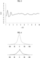
- Fig. 6 shows an example of the spectrum obtained in a case where the solid 7 Li-NMR measurement of the solid electrolyte (I) is performed at 20°C.
- a peak (corresponding to the first peak) is observed in a range of -100 to +100 ppm, and a small peak is observed in the vicinity of a chemical shift of 0 ppm, as shown by the broken line at the first peak.
- it is considered to be affected the fact that a sharp peak is observed in a case where the mobility of Li + is high.
- Fig. 7 shows a diagram in a case where the first peak is waveform-separated.
- the first peak is waveform-separated into a small peak (corresponding to the second peak) represented by the solid line, and a large peak represented by the broken line.
- the above-described second peak is a peak which appears in a range with a chemical shift of -3 to +3 ppm, and has a full-width at half maximum of 5 ppm or less.
- Examples of the method of waveform separation include a method using a known software, and examples of the software include Igor Pro, which is graph processing software manufactured by WaveMetrics, Inc.
- a coefficient of determination which is obtained by performing linear regression analysis according to a least-squares method in a wave number range of 600 to 850 cm -1 in a Raman spectrum of the solid electrolyte (I), is preferably 0.9400 or more and more preferably 0.9600 or more, and also preferably 0.9800 or more.
- the upper limit thereof is not particularly limited, but is usually 1.0000 or less.
- a Raman spectrum of the solid electrolyte (I) is acquired.
- Raman imaging is performed as the measuring method of the Raman spectrum.
- the Raman imaging is a microscopic spectroscopy method which combines Raman spectroscopy with a microscopic technique.
- the Raman imaging is a method of scanning a sample with excitation light to detect measurement light including Raman scattered light, and then visualizing distribution or the like of components based on the intensity of the measurement light.
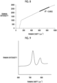
- Fig. 8 shows an example of the Raman spectrum of the solid electrolyte (I).
- the vertical axis indicates the Raman intensity
- the lateral axis indicates the Raman shift.
- a coefficient of determination (coefficient of determination R 2 ) obtained by performing linear regression analysis according to a least-squares method is calculated in a wave number range of 600 to 850 cm -1 of the Raman spectrum shown in Fig. 8 . That is, in a wave number range of 600 to 850 cm -1 in the Raman spectrum of Fig. 8 , a regression line (the thick broken line in Fig. 8 ) is determined according to the least-squares method, and the coefficient of determination R 2 of the regression line is calculated. As the coefficient of determination, a value between 0 (no linear correlation) and 1 (complete linear correlation of the measured values) is taken according to the linear correlation of the measured values.
- Fig. 9 shows a Raman spectrum of a general lithium tetraborate crystal.
- a general lithium tetraborate crystal peaks are observed in a wave number range of 716 to 726 cm -1 and a wave number range of 771 to 785 cm -1 , derived from the structure thereof.
- the coefficient of determination thereof is less than 0.9400 in a case where the coefficient of determination is calculated by performing linear regression analysis according to a least-squares method in a wave number range of 600 to 850 cm -1 .
- the fact that the coefficient of determination is 0.9400 or more means that the solid electrolyte (I) does not substantially include a crystal structure. Therefore, as a result, it is considered that the solid electrolyte (I) has a characteristic of easily undergoing plastic deformation and a characteristic of excellent hopping property of ions such as Li + .
- a value of a ratio of a maximum absorption intensity in a wave number range of 3,000 to 3,500 cm -1 to a maximum absorption intensity in a wave number range of 800 to 1,600 cm -1 is preferably 1/5 or more (0.2 or more).
- the above-described ratio is preferably 3/10 or more and more preferably 2/5 or more.
- the upper limit thereof is not particularly limited, but is preferably 1 or less.
- the measurement is performed using objective lens: Cassegrain type (NA: 0.65) of 32 magnifications, detector: MCT-A, measurement range: 650 to 4,000 cm -1 , resolution: 4 cm -1 , and sample cell: diamond cell.
- objective lens Cassegrain type (NA: 0.65) of 32 magnifications
- detector MCT-A
- measurement range 650 to 4,000 cm -1
- resolution 4 cm -1
- sample cell diamond cell.
- the obtained infrared absorption spectrum is subjected to correction for removing signals derived from water and CO 2 in the air, and the background is further subjected to offset-correction to set the absorption intensity to 0.
- the measurement is performed in the air after vacuum drying at 40°C for 2 hours.
- the solid electrolyte (I) exhibits the following characteristics or physical properties.
- the solid electrolyte (I) is subjected to vacuum drying at 40°C for 2 hours in advance. In addition, the measurement of the mass reduction rate is performed in the air.
- the solid electrolyte layer may contain one or two or more kinds of solid electrolytes.
- a content of the solid electrolyte in the solid electrolyte layer is not particularly limited, and can be set to 100% by mass, but it is preferably 50% to 99.9% by mass, more preferably 70% to 99.5% by mass, and still more preferably 90% to 99% by mass.
- a thickness of the solid electrolyte layer is not particularly limited, and for example, it is preferably 10 to 1,000 ⁇ m, more preferably 20 to 500 ⁇ m, and still more preferably 30 to 100 ⁇ m.
- the type of the solid electrolyte is not particularly limited; and an oxide-based solid electrolyte, a halide-based solid electrolyte, or a hydride-based solid electrolyte can be used, and a sulfide-based solid electrolyte can also be used within a range where the effect of the present invention is not impaired.
- the negative electrode active material layer may contain one or two or more kinds of solid electrolytes.
- a content of the solid electrolyte in the negative electrode active material layer is not particularly limited, and is preferably 50% to 99.9% by mass, more preferably 70% to 99.5% by mass, and still more preferably 90% to 99% by mass, as the total content of the solid electrolyte and the negative electrode active material.
- negative electrode active material itself, a negative electrode active material which can be used for a typical all-solid-state secondary battery can be widely used. A suitable aspect of the negative electrode active material will be described below.
- the negative electrode active material is an active material capable of intercalating and deintercalating an ion of a metal belonging to Group 1 or Group 2 of the periodic table, and an active material capable of reversibly intercalating and deintercalating lithium ions is preferable.
- examples thereof also include various carbon fibers such as PAN-based carbon fiber, cellulose-based carbon fiber, pitch-based carbon fiber, vapor-grown carbon fiber, dehydrated polyvinyl alcohol (PVA)-based carbon fiber, lignin carbon fiber, vitreous carbon fiber, and activated carbon fiber; mesophase microspheres, graphite whisker, and tabular graphite.
- PAN-based carbon fiber cellulose-based carbon fiber
- pitch-based carbon fiber vapor-grown carbon fiber
- PVA dehydrated polyvinyl alcohol
- lignin carbon fiber lignin carbon fiber
- vitreous carbon fiber vitreous carbon fiber
- activated carbon fiber activated carbon fiber
- mesophase microspheres mesophase microspheres
- graphite whisker and tabular graphite.
- the oxide of a metal element or a metalloid element which can be used as the negative electrode active material, is not particularly limited as long as it is an oxide capable of intercalating and deintercalating lithium; and examples thereof include an oxide of a metal element (metal oxide), a composite oxide of a metal element, a composite oxide of a metal element and a metalloid element, and an oxide of a metalloid element (a metalloid oxide).
- the composite oxide of a metal element and the composite oxide of a metal element and a metalloid element are also collectively referred to as a metal composite oxide.
- the highest intensity in a crystalline diffraction line observed in a range of 40° to 70° in terms of the 2 ⁇ value is preferably 100 times or less and more preferably 5 times or less with respect to the intensity of a diffraction line at the apex in a broad scattering band observed in a range of 20° to 40° in terms of the 2 ⁇ value, and it is still more preferable that the oxide does not have a crystalline diffraction line.
- the noncrystalline oxide of a metalloid element or the above-described chalcogenide is more preferable; and a (composite) oxide consisting of one element or a combination of two or more elements selected from elements (for example, Al, Ga, Si, Sn, Ge, Pb, Sb, and Bi) of Group 13 (IIIB) to Group 15 (VB) of the periodic table or the chalcogenide is particularly preferable.
- the noncrystalline oxide and the chalcogenide are preferably Ga 2 O 3 , GeO, PbO, PbO 2 , Pb 2 O 3 , Pb 2 O 4 , Pb 3 O 4 , Sb 2 O 3 , Sb 2 O 4 , Sb 2 O 8 Bi 2 O 3 , Sb 2 O 8 Si 2 O 3 , Sb 2 O 5 , Bi 2 O 3 , Bi 2 O 4 , GeS, PbS, PbS 2 , Sb 2 S 3 , or Sb 2 S 5 .
- metal composite oxide containing lithium examples include a composite oxide of lithium oxide and the above-described metal composite oxide or the above-described chalcogenide. More specific examples thereof include Li 2 SnO 2 .
- the negative electrode active material for example, the metal oxide
- a titanium oxide a titanium oxide
- Li 4 Ti 5 O 12 lithium titanium oxide [LTO]
- LTO lithium titanium oxide
- the lithium alloy as the negative electrode active material is not particularly limited as long as it is typically used as a negative electrode active material for an all-solid-state secondary battery, and examples thereof include a lithium aluminum alloy.
- the silicon element-containing active material examples include a silicon-containing alloy (for example, LaSi 2 , VSi 2 , La-Si, Gd-Si, or Ni-Si) containing a silicon material such as Si and SiOx (0 ⁇ x ⁇ 1) and further containing titanium, vanadium, chromium, manganese, nickel, copper, or lanthanum; and a structured active material thereof (for example, LaSi 2 /Si).
- examples thereof include an active material containing a silicon element and a tin element, such as SnSiO 3 and SnSiS 3 .
- SiOx itself can be used as the negative electrode active material (the metalloid oxide) and Si is produced along with the operation of the all-solid-state secondary battery, SiO x can be used as a negative electrode active material (or a precursor material thereof) capable of forming an alloy with lithium.
- Examples of the negative electrode active material containing a tin element include Sn, SnO, SnO 2 , SnS, SnS 2 , and the above-described active material containing a silicon element and a tin element.
- the volume average particle size is measured according to the following procedure.
- a surface of the negative electrode active material may be coated with an oxide such as another metal oxide and a carbon-based material.
- the surface of the negative electrode active material may be subjected to a surface treatment with sulfur or phosphorus.
- a content of the negative electrode active material in the negative electrode active material layer is not particularly limited, and is preferably 10% to 90% by mass, more preferably 20% to 85% by mass, still more preferably 30% to 80% by mass, and even more preferably 40% to 75% by mass.
- a thickness of the negative electrode active material layer is not particularly limited, and for example, it is preferably 10 to 1,000 ⁇ m, more preferably 20 to 500 ⁇ m, and still more preferably 50 to 300 ⁇ m.
- a functional layer which is appropriately applied to the all-solid-state secondary battery may be provided between the respective layers of the negative electrode collector, the negative electrode active material layer, the solid electrolyte layer, the positive electrode active material layer, and the positive electrode collector, or outside the respective layers; or a member such as a housing or a package may be provided.
- the all-solid-state secondary battery can be manufactured with reference to a general manufacturing method of an all-solid-state secondary battery, except that the above-described oxide-based solid electrolyte (solid electrolyte (I)) is used as the solid electrolyte constituting the active material layer containing an active material as a recovery target. That is, the manufacturing of an all-solid-state secondary battery can be performed by including a step of obtaining a laminate in which a positive electrode active material layer, a solid electrolyte layer, and a negative electrode active material layer are arranged in this order.
- an amount of water used in the solid electrolyte (I) may satisfy or not satisfy the amount specified in the present invention.
- the amount of water used in the solid electrolyte (I) is not regarded; but in order to set the amount of water of the solid electrolyte (I) contained in the constitutional layer such as the active material layer to the amount specified in the present invention, a step of subjecting the formed constitutional layer to a drying treatment can also be included as necessary.
- the drying step of the constitutional layer may be performed at any stage after the constitutional layer is formed, as long as the solid electrolyte (I) of the constitutional layer in the secondary battery to be obtained can be set to the water amount specified in the present invention.
- the drying treatment is not particularly limited, and for example, the water amount of the solid electrolyte (I) in the constitutional layer can be reduced to within the range specified in the present invention by using a desiccator, subjecting the constitutional layer to vacuum drying, subjecting the constitutional layer to freeze vacuum drying, or subjecting the constitutional layer to a heating treatment.
- the all-solid-state secondary battery is preferably a battery obtained by sealing a laminate in which the positive electrode collector, the positive electrode active material layer, the solid electrolyte layer, the negative electrode active material layer, and the negative electrode collector are arranged in this order.
- the sealing method is not particularly limited as long as the mixing of moisture (atmosphere) can be blocked or suppressed. Examples thereof include a method of sealing the above-described laminate by closing a lid of a housing (battery cell) storing the laminate using a gasket such as an O-ring.
- cell resistance can also be improved by heating the obtained laminate (for example, at 80°C for 2 hours).
- a method of forming the laminate in which the positive electrode collector, the positive electrode active material layer, the solid electrolyte layer, the negative electrode active material layer, and the negative electrode collector are arranged in this order is not particularly limited; and examples of a method of forming each of the constitutional layers include formation by applying a dispersion liquid and powder compaction molding.
- Examples of one aspect of the manufacturing method of an all-solid-state secondary battery include a manufacturing method including applying a dispersion liquid of the solid electrolyte (I) to form a constitutional layer, particularly an active material layer. Since the solid electrolyte (I) can be easily prepared as an aqueous dispersion liquid (solid electrolyte slurry), the method can be adopted. Specifically, the positive electrode active material layer and the negative electrode active material layer can be formed by applying a dispersion liquid of the active material and the solid electrolyte (I), respectively. In a case where other components such as the conductive auxiliary agent are contained as components other than the active material, a dispersion liquid in which these components are also dispersed is used.
- a dispersion medium in the dispersion liquid of the solid electrolyte (I) and the dispersion liquid of the active material can be appropriately selected in consideration of reactivity with the components contained in the dispersion liquid.
- the dispersion liquid of the solid electrolyte (I) it is preferable to use an aqueous dispersion liquid; and in a case of containing the sulfide-based solid electrolyte, it is preferable to use a dispersion system of an organic solvent.
- Examples of the manufacturing method of the all-solid-state secondary battery include a method in which a composition for forming a positive electrode (positive electrode slurry) containing a positive electrode active material is applied onto a metal foil which is a positive electrode collector to form a positive electrode active material layer, a dispersion liquid for forming a solid electrolyte layer (solid electrolyte slurry) containing a solid electrolyte is applied onto the positive electrode active material layer to form a solid electrolyte layer, a composition for forming a negative electrode (negative electrode slurry) containing a negative electrode active material is applied onto the solid electrolyte layer to form a negative electrode active material layer, and a negative electrode collector (metal foil) is laminated on the negative electrode active material layer.
- a composition for forming a positive electrode (positive electrode slurry) containing a positive electrode active material is applied onto a metal foil which is a positive electrode collector to form a positive electrode active material layer
- the entire laminate is optionally subjected to a pressurization treatment to obtain the all-solid-state secondary battery as shown in Fig. 1 .
- the all-solid-state secondary battery can also be manufactured by reversing the method of forming each layer, which includes forming the negative electrode active material layer, the solid electrolyte layer, and the positive electrode active material layer on the negative electrode collector, and optionally subjecting the entire laminate to a pressurization treatment.
- the solid electrolyte (I) is contained in the composition containing an active material to be recovered, and is contained in, for example, at least one of the composition for forming a positive electrode or the composition for forming a negative electrode, and may be further contained in a dispersion liquid for forming a solid electrolyte layer.
- the all-solid-state secondary battery can also be manufactured by separately producing the positive electrode active material layer, the solid electrolyte layer, and the negative electrode active material layer, laminating these layers, and optionally pressurizing the laminate.
- a support such as a nonwoven fabric may be disposed as necessary, and each layer can be made into a self-supporting film.
- the positive electrode active material layer and the negative electrode active material layer can be formed by pressure-molding powder constituting each layer (the active material, solid electrolyte (I), and other components).
- the method of preparing the powder of the negative electrode mixture is not particularly limited, and the powder of the negative electrode mixture can be prepared, for example, by mixing the powder of the solid electrolyte prepared in advance with a component for forming the negative electrode active material layer containing a negative electrode active material.
- the all-solid-state secondary battery is initialized after manufacturing or before use.
- the initialization method is not particularly limited, and it is possible to initialize the all-solid-state secondary battery by, for example, performing initial charging and discharging in a state in which a pressing pressure is increased and then releasing the pressure until the pressure falls within the range of the pressure condition at the time of using the all-solid-state secondary battery.
- the aqueous medium used in the contact step is a medium containing water, and may contain a hydrophilic solvent or a water-soluble solvent in addition to the water.
- the water is not particularly limited, and (ultra)pure water, ion exchange water, or the like can be used.
- the hydrophilic solvent or the water-soluble solvent include alcohol solvents such as methanol and ethanol, ketone solvents such as acetone and methyl ethyl ketone, polyhydric alcohol solvents such as diethylene glycol and glycerin, and ether solvents such as propylene glycol monomethyl ether, dipropylene glycol monomethyl ether, diethylene glycol monoethyl ether, and diethylene glycol monobutyl ether.
- a content of the water-soluble solvent in the aqueous medium is not particularly limited, but is preferably 50% by mass or less.
- water is preferably used.
- An amount of the aqueous medium used for the all-solid-state secondary battery member is not unambiguously determined by the difference in the contact method.
- a concentration of the oxide-based solid electrolyte can be set to 10% by mass or less, and preferably 5% by mass or less.
- the amount of the aqueous medium used with respect to 1 g of the all-solid-state secondary battery member can be, for example, 10 g or more, preferably 20 g or more. More specifically, in the immersion method, the amount of the aqueous medium used is more preferably 100 to 1,000 g and still more preferably 10 to 100 g with respect to 1 g of the all-solid-state secondary battery member.
- the treated liquid obtained in the contact step is subjected to solid-liquid separation.
- the representative "solid-liquid separation” is described as a method of separating the aqueous medium and an insoluble component in the treated liquid, but in the present invention, the "solid-liquid separation” is not limited as long as the aqueous medium and the insoluble component can be separated.
- an insoluble component such as the active material dispersed in the treated liquid can be separated from a liquid component such as the aqueous medium, specifically, a dissolved component such as the oxide-based solid electrolyte (and other components) dissolved in the treated liquid.
- a solid-liquid separation method As a solid-liquid separation method, a general solid-liquid separation method can be applied without particular limitation. From the viewpoint of workability, a filtration method is preferable. Examples of the filtration method include a natural filtration method, a reduced pressure filtration method (suction filtration method), a pressurized filtration method, and a centrifugal filtration method; and various filtration devices can be used.
- Ultrafiltration conditions at this time cannot be unambiguously determined depending on the density of the two active materials to be separated, and can be appropriately set in consideration of the difference in density, and the like.
- a rotation speed can be set to 2,000 to 150,000 rpm
- a treatment time can be set to 1 to 20 minutes.
- the method according to the embodiment of the present invention may include a step other than the above-described steps (referred to as "other steps").
- the other steps are not particularly limited, and examples thereof include, as a pre-treatment step, a step of charging or discharging the all-solid-state secondary battery, a step of removing a housing, a package, or the like from the all-solid-state secondary battery, a step of obtaining the all-solid-state secondary battery member by disassembling, crushing, or the like the all-solid-state secondary battery, and a step of peeling off the collector from the all-solid-state secondary battery member.
- examples thereof include, as a post-treatment step, a step of purifying the recovered product, a step of washing the recovered product, a step of drying the recovered product, a step of pulverizing or crushing the recovered product, and a step of classifying the recovered product.
- a step of purifying the recovered product for example, a recrystallization method, a reprecipitation method, a method using column chromatography, a method of removing an organic substance, and the like can be applied.
- the recovered product obtained by the method according to the embodiment of the present invention contains a positive electrode active material and a negative electrode active material, and further contains a solid component such as a conductive auxiliary agent
- a step of isolating the target active material from the recovered product can also be performed as a step different from the solid-liquid separation step.
- an appropriate method can be applied depending on the type, characteristics, and the like of each component contained in the recovered product. From the viewpoint that it is possible to isolate with high purity and favorable workability, an isolation method (classification method) using a difference in specific gravity of the respective components is preferable; and specific examples thereof include a centrifugal separation method, an air separation method, and a sedimentation separation method.
- the coefficient of determination obtained by performing linear regression analysis according to a least-squares method in a wave number range of 600 to 850 cm -1 was 0.9974.
- the mass reduction rate of the solid electrolyte (I)-1 in a case of being heated from 25°C to 800°C as described above was 29.8%.
- the obtained dispersion liquid was transferred to a glass petri dish, and dried at 120°C for 2 hours in the air to obtain a film of solid electrolyte. Subsequently, the obtained film was peeled off to obtain a powdery solid electrolyte (I)-2.
- Various evaluations were performed on the solid electrolyte (I)-2 in the air in the same manner as in Reference Example 1. The results are summarized in the tables below.
- the obtained fine substance of the lithium-containing oxide was added to water such that a concentration of the fine substance was 42% by mass, and the mixture was subjected to ultrasonic dispersion for 60 minutes to obtain a dispersion liquid 1.
- LiFSI chemical formula: Li(FSO 2 ) 2 N
- a dispersion liquid 3 was obtained in the same manner as in the preparation of the dispersion liquid 1 in Reference Example 3.
- LiFSI chemical formula: Li(FSO 2 ) 2 N
- a dispersion liquid 5 was obtained in the same manner as in the preparation of the dispersion liquid 1 in Reference Example 3.
- the obtained dispersion liquid 5 and solution 6 were mixed, and stirred and mixed with a magnetic stirrer for 60 minutes. Subsequently, the obtained dispersion liquid was vacuum-dried at 40°C and 10 Pa for 15 hours to obtain a powdery solid electrolyte (I)-5.
- Various evaluations were performed in the air in the same manner as in Reference Example 1 using the obtained powdery solid electrolyte (I)-5 as soon as possible. The results are summarized in the tables below.
- Fig. 10 shows the reduced pair distribution function G(r) obtained from the LBO powder.
- compact powder body R1 for comparative reference.
- the ion conductivity of the obtained compacted powder body R1 was 7.5 ⁇ 10 -9 S/cm at 27°C and 7.5 ⁇ 10 -8 S/cm at 60°C.
- Proportion of area intensity is a proportion of the area intensity of the second peak to the area intensity of the first peak in the above-described solid 7 Li-NMR measurement, and the evaluation results based on the following standards are described.
- LiTFSI chemical formula: Li(F 3 CSO 2 ) 2 N
- a concentration was 87% by mass
- the obtained dispersion liquid 9 and solution 10 were mixed, and stirred and mixed with a magnetic stirrer for 60 minutes. Subsequently, the obtained dispersion liquid was vacuum-dried at 40°C and 10 Pa for 15 hours to obtain a powdery solid electrolyte (I)-7. The obtained powder was allowed to stand in the air for a certain period of time, and various evaluations were performed in the air in the same manner as in Reference Example 1 using the solid electrolyte (I)-7. The results are summarized in the tables below.
- a solid electrolyte (I)-8 was obtained in the same manner as in Reference Example 7, except that the content of water and LiTFSI in the obtained solid electrolyte (I) was changed to the amount shown in the table below; and various evaluations were performed in the air in the same manner as in Reference Example 1. The results are summarized in the tables below.
- the solid electrolyte of each of Reference Examples satisfied the composition specified in the claim 1 of the present application, had desired characteristics or physical properties, and exhibited excellent ion conductivity.
- a solid electrolyte having a specific composition specified in claim 1 was prepared separately from Reference Examples 1 to 13, and the recovery of the active material from the all-solid-state secondary battery using the solid electrolyte was attempted.
- the solid electrolyte slurry was vacuum-dried at 40°C and 20 Pa for 15 hours to obtain a powder. After storing the obtained powder in a desiccator (humidity: 5%) for several days and then analyzing in the air, it was confirmed that the powder had the above-described X-ray diffraction characteristics and was in an amorphous state. In addition, in a case where the ion conductivity was measured by the above-described method, the ion conductivity was 4.5 ⁇ 10 -3 S/cm.
- the value of the ratio of the content of LiFSI to the content of the lithium-containing oxide was 1 in terms of a molar ratio; and the value of the ratio of the content of water to the content of the lithium-containing oxide was 9 in terms of a molar ratio.
- LiCoO 2 LiCoO 2
- CNT carbon nanotubes
- TiNb 2 O 7 TiNb 2 O 7
- CNT carbon nanotubes
- the above-described positive electrode slurry was applied onto an A4-sized Al foil having a thickness of 50 ⁇ m using a desktop coating machine at an applicator gap of 100 ⁇ m and an application speed of 30 mm/s. After being left to stand at room temperature for 1 hour, the above-described solid electrolyte slurry was applied onto a positive electrode slurry coating film in a multilayer manner using a desktop coating machine at an applicator gap of 200 ⁇ m and a coating rate of 90 mm/s.
- the multilayer coating film was stored in a desiccator having a relative humidity of 5% or less for 12 hours and dried, and punched with a hand punch to have a diameter of 10 mm, thereby obtaining a positive electrode-side laminate (solid electrolyte layer/positive electrode active material layer/Al collector).
- the above-described negative electrode slurry was applied onto an A4-sized Al foil having a thickness of 50 ⁇ m using a desktop coating machine at an applicator gap of 200 ⁇ m and an application speed of 30 mm/s. After being left to stand at room temperature for 1 hour, the above-described solid electrolyte slurry was applied onto a negative electrode slurry coating film in a multilayer manner using a desktop coating machine at an applicator gap of 300 ⁇ m and a coating rate of 90 mm/s.
- the multilayer coating film was stored in a desiccator having a relative humidity of 5% or less for 12 hours and dried, and punched with a hand punch to have a diameter of 10 mm, thereby obtaining a negative electrode-side laminate (solid electrolyte layer/negative electrode active material layer/Al collector).
- the above-described negative electrode-side laminate was placed on a 10 mm-diameter SUS base of an all-solid-state battery evaluation cell (product name: KP-SolidCell) manufactured by Hohsen Corp. with the solid electrolyte layer side facing upward, and the positive electrode-side laminate obtained above was further placed thereon with the solid electrolyte layer side facing downward.
- a laminate having a structure of positive electrode-side laminate/negative electrode-side laminate (this laminate is referred to as a cell) was obtained.
- one particle of silica gel for water removal was placed in the cavity of the KP-SolidCell, and the upper housing of the KP-SolidCell was fitted and sealed using a double O-ring, a 4-point bolt, and a butterfly nut.
- the cell was restrained from above and below by a restraining pressure applying mechanism provided on the upper part of the KP-SolidCell at a torque of 5 Nm (corresponding to 30 MPa).
- a treated liquid obtained by bringing the positive electrode laminate into contact with water was subjected to suction filtration using a filter paper (manufactured by Whatman International Ltd.) having a particle retention capacity smaller than the volume average particle size (particle size distribution) of LCO, and the filter cake was washed with ultrapure water to obtain LCO.
- the filter paper used was a filter paper which allowed CNT to pass through. The filter cake was dried in an electric furnace set to 120°C for 2 hours together with the filter paper, thereby recovering 8.7 mg of LCO.
- a treated liquid obtained by bringing the negative electrode laminate into contact with water was subjected to suction filtration using a filter paper (manufactured by Whatman International Ltd.) having a particle retention capacity smaller than the volume average particle size (particle size distribution) of TNO, and the filter cake was washed with ultrapure water to obtain TNO.
- the filter paper used was a filter paper which allowed CNT to pass through. The filter cake was dried in an electric furnace set to 120°C for 2 hours together with the filter paper, thereby recovering 5.9 mg of TNO.
- Recovery rate of TNO Amount of TNO recovered g / TNO content in negative electrode active material layer g ⁇ 100 %
- the active materials LCO and TNO could be recovered with a high recovery rate of 90% by mass or more, by a simple operation of bringing the positive electrode laminate or the negative electrode laminate into contact with water and then performing the solid-liquid separation.
- the LCO and TNO recovered in this way had a purity that could be used as an active material layer of the all-solid-state secondary battery.
- the filtrate obtained in the solid-liquid separation step contained an oxide-based solid electrolyte, and the oxide-based solid electrolyte (the above-described lithium-containing oxide and lithium salt) could also be recovered from each filtrate as necessary.
- the all-solid-state secondary battery produced in Production Example 1 was charged in an environment of 25°C at a current density of 0.8 mA/cm 2 until the battery voltage reached 2.8 V, and then discharged at a current density of 0.8 mA/cm 2 until the battery voltage reached 1.5 V.
- One charging operation and one discharging operation described above were set as one cycle of charging and discharging, and 100 cycles of charging and discharging were repeated under the same conditions.
- Example 2 the positive electrode laminate and the negative electrode laminate obtained from the all-solid-state secondary battery were subjected to a method of being separated and recovered, but the all-solid-state secondary battery itself could also be subjected to the method of being separated and recovered.
- the treated liquid obtained in the contact step could be subjected to, for example, a centrifugal separation treatment or the like, and two active materials could be separated by using a difference in density between the positive electrode active material and the negative electrode active material.
- the two active materials could be recovered with a high recovery rate by separating each of the two active materials from the other active material at the same time as the oxide-based solid electrolyte.
Landscapes
- Chemical & Material Sciences (AREA)
- Organic Chemistry (AREA)
- Engineering & Computer Science (AREA)
- Manufacturing & Machinery (AREA)
- Inorganic Chemistry (AREA)
- Life Sciences & Earth Sciences (AREA)
- Electrochemistry (AREA)
- General Chemical & Material Sciences (AREA)
- Chemical Kinetics & Catalysis (AREA)
- Environmental & Geological Engineering (AREA)
- General Life Sciences & Earth Sciences (AREA)
- Geology (AREA)
- Materials Engineering (AREA)
- Mechanical Engineering (AREA)
- Metallurgy (AREA)
- Secondary Cells (AREA)
Applications Claiming Priority (3)
| Application Number | Priority Date | Filing Date | Title |
|---|---|---|---|
| JP2022089966 | 2022-06-01 | ||
| JP2022197051 | 2022-12-09 | ||
| PCT/JP2023/020301 WO2023234357A1 (ja) | 2022-06-01 | 2023-05-31 | 活物質の回収方法 |
Publications (2)
| Publication Number | Publication Date |
|---|---|
| EP4535508A1 true EP4535508A1 (de) | 2025-04-09 |
| EP4535508A4 EP4535508A4 (de) | 2025-12-17 |
Family
ID=89024915
Family Applications (1)
| Application Number | Title | Priority Date | Filing Date |
|---|---|---|---|
| EP23816114.5A Pending EP4535508A4 (de) | 2022-06-01 | 2023-05-31 | Verfahren zur rückgewinnung von aktivem material |
Country Status (5)
| Country | Link |
|---|---|
| US (1) | US20250091901A1 (de) |
| EP (1) | EP4535508A4 (de) |
| JP (1) | JPWO2023234357A1 (de) |
| CN (1) | CN119054133A (de) |
| WO (1) | WO2023234357A1 (de) |
Family Cites Families (15)
| Publication number | Priority date | Publication date | Assignee | Title |
|---|---|---|---|---|
| JPS6029550U (ja) | 1983-08-05 | 1985-02-28 | 株式会社 伊藤喜工作所 | 陳列装置用支柱の連結装置 |
| JPH0345473Y2 (de) | 1984-10-25 | 1991-09-26 | ||
| JPH0619351B2 (ja) | 1985-07-23 | 1994-03-16 | 和光純薬工業株式会社 | ラテツクス凝集反応測定装置 |
| JPH026856A (ja) | 1988-06-27 | 1990-01-11 | Motonobu Shibata | 触媒担体およびその製造方法 |
| JPH064516Y2 (ja) | 1989-06-26 | 1994-02-02 | 日本開閉器工業株式会社 | ロータリスイッチ |
| JPH0345473A (ja) | 1989-07-11 | 1991-02-27 | Toyoda Mach Works Ltd | 四輪操舵装置 |
| JPH0590844A (ja) | 1991-09-26 | 1993-04-09 | Toshiba Corp | 歪補償器 |
| JPH064516A (ja) | 1992-06-17 | 1994-01-14 | Toshiba Corp | 割当て決定支援方式 |
| JP5062262B2 (ja) | 2009-03-16 | 2012-10-31 | トヨタ自動車株式会社 | 電池部材の処理方法 |
| JP2016033876A (ja) | 2014-07-31 | 2016-03-10 | トヨタ自動車株式会社 | 正極活物質成分の回収方法 |
| JP6423300B2 (ja) * | 2015-03-27 | 2018-11-14 | Jx金属株式会社 | 固体酸化物形燃料電池スクラップからのイットリウムとニッケルの分離回収方法 |
| EP3643690A4 (de) | 2017-06-23 | 2021-03-17 | AGC Inc. | Optisches glas und optische komponente |
| JP7415352B2 (ja) * | 2019-07-17 | 2024-01-17 | 住友金属鉱山株式会社 | リチウムイオン二次電池の再生方法 |
| KR20220109449A (ko) * | 2020-02-07 | 2022-08-04 | 후지필름 가부시키가이샤 | 무기 고체 전해질 함유 조성물, 전고체 이차 전지용 시트 및 전고체 이차 전지 및, 전고체 이차 전지용 시트 및 전고체 이차 전지의 제조 방법 |
| EP4001213A1 (de) * | 2020-11-13 | 2022-05-25 | Samsung Electronics Co., Ltd. | Oxid, verfahren zur herstellung davon, fester elektrolyt mit dem oxid und elektrochemische vorrichtung mit dem oxid |
-
2023
- 2023-05-31 EP EP23816114.5A patent/EP4535508A4/de active Pending
- 2023-05-31 WO PCT/JP2023/020301 patent/WO2023234357A1/ja not_active Ceased
- 2023-05-31 JP JP2024524915A patent/JPWO2023234357A1/ja active Pending
- 2023-05-31 CN CN202380035183.8A patent/CN119054133A/zh active Pending
-
2024
- 2024-11-28 US US18/963,545 patent/US20250091901A1/en active Pending
Also Published As
| Publication number | Publication date |
|---|---|
| EP4535508A4 (de) | 2025-12-17 |
| JPWO2023234357A1 (de) | 2023-12-07 |
| US20250091901A1 (en) | 2025-03-20 |
| CN119054133A (zh) | 2024-11-29 |
| WO2023234357A1 (ja) | 2023-12-07 |
Similar Documents
| Publication | Publication Date | Title |
|---|---|---|
| KR102366885B1 (ko) | 리튬 이온 2 차 전지 | |
| KR102884163B1 (ko) | 리튬계 고체 전해질, 무기 고체 전해질, 리튬계 고체 전해질의 제조 방법, 수식 정극 활물질, 수식 부극 활물질, 전고체 이차 전지, 전고체 이차 전지용 전극 시트, 고체 전해질 시트, 전고체 이차 전지용 전극 | |
| EP3089254B1 (de) | Festkörperlithiumbatterie, festkörperlithiumbatteriemodul und verfahren zur herstellung einer festkörperlithiumbatterie | |
| EP4455080A1 (de) | Phosphor-kohlenstoff-verbundmaterial, herstellungsverfahren für phosphor-kohlenstoff-verbundmaterial, negativelektrodenaktivmaterial, negativelektrode für lithiumsekundärbatterie und lithiumsekundärbatterie | |
| US20230327192A1 (en) | Oxide solid electrolyte, binder, solid electrolyte layer, active material, electrode, all-solid state secondary battery | |
| EP4451385A1 (de) | Positivelektrodenmaterialzusammensetzung und herstellungsverfahren dafür, positivelektrodenplatte damit, sekundärbatterie und elektrische vorrichtung | |
| WO2023234351A1 (ja) | 全固体リチウムイオン二次電池及び全固体リチウムイオン二次電池の製造方法 | |
| US20250096317A1 (en) | All-solid-state lithium ion secondary battery and manufacturing method of all-solid-state lithium ion secondary battery | |
| US20250096244A1 (en) | Electrode composition for all-solid-state secondary battery, electrode sheet for all-solid-state secondary battery, all-solid-state secondary battery, and manufacturing method of electrode sheet for all-solid-state secondary battery, and manufacturing method of all-solid-state secondary battery | |
| US20250096316A1 (en) | Wound-type all-solid-state lithium ion secondary battery and manufacturing method of wound-type all-solid-state lithium ion secondary battery | |
| US20250096318A1 (en) | Electrode composition for all-solid-state secondary battery, electrode sheet for all-solid-state secondary battery, all-solid-state secondary battery, and manufacturing method of electrode sheet for all-solid-state secondary battery, and manufacturing method of all-solid-state secondary battery | |
| EP4535485A1 (de) | Lithium-festelektrolyt, verfahren zur herstellung des lithium-festelektrolyten, modifiziertes positivelektrodenaktivmaterial, festkörper-sekundärbatterie | |
| EP4535508A1 (de) | Verfahren zur rückgewinnung von aktivem material | |
| EP4535481A1 (de) | Lithium-ionen-festkörpersekundärbatterie und verfahren zur herstellung einer lithium-ionen-festkörpersekundärbatterie | |
| KR102924446B1 (ko) | 전극 활물질, 전극 합재, 전극층, 전지, 및, 이들의 제조 방법 | |
| CN121439697A (zh) | 电极层和电池 | |
| KR20250103460A (ko) | 전극 활물질, 전극 합재, 전극층, 전지, 및, 이들의 제조 방법 | |
| Berti | MgH2-TiH2 hydrides as negative electrodesof Li-ion batteries | |
| CN121439698A (zh) | 电极层和电池 | |
| CN115084498A (zh) | 活性物质、电极、二次电池、电池包及车辆 |
Legal Events
| Date | Code | Title | Description |
|---|---|---|---|
| STAA | Information on the status of an ep patent application or granted ep patent |
Free format text: STATUS: THE INTERNATIONAL PUBLICATION HAS BEEN MADE |
|
| PUAI | Public reference made under article 153(3) epc to a published international application that has entered the european phase |
Free format text: ORIGINAL CODE: 0009012 |
|
| STAA | Information on the status of an ep patent application or granted ep patent |
Free format text: STATUS: REQUEST FOR EXAMINATION WAS MADE |
|
| 17P | Request for examination filed |
Effective date: 20241014 |
|
| AK | Designated contracting states |
Kind code of ref document: A1 Designated state(s): AL AT BE BG CH CY CZ DE DK EE ES FI FR GB GR HR HU IE IS IT LI LT LU LV MC ME MK MT NL NO PL PT RO RS SE SI SK SM TR |
|
| DAV | Request for validation of the european patent (deleted) | ||
| DAX | Request for extension of the european patent (deleted) | ||
| A4 | Supplementary search report drawn up and despatched |
Effective date: 20251117 |
|
| RIC1 | Information provided on ipc code assigned before grant |
Ipc: H01M 10/54 20060101AFI20251111BHEP Ipc: H01M 10/36 20100101ALI20251111BHEP Ipc: C01B 35/12 20060101ALI20251111BHEP Ipc: C22B 7/00 20060101ALI20251111BHEP |