EP4451385A1 - Positivelektrodenmaterialzusammensetzung und herstellungsverfahren dafür, positivelektrodenplatte damit, sekundärbatterie und elektrische vorrichtung - Google Patents
Positivelektrodenmaterialzusammensetzung und herstellungsverfahren dafür, positivelektrodenplatte damit, sekundärbatterie und elektrische vorrichtung Download PDFInfo
- Publication number
- EP4451385A1 EP4451385A1 EP22947445.7A EP22947445A EP4451385A1 EP 4451385 A1 EP4451385 A1 EP 4451385A1 EP 22947445 A EP22947445 A EP 22947445A EP 4451385 A1 EP4451385 A1 EP 4451385A1
- Authority
- EP
- European Patent Office
- Prior art keywords
- positive electrode
- optionally
- cladding layer
- groups
- core
- Prior art date
- Legal status (The legal status is an assumption and is not a legal conclusion. Google has not performed a legal analysis and makes no representation as to the accuracy of the status listed.)
- Pending
Links
Images
Classifications
-
- H—ELECTRICITY
- H01—ELECTRIC ELEMENTS
- H01M—PROCESSES OR MEANS, e.g. BATTERIES, FOR THE DIRECT CONVERSION OF CHEMICAL ENERGY INTO ELECTRICAL ENERGY
- H01M4/00—Electrodes
- H01M4/02—Electrodes composed of, or comprising, active material
- H01M4/36—Selection of substances as active materials, active masses, active liquids
- H01M4/362—Composites
- H01M4/366—Composites as layered products
-
- H—ELECTRICITY
- H01—ELECTRIC ELEMENTS
- H01M—PROCESSES OR MEANS, e.g. BATTERIES, FOR THE DIRECT CONVERSION OF CHEMICAL ENERGY INTO ELECTRICAL ENERGY
- H01M10/00—Secondary cells; Manufacture thereof
- H01M10/05—Accumulators with non-aqueous electrolyte
- H01M10/052—Li-accumulators
- H01M10/0525—Rocking-chair batteries, i.e. batteries with lithium insertion or intercalation in both electrodes; Lithium-ion batteries
-
- H—ELECTRICITY
- H01—ELECTRIC ELEMENTS
- H01M—PROCESSES OR MEANS, e.g. BATTERIES, FOR THE DIRECT CONVERSION OF CHEMICAL ENERGY INTO ELECTRICAL ENERGY
- H01M10/00—Secondary cells; Manufacture thereof
- H01M10/05—Accumulators with non-aqueous electrolyte
- H01M10/052—Li-accumulators
-
- H—ELECTRICITY
- H01—ELECTRIC ELEMENTS
- H01M—PROCESSES OR MEANS, e.g. BATTERIES, FOR THE DIRECT CONVERSION OF CHEMICAL ENERGY INTO ELECTRICAL ENERGY
- H01M10/00—Secondary cells; Manufacture thereof
- H01M10/42—Methods or arrangements for servicing or maintenance of secondary cells or secondary half-cells
- H01M10/4235—Safety or regulating additives or arrangements in electrodes, separators or electrolyte
-
- H—ELECTRICITY
- H01—ELECTRIC ELEMENTS
- H01M—PROCESSES OR MEANS, e.g. BATTERIES, FOR THE DIRECT CONVERSION OF CHEMICAL ENERGY INTO ELECTRICAL ENERGY
- H01M4/00—Electrodes
- H01M4/02—Electrodes composed of, or comprising, active material
- H01M4/13—Electrodes for accumulators with non-aqueous electrolyte, e.g. for lithium-accumulators; Processes of manufacture thereof
- H01M4/131—Electrodes based on mixed oxides or hydroxides, or on mixtures of oxides or hydroxides, e.g. LiCoOx
-
- H—ELECTRICITY
- H01—ELECTRIC ELEMENTS
- H01M—PROCESSES OR MEANS, e.g. BATTERIES, FOR THE DIRECT CONVERSION OF CHEMICAL ENERGY INTO ELECTRICAL ENERGY
- H01M4/00—Electrodes
- H01M4/02—Electrodes composed of, or comprising, active material
- H01M4/13—Electrodes for accumulators with non-aqueous electrolyte, e.g. for lithium-accumulators; Processes of manufacture thereof
- H01M4/136—Electrodes based on inorganic compounds other than oxides or hydroxides, e.g. sulfides, selenides, tellurides, halogenides or LiCoFy
-
- H—ELECTRICITY
- H01—ELECTRIC ELEMENTS
- H01M—PROCESSES OR MEANS, e.g. BATTERIES, FOR THE DIRECT CONVERSION OF CHEMICAL ENERGY INTO ELECTRICAL ENERGY
- H01M4/00—Electrodes
- H01M4/02—Electrodes composed of, or comprising, active material
- H01M4/13—Electrodes for accumulators with non-aqueous electrolyte, e.g. for lithium-accumulators; Processes of manufacture thereof
- H01M4/139—Processes of manufacture
- H01M4/1397—Processes of manufacture of electrodes based on inorganic compounds other than oxides or hydroxides, e.g. sulfides, selenides, tellurides, halogenides or LiCoFy
-
- H—ELECTRICITY
- H01—ELECTRIC ELEMENTS
- H01M—PROCESSES OR MEANS, e.g. BATTERIES, FOR THE DIRECT CONVERSION OF CHEMICAL ENERGY INTO ELECTRICAL ENERGY
- H01M4/00—Electrodes
- H01M4/02—Electrodes composed of, or comprising, active material
- H01M4/36—Selection of substances as active materials, active masses, active liquids
- H01M4/48—Selection of substances as active materials, active masses, active liquids of inorganic oxides or hydroxides
- H01M4/50—Selection of substances as active materials, active masses, active liquids of inorganic oxides or hydroxides of manganese
- H01M4/505—Selection of substances as active materials, active masses, active liquids of inorganic oxides or hydroxides of manganese of mixed oxides or hydroxides containing manganese for inserting or intercalating light metals, e.g. LiMn2O4 or LiMn2OxFy
-
- H—ELECTRICITY
- H01—ELECTRIC ELEMENTS
- H01M—PROCESSES OR MEANS, e.g. BATTERIES, FOR THE DIRECT CONVERSION OF CHEMICAL ENERGY INTO ELECTRICAL ENERGY
- H01M4/00—Electrodes
- H01M4/02—Electrodes composed of, or comprising, active material
- H01M4/36—Selection of substances as active materials, active masses, active liquids
- H01M4/48—Selection of substances as active materials, active masses, active liquids of inorganic oxides or hydroxides
- H01M4/52—Selection of substances as active materials, active masses, active liquids of inorganic oxides or hydroxides of nickel, cobalt or iron
- H01M4/525—Selection of substances as active materials, active masses, active liquids of inorganic oxides or hydroxides of nickel, cobalt or iron of mixed oxides or hydroxides containing iron, cobalt or nickel for inserting or intercalating light metals, e.g. LiNiO2, LiCoO2 or LiCoOxFy
-
- H—ELECTRICITY
- H01—ELECTRIC ELEMENTS
- H01M—PROCESSES OR MEANS, e.g. BATTERIES, FOR THE DIRECT CONVERSION OF CHEMICAL ENERGY INTO ELECTRICAL ENERGY
- H01M4/00—Electrodes
- H01M4/02—Electrodes composed of, or comprising, active material
- H01M4/36—Selection of substances as active materials, active masses, active liquids
- H01M4/58—Selection of substances as active materials, active masses, active liquids of inorganic compounds other than oxides or hydroxides, e.g. sulfides, selenides, tellurides, halogenides or LiCoFy; of polyanionic structures, e.g. phosphates, silicates or borates
- H01M4/5825—Oxygenated metallic salts or polyanionic structures, e.g. borates, phosphates, silicates, olivines
-
- H—ELECTRICITY
- H01—ELECTRIC ELEMENTS
- H01M—PROCESSES OR MEANS, e.g. BATTERIES, FOR THE DIRECT CONVERSION OF CHEMICAL ENERGY INTO ELECTRICAL ENERGY
- H01M4/00—Electrodes
- H01M4/02—Electrodes composed of, or comprising, active material
- H01M4/62—Selection of inactive substances as ingredients for active masses, e.g. binders, fillers
- H01M4/624—Electric conductive fillers
- H01M4/625—Carbon or graphite
-
- H—ELECTRICITY
- H01—ELECTRIC ELEMENTS
- H01M—PROCESSES OR MEANS, e.g. BATTERIES, FOR THE DIRECT CONVERSION OF CHEMICAL ENERGY INTO ELECTRICAL ENERGY
- H01M4/00—Electrodes
- H01M4/02—Electrodes composed of, or comprising, active material
- H01M4/62—Selection of inactive substances as ingredients for active masses, e.g. binders, fillers
- H01M4/628—Inhibitors, e.g. gassing inhibitors, corrosion inhibitors
-
- H—ELECTRICITY
- H01—ELECTRIC ELEMENTS
- H01M—PROCESSES OR MEANS, e.g. BATTERIES, FOR THE DIRECT CONVERSION OF CHEMICAL ENERGY INTO ELECTRICAL ENERGY
- H01M4/00—Electrodes
- H01M4/02—Electrodes composed of, or comprising, active material
- H01M2004/021—Physical characteristics, e.g. porosity, surface area
-
- H—ELECTRICITY
- H01—ELECTRIC ELEMENTS
- H01M—PROCESSES OR MEANS, e.g. BATTERIES, FOR THE DIRECT CONVERSION OF CHEMICAL ENERGY INTO ELECTRICAL ENERGY
- H01M4/00—Electrodes
- H01M4/02—Electrodes composed of, or comprising, active material
- H01M2004/026—Electrodes composed of, or comprising, active material characterised by the polarity
- H01M2004/028—Positive electrodes
-
- Y—GENERAL TAGGING OF NEW TECHNOLOGICAL DEVELOPMENTS; GENERAL TAGGING OF CROSS-SECTIONAL TECHNOLOGIES SPANNING OVER SEVERAL SECTIONS OF THE IPC; TECHNICAL SUBJECTS COVERED BY FORMER USPC CROSS-REFERENCE ART COLLECTIONS [XRACs] AND DIGESTS
- Y02—TECHNOLOGIES OR APPLICATIONS FOR MITIGATION OR ADAPTATION AGAINST CLIMATE CHANGE
- Y02E—REDUCTION OF GREENHOUSE GAS [GHG] EMISSIONS, RELATED TO ENERGY GENERATION, TRANSMISSION OR DISTRIBUTION
- Y02E60/00—Enabling technologies; Technologies with a potential or indirect contribution to GHG emissions mitigation
- Y02E60/10—Energy storage using batteries
Definitions
- the present application belongs to the technical field of battery, in particular to a positive electrode material composition, a method for the preparation thereof and a positive electrode plate, a secondary battery and an electrical device containing the same.
- lithium manganese phosphate has become one of the most popular positive electrode active materials due to its high capacity, good safety performance and abundant raw material sources, however, lithium manganese phosphate is prone to leach out manganese ion during charging, resulting in rapid capacity decay.
- An object of the present application is to provide a positive electrode material composition, a method for the preparation thereof, and a positive electrode plate, a secondary battery and an electrical device comprising the same.
- the positive electrode material composition enables the secondary battery to have a relatively high energy density, while further improving cycling performance, safety performance and rate performance of the secondary battery.
- a first aspect of the present application provides a positive electrode material composition
- a positive electrode material composition comprising a positive electrode active material with a core-shell structure and an organopolysiloxane compound, wherein the positive electrode active material comprises a core and a shell covering the core, the core has a chemical formula of Li 1+x Mn 1-y A y P 1-z R z O 4 , x being any value in the range of -0.100 to 0.100, optionally any value in the range of -0.005 to 0.002, y being any value in the range of 0.001 to 0.500, and z being any value in the range of 0.001 to 0.100;
- A being one or more elements selected from Zn, Al, Na, K, Mg, Mo, W, Ti, V, Zr, Fe, Ni, Co, Ga, Sn, Sb, Nb, and Ge, optionally one or more elements selected from Fe, Ti, V, Ni, Co, and Mg;
- R being one or more elements selected from B, Si, N
- the inventors have found, after extensive research, that by modifying lithium manganese phosphate and multilayer coating of lithium manganese phosphate, a new type of positive electrode active material with a core-shell structure can be obtained, and the positive electrode active material can realize a significantly reduced manganese ion dissolution and a reduced lattice change rate, and its use in secondary batteries can improve the cycling performance, rate performance, and safety performances of the batteries as well as increase the capacity performance of the batteries.
- the positive electrode active material of the present application When the positive electrode active material of the present application is used in combination with the organopolysiloxane compound, the erosion of the electrolyte on the surface of the positive electrode active material can be alleviated, the dissolution of manganese ions can be reduced, and the electrochemical performance of the positive electrode active material can be improved. Accordingly, the positive electrode plate and the electric device such as a secondary battery using the positive electrode material composition of the present application can have a high energy density and improved cycling performance, safety performance, and/or rate performance.
- the organopolysiloxane compound comprises at least one structural unit shown in Formula 1,
- R 1 and R 2 each independently represent H or at least one of the group consisting of the following functional groups: -COOH, -OH, -SH, -CN, -SCN, amino groups, phosphate groups, carboxylate groups, amide groups, aldehyde groups, sulfonyl groups, polyether chain segments, C 1 -C 20 aliphatic hydrocarbon groups, C 1 -C 20 halogenated aliphatic hydrocarbon group, C 1 -C 20 heteroaliphatic hydrocarbon groups, C 1 -C 20 halogenated heteroaliphatic hydrocarbon groups, C 6 -C 20 aromatic hydrocarbon groups, C 6 -C 20 halogenated aromatic hydrocarbon groups, C 2 -C 20 heteroaromatic hydrocarbon groups, and C 2 -C 20 halogenated heteroaromatic hydrocarbon groups.
- R 1 and R 2 each independently represent H or at least one of the group consisting of the following functional groups: -COOH, -OH, -SH, amino groups, phosphate groups, polyether chain segments, Ci-Cs alkyl groups, Ci-Cs haloalkyl groups, Ci-Cs heteroalkyl groups, Ci-Cs haloheteroalkyl groups, C 2 -C 8 alkenyl groups, C 2 -C 8 haloalkenyl groups, and phenyl.
- R 1 and R 2 each independently represent H or at least one of the group consisting of the following functional groups: -OH, -SH, amino groups, phosphate groups, polyether chain segments, C 1 -C 8 alkyl groups, Ci-Cs haloalkyl groups, Ci-Cs heteroalkyl groups, Ci-Cs haloheteroalkyl groups, C 2 -C 8 alkenyl groups, and C 2 -C 8 haloalkenyl groups.
- the leaching out of manganese can be further reduced, which significantly improves the cycling performance and storage performance of secondary batteries.
- the organopolysiloxane compound comprises one or more selected from of a linear polysiloxane, and a cyclic polysiloxane, optionally, the organopolysiloxane compound is selected from a linear polysiloxane.
- the erosion of the surface of the positive electrode active material caused by acidic substances in the electrolyte can be further alleviated, and the leaching out of Mn and Mn-site doping elements can be reduced, so as to significantly improve the cycling performance and storage performance of the battery.
- the Si-O skeleton of the cyclic polysiloxane Due to the delocalization of electrons in the ring of the cyclic polysiloxane, the Si-O skeleton of the cyclic polysiloxane has a lower affinity for electron-rich F-containing ions than that of the linear polysiloxane, and thus the removal efficiency of F-containing ions in the electrolyte is slightly lower, the effect of reducing the leaching out of Mn and Mn-site doping elements is slightly weak, and the effect of improving the cycling performance of the battery is slightly poor.
- the linear polysiloxane further comprises a capping group.
- the capping group comprises at least one of the group consisting of the following functional groups: polyethers, Ci-Cs alkyl groups, Ci-Cs haloalkyl groups, Ci-Cs heteroalkyl groups, C 1 -C 8 haloheteroalkyl groups, C 2 -C 8 alkenyl groups, C 2 -C 8 haloalkenyl groups, C 6 -C 20 aromatic hydrocarbon groups, C 1 -C 8 alkoxy groups, C 2 -C 8 epoxy groups, hydroxyl groups, C 1 -C 8 hydroxyalkyl groups, amino groups, C 1 -C 8 aminoalkyl groups, carboxyl groups, and C 1 -C 8 carboxyl alkyl groups.
- the linear polysiloxane comprises one or more of polydimethyl siloxane, polydiethyl siloxane, polymethyl ethyl siloxane, polymethyl vinyl siloxane, polyphenyl methyl siloxane, polymethyl hydrosiloxane, carboxyfunctionalized polysiloxane, polymethyl chloropropyl siloxane, polymethyl trifluoropropyl siloxane, perfluorooctyl methyl polysiloxane, mercaptopropyl polysiloxane, aminoethyl aminopropyl polydimethylsiloxane, methoxy terminated polydimethylsiloxane, hydroxypropyl terminated polydimethylsiloxane, aminopropyl terminatedimethylsiloxane, terminal epoxy polysiloxane, terminal hydroxyl polydimethylsiloxane, terminal polyether polydimethylsiloxane, pendant amino
- the linear polysiloxane comprises one or more of polydimethyl siloxane, polymethyl chloropropyl siloxane, polymethyl trifluoropropyl siloxane, mercaptopropyl polysiloxane, aminoethyl aminopropyl polydimethylsiloxane, terminal hydroxyl polydimethylsiloxane, terminal polyether polydimethylsiloxane, side chain phosphate-grafted polydimethylsiloxane.
- the cyclic polysiloxane comprises one or more of cyclic polydimethylsiloxane, cyclic polymethyl vinyl siloxane, cyclic polymethyl hydrosiloxane, and cyclic polymethyl trifluoropropyl siloxane.
- the cyclic polysiloxane comprises one or more of 1, 3, 5, 7-octamethyl cyclotetrasiloxane, 1, 3, 5, 7-tetrahydro-1, 3, 5, 7-tetramethyl cyclotetrasiloxane, decamethylcyclopentasiloxane, 2, 4, 6, 8-tetramethyl cyclotetrasiloxane, 2, 4, 6, 8-tetramethyl-2, 4, 6, 8-tetravinyl cyclotetrasiloxane, hexadecamethylcyclooctasiloxane, and tetradecamethylcycloheptasiloxane.
- the organopolysiloxane compound has a number average molecular weight of 300, 000 or less, optionally of 400 to 80, 000.
- the battery may have good kinetic performance and high-temperature stability at the same time.
- a polar functional group is present in a mass percentage ⁇ in the organopolysiloxane compound, 0 ⁇ 50%, optionally, 5% ⁇ a ⁇ 30%.
- the organopolysiloxane compound is present in an amount of 0.01 wt% to 2 wt%, optionally 0.1 wt% to 2 wt%, based on the total weight of the positive electrode material composition.
- the cycling performance and/or storage performance of the battery can be better improved.
- the first cladding layer has a coating amount of greater than 0 and less than or equal to 6 wt%, optionally greater than 0 and less than or equal to 5.5 wt%, more optionally greater than 0 and less than or equal to 2 wt%, based on the weight of the core.
- the second cladding layer has a coating amount of greater than 0 and less than or equal to 6 wt%, optionally greater than 0 and less than or equal to 5.5 wt%, and more optionally between 2 wt% and 4 wt%, based on the weight of the core.
- the third cladding layer has a coating amount of greater than 0 and less than or equal to 6 wt%, optionally greater than 0 and less than or equal to 5.5 wt%, more optionally greater than 0 and less than or equal to 2 wt%, based on the weight of the core.
- the coating amount of the three cladding layers is preferably within the above range, whereby it is possible to sufficiently cover the core, and at the same time further improve the cycling performance, the safety performance, and/or the rate performance of the secondary battery without sacrificing the gram capacity of the positive electrode active material.
- the first cladding layer has a thickness of from 1 nm to 10 nm, which is able to avoid the adverse effect on the kinetic performance of the positive electrode active material that may arise when the first cladding layer is too thick, and is able to avoid the problem of the first cladding layer not being able to effectively hinder the migration of the transition metal ions when the first cladding layer is too thin.
- the second cladding layer has a thickness of from 2 nm to 15 nm.
- the surface structure of the second cladding layer is stable, and the side reaction with the electrolyte is small, so that the interface side reaction can be effectively reduced, thereby improving the high-temperature cycling performance and high-temperature storage performance of the secondary battery.
- the third cladding layer has a thickness of from 2 nm to 25 nm, which is capable of improving the electrical conductivity of the positive electrode active material and improving the compaction density of the positive electrode plate prepared using the positive electrode active material.
- the crystalline pyrophosphate in the first cladding layer has an interplanar spacing ranging from 0.293 nm to 0.470 nm, and a crystal orientation (111) angle ranging from 18.00° to 32.00°.
- the crystalline phosphate in the second cladding layer has an interplanar spacing ranging from 0.244 nm to 0.425 nm, and a crystal orientation (111) angle ranging from 20.00° to 37.00°.
- Crystalline pyrophosphates and crystalline phosphates having interplanar spacing and angle within the above ranges can more effectively inhibit the rate of lattice change of lithium manganese phosphate and leaching of manganese ion during the process of de-intercalation and intercalation of lithium, and thereby enhance the high-temperature cycling performance and the high-temperature storage performance of the secondary battery.
- the ratio of y to 1-y is from 1:10 to 1:1, optionally from 1:4 to 1:1.
- the ratio of z to 1-z is from 1:9 to 1:999, optionally from 1:499 to 1:249.
- the carbon of the third cladding layer is a mixture of SP2 carbon and SP3 carbon, optionally, the molar ratio of the SP2 carbon to SP3 carbon is any value in the range of 0.1 to 10, optionally any value in the range of 2.0 to 3.0.
- the present application improves the comprehensive performance of the secondary battery by limiting the molar ratio of the SP2 carbon to the SP3 carbon to the above range.
- manganese is present a content of from 10 wt% to 35 wt%, optionally in the range of 15 wt% to 30 wt%, and more optionally in the range of 17 wt% to 20 wt%, based on the weight of the positive electrode active material.
- problems such as poor structural stability of the positive electrode active material and density decline that may be caused if the manganese's content is too large, so as to improve the performance of the secondary battery in terms of cycling, storage, and compaction density, etc.
- problems such as low voltage plateau that may be caused if the manganese's content is too small, so as to improve the energy density of the secondary battery.
- phosphorus is present in a content of from 12 wt% to 25 wt%, optionally in the range of 15 wt% to 20 wt%, based on the weight of the positive electrode active material.
- the following can be effectively avoided: if the content of the elemental phosphorus is too high, it may cause the covalence of P-O to be too strong and affect the conductivity of the small polarizers, thereby affecting the electrical conductivity of the positive electrode active material; if the content of the elemental phosphorus is too small, it may make the lattice structure of the pyrophosphate in the core, in the first cladding layer, and/or in the second cladding layer less stable, thereby affecting the positive electrode active material's overall stability.
- the weight ratio of manganese to phosphorus is in the range of 0.90 to 1.25, optionally in the range of 0.95 to 1.20, based on the weight of the positive electrode active material.
- the weight ratio is too large, it may lead to an increase in the leaching out of manganese ions, which affects the stability of the positive electrode active material, the cycling performance and the storage performance of the secondary battery; if the weight ratio is too small, it may cause a decrease in the discharge voltage plateau, which results in a decrease in the energy density of the secondary battery.
- the positive electrode active material before and after complete intercalation/deintercalation of lithium the positive electrode active material has a lattice change rate of 4% or less, optionally 3.8% or less, more optionally from 2.0% to 3.8%.
- the positive electrode active material can improve the capacity exertion and rate performance of the secondary battery.
- the positive electrode active material has a Li/Mn anti-site defect concentration of 4% or less, optionally 2.2% or less, more optionally from 1.5% to 2.2%.
- the positive electrode active material has a compaction density of 2.2 g/cm 3 or more, optionally 2.2 g/cm 3 or more and 2.8 g/cm 3 or less, at 3T.
- a compaction density of 2.2 g/cm 3 or more, optionally 2.2 g/cm 3 or more and 2.8 g/cm 3 or less, at 3T.
- the positive electrode active material has a surface oxygen valence of -1.82 or less, optionally -1.89 to -1.98.
- the positive electrode active material further comprises a conductive agent and a binder.
- the binder is present in a content of 1.79 wt% to 10 wt%, based on the total weight of the positive electrode material composition.
- the conductive agent is present in a content of 0.2 wt% to 10 wt%, based on the total weight of the positive electrode material composition.
- the positive electrode material composition has a powder resistivity of 4 ⁇ /cm to 55 ⁇ /cm, optionally from 4 ⁇ /cm to 40 ⁇ /cm at 12MPa.
- the secondary battery can have better kinetic properties.
- a second aspect of the present application provides a method for preparing a positive electrode material composition, comprising the following steps:
- the step of providing a core material comprises:
- the mixing in step (1) is carried out at a temperature in a range of 20°C to 120°C, optionally in a range of 40°C to 120°C.
- the stirring in step (1) is carried out by at a rate of 400 rpm to 800 rpm for 1h to 9 h, optionally from 3 h to 7h.
- the resulting core and the positive electrode active material made therefrom have fewer lattice defects, which is favorable to inhibiting manganese ion's leaching and reducing the interfacial side reaction between the positive electrode active material and the electrolyte, thereby improving the cycling performance and safety performance of the secondary battery.
- the mixing in step (2) is carried out at a temperature of 20°C to 120°C, optionally 40°C to 120°C for 1 hour to 10 hours.
- the dopant of element A is one or more of monomers, carbonates, sulfates, chlorates, nitrates, organic acids, oxides, hydroxides of one or more of the elements selected from Zn, Al, Na, K, Mg, Mo, W, Ti, V, Zr, Fe, Ni, Co, Ga, Sn, Sb, Nb and Ge.
- the dopant of element R is one or more of an inorganic acid, an organic acid, a sulfate, a chloride, a nitrate, an organic acid salt, an oxide, a hydroxide of one or more of the elements of one or more of the elements of B, Si, N and S.
- the coating step comprises:
- the pH of a solution with a source of elemental M, a source of phosphorus, and an acid dissolved, and optionally a lithium source is controlled to be from 3.5 to 6.5, and then stirred and reacted for from 1 h to 5 h, and then the solution is warmed to 50°C to 120°C and maintained at that temperature for from 2 h to 10 h.
- the sintering in the first coating step is carried out at 650°C to 800°C for 2 h to 6 h.
- a source of element X a source of phosphorus and an acid are dissolved in a solvent and then stirred and reacted for 1 h to 10 h, and then the resulting solution is warmed to 60°C to 150°C and maintained at that temperature for 2 h to 10 h.
- the sintering in the second coating step is carried out at 500°C to 700°C for 6 h to 10 h.
- step of providing the core material and in the first coating step and the second coating step prior to sintering, i.e., in the preparation of the core material in which the chemical reaction occurs (steps (1) and (2) ) as well as in the preparation of the first coating suspension and the second coating suspension, by means of the reaction temperatures and the reaction times selected as described above, it is possible to avoid the following situations: when the reaction temperature is too low then the reaction cannot occur or the reaction rate is slow; when the temperature is too high, the product decomposes or a heterogeneous phase is formed; when the reaction time is too long, the product particle size is large, which may increase the time and difficulty of the subsequent process; and when the reaction time is too short, the reaction is incomplete and less product is obtained.
- the sintering in the third coating step is carried out at 700°C to 800°C for 6 h to 10 h.
- the capacity exertion and compaction density of the positive electrode active material can be improved.
- the method for preparing the positive electrode active material according to the present application has a wide source of raw materials, low cost, and a simple process, which is conducive to industrialization.
- a third aspect of the present application provides a positive electrode plate comprising a positive electrode current collector and a positive electrode film layer provided on at least one surface of the positive electrode current collector, wherein the positive electrode film layer comprises the positive electrode material composition of the first aspect of the present application or the positive electrode material composition prepared by the method of the second aspect of the present application, and the positive electrode material composition is present in the positive electrode film layer in a content of 50 wt% or more, based on total weight of the positive electrode film layer.
- the positive electrode material composition is present in the positive electrode film layer in a content of 90 wt% to 100 wt%, based on total weight of the positive electrode film layer.
- a solid-liquid contact angle between the positive electrode film layer and a non-aqueous organic solvent is between 3° and 90°, optionally between 3° and 60°, and more optionally between 10° and 30°.
- the contact angle in a suitable range enables the battery to have a relatively high energy density, while further improving cycling performance, safety performance and/or rate performance.
- the positive electrode film layer has a porosity of 15% to 50%, and optionally 15% to 30%.
- the porosity in a suitable range enables the battery to have a relatively high energy density, while further improving cycling performance, safety performance and/or rate performance.
- the positive electrode film layer has a resistance of greater than 0 and less than or equal to 6 ⁇ .
- the secondary battery can have better kinetic performance.
- a bonding force between the positive electrode film layer and the positive electrode current collector is greater than or equal to 0.5 MPa, thereby facilitating the capacity performance of the secondary battery.
- the positive electrode film layer has a surface density of 0.006 g/cm 2 to 0.065 g/cm 2 , thereby facilitating the enhancement of the volumetric energy density of the secondary battery.
- the positive electrode film layer has a absorption rate to the electrolyte of 0.0125 ⁇ g/s to 100 ⁇ g/s, optionally 0.5 ⁇ g/s to 40 ⁇ g/s, thereby facilitating the improvement of electrochemical performance of the secondary battery.
- the positive electrode plate of the present application when used in a secondary battery, is capable of improving the energy density, cycling performance, safety performance, and/or rate performance of the secondary battery.
- a fourth aspect of the present application provides a secondary battery comprising the positive electrode material composition of the first aspect of the present application, or the positive electrode material composition prepared by the method of the second aspect of the present application, or the positive electrode plate of the third aspect of the present application.
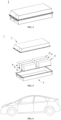
- a fifth aspect of the present application provides an electrical device comprising the secondary battery of the fourth aspect of the present application.
- the positive electrode plate, the secondary battery, and the electrical device of the present application include the positive electrode material composition of the present application, and thus have at least the same advantages as the positive electrode material composition.
- range (s) disclosed in this application is/are defined in the form of lower and upper limits, and a given range is defined by selection of a lower limit and an upper limit that define boundary of the particular range. Ranges defined in this manner may or may not be inclusive of the endpoints, and may be arbitrarily combined. That is, any lower limit may be combined with any upper limit to form a range. For example, if the ranges of 60-120 and 80-110 are listed for a particular parameter, it is to be understood that the ranges of 60-110 and 80-120 are also contemplated.
- transition phases “comprise”, “comprising”, “contain” and “containing” mentioned in the present application mean that it is drafted in an open mode, or it may also mean a close mode.
- the transition phases “comprise”, “comprising”, “contain” and “containing” may mean that other components not listed may also be included or contained, or only the listed components may be included or contained.
- the term "or” is inclusive.
- the phrase “A or B” means “A, B, or both A and B”. More specifically, any of the following conditions meets “A or B”: A is true (or present) and B is false (or absent) ; A is false (or absent) and B is true (or present) ; or both A and B are true (or present) .
- substituents of compounds are disclosed as groups or ranges. It is explicitly expected that such a description includes each individual subcombination of members of these groups and ranges.
- C1-C8 alkyl group is explicitly expected to disclose C1, C2, C3, C4, C5, C6, C7, C8, C1-C8, C1-C7, C1-C6, C1-C5, C1-C4, C1-C3, C1-C2, C2-C8, C2-C7, C2-C6, C2-C5, C2-C4, C1-C3, C1-C2, C2-C8, C2-C7, C2-C6, C2-C5, C2-C4, C2-C4, C2-C4, C2 ⁇ .
- aliphatic hydrocarbon group comprises alkyl, alkenyl, and alkynyl groups.
- heteroaliphatic hydrocarbon group means that the aliphatic hydrocarbon group containing heteroatoms (e.g., N, O, S, etc.) .
- heteroalkyl group means that the alkyl group containing heteroatoms (e.g., N, O, S, etc.), such as alkoxy group, alkylthiogroup, etc.
- the inventors of the present application found in the actual operation that manganese ion leaching out is serious during the deep charging and discharging of the lithium manganese phosphate (LiMnPO 4 ) positive electrode active material.
- the prior art have attempted to coat lithium manganese phosphate with lithium iron phosphate to reduce interfacial side reactions, such coating cannot prevent the migration of the leached manganese ions into the electrolyte.
- the leached manganese ions are reduced to manganese metal after migration to the negative electrode.
- the produced metal manganese is equivalent to "catalyst", which can catalyze the decomposition of the SEI (solid electrolyte interphase) film on the surface of the negative electrode to produce a by-product.
- One part of the by-product is gas, which is prone to cause the battery to expand and affect the safety performance of the battery, and the other part is deposited on the surface of the negative electrode, and blocks the channel of lithium ion in and out of the negative electrode, resulting in increased impedance of the battery and affecting the kinetic performance of the battery.
- the electrolyte and the active lithium ions in the battery are continuously consumed, which also has an irreversible impact on the capacity retention rate of the battery.
- the inventors have found, after extensive research, that by modifying lithium manganese phosphate and by covering the lithium manganese phosphate with multilayers, a new type of positive electrode active material with a core-shell structure can be obtained, and the positive electrode active material can realize a significantly reduced manganese ion dissolution and a reduced lattice change rate, and its use in secondary batteries can improve cycling performance, rate performance, and safety performances of the batteries as well as increase the capacity performance of the batteries.
- the use of the material in secondary batteries can improve cycling performance, rate performance, safety performance and capacity performance of the battery.
- the inventors of the present application have found that the combination of the positive electrode active material and the organopolysiloxane compound can alleviate the erosion of the electrolyte on the surface of the positive electrode active material, and thus help to give full play to the electrochemical performance of the positive electrode active material.
- a first aspect of the present application provides a positive electrode material composition
- a positive electrode active material comprising a positive electrode active material with a core-shell structure and an organopolysiloxane compound
- the positive electrode active material comprises a core and a shell covering the core
- the core has a chemical formula of Li 1+x Mn 1-y A y P 1-z R z O 4 , x being any value in the range of -0.100 to 0.100, optionally any value in the range of -0.005 to 0.002, y being any value in the range of 0.001 to 0.500, and z being any value in the range of 0.001 to 0.100;
- A being one or more elements selected from Zn, Al, Na, K, Mg, Mo, W, Ti, V, Zr, Fe, Ni, Co, Ga, Sn, Sb, Nb, and Ge, optionally one or more elements selected from Fe, Ti, V, Ni, Co, and Mg;
- R being one or more elements selected from B, Si,
- the above range for the x value is not only for the stoichiometric number of each element as A, but also for the sum of the stoichiometric numbers of each element as A.
- each of the respective stoichiometric numbers y1, y2»and yn of respective A1, A2 «and An must fall within the numerical range defined by the present application for x, and the sum of y1, y2ising and xn must also fall within such numerical range of the present application.
- R is more than two elements
- the limitations on numerical ranges for the stoichiometric numbers of R in the present application also have the above meaning.
- A is an element selected from one, two, three, or four of Zn, Al, Na, K, Mg, Mo, W, Ti, V, Zr, Fe, Ni, Co, Ga, Sn, Sb, Nb, and Ge
- one of n1, n2, n3, and n4 is zero, and the rest are not zero; and more optionally, two of n1, n2, n3 and n4 are zero and the rest are not zero; more optionally, three of n1, n2, n3 and n4 are zero and the rest are not zero.
- the magnitude of x is affected by the magnitude of the valence states of A and R, and the magnitude of y and z, to ensure that the whole system exhibits electroneutrality. If the value of x is too small, it will lead to a lower lithium content of the whole core system, affecting the capacity exertion of the positive electrode active material.
- the value of y will limit the total amount of all the dopant elements, and if y is too small, i.e., the amount of doping is too small, the dopant elements cannot play a role, and if y is more than 0.5, it will lead to a lower content of Mn in the system, affecting the voltage plateau of the material.
- the R element is doped at the position of P. Since the P-O tetrahedron is more stable, and if the value of z is too large, the stability of the material will be affected, thus the value of z is limited to 0.001 to 0.100.
- the positive electrode active material of the present application can improve the capacity exertion, cycling performance and safety performance of secondary batteries.
- the lithium manganese phosphate positive electrode active material of the present application has a core-shell structure, and by doping the manganese and phosphorus sites of the lithium manganese phosphate core with element A and element R, respectively, not only can it effectively reduce the leaching out of manganese ions, and thus reduce manganese ions migrating to the negative electrode, and reduce the electrolyte consumed by the decomposition of the SEI membrane, and improve the cycling performance and the safety performance of the secondary batteries, but also can promote the adjustment of Mn-O bond, lowering the migration barrier of lithium ion, promoting lithium ion's migration, and improving the rate performance of the secondary battery; by covering the core with a first cladding layer comprising crystalline pyrophosphate, the migration resistance of manganese ions can be further increased, reducing their leaching, and reducing the content of surface lithium im
- the element A doped in the manganese position of the lithium manganese phosphate also helps to reduce the rate of lattice change of the e lithium manganese phosphate in the process of de-intercalation and intercalation of lithium in this material, improve the structural stability of the lithium manganese phosphate positive electrode active material, greatly reduce the leaching of the manganese ions and reduce the oxygen activity on the surface of the particles; and the element R doped in the phosphorus position also helps to change the degree of difficulty of the change in the bond length of the Mn-O bond, thereby improving the electronic conductivity and reducing the lithium ion migration barrier, promoting lithium ion migration, and improving the rate performance of the secondary battery.
- the entire core system remains electrically neutral, which ensures that there are as few defects and heterogeneous phases in the positive electrode active material as possible. If there is an excessive amount of transition metal (e.g., manganese) in the positive electrode active material, due to the more stable structure of the material system itself, the excess transition metal is likely to precipitate in the form of monomers or form a heterogeneous phase inside the crystal lattice, and keeping the electroneutrality can keep such heterogeneous phases as small as possible. Additionally, ensuring the system is electrically neutral can also lead to the creation of lithium vacancies in the positive electrode active material in some cases, which can lead to better kinetic performance of the positive electrode active material.
- transition metal e.g., manganese
- the positive electrode material composition of the present application comprises a positive electrode active material and an organopolysiloxane compound.
- the inventors of the present application found that the combination of the positive electrode active material with the organopolysilane compound can alleviate the erosion of the surface of the positive electrode active material caused by the electrolyte, and reduce the leaching out of Mn, so as to improve the electrochemical performance of the positive electrode active material.
- the possible reason is that the Si-O skeleton of the organopolysiloxane compound can remove F ions from the electrolyte, thereby reducing the acidity of the electrolyte and alleviating the erosion of the surface of the positive electrode active material caused by acidic substances in the electrolyte.
- the organopolysiloxane compound also has a certain hydrophobicity, and can be used to prepare a positive electrode plate with positive electrode active material. A contact angle between the prepared positive electrode plate and the electrolyte is increased, so as to alleviate the erosion of the surface of the positive electrode active material caused by the electrolyte.
- the electrical device such as the positive electrode plate and secondary battery using the positive electrode material composition of the present application can have high energy density, while further improving cycling performance, safety performance and/or rate performance.
- the average particle size of the core prepared in the present application ranges from 50 nm to 500 nm, and the Dv50 is from 200 nm to 300 nm.
- the primary particle size of the core is within the range of 50 nm to 500 nm, and the Dv50 is from 200 nm to 300 nm. If the average particle size of the core is too large (more than 500 nm), the capacity exertion of the secondary batteries using the material will be affected; if the average particle size of the core is too small, it has a large specific surface area and is prone to agglomeration, making it difficult to achieve uniform coating.
- the inventors cut the middle region (the inner core region) of the prepared positive electrode active material particles by a focused ion beam (referred to as FIB), and tested it by a transmission electron microscope (referred to as TEM) as well as an X-ray energy spectrum analysis (referred to as EDS), and found that the distribution of the various elements was uniform, and that aggregation did not occur.
- FIB focused ion beam
- TEM transmission electron microscope
- EDS X-ray energy spectrum analysis
- crystalline means having a degree of crystallinity of 50% or more, i.e., 50% to 100%. A crystallinity of less than 50% is referred to as the glassy (or amorphous) state.
- the crystalline pyrophosphates and crystalline phosphates described in the present application have a crystallinity of 50% to 100%.
- Pyrophosphates and phosphates with a certain degree of crystallinity are not only conducive to giving full play to the functions of the pyrophosphate cladding layer in hindering the leaching out of manganese ions and the excellent lithium ion conductivity of the phosphate cladding layer, and reducing the interfacial side reactions, but also enable better lattice matching of the pyrophosphate cladding layer and the phosphate cladding layer so that a closer bonding of the cladding layers is achieved.
- the crystallinity of crystalline pyrophosphate as the material for the first cladding layer and crystalline phosphate as the material for the second cladding layer of the positive electrode active material can be tested by conventional technical means in the field, for example, by density method, infrared spectroscopy, differential scanning calorimetry, and nuclear magnetic resonance absorption method, and can also be tested, for example, by X-ray diffraction method.
- a specific method for testing the crystallinity of crystalline pyrophosphate as the material for the first cladding layer and crystalline phosphate as the material for the second cladding layer of the positive electrode active material by the X-ray diffraction method may comprise the steps of taking a certain amount of the positive electrode active material powder and measuring the total scattering intensity by X-rays, which is the sum of the scattering intensities of the entire space substance, and is only related to the intensity of the primary rays, the chemical structure of the positive electrode active material powder, the total electron number (i.e., the mass), and not with the ordinal state of the sample; the crystalline scattering is then separated from the amorphous scattering from the diffractogram, and the degree of crystallinity, i.e., the ratio of the scattering of the crystalline portion of the scattering to the total intensity of the scattering.
- the crystallinity of the pyrophosphate and phosphate in the cladding layer can be adjusted, for example, by adjusting the process conditions of the sintering process such as the sintering temperature, the sintering time and the like.
- the pyrophosphate as the first cladding layer can effectively isolate the dopant metal ions from the electrolyte.
- the crystalline pyrophosphate has a stable structure, so the coating with crystalline pyrophosphate can effectively inhibit the leaching out of the transition metal and improve the cycling performance.
- the bonding between the first cladding layer and the core is similar to a heterojunction, and the firmness of the bonding is limited by the degree of lattice matching.
- the tight bonding can ensure that the cladding layer will not fall off in the subsequent cycling process, which is conducive to ensuring the long-term stability of the positive electrode active material.
- the measurement of the degree of bonding between the first cladding layer and the core is mainly carried out by calculating the degree of mismatch between the core and the respective lattice constant of the coating.
- the matching degree between the core and the first cladding layer is improved and the core and the pyrophosphate cladding layer can be more tightly bonded with each other as compared to the non-doped elements.
- Crystalline phosphate is chosen as the second cladding layer, firstly, because it has a higher lattice matching with the first cladding layer of crystalline pyrophosphate (the mismatch is only 3%) ; secondly, the stability of the phosphate itself is better than that of the pyrophosphate, and covering the pyrophosphate with it is conducive to the improvement of the stability of the positive electrode active material.
- the structure of crystalline phosphate is very stable, and it has excellent ability to conduct lithium ions, so the use of crystalline phosphate for covering can effectively reduce the interfacial side reaction between positive electrode active material and electrolyte, thus improving the high-temperature cycling performance and high-temperature storage performance of secondary battery.
- the lattice matching between the second cladding layer and the first cladding layer is similar to the bonding between the first cladding layer and the nucleus as described above, and when the lattice mismatch is less than 5%, the lattice matching is better, and the two materials are easy to be bonded tightly.
- the main reason for carbon as the third cladding layer is the better electronic conductivity of the carbon layer. Since electrochemical reactions occur when applied in secondary batteries, which require the participation of electrons. Carbon with excellent electrical conductivity can be used to cover the positive electrode active material in order to increase the electron transfer between particles and at different locations on the particles. Coating with carbon can effectively improve the electrical conductivity and desolventization of the positive electrode active material.
- the primary particles of the positive electrode active material have an average particle size in the range of 50 nm to 500 nm, with a median volume particle size Dv50 in the range of 200 nm to 300 nm. Since the particles will agglomerate, the actual measured size of the secondary particles after agglomeration may be from 500 nm to 40, 000 nm. The size of the particles of the positive electrode active material affects the processing of the material and the compaction density performance of the electrode plate.
- the average particle size of the primary particles By selecting the average particle size of the primary particles to be within the above range, it is thereby possible to effectively avoid the following: the average particle size of the primary particles of the positive electrode active material being too small, which may cause agglomeration of the particles and make the particles difficult to be dispersed, and which requires a higher amount of binder, resulting in a poorer brittleness of the electrode plate; and the average particle size of the primary particles of the positive electrode active material being too large, which may result in larger inter-particle gaps and a lower compaction density.
- the lattice change rate of lithium manganese phosphate and manganese ion's leaching in the process of de-intercalation and intercalation of lithium can be effectively suppressed, thereby enhancing the high-temperature cycling performance and high-temperature storage performance of the secondary battery.
- the crystalline pyrophosphate in the first cladding layer has an interplanar spacing ranging from 0.293 nm to 0.470 nm, and the angle of the crystal direction (111) ranges from 18.00° to 32.00°; the crystalline phosphate in the second cladding layer has an interplanar spacing ranging from 0.244 nm to 0.425 nm, and the angle of the crystal direction (111) ranges from 20.00° to 37.00°.
- Both the first cladding layer and the second cladding layer in the positive electrode active material described in the present application use crystalline substances.
- the crystalline pyrophosphates and crystalline phosphates in the cladding layer can be characterized by means of techniques that are conventional in the art or, for example, with the aid of transmission electron microscopy (TEM) . Under TEM, the core and the cladding layer can be distinguished by testing the interplanar spacing.
- TEM transmission electron microscopy
- the specific test method for the interplanar spacing and angle of crystalline pyrophosphate and crystalline phosphate in the cladding layers may include the following steps: taking a certain amount of the sample powder of the coated positive electrode active material in a test tube and injecting a solvent, such as alcohol, into the test tube, and then carrying out sufficient stirring and dispersion, and then taking an appropriate amount of the above solution with a clean disposable plastic pipette and adding it dropwise to a 300-mesh copper mesh, and then leaving part of the powder on the copper mesh, and transferring the copper mesh with the sample to the TEM sample chamber for testing to obtain the original picture of the TEM test.
- a solvent such as alcohol
- the original picture obtained from the above TEM test was opened in the diffractometer software and Fourier transformed to obtain the diffraction pattern, and the distance from the diffracted spot to the center position in the diffraction pattern was measured to obtain the interplanar spacing, and the angle could be calculated according to Bragg's equation.
- the difference between the range of the interplanar spacing of the crystalline pyrophosphate and that of the crystalline phosphate can be directly judged by the value of the interplanar spacing.
- Crystalline pyrophosphates and crystalline phosphates having interplanar spacing and angle within the above range can more effectively inhibit the lattice change rate of lithium manganese phosphate and the leaching out of manganese ions in the process of de-intercalation and intercalation of lithium, thereby enhancing the high-temperature cycling performance and high-temperature storage performance of the secondary battery.
- x is any value in the range of -0.100 to 0.100, for example, x may be 0.001, 0, - 0.001, -0.002, -0.003, -0.004, and 005.
- x is any value in the range of -0.005 to 0.002.
- y is any value in the range of 0.001 to 0.500, for example, y maybe0.001, 0.100, 0.200, 0.300, 0.350, 0.400, 0.450, and 0.500.
- z is any value in the range of 0.001 to 0.100, for example, z maybe0.001, 0.002, 0.003, 0.004, 0.005, and 0.100.
- the ratio of y to (1-y) is from 1:10 to 1:1, optionally from 1:4 to 1:1.
- y denotes the sum of the stoichiometric numbers of the Mn-site doping element A.
- the ratio of z to (1-z) is from 1:9 to 1:999, optionally from 1:499 to 1:249.
- z denotes the sum of the stoichiometric numbers of the P-position doping element R.
- the carbon of the third cladding layer is a mixture of SP2 carbon and SP3 carbon; optionally, the molar ratio of the SP2 carbon to the SP3 carbon is any value in the range of 0.1 to 10, optionally any value in the range of 2.0 to 3.0.
- the molar ratio of the SP2 carbon to the SP3 carbon may be about 0.1, about 0.2, about 03, about 0.4, about 0.5, about 0.6, about 0.7, about 0.8, about 0.9, about 1, about 2, about 3, about 4, about 5, about 6, about 7, about 8, about 9, or about 10, or any value within any of the foregoing ranges.
- the overall electrochemical performance of the secondary battery is thereby enhanced.
- the following can be effectively avoided: if the carbon in the cladding layer is all in the amorphous SP3 morphology, the electrical conductivity is poor, and if it is all in the graphitized SP2 morphology, although the electrical conductivity is good, there are few lithium-ion pathways, which is not conducive to the de-intercalation of lithium-ion.
- limiting the molar ratio of the SP2 carbon to the SP3 carbon to the above range achieves good electrical conductivity and ensures the lithium ion pathway, and is therefore conducive to improving the kinetic performance and cycling performance of the secondary battery.
- the mixing ratio of the SP2 form and the SP3 form of the carbon for the third cladding layer can be controlled by sintering conditions such as sintering temperature and sintering time.
- sintering conditions such as sintering temperature and sintering time.
- sucrose is used as a carbon source to prepare the third cladding layer
- the sucrose is cracked at a high temperature and then deposited on the second cladding layer while at the same time under the action of high temperature, a carbon cladding layer with both the SP3 form and the SP2 form is produced.
- the ratio of the SP2 carbon to the SP3 carbon may be regulated by selecting the high temperature cracking conditions and the sintering conditions.
- the structure and characterization of the carbon for the third cladding layer can be determined by Raman (Raman) spectroscopy as follows: the molar ratio of the SP2 carbon to the SP3 carbon is confirmed by splitting the energy spectrum of the Raman test to obtain I d /I g (I d is the intensity of the peak of the carbon in the SP3 form and I g is the intensity of the peak of the carbon in the SP2 form) .
- the first cladding layer has a coating amount of greater than 0 and less than or equal to 6 wt%, optionally greater than 0 and less than or equal to 5.5 wt%, more optionally greater than 0 and less than or equal to 2 wt%, based on the weight of the core.
- the second cladding layer has a coating amount of greater than 0 and less than or equal to 6 wt%, optionally greater than 0 and less than or equal to 5.5 wt%, and more optionally between 2 wt% and 4 wt%, based on the weight of the core.
- the third cladding layer has a coating amount of greater than 0 and less than or equal to 6 wt%, optionally greater than 0 and less than or equal to 5.5 wt%, more optionally greater than 0 and less than or equal to 2 wt%, based on the weight of the core.
- each layer has a non-zero amount of covering.
- the coating amount of the three cladding layers is preferably within the above range, whereby the core can be sufficiently coated and at the same time further improve the cycling performance, safety performance, and/or rate performance of the secondary battery without sacrificing the gram capacity of the positive electrode active material.
- the coating amount for the first cladding layer, by controlling the coating amount within the above range, the following situations can be effectively avoided: if the coating amount is too small, the thickness of the cladding layer is relatively thin, which may not be able to effectively impede the migration of the transition metal; if the coating amount that is too large, the cladding layer is too thick, which may affect the migration of Li + , and thus affect the rate performance of the positive electrode active material.
- the coating amount for the second cladding layer, by controlling the coating amount within the above range, the following situations can be effectively avoided: if the coating amount is too much, the overall platform voltage of the positive electrode active material may be affected; if the coating amount is too little, it may not be able to realize a sufficient coating effect.
- the carbon covering mainly serves to enhance the electron transfer between the particles, however, since the structure also contains a large amount of amorphous carbon, the density of the carbon is relatively low, and therefore, if the coating amount is too large, the compaction density of the electrode plate may be affected.
- the first cladding layer has a thickness of 1 nm to 10 nm.
- the second cladding layer has a thickness of 2 nm to 15 nm.
- the third cladding layer has a thickness of 2 nm to 25 nm.
- the thickness of the first cladding layer may be about 2 nm, about 3 nm, about 4 nm, about 5 nm, about 6 nm, about 7 nm, about 8 nm, about 9 nm, or about 10 nm, or in any range of any of the above values.
- the thickness of the second cladding layer may be about 2 nm, about 3 nm, about 4 nm, about 5 nm, about 6 nm, about 7 nm, about 8 nm, about 9 nm, about 10 nm, about 11 nm, about 12 nm, about 13 nm, about 14 nm, about 15 nm, or in any range of any of the above values.
- the thickness of the third cladding layer may be about 2 nm, about 3 nm, about 4 nm, about 5 nm, about 6 nm, about 7 nm, about 8 nm, about 9 nm, about 10 nm, about 11 nm, about 12 nm, about 13 nm, about 14 nm, about 15 nm, about 16 nm, about 17 nm, about 18 nm, about 19 nm, about 20 nm, about 21 nm, about 22 nm, about 23 nm, about 24 nm, or about 25 nm, or in any range of any of the above values.
- the thickness of the first cladding layer is within the range of 1 nm to 10 nm, it is possible to avoid an unfavorable effect on the kinetic performance of the positive electrode active material that may arise when it is too thick, and it is possible to avoid a problem that may not be able to efficiently hinder the migration of the transition metal ions when it is too thin.
- the thickness of the second cladding layer is within the range of 2 nm to 15 nm, the surface structure of the second cladding layer is stable, and the side reaction with the electrolyte is small, and thus the interfacial side reaction can be effectively mitigated, thereby improving the high-temperature cycling performance and high-temperature storage performance of the secondary battery.
- the electrical conductivity of the positive electrode active material can be improved and the compaction density of the positive electrode plate prepared using the positive electrode active material can be improved.
- the test for the thickness of the cladding layer is mainly carried out by FIB, and the specific method may comprise the following steps: randomly selecting a single particle from the positive electrode active material powder to be tested, cutting a thin slice with a thickness of about 100 nm from the middle position of the selected particle or from the vicinity of the middle position, and then carrying out a TEM test on the thin slice, measuring the thickness of the cladding layer, measuring 3-5 positions, and taking the average value.
- the content of manganese is in the range of 10 wt% to 35 wt%, optionally in the range of 15 wt% to 30 wt%, and more optionally in the range of 17 wt% to 20 wt%, based on the weight of the positive electrode active material.
- the content of phosphorus is in the range of 12 wt% to 25 wt%, optionally in the range of 15 wt% to 20 wt%, based on the weight of the positive electrode active material.
- the weight ratio of manganese to phosphorus is in the range of 0.90 to 1.25, optionally in the range of 0.95 to 1.20.
- the amount of manganese may correspond to the amount of the core.
- limiting the content of manganese to the above range can effectively avoid problems such as deterioration of the structural stability of the positive electrode active material and decrease in density that may be caused if the content of manganese is too large, so as to improve the performance of the secondary battery in terms of cycling, storage and compaction density; and it can avoid problems such as a low voltage plateau that may be caused if the content of manganese is too small, so as to improve the energy density of the secondary battery.
- limiting the content of phosphorus to the above range can effectively avoid the following situations: if the content of phosphorus is too large, it may lead to the covalence of P-O being too strong and affect the conductivity of the small polarizers, thus affecting the electrical conductivity of the positive electrode active material; if the content of phosphorus is too small, it may cause the lattice structure of the pyrophosphate in the core, in the first cladding layer and/or of the phosphate in the second cladding layer to be less stable, thereby affecting the overall stability of the positive electrode active material.
- the weight ratio of the manganese content to the phosphorus content has the following effects on the performance of the secondary battery: if the weight ratio is too large, it means that there is too much manganese, the manganese ions' leaching increases, which affects the stability and capacity exertion of the positive electrode active material, and thus affects the cycling performance and the storage performance of the secondary battery; if the weight ratio is too small, it means that there is too much phosphorus, which is prone to form a heterogeneous phase, causing the discharge voltage plateau of the positive electrode active material to decrease, thus the energy density of the secondary battery is reduced.
- the measurement of the elemental manganese and the elemental phosphorus may be carried out by technical means conventional in the art.
- the content of the manganese element and the phosphorus element is measured using the following method: the material is dissolved in dilute hydrochloric acid (concentration 10-30%), the content of each element of the solution is tested using ICP, and then the content of the manganese element is measured and converted to obtain its weight percentage.
- the positive electrode active material with a core-shell structure has a lattice change rate of less than 4%, optionally less than 3.8%, and more optionally from 2.0% to 3.8% before and after complete deintercalation and intercalation of lithium.
- the de-intercalation and intercalation of lithium in manganese phosphate (LiMnPO 4 ) is a two-phase reaction.
- the interfacial stress of the two phases is determined by the magnitude of the lattice change rate before and after the deintercalation and intercalation of lithium, and the smaller the lattice change rate is, the smaller the interfacial stress is, and the easier the Li + transport is. Therefore, reducing the lattice change rate of the core will be favorable to enhance the Li + transport ability, thereby improving the multiplicity performance of the secondary battery.
- the positive electrode active material having a core-shell structure described in the present application is capable of realizing a lattice change rate before and after the deintercalation and intercalation of lithium of less than 4%, and thus the use of the positive electrode active material is capable of improving the multiplication rate performance of the secondary battery.
- the lattice change rate can be measured by methods known in the art, such as X-ray diffraction (XRD) mapping.
- the positive electrode active material with a core-shell structure has a Li/Mn anti-site defect concentration of 4% or less, optionally 2.2% or less, more optionally 1.5% to 2.2%.
- the term Li/Mn anti-site defect refers to interchange of Li + with Mn 2+ in terms of its site in the LiMnPO 4 lattice. Accordingly, the Li/Mn anti-site defect concentration refers to a percentage of Li + interchanged with Mn 2+ in the positive electrode active material relative to the total amount of Li + .
- the Li/Mn anti-site defect concentration in the present application may, for example, be tested according to JIS K 0131-1996.
- the positive electrode active material with a core-shell structure described in the present application is capable of realizing the lower Li/Mn anti-site defect concentration described above.
- the mechanism is not yet well understood, the inventors of the present application speculate that since Li + and Mn 2+ will swap positions in the LiMnPO 4 lattice, and the Li + transport channel is a one-dimensional channel, Mn 2+ will be difficult to migrate in the Li + channel, which in turn hinders the Li + transport.
- the positive electrode active material with a core-shell structure described in the present application is able to avoid Mn 2+ from hindering Li + transmission and at the same time enhance the capacity exertion and rate performance of the positive electrode active material due to the low concentration of Li/Mn anti-site defects, which is within the above range.
- the positive electrode active material has a compaction density of 2.2 g/cm 3 or more, optionally 2.2 g/cm 3 or more and 2.8 g/cm 3 or less, at 3T (tonne) .
- increase of the compaction density is conducive to improving volumetric energy density of batteries.
- Compaction density can be measured according to GB/T 24533-2009.
- the positive electrode active material with a core-shell structure has a surface oxygen valence of -1.90 or less, optionally -1.90 to -1.98.
- the stable valence of oxygen is originally -2, and the closer the valence state is to the -2, the stronger the ability to gain electrons, i.e., the stronger the oxidizability, and usually, the surface valence is below -1.7.
- the surface oxygen valence state can be measured by methods known in the art, such as by electron energy loss spectroscopy (EELS) .
- the organopolysiloxane compound comprises at least one structural unit shown in Formula 1,
- R 1 and R 2 each independently represent H or at least one of the group consisting of the following functional groups: -COOH, -OH, -SH, -CN, -SCN, amino groups, phosphate groups, carboxylate groups, amide groups, aldehyde groups, sulfonyl groups, polyether chain segments, C 1 -C 20 aliphatic hydrocarbon groups, C 1 -C 20 halogenated aliphatic hydrocarbon group, C 1 -C 20 heteroaliphatic hydrocarbon groups, C 1 -C 20 halogenated heteroaliphatic hydrocarbon groups, C 6 -C 20 aromatic hydrocarbon groups, C 6 -C 20 halogenated aromatic hydrocarbon groups, C 2 -C 20 heteroaromatic hydrocarbon groups, and C 2 -C 20 halogenated heteroaromatic hydrocarbon groups.
- R 1 and R 2 each independently represent H or at least one of the group consisting of the following functional groups: -COOH, -OH, -SH, amino groups, phosphate groups, polyether chain segments, Ci-Cs alkyl groups, Ci-Cs haloalkyl groups, Ci-Cs heteroalkyl groups, Ci-Cs haloheteroalkyl groups, C 2 -C 8 alkenyl groups, C 2 -C 8 haloalkenyl groups, and phenyl.
- R 1 and R 2 each independently represent H or at least one of the group consisting of the following functional groups: -OH, -SH, amino groups, phosphate groups, polyether chain segments, C 1 -C 8 alkyl groups, Ci-Cs haloalkyl groups, C 1 -C 8 heteroalkyl groups, Ci-Cs haloheteroalkyl groups, C 2 -C 8 alkenyl groups, and C 2 -C 8 haloalkenyl groups.
- These functional groups can complex manganese ions and/or react with acidic substances in the electrolyte, thereby the leaching out of Mn and Mn-site doping elements, and further improving the cycling performance and storage performance of the secondary battery.
- the Si in the Si-O skeleton of the organopolysiloxane compound is more electron-deficient, thereby further enhancing the affinity with F-containing ions in the electrolyte, alleviating the erosion of the surface of the positive electrode active material caused by acidic substances in the electrolyte and reducing the leaching out of Mn and Mn-site doping elements, so as to significantly improve the cycling performance and storage performance of the secondary battery.
- the organopolysiloxane compound comprises one or more selected from of a linear polysiloxane, and a cyclic polysiloxane, optionally, the organopolysiloxane compound is selected from a linear polysiloxane.
- the erosion of the surface of the positive electrode active material caused by acidic substances in the electrolyte can be further alleviated, and the leaching out of Mn and Mn-site doping elements can be reduced, so as to significantly improve the cycling performance and storage performance of the secondary battery.
- the Si-O skeleton of the cyclic polysiloxane Due to the delocalization of electrons in the ring of the cyclic polysiloxane, the Si-O skeleton of the cyclic polysiloxane has a lower affinity for electron-rich F-containing ions than that of the linear polysiloxane, and thus the removal efficiency of F-containing ions in the electrolyte is slightly lower, the effect of reducing the leaching out of Mn and Mn-site doping elements is slightly weak, and the effect of improving the cycling performance of the battery is slightly poor.
- the linear polysiloxane further comprises a capping group.
- the capping group comprises at least one of the group consisting of the following functional groups: polyethers, Ci-Cs alkyl groups, Ci-Cs haloalkyl groups, Ci-Cs heteroalkyl groups, Ci-Cs haloheteroalkyl groups, C 2 -C 8 alkenyl groups, C 2 -C 8 haloalkenyl groups, C 6 -C 20 aromatic hydrocarbon groups, Ci-Cs alkoxy groups, C 2 -C 8 epoxy groups, hydroxyl groups, Ci-Cs hydroxyalkyl groups, amino groups, C 1 -C 8 aminoalkyl groups, carboxyl groups, and C 1 -C 8 carboxyl alkyl groups.
- the cyclic polysiloxane has a molecular formula shown in Formula 2, wherein m represents the degree of polymerization of the structural unit shown in Formula 1.
- m represents the degree of polymerization of the structural unit shown in Formula 1.
- the linear polysiloxane includes, but is not limited to, one or more of polydimethyl siloxane, polydiethyl siloxane, polymethyl ethyl siloxane, polymethyl vinyl siloxane, polyphenyl methyl siloxane, polymethyl hydrosiloxane, carboxyfunctionalized polysiloxane, polymethyl chloropropyl siloxane, polymethyl trifluoropropyl siloxane, perfluorooctyl methyl polysiloxane, mercaptopropyl polysiloxane, aminoethyl aminopropyl polydimethylsiloxane, methoxy terminated polydimethylsiloxane, hydroxypropyl terminated polydimethylsiloxane, aminopropyl terminated polydimethylsiloxane, terminal epoxy polysiloxane, terminal hydroxyl polydimethylsiloxane, terminal polyether polydimethylsiloxane,
- the linear polysiloxane comprises one or more of polydimethyl siloxane, polymethyl chloropropyl siloxane, polymethyl trifluoropropyl siloxane, mercaptopropyl polysiloxane, aminoethyl aminopropyl polydimethylsiloxane, terminal hydroxyl polydimethylsiloxane, terminal polyether polydimethylsiloxane, pendant phosphate-grafted polydimethylsiloxane.
- the linear polysiloxane includes, but is not limited to, one or more of cyclic polydimethylsiloxane, cyclic polymethyl vinyl siloxane, cyclic polymethyl hydrosiloxane, and cyclic polymethyl trifluoropropyl siloxane.
- the cyclic polysiloxane comprises one or more of 1, 3, 5, 7-octamethyl cyclotetrasiloxane, 1, 3, 5, 7-tetrahydro-1, 3, 5, 7-tetramethyl cyclotetrasiloxane, decamethylcyclopentasiloxane, 2, 4, 6, 8-tetramethyl cyclotetrasiloxane, 2, 4, 6, 8-tetramethyl-2, 4, 6, 8-tetravinyl cyclotetrasiloxane, hexadecamethylcyclooctasiloxane, and tetradecamethylcycloheptasiloxane.
- the organopolysiloxane compound has a number average molecular weight of 300, 000 or less, such as of 400 to 300000, 400 to 200000, 400 to 100000, 400 to 80000, 400 to 50000, 400 to 20000, 400 to 10000, 1000 to 100000, 1000 to 50000, 1000 to 20000 or 1000 to 10000.
- the number average molecular weight of the organopolysiloxane compound may be determined by methods known in the art, such as by gel permeation chromatography (GPC) .
- GPC gel permeation chromatography
- a PL-GPC 220 high temperature gel permeation chromatograph may be used for testing.
- the organopolysiloxane compound may be either an oligomer or a polymer.
- the number average molecular weight of the organopolysiloxane compound is within the suitable ranges, it is possible to combine good kinetic properties and high-temperature stability of the battery.
- the following conditions may be effectively avoided: if the number average molecular weight of the organopolysiloxane compound is too small, it may result in poor hydrophobicity, which may not effectively increase the contact angle between the positive film layer and the electrolyte, and then may not effectively alleviate the erosion of on the surface of the positive electrode active material caused by the electrolyte, resulting in a significant improvement of the cycling performance and/or high-temperature stability of the battery; and if the number average molecular weight of the organopolysiloxane compound is too high, it may result in strong hydrophobicity, which may be not conducive to the dispersion of the slurry, thus affecting the improvement effect on the performance of the battery.
- a polar functional group is present in a mass percentage ⁇ in the organopolysiloxane compound, 0 ⁇ ⁇ ⁇ 50%, optionally, 5% ⁇ ⁇ ⁇ 30%.
- the mass percentage of the polar functional groups in the organopolysiloxane compound means the mass percentage of the polar functional groups in R 1 , R 2 and the capping groups in the organopolysiloxane compound.
- ⁇ represents a mass fraction of these polar functional groups in the organopolysiloxane compound.
- ⁇ represents the sum of the mass fractions of the polar functional groups and divalent to tetravalent methyl groups (e.g., -CH 2 , -CH-, -C-, etc.) directly connected with the polar functional groups in the organopolysiloxane compound.
- the divalent to tetravalent methyl groups represent carbon atoms that are directly connected with the polar functional groups and are located between the polar functional groups and the silicon atoms, and other non-polar functional groups connected with the carbon atoms.
- ⁇ refers to the mass percentage of -CF 3 , excluding the ethylidene groups.
- ⁇ refers to the mass percentage of -CH 2 Cl, excluding the ethylidene groups.
- ⁇ refers to the mass percentage of -CH 2 OH.
- the mass percentage of the polar functional group in the organopolysiloxane compound may be determined by methods known in the art, such as by titration (e.g. acid-base titration, redox titration, and precipitation titration), infrared spectroscopy, and nuclear magnetic resonance spectroscopy.
- titration e.g. acid-base titration, redox titration, and precipitation titration
- infrared spectroscopy e.g. acid-base titration, redox titration, and precipitation titration
- infrared spectroscopy e.g., infrared spectroscopy
- nuclear magnetic resonance spectroscopy e.g., nuclear magnetic resonance spectroscopy.
- the mass percentage of the polar functional group in the organopolysiloxane compound is within the suitable ranges, it has a better effect on reducing the acidity of the electrolyte and removing F ions in the electrolyte, thereby better alleviating the erosion of the surface of the positive electrode active material caused by acidic substances in the electrolyte, and better improving the cycling performance and/or high-temperature stability of the battery.
- the following conditions may be effectively avoided: if the content of the polar functional groups in the organopolysiloxane compound is too high, the effect on reducing the acidity of the electrolyte and removing F ions in the electrolyte may not be further improved, but a smaller contact angle between the positive electrode film layer and the electrolyte may be obtained, thereby resulting in a significant improvement of the cycling performance of the secondary battery.
- the organopolysiloxane compound is present in an amount of 0.01 wt% to 2 wt%, optionally 0.1 wt% to 2 wt%, based on the total weight of the positive electrode material composition.
- the amount of the organopolysiloxane compound is within the suitable ranges, it has a better effect on reducing the acidity of the electrolyte and removing F ions in the electrolyte, thereby better alleviating the erosion of the surface of the positive electrode active material caused by acidic substances in the electrolyte, and better improving the cycling performance and storage performance of the secondary battery.
- the following conditions may be effectively avoided: if the amount of the organopolysiloxane compound is too high, the electrolyte infiltration of the positive electrode film layer and the kinetic performance of the secondary battery may be affected, and at the same time, the energy density of the battery may be reduced since the organopolysiloxane compound does not provide a capacity; if the amount of the organopolysiloxane compound is too low, the effect on reducing the acidity of the electrolyte and removing F ions in the electrolyte is not significant, and the erosion of the surface of the positive electrode active material caused by acidic substances in the electrolyte cannot be effectively alleviated, thereby resulting in a significant improvement of the cycling performance and/or high-temperature storage performance of the secondary battery.
- the positive electrode material composition further comprises a binder.
- the binder may be a substance known in the art to have a bonding effect.
- the binder comprises at least one of polyvinylidene fluoride (PVDF), polytetrafluoroethylene (PTFE), vinylidene fluoride-tetrafluoroethylene-propylene terpolymer, vinylidene fluoride-hexafluoropropylene-tetrafluoroethylene terpolymer, tetrafluoroethylene-hexafluoropropylene copolymer, and fluorinated acrylate resin.
- PVDF polyvinylidene fluoride
- PTFE polytetrafluoroethylene
- PTFE polytetrafluoroethylene
- vinylidene fluoride-hexafluoropropylene-tetrafluoroethylene terpolymer vinylidene fluoride-hexafluoropropylene-tetrafluoro
- the binder is present in a content of 1.79 wt% to 10 wt%, and optionally 2 wt% to 5 wt%, based on the total weight of the positive electrode material composition.
- the positive electrode material composition further comprises a conductive agent.
- the conductive agent may be a substance known in the art to have an electron conduction effect.
- the positive conductive agent comprises at least one of superconducting carbon, conductive graphite, acetylene black, carbon black, Ketjen black, carbon dots, carbon nanotubes, graphene, and carbon nanofibers.
- the conductive agent is present in a content of 0.2 wt% to 10 wt%, and optionally 0.5 wt% to 5 wt%, based on the total weight of the positive electrode material composition.
- the positive electrode material composition has a powder resistivity of 4 ⁇ /cm to 50 ⁇ /cm, optionally from 4 ⁇ /cm to 40 ⁇ /cm at 12MPa.
- the powder resistivity of the positive electrode material composition in a suitable range enables the battery to have a better kinetic performance.
- the powder resistivity of the positive electrode material composition may be determined by a method known in the art. For example, according to GB/T 30835-2014, the powder resistivity tester can be used for testing.
- An exemplary test method includes steps of weighing a certain amount of powder of a sample to be tested in a special mold, setting different pressure, and obtaining the powder resistivity at different pressures. In the present application, the pressure can be set to 12 Mpa.
- the testing instrument can be Suzhou lattice ST2722-SZ type four probe powder resistivity tester.
- the positive electrode material composition has a specific surface area of 8 m 2 /g to 20 m 2 /g, optionally 8 m 2 /g to 15 m 2 /g.
- the specific surface area of the positive electrode material composition in a suitable range can reduce interfacial side reactions between the positive electrode plate using the composition and the electrolyte, and reduce the volume expansion of the battery, thereby enabling the battery to have a better electrochemical performance.
- the specific surface area of the positive electrode material composition can be determined by a method known in the art. For example, according to GB/T 19587-2017, the nitrogen adsorption specific surface area analysis test method can be used for testing, and the BET (BrunauerEmmett Teller) method can be used for calculating. Nitrogen adsorption specific surface area analysis test can be carried out by Micromeritics Tri-Star 3020 specific surface area aperture analysis tester.
- a second aspect of the present application provides a method for preparing the positive electrode material composition according to the first aspect.
- the method comprises a step of providing a core material, a step of coating and a step of mixing, wherein:
- the step of providing a core material comprises the following Step (1) and Step (2):
- the preparation methods of the present application are not particularly limited to the source of the material, the source of an element may include one or more of a monomer, sulfate, halide, nitrate, organic acid salt, oxide, or hydroxide of the element, and the precursor being the source may fulfill the purpose of the preparation methods of the present application.
- the dopant of element A is one or more of monomers, carbonates, sulfates, chlorates, nitrates, organic acids, oxides, hydroxides of one or more of the respective elements selected from Zn, Al, Na, K, Mg, Mo, W, Ti, V, Zr, Fe, Ni, Co, Ga, Sn, Sb, Nb and Ge.
- the dopant of element R is one or more of an inorganic acid, an organic acid, a sulfate, a chloride, a nitrate, an organic acid salt, an oxide, a hydroxide of one or more of the elements of one or more of the respective elements of B, Si, N and S.
- the manganese source may be a manganese-containing substance known in the art that can be used to prepare lithium manganese phosphate.
- the manganese source may be one or more selected from elemental manganese, manganese dioxide, manganese phosphate, manganese oxalate, and manganese carbonate.
- the acid may be one or more selected from inorganic acids hydrochloric acid, sulfuric acid, nitric acid, phosphoric acid, silicic acid, silica acid, and organic acids such as oxalic acid.
- the acid is a dilute organic acid with a concentration of 60 wt% or less.
- the lithium source may be a lithium-containing substance known in the art that can be used to prepare lithium manganese phosphate.
- the lithium source may be one or more selected from lithium carbonate, lithium hydroxide, lithium phosphate, and lithium dihydrogen phosphate.
- the phosphorus source may be a phosphorus-containing substance known in the art that can be used to prepare lithium manganese phosphate.
- the phosphorus source may be one or more selected from diammonium hydrogen phosphate, ammonium dihydrogen phosphate, ammonium phosphate and phosphoric acid.
- the dopant of element A and the acid are reacted in a solvent to obtain a suspension of manganese salt doped with element A
- the suspension is filtered, dried, and sanded to obtain manganese salt particles doped with element A having a particle size of 50-200 nm.
- the slurry in step (2) is dried to obtain a powder, and then the powder is sintered to obtain a core doped with element A and element R.
- the step (1) is mixed at a temperature of 20°C to 120°C, optionally 40°C to 120°C.
- the mixing in the step (1) is carried out at 400 rpm to 700 rpm for 1 h to 9 h, optionally 3 h to 7 h.
- the reaction temperature in the step (1) may be about 30°C, about 50°C, about 60°C, about 70°C, about 80°C, about 90°C, about 100°C, about 110°C, or about 120°C; the stirring in the step (1) is carried out for about 2 hours, about 3 hours, about 4 hours, about 5 hours, about 6 hours, about 7 hours, about 8 hours, or about 9 hours; optionally, the reaction temperature and the stirring time in step (1) may be within any range of any of the above values.
- the step (2) is mixed at a temperature of 20°C to 120°C, optionally 40°C to 120°C for 1 hour to 12 hours.
- the reaction temperature in the step (2) may be about 30°C, about 50°C, about 60°C, about 70°C, about 80°C, about 90°C, about 100°C, about 110°C, or about 120°C; the mixing in the step (2) is carried out for about 2 hours, about 3 hours, about 4 hours, about 5 hours, about 6 hours, about 7 hours, about 8 hours, about 9 hours, about 10 hours, about 11 hours, or about 12 hours; optionally, the reaction temperature and the mixing time in the step (2) may be within any range of any of the above values.
- the core obtained by preparation and the positive electrode active material made therefrom have fewer lattice defects, which is favorable to suppressing manganese ion's leaching and reducing the interfacial side reaction between the positive electrode active material and the electrolyte, thereby improving the cycling performance and safety performance of the secondary battery.
- pH of the solution is controlled to be from 3.5 to 6, optionally, the pH of the solution is controlled to be from 4 to 6, and more optionally, the pH of the solution is controlled to be from 4 to 5. It is to be noted that the pH of the resultant mixture can be adjusted in the present application by a method commonly used in the art, for example, by adding an acid or a base.
- the molar ratio of the manganese salt particles doped with element A to the lithium source and the phosphorus source is 1: (0.5-2.1) : (0.5-2.1), and more optionally, the molar ratio of the manganese salt particles doped with element A to the lithium source and to the phosphorus source is about 1:1:1.
- the sintering conditions in the process of preparing A-element and R-element doped lithium manganese phosphate are as follows: sintering at an atmosphere of inert gas or a mixture of inert gas and hydrogen at a temperature of from 600°C to 950°C for 4 hours to 10 hours; optionally, the sintering may be at a temperature of from about 650°C, to about 700°C, to about 750°C, to about 800°C, to about 850°C, or to about 900°C for about 2 hours, about 3 hours, about 4 hours, about 5 hours, about 6 hours, about 7 hours, about 8 hours, about 9 hours, or about 10 hours; optionally, the sintering may be at temperatures for sintering times, within any range of any of the above values.
- the protective atmosphere is a mixture of 70-90 vol% nitrogen and 10-30 vol% hydrogen.
- the coating step comprises a first coating step, a second coating step and a third coating step:
- the source of element M is one or more of monomers, carbonates, sulfates, chlorates, nitrates, organic acids, oxides, hydroxides of one or more of the respective elements selected from Fe, Ni, Mg, Co, Cu, Zn, Ti, Ag, Zr, Nb, and Al.
- the source of element X is one or more of monomers, carbonates, sulfates, chlorates, nitrates, organic acids, oxides, hydroxides of one or more of the respective elements Li, Fe, Ni, Mg, Co, Cu, Zn, Ti, Ag, Zr, Nb, and Al.
- the amount of the sources of each of the elements A, R, M, and X added depends on the target doping amount, and the ratio of the amount of lithium source, manganese source, and phosphorus source conforms to the stoichiometric ratio.
- the carbon source is one or more of starch, sucrose, glucose, polyvinyl alcohol, polyethylene glycol, and citric acid.
- the pH of the solution of the source dissolved with element M, the phosphorus source and acid, and optionally the lithium source is controlled to be from 3.5 to 6.5, and then stirred and reacted for from 1 hour to 5 hours, and then the solution is warmed up to from 50°C to 120°C, and maintained at that temperature for from 2 hours to 10 hours.
- sintering is carried out at 650°C to 800°C for 2 hours to 6 hours in the first coating step.
- the reaction in the first coating step, the reaction is fully carried out.
- the reaction proceeds for about 1.5 hours, about 2 hours, about 3 hours, about 4 hours, about 4.5 hours, or about 5 hours.
- the reaction time of the reaction in the first coating step may be within any range of any of the above values.
- the solution pH is controlled to be from 4 to 6.
- the solution is warmed to about 55°C, about 60°C, about 70°C, about 80°C, about 90°C, about 100°C, about 110°C, or about 120°C and held at that temperature for about 2 hours, about 3 hours, about 4 hours, about 5 hours, about 6 hours, about 7 hours, about 8 hours , about 9 hours, or about 10 hours; optionally, the temperature at which the warming occurs and the holding time in the first coating step may be within any range of any of the above values.
- the sintering may be carried out at about 650°C, about 700° C., about 750° C., or about 800° C. for about 2 hours, about 3 hours, about 4 hours, about 5 hours, or about 6 hours; optionally, the sintering temperature and the sintering time, may be within any range of any of the above values.
- the first coating step by controlling the sintering temperature and time within the above range, the following can be effectively avoided: when the sintering temperature in the first coating step is too low and the sintering time is too short, it will result in the first cladding layer having a low degree of crystallinity and more amorphous matter, which will lead to a decrease in the effect of inhibiting the dissolution of metals, thereby affecting the cycling performance and the storage performance of the secondary battery; whereas, if the sintering temperature is too high, this will lead to the appearance of heterogeneous phases in the first cladding layer, which will also affect its effect of inhibiting metal dissolution, thereby affecting the cycling performance and storage performance of the secondary battery, etc.; and if the sintering time is too long, this will increase the thickness of the first cladding layer, affecting the migration of Li + , thereby affecting the capacity exertion of the positive electrode active material and the rate performance, etc.
- the source of element X, the phosphorus source and the acid are dissolved in a solvent, then stirred and reacted for 1 hour to 10 hours, and then the solution is warmed up to 60°C to 150° C. and maintained at that temperature for 2 hours to 10 hours.
- the sintering in the second coating step is carried out at 500°C to 700°C for 6 hours to 10 hours.
- the reaction in the second coating step, the reaction is fully carried out.
- the reaction proceeds for about 1.5 hours, about 2 hours, about 3 hours, about 4 hours, about 4.5 hours, about 5 hours, about 6 hours, about 7 hours, about 8 hours, about 9 hours, or about 10 hours.
- the reaction time in the second coating step may be within any range of any of the above values.
- the solution is warmed to about 65°C, about 70°C, about 80°C, about 90°C, about 100°C, about 110°C, about 120°C, about 130°C, about 140°C, or about 150°C and maintained at that temperature for about 2 hours, about 3 hours, about 4 hours, about 5 hours, about 6 hours, about 7 hours, about 8 hours, about 9 hours, or about 10 hours; optionally, the temperature at which the warming occurs and the holding time in the second coating step may be within any range of any of the above values.
- step of providing the core material and in the first coating step and the second coating step prior to sintering, i.e., in the preparation of the core material in which the chemical reaction takes place (steps (1) and (2) ) as well as in the preparation of the first cladding layer suspension and the second cladding layer suspension, it is possible to efficiently avoid the following by selecting the appropriate reaction temperatures and the reaction times, as described above: if the reaction temperature is too low, the reaction cannot occur or the reaction rate is slow; if the temperature is too high, the product decomposes or a heterogeneous phase is formed; if the reaction time is too long, the product particle size is large, which may increase the time and difficulty of the subsequent process; and if the reaction time is too short, then the reaction is incomplete and less product is obtained.
- the sintering may be carried out at about 550°C, about 600°C, or about 700°C for about 6 hours, about 7 hours, about 8 hours, about 9 hours, or about 10 hours; optionally, the sintering temperature and the sintering time may be in any range of any of the above values.
- the second capping step by controlling the sintering temperature and time within the above range, the following can be effectively avoided: if the sintering temperature in the second coating step is too low and the sintering time is too short, it will result in the second cladding layer having a low degree of crystallinity, more amorphous states, and a decline in its performance of lowering the surface reactive activity of the positive electrode active material, thereby affecting the cycling performance and storage performance of the secondary battery, etc.; and if the sintering temperature is too high, it will lead to the appearance of heterogeneous phases in the second cladding layer, which will also affect its effect of lowering the surface reaction activity of the positive electrode active material, thereby affecting the cycling performance and the storage performance of the secondary battery, etc.; and if the sintering time is too long, it will lead to an increase in the thickness of the second cladding layer, which will affect the voltage plateau of the positive electrode active material, thereby causing the energy density of the secondary battery to decrease, etc.
- the sintering in the third coating step is carried out at 700° C. to 800° C. for 6 hours to 10 hours.
- the sintering may be performed at about 700°C, about 750°C, or about 800°C for about 6 hours, about 7 hours, about 8 hours, about 9 hours, or about 10 hours; optionally, the temperature of the sintering, and the time of the sintering, may be within any range of any of the above values.
- the sintering temperature in the third coating step is too low, it will result in a decrease in the degree of graphitization of the third cladding layer, which will affect its electrical conductivity, thereby affecting the capacity exertion of the positive electrode active material; if the sintering temperature is too high, it will result in an excessive degree of graphitization of the third cladding layer, which will affect the Li + transmission, thereby affecting the capacity exertion of the positive electrode active material, etc.; if the sintering time is too short, it will result in the cladding layer being too thin, affecting its electrical conductivity, thereby affecting the capacity exertion of the positive electrode active material; if the sintering time is too long, it will result in the cladding layer being too thick, affecting the compaction density of the positive electrode active material, etc.
- the drying may all be carried out at a drying temperature of 100°C to 200°C, optionally 110°C to 190°C, more optionally 120°C to 180°C, even more optionally 120°C to 170°C, and most optionally 120°C to 160°C., and the drying time may be from 3 hours to 9 hours, optionally 4 hours to 8 hours, more optionally 5 hours to 7 hours, and most optionally about 6 hours.
- the secondary battery prepared therefrom has a reduced amount of Mn and Mn-site doping elements dissolved after cycling, and the high-temperature storage performance, the cycling performance, and the rate performance are improved.
- the raw materials are widely available, low cost and simple process, which is conducive to industrialization.
- a third aspect of the present application provides a positive electrode plate comprising a positive electrode current collector and a positive electrode film layer provided on at least one surface of the positive electrode current collector, wherein the positive electrode film layer comprises the positive electrode material composition of the first aspect of the present application or the positive electrode material composition prepared by the method of the second aspect of the present application, and the positive electrode material composition is present in the positive electrode film layer in a content of 50 wt% or more, based on the total weight of the positive electrode film layer.
- the positive electrode current collector has two surfaces opposite to each other in the direction of its own thickness, and the positive electrode film layer is provided on either or both of two opposite surfaces of the positive electrode current collector.
- the positive electrode material composition is present in the positive electrode film layer in a content of 90-100 wt%, based on the total weight of the positive electrode film layer.
- the positive electrode film layer does not exclude other positive electrode material compositions than the positive electrode material composition of the first aspect of the present application or the positive electrode material composition prepared by the method of the second aspect of the present application.
- the positive electrode film may also comprise other positive electrode active materials than the positive electrode active materials covered with three layers mentioned in the present application, optionally, such other positive electrode active materials may comprise at least one of a lithium transition metal oxide and a modified compound thereof.
- the other positive electrode material compositions may include at least one of lithium cobalt oxide, lithium nickel oxide, lithium manganese oxide, lithium nickel cobalt oxide, lithium manganese cobalt oxide, lithium nickel manganese oxide, lithium nickel cobalt manganese oxide, lithium nickel cobalt aluminum oxide, and respective modified compounds thereof.
- the positive electrode current collector may be a metal foil or a composite current collector.
- a metal foil an aluminum foil may be used.
- the composite current collector may include a polymeric material matrix and a metallic material layer formed on at least one surface of the polymeric material matrix.
- the metallic material may be selected from at least one of aluminum, aluminum alloy, nickel, nickel alloy, titanium, titanium alloy, silver, and silver alloy.
- the polymer material matrix may be selected from polypropylene (PP), polyethylene terephthalate (PET), polybutylene terephthalate (PBT), polystyrene (PS), polyethylene (PE), etc.
- a solid-liquid contact angle between the positive electrode film layer and a non-aqueous organic solvent is between 3° and 90°, optionally between 3° and 60°, and more optionally between 10° and 30°.
- the contact angle in a suitable range enables the battery to have a relatively high energy density, while further improving rate performance, cycling performance and/or high-temperature stability.
- the following conditions may be effectively avoided: if the contact angle is too small, it may not effectively alleviate the erosion of the surface of the positive electrode active material caused by the acidic substance in the electrolyte, resulting in a significant improvement of the cycling performance; and if the contact angle is too large, it may result in a poor electrolyte infiltration of the positive electrode film layer, affecting the rate performance and cycling performance of the battery.
- the solid-liquid contact angle between the positive electrode film layer and the non-aqueous organic solvent has a meaning known in the art and can be determined by a method known in the art, such as, by a method according to GBT 30693-2014.
- An exemplary test method comprises the following steps: dropping a drop of a non-aqueous organic solvent on the surface of the positive electrode plate at room temperature, and measuring its contact angle over a period of 60 seconds by a contact angle testing instrument.
- the testing instrument can be LSA 200 optical contact angle testing instrument of LAUDA Scientific Company in Germany.
- the non-aqueous organic solvent may be a non-aqueous organic solvent known in the art used for the non-aqueous electrolyte of a secondary battery, optionally, the non-aqueous organic solvent is ethylene carbonate (EC) .
- the positive electrode film layer has a porosity of 15% to 50%, and optionally 15% to 30%.
- the porosity in a suitable range enables the battery to have a relatively high energy density, while further improving rate performance, cycling performance and/or high-temperature stability.
- the following conditions may be effectively avoided: if the porosity is too small, it may result in a poor electrolyte infiltration of the positive electrode film layer, affecting the rate performance and cycling performance of the battery; and if the porosity is too large, it may affect the overall energy density of the battery.
- the porosity of the positive electrode film layer has a meaning known in the art and can be determined by a method known in the art, such as, by a method according to GB/T 24586-2009 after stripping the positive electrode film layer with a tape.
- Porosity P [ (V2-V1) V/2] ⁇ 100%.
- V1 (cm 3 ) represents a true volume and can be determined by displacement using an inert gas with a small molecular diameter, such as helium, in combination with Archimedes' principle and Bohr's law
- V2 (cm 3 ) represents an apparent volume
- V2 S ⁇ H ⁇ A
- S (cm 2 ) represents an area
- H (cm) represents a thickness
- A represents a number of samples.
- the positive electrode film layer has a resistance of greater than 0 and less than or equal to 6 ⁇ . This ensures that the positive electrode film layer has a good electrical conductivity so that the secondary battery has a better kinetic performance.
- the resistance of the positive electrode film layer is known in the art in the sense that it can be tested by methods known in the art, such as by using an electrode plate resistance meter.
- An exemplary test method is as follows: taking a positive electrode plate coated on one side and cold-pressed (in the case of a positive electrode plate coated on both sides, the positive electrode film layer on one of the sides can be wiped off first) and placing it in parallel between two conductive terminals of the electrode plate resistivity meter, and fixing it by applying a certain amount of pressure, to obtain the resistance of the positive electrode film layer.
- the diameter of the conductive terminals may be 14 mm
- the pressure applied may be 15-27 MPa
- the time interval for picking the points may be 10-20 s.
- the testing instrument may be an IEST BER1000 electrode plate resistivity tester from Yuanneng Technology Ltd.
- the bonding force between the positive electrode film layer and the positive electrode collector is 0.5 MPa or more. In this range, the phenomenon of powder falling from the positive electrode plate can be prevented from occurring, which is conducive to the performance of the secondary battery.
- the bonding force between the positive electrode film layer and the positive electrode current collector is known in the art in the sense that it can be tested by methods known in the art.
- An exemplary test method is as follows: cutting the positive electrode plate into a test sample of 100 mm in length and 10 mm in width; taking a piece of stainless steel plate of 25 mm in width, affixing double-sided adhesive tape (e.g., with a width of 11 mm), pasting the test sample to the double-sided adhesive tape on the stainless steel plate, and rolling back and forth on the surface thereof three times with a 2, 000 g pressure roller (e.g., with a roller pressure rate of 300 mm/min) ; bending the test sample at 180°, manually peeling off the positive electrode film layer and positive electrode current collector of the test sample by 25 mm, fixing the test sample on a testing machine (e.g., INSTRON 336), so that the peeling surface is consistent with the force line of the testing machine, and the testing machine is continuously peeled off at 30 mm/min to obtain a peeling force curve, and taking the average value of the smooth breaks as the peeling force Fo; the adhesion between the positive electrode film layer and the positive
- the positive electrode film layer has a surface density of 0.006 g/cm 2 to 0.065 g/cm 2 , thereby facilitating the enhancement of the volumetric energy density of the secondary battery.
- the surface density of the positive electrode film layer is known in the art in the sense that it can be tested using methods known in the art.
- the positive electrode film layer has a absorption rate to the electrolyte of 0.0125 ⁇ g/s to 100 ⁇ g/s, optionally 0.5 ⁇ g/s to 40 ⁇ g/s, whereby a good infiltration of the electrolyte in the electrode assembly can be ensured to enable it to rapidly enter the interior of the electrode assembly and form a SEI film on the surface of the positive electrode plate in a timely manner, and thereby improve the electrochemical performance of the secondary battery.
- the positive electrode film layer is usually formed by applying the positive electrode slurry on the positive electrode current collector, followed by drying and cold pressing.
- the positive electrode slurry is typically formed by dispersing the positive electrode active material, an optional conductive agent, an optional binder, and any other components in a solvent and stirring uniformly.
- the solvent may be N-methylpyrrolidone (NMP), but is not limited thereto.
- each of the positive electrode film layer parameters (e.g., contact angle, porosity, electrical resistance, bonding force, surface density, absorption rate to the electrolyte, etc.) given in the present application refers to the parameters of the positive electrode film layer on one side of the positive electrode current collector.
- the positive electrode film layer is provided on both sides of the positive electrode current collector, it is considered to fall within the scope of protection of the present application that the parameters of the positive electrode film layer on either side of the current collector satisfy the requirement of the present application.
- the sample can be obtained during the preparation of the positive electrode plate or the battery, or from a prepared battery.
- the sample can be obtained by the following steps: discharging the battery (generally keeping the battery in a fully discharged state for safety) ; disassembling the battery and then taking out the positive electrode plate, and soaking the positive electrode plate in dimethyl carbonate (DMC) for a certain period of time (for example, 2-10 hours) ; then taking out the positive electrode plate and performing a drying treatment at a certain temperature and time (for example, 60°C for 4 hours), taking out the positive electrode plate after the drying treatment, and at this point, obtaining the sample from the dried positive electrode plate for testing relevant parameters of the positive electrode film layer.
- DMC dimethyl carbonate
- a fourth aspect of the present application provides a secondary battery comprising the positive electrode plate of the third aspect of the present application.
- a secondary battery also known as a rechargeable battery or accumulator, is a battery that can continue to be used by activating its active material by means of charging after the battery has been discharged.
- a secondary battery includes an electrode assembly and an electrolyte, and the electrode assembly includes a positive electrode plate, a negative electrode plate, and a separator.
- the separator is disposed between the positive electrode plate and the negative electrode plate, which mainly functions as preventing short circuit of the positive and negative electrodes and at the same time allowing active ions to pass through.
- the electrolyte functions as conducting active ions between the positive electrode plate and the negative electrode plate.
- a positive electrode plate used in the secondary battery of this application is the positive electrode plate described in any one of embodiments of the third aspect of this application.
- the negative electrode plate comprises a negative electrode current collector and a negative electrode film layer provided on at least one surface of the negative electrode current collector and comprising a negative electrode active material.
- the negative electrode current collector has two surfaces opposite to each other in the direction of its own thickness, and the negative electrode film layer is provided on either or both of two opposite surfaces of the negative electrode current collector.
- the negative electrode active material may be a negative electrode active material known in the art for use in secondary batteries.
- the negative electrode active material includes, but is not limited to, at least one of natural graphite, artificial graphite, soft carbon, hard carbon, silicon-based material, tin-based material, and lithium titanate.
- the silicon-based material may include at least one of elemental silicon, a silicon oxide, a silicon carbon composite, a silicon nitrogen composite, a silicon alloy material.
- the tin-based materials may include at least one of elemental tin, a tin oxide, and a tin alloy material.
- the present application is not limited to these materials, and other conventionally known materials that can be used as negative electrode active materials for secondary batteries may also be used. These negative electrode active materials can be used alone, or in combination of two or more materials.
- the negative electrode film layer may also optionally comprise a negative conductive agent.
- the type of the negative conductive agent is not particularly limited and, as an example, the negative conductive agent may include at least one of superconducting carbon, conductive graphite, acetylene black, carbon black, Ketjen black, carbon dots, carbon nanotubes, graphene, and carbon nanofibers.
- the negative electrode film layer may further optionally comprise a negative electrode binder.
- the type of the negative binder is not particularly limited and, as an example, the negative electrode binder may include at least one of styrene-butadiene rubber (SBR), water-soluble unsaturated resin SR-1B, aqueous acrylic resins (e.g., polyacrylic acid PAA, polymethacrylic acid PMAA, polyacrylic acid sodium salt PAAS), polyacrylamide (PAM), polyvinyl alcohol (PVA), sodium alginate (SA), and carboxymethyl chitosan (CMCS) .
- SBR styrene-butadiene rubber
- SR-1B water-soluble unsaturated resin SR-1B
- aqueous acrylic resins e.g., polyacrylic acid PAA, polymethacrylic acid PMAA, polyacrylic acid sodium salt PAAS
- PAM polyacrylamide
- PVA polyvinyl alcohol
- SA sodium alginate
- CMCS carboxymethyl
- the negative electrode film layer may optionally also include other additives.
- the other additives may include thickeners, e.g., sodium carboxymethyl cellulose (CMC), and PTC thermistor material, etc.
- the negative electrode current collector may be a metal foil or a composite current collector.
- a metal foil a copper foil may be used.
- the composite current collector may include a polymeric material matrix and a metallic material layer formed on at least one surface of the polymeric material matrix.
- the metallic material may be selected from at least one of copper, copper alloy, nickel, nickel alloy, titanium, titanium alloy, silver, and silver alloy.
- the polymer material matrix may be selected from polypropylene (PP), polyethylene terephthalate (PET), polybutylene terephthalate (PBT), polystyrene (PS), polyethylene (PE), etc.
- the negative electrode film layer is usually made by applying a negative electrode slurry to the negative electrode current collector followed by drying and cold pressing.
- the negative electrode slurry is usually formed by dispersing the negative electrode active material, an optional conductive agent, an optional binder, and any other optional additives in a solvent and stirring uniformly.
- the solvent may be N-methylpyrrolidone (NMP) and deionized water, but is not limited thereto.
- the negative electrode plate does not exclude other additional functional layers than the negative electrode film layer.
- the negative electrode plate described in the present application further comprises a conductive primer (e.g. being composed of a conductive agent and a binder) sandwiched between the negative electrode current collector and the negative electrode film layer and disposed on the surface of the negative electrode current collector.
- the negative electrode plate described in this application further comprises a protective layer covering the surface of the negative electrode film layer.
- electrolyte is not specifically restricted in the present application, and can be selected by those skilled in the art according to actual requirements.
- the electrolyte may be at least one selected from solid electrolyte and liquid electrolyte (i.e., electrolytic solution) .
- an electrolytic solution is used as the electrolyte.
- the electrolytic solution includes an electrolyte salt and a solvent.
- the electrolyte salt may comprise at least one of lithium hexafluorophosphate (LiPF 6 ), lithium tetrafluoroborate (LiBF 4 ), lithium perchlorate (LiClO 4 ), lithium hexafluoroarsenate (LiAsF 6 ), lithium bisfluorosulfonimide (LiFSI), lithium bis (trifluoromethane sulfonimide) (LiTFSI), lithium trifluoromethane sulfonate (LiTFS), lithium difluorooxalate borate (LiDFOB), lithium bisoxalate borate (LiBOB), lithium difluorophosphate (LiPOzFz), lithium difluorodioxalate phosphate (LiDFOP) and lithium tetrafluoroox
- LiPF 6 lithium hexafluorophosphate
- LiBF 4 lithium tetrafluoroborate
- LiClO 4 lithium perchlor
- the solvent may comprise at least one of ethylene carbonate (EC), propylene carbonate (PC), ethyl methyl carbonate (EMC), diethyl carbonate (DEC), dimethyl carbonate (DMC), dipropyl carbonate (DPC), methyl propyl carbonate (MPC), ethyl propyl carbonate (EPC), butylene carbonate (BC), fluoroethylene carbonate (FEC), methyl formate (MF), methyl acetate (MA), ethyl acetate (EA), propyl acetate (PA), methyl propionate (MP), ethyl propionate (EP), propyl propionate (PP), methyl butyrate (MB), ethyl butyrate (EB), 1, 4-butyrolactone (GBL), sulfolane (SF), dimethyl sulfone (MSM),
- the electrolytic solution may also optionally include additives.
- the additives may include negative electrode film-forming additives, and may include positive electrode film-forming additives, and yet may include additives that can improve certain performances of battery, for example, additives that improve battery overcharge performance, additives that improve high-temperature performance of battery, and additives that improve low-temperature performance of battery.
- separators may be further included.
- the separators are arranged between the positive electrode plate and the negative electrode plate, and mainly function as preventing short circuit of the positive and negative electrodes while allowing active ions to pass through.
- any well-known porous-structure separator with good chemical stability and mechanical stability may be used.
- materials of the separator may be at least one of glass fibers, nonwoven fabrics, polyethylene, polypropylene, and polyvinylidene fluoride.
- the separator may be a single-layer film or a multi-layer composite film. When the separator is a multi-layer composite film, materials of each layer may be the same or different.
- the positive electrode plate, the separator, and the negative electrode plate may be made into an electrode assembly by a winding process and/or a laminating process.
- the secondary battery may include an outer package.
- the outer package may be used to encapsulate the electrode assembly and electrolyte.
- the outer package of the secondary battery may be a hard case, such as a hard plastic case, an aluminum case, a steel case, and the like.
- the outer package of the secondary battery may also be a soft package, such as a pouch-type soft package.
- Material of the soft bag can be plastic, such as at least one of polypropylene (PP), polybutylene terephthalate (PBT), and polybutylene succinate (PBS).
- the present application does not have particular limitation to the shape of the secondary battery.
- the secondary battery may be cylindrical, square, or in other arbitrary shape.
- Fig. 1 shows a secondary battery 5 with a square structure as an example.
- the outer package may include a housing 51 and a cover plate 53.
- the housing 51 may include a bottom plate and side plates connected to the bottom plate, and the bottom plate and the side plates enclose a receiving cavity.
- the housing 51 has an opening communicated with the receiving cavity, and the cover plate 53 can cover the opening to close the receiving cavity.
- the positive electrode plate, the negative electrode plate and the separator may be wound or laminated to form an electrode assembly 52, which is encapsulated in the receiving cavity.
- a non-aqueous electrolyte is infiltrated into the electrode assembly 52.
- the number of electrode assemblies 52 contained in the secondary battery 5 may be one or more, which may be adjusted according to the demand.
- a positive electrode plate, a separator, a negative electrode plate, and a non-aqueous electrolyte may be assembled to form a secondary battery.
- a positive electrode plate, a separator, and a negative electrode plate can be made into an electrode assembly by a winding process or a laminating process, and the electrode assembly can be placed in an outer package and is subjected to drying, to which an electrolytic solution is injected. After vacuum encapsulation, resting, chemical formation, and shaping process, a secondary battery can be obtained.
- the secondary batteries according to the present application can be assembled into a battery module, and the number of secondary batteries contained in the battery module can be more than one, and the specific number can be adjusted according to application and capacity of the battery module.
- Fig. 3 is a schematic diagram of the battery module 4 as an example.
- a plurality of secondary batteries 5 may be arranged in sequence along the longitudinal direction of the battery module 4. Certainly, they can also be arranged in any other manner. Furthermore, a plurality of secondary batteries 5 can be fixed with fasteners.
- the battery module 4 may further include a housing having an accommodating space in which a plurality of secondary batteries 5 are accommodated.
- the above-mentioned battery modules can also be assembled into a battery pack, and the number of battery modules included in the battery pack can be adjusted according to the application and capacity of the battery pack.
- Figs. 4 and 5 are schematic diagrams of the battery pack 1 as an example.
- the battery pack 1 may include a battery case and a plurality of battery modules 4 provided in the battery case.
- the battery box includes an upper case body 2 and a lower case body 3, and the upper case body 2 is used to coverthe lower case body 3 to form a closed space for accommodating the battery modules 4.
- a plurality of battery modules 4 may be arranged in the battery case in any manner.
- a fifth aspect of the present application provides an electrical device comprising at least one of the secondary battery, battery module, and battery pack of the present application.
- the secondary battery, battery module or battery pack can be used as a power source of the electrical device, and can also be used as an energy storage unit of the electrical device.
- the electrical device can be, but is not limited to, a mobile device (e.g., a mobile phone, a notebook computer, and the like), an electric vehicle (e.g., a pure electric vehicle, a hybrid electric vehicle, a plug-in hybrid electric vehicle, an electric bicycle, an electric scooter, an electric golf vehicle, an electric truck and the like), an electric train, a ship, a satellite, an energy storage system, and the like.
- the electrical device can select a secondary battery, a battery module or a battery pack according to its usage requirements.
- FIG. 6 is a schematic diagrams of an electrical device as an example.
- the electrical device is a pure electric vehicle, a hybrid electric vehicle, or a plug-in hybrid electric vehicle.
- a battery pack or a battery module can be used.
- the electrical device may be a mobile phone, a tablet computer, a notebook computer, and the like.
- the electric device is generally required to be light and thin, and a secondary battery can be used as a power source.
- Embodiments of the present application involve the following sources of raw materials: Name Chemical formula Supplier Specification Manganese Carbonate MnCO 3 Shandong Xiya Reagent Co., Ltd. 1Kg Lithium Carbonate Li 2 CO 3 Shandong Xiva Reagent Co., Ltd. 1Kg Magnesium Carbonate MgCO 3 Shandong Xiva Reagent Co., Ltd. 1Kg Zinc Carbonate ZnCO 3 Wuhan Xinru Chemical Industry Co., Ltd. 25Kg Ferrous Carbonate FeCO 3 Xian Languang Chemical Industry Co., Ltd. 1Kg Nickel Sulfate NiCO 3 Shandong Xiva Reagent Co., Ltd.
- the positive electrode active material acetylene black as a conductive agent, polyvinylidene difluoride (PVDF) as a binder, and aminoethyl aminopropyl polydimethylsiloxane (having polar functional groups -CH 2 NH 2 and -CH 2 NH-, a mass percentage ⁇ of 12%, and a number average molecular weight of 3700) in a weight ratio of 89.4:5:5:0.6 were stirred in a blender until the materials are evenly mixed to obtain a positive electrode material composition.
- the positive electrode material composition was added to N-methylpyrrolidone (NMP) and stirred in a drying room to make a slurry.
- NMP N-methylpyrrolidone
- the above slurry was applied to an aluminum foil, dried and cold pressed to form a positive electrode plate.
- the coating amount was 0.015g/cm 2 and the compaction density was 2.0g/cm 3 .
- the positive electrode active materials of Examples 2-27 were prepared in a manner similar to that of Example 1, except for the differences in the preparation of the positive electrode active materials described in Tables 1 through 6.
- the positive electrode active materials of Examples 30-42 were prepared in a manner similar to that of Example 1, except for the differences in the preparation of the positive electrode active materials described in Tables 7 and 8.
- Example 3 was the same as Example 1, with the exception that, the amount of Li 2 CO 3 was adjusted to 0.496 mol, Mo (SO 4 ) 3 was replaced with W (SO 4 ) 3 , and H 4 SiO 4 was replaced with H 2 SO 4 .
- the positive electrode active material acetylene black as a conductive agent, polyvinylidene difluoride (PVDF) as a binder, and aminoethyl aminopropyl polydimethylsiloxane (having polar functional groups -CH 2 NH 2 and -CH 2 NH-, a mass percentage ⁇ of 12%, and a number average molecular weight of 3700) in a weight ratio of 93.99:1.5:4.5:0.01 were stirred in a blender until the materials were evenly mixed to obtain a positive electrode material composition.
- PVDF polyvinylidene difluoride
- buttons battery the positive electrode active material, acetylene black as a conductive agent, polyvinylidene difluoride (PVDF) as a binder, and aminoethyl aminopropyl polydimethylsiloxane (having polar functional groups -CH 2 NH 2 and -CH 2 NH-, a mass percentage ⁇ of 12%, and a number average molecular weight of 3700) in a weight ratio of 93.99:1.5:4.5:0.01 were stirred in a blender until the materials were evenly mixed to obtain a positive electrode material composition.
- PVDF polyvinylidene difluoride
- the positive electrode active material acetylene black as a conductive agent, polyvinylidene difluoride (PVDF) as a binder, and aminoethyl aminopropyl polydimethylsiloxane (having polar functional groups -CH 2 NH 2 and -CH 2 NH-, a mass percentage ⁇ of 12%, and a number average molecular weight of 3700) in a weight ratio of 93.9:1.5:4.5:0.1 were stirred in a blender until the materials were evenly mixed to obtain a positive electrode material composition.
- PVDF polyvinylidene difluoride
- buttons battery the positive electrode active material, acetylene black as a conductive agent, polyvinylidene difluoride (PVDF) as a binder, and aminoethyl aminopropyl polydimethylsiloxane (having polar functional groups -CH 2 NH 2 and -CH 2 NH-, a mass percentage ⁇ of 12%, and a number average molecular weight of 3700) in a weight ratio of 89.9:5:5:0.1 were stirred in a blender until the materials were evenly mixed to obtain a positive electrode material composition.
- PVDF polyvinylidene difluoride
- the positive electrode active material acetylene black as a conductive agent, polyvinylidene difluoride (PVDF) as a binder, and aminoethyl aminopropyl polydimethylsiloxane (having polar functional groups -CH 2 NH 2 and -CH 2 NH-, a mass percentage ⁇ of 12%, and a number average molecular weight of 3700) in a weight ratio of 93:1.5:4.5: 1 were stirred in a blender until the materials were evenly mixed to obtain a positive electrode material composition.
- PVDF polyvinylidene difluoride
- buttons battery the positive electrode active material, acetylene black as a conductive agent, polyvinylidene difluoride (PVDF) as a binder, and aminoethyl aminopropyl polydimethylsiloxane (having polar functional groups -CH 2 NH 2 and -CH 2 NH-, a mass percentage ⁇ of 12%, and a number average molecular weight of 3700) in a weight ratio of 89:5:5: 1 were stirred in a blender until the materials were evenly mixed to obtain a positive electrode material composition.
- PVDF polyvinylidene difluoride
- the positive electrode active material acetylene black as a conductive agent, polyvinylidene difluoride (PVDF) as a binder, and aminoethyl aminopropyl polydimethylsiloxane (having polar functional groups -CH 2 NH 2 and -CH 2 NH-, a mass percentage ⁇ of 12%, and a number average molecular weight of 3700) in a weight ratio of 92:1.5:4.5:2 were stirred in a blender until the materials were evenly mixed to obtain a positive electrode material composition.
- PVDF polyvinylidene difluoride
- buttons battery the positive electrode active material, acetylene black as a conductive agent, polyvinylidene difluoride (PVDF) as a binder, and aminoethyl aminopropyl polydimethylsiloxane (having polar functional groups -CH 2 NH 2 and -CH 2 NH-, a mass percentage ⁇ of 12%, and a number average molecular weight of 3700) in a weight ratio of 88:5:5:2 were stirred in a blender until the materials were evenly mixed to obtain a positive electrode material composition.
- PVDF polyvinylidene difluoride
- the positive electrode active material acetylene black as a conductive agent, polyvinylidene difluoride (PVDF) as a binder, and aminoethyl aminopropyl polydimethylsiloxane (having polar functional groups -CH 2 NH 2 and -CH 2 NH-, a mass percentage ⁇ of 12%, and a number average molecular weight of 3700) in a weight ratio of 89: 1.5:4.5:5 were stirred in a blender until the materials were evenly mixed to obtain a positive electrode material composition.
- PVDF polyvinylidene difluoride
- buttons battery the positive electrode active material, acetylene black as a conductive agent, polyvinylidene difluoride (PVDF) as a binder, and aminoethyl aminopropyl polydimethylsiloxane (having polar functional groups -CH 2 NH 2 and -CH 2 NH-, a mass percentage ⁇ of 12%, and a number average molecular weight of 3700) in a weight ratio of 85:5:5:5 were stirred in a blender until the materials were evenly mixed to obtain a positive electrode material composition.
- PVDF polyvinylidene difluoride
- Examples 48-65 were the same as Example 1, with the exception that aminoethyl aminopropyl polydimethylsiloxane in the positive electrode material composition was replaced with the following organopolysiloxane compounds, respectively in Table 9.
- Example 48 Polydimethyl siloxane (having a mass percentage ⁇ of the polar functional group of about 0%, and a number average molecular weight of 1200) .
- Example 49 Polymethyl chloropropyl siloxane (having a polar functional group CH 2 Cl, a mass percentage ⁇ of 30.2%, and a number average molecular weight of 2500) .
- Example 50 Polymethyl trifluoropropyl siloxane (having a polar functional group -CF 3 , a mass percentage ⁇ of 44.0%, and a number average molecular weight of 1400) .
- Example 51 Mercaptopropyl polysiloxane (having a polar functional group -CH 2 SH, a mass percentage ⁇ of about 15.0%, and a molecular weight per number 2000).
- Example 52 Terminal hydroxyl polydimethylsiloxane (having a polar functional group -OH, a mass percentage ⁇ of about 3.4%, and a number average molecular weight of 1000) .
- Example 53 Methoxy terminated polydimethylsiloxane (having a polar functional group of methoxy, a mass percentage ⁇ of about 3.1%, and a number average molecular weight of 2800) .
- Example 54 Terminal polyether polydimethylsiloxane (having a polar functional group of a polyether chain segment, a mass percentage ⁇ of about 10.0%, and a number average molecular weight of 2110) .
- Example 55 Pendant phosphate-grafted polydimethylsiloxane (having a polar functional group of a phosphate group, a mass percentage ⁇ of about 1.4%, and a number average molecular weight of 15600) .
- Example 56 1, 3, 5, 7-octamethyl cyclotetrasiloxane (having a mass percentage ⁇ of the polar functional group of about 0%, and a molecular weight of 280) .
- Example 57 Decamethylcyclopentasiloxane (having a mass percentage ⁇ of the polar functional group of about 0%, and a molecular weight of 370) .
- Example 58 Terminal polyether polydimethylsiloxane (having a polar functional group of a polyether chain segment, a mass percentage ⁇ of about 55.0%, and a number average molecular weight of 25132) .
- Example 59 Polydimethylsiloxane (having a mass percentage ⁇ of the polar functional group of about 0%, and a number average molecular weight of 400) .
- Example 60 Polydimethylsiloxane (having a mass percentage ⁇ of the polar functional group of about 0%, and a number average molecular weight of 10000) .
- Example 61 Polydimethylsiloxane (having a mass percentage ⁇ of the polar functional group of about 0%, and a number average molecular weight of 50000) .
- Example 62 Polydimethylsiloxane (having a mass percentage ⁇ of the polar functional group of about 0%, and a number average molecular weight of 80000) .
- Example 63 Polydimethylsiloxane (having a mass percentage ⁇ of the polar functional group of about 0%, and a number average molecular weight of 100000) .
- Example 64 Polydimethylsiloxane (having a mass percentage ⁇ of the polar functional group of about 0%, and a number average molecular weight of 300, 000) .
- Example 65 Polydimethylsiloxane (having a mass percentage ⁇ of the polar functional group of about 0%, and a number average molecular weight of 400000) .
- Comparative Examples 1-18 were prepared in a manner similar to that Example 1, and the differences in the preparation of the positive electrode active materials were described in Tables 1 through 6. Comparative Examples 1-2, 4-10, and 12 were not covered with the first cladding layer, and thus did not have steps S3, S4; Comparative Example s 1-11 were not covered with the second cladding layer, and thus did not have steps S5 and S6.
- the first cladding layer substance and/or the second cladding layer substance used in all Examples and Comparative Examples of the present application were by default crystalline if not indicated.
- Table 1 Materials for the core No. Core Material used in step S1 Material used in step S1 Comparative Examples 1 and 13 LiMnPO 4 manganese carbonate, 1149.3g; water, 5L; oxalic acid dihydrate, 1260.6g manganese oxalate dihydrate obtained in step S1 (counted as C 2 O 4 Mn•2H 2 O), 1789.6g; lithium carbonate, 369.4g; ammonium dihydrogen phosphate, 1150.1g; water, 20L Comparative Example 2 LiMn 0.60 Fe 0.40 PO 4 manganese carbonate, 689.6g; ferrous carbonate, 463.4g; water, 5L; oxalic acid dihydrate, 1260.6g ferromanganese oxalate dihydrate obtained in step S1 (counted as C 2 O 4 Mn
- Step S4 Coating of the first cladding layer The amount of corresponding coating material in the first cladding layer suspension Mixing time (hour) Drying temperatu re (°C) Sintering temperatu re (°C) Sintering time (hour) Comparati ve Example 3 2% amorphous Li 2 FeP 2 O 7 1570.4g 31.4g 6 120 500 4 Comparati ve Example 11 1% crystalline Li 2 FeP 2 O 7 1571.1g 15.7g 6 120 650 6 Comparati ve Example 13 2% crystalline Li 2 FeP 2 O 7 1568.5g 31.4g 6 120 650 6 Comparati ve Example 14 2% crystalline Li 2 FeP 2 O 7 1562.8g 31.2g 6 120 650 6 Comparati ve Example 15 2% crystalline Li 2 FeP 2 O 7 1570.6g 31.4g 6 120 650 6 Comparati ve Example 16 2%
- Step S6 Coating of the second cladding layer The amount of correspondi ng coating material in the second cladding layer suspension (g) Mixing time (hour) Drying temperat ure (°C) Sintering temperat ure (°C) Sint erin g tim e (ho ur) Comparative Example 12 3% crystalline LiFePO 4 1571.1 47.1 6 120 700 8 Comparative Example 13 4% crystalline LiCoPO 4 1599.9 62.7 6 120 750 8 Comparative Example 14 4% crystalline LiCoPO 4 1594.0 62.5 6 120 750 8 Comparative Example 15 4% crystalline LiCoPO 4 1602.0 62.8 6 120 750 8 Comparative Example 16 4% crystalline LiCoPO 4 1602.5 62.8 6 120 750 8 Comparative Example 17 4% amorphous LiCoPO 4 1602.5 62.8 6 120 650 8 Comparative Example 18 3%
- Step S8 Coating of the third cladding layer Amount of sucrose (g) Mixin g time (hour) Drying temperature (°C) Sintering temperature (°C) Sinterin g time (hour) Comparative Example 1 1%carbon 2.5 1568.5 37.3 6 150 650 8 Comparative Example 2 2%carbon 2.8 1572.2 74.7 6 150 680 8 Comparative Example 3 2%carbon 2.7 1601.8 74.6 6 150 680 7 Comparative Example 4 1%carbon 2.4 1571.0 37.3 6 150 630 8 Comparative Example 5 1.5%carbon 2.6 1570.6 56.0 6 150 650 7 Comparative Example 6 2.5%carbon 2.8 1573.6 93.4 6 150 680 8 Comparative Example 7 1%carbon 2.7 1572.2 37.3 6 150 680 7 Comparative Example 8 1.5%carbon 2.9 1571.1 56.0 6 150
- Organopolysiloxane compound Types Content a of polar functional group number average molecular weight Content in positive electrode material composition Comparative Example 1-18 - - - - Example 1-42 Aminoethyl aminopropyl polydimethylsiloxane 12.0% 3700 0.6wt%
- Example 43 Aminoethyl aminopropyl polydimethylsiloxane 12.0% 3700 O.Olwt%
- Example 44 Aminoethyl aminopropyl polydimethylsiloxane 12.0% 3700 O.lwt%
- Example 45 Aminoethyl aminopropyl polydimethylsiloxane 12.0% 3700 1wt%
- Example 47 Aminoethyl aminopropyl polydimethylsiloxane 12.0% 3700 5wt%
- Example 48 Polydimethylsiloxane
- a positive electrode active material sample was placed in an X-ray diffractometer (Bruker D8 Discover model) and tested at 1°/minute. The test data was organized and analyzed. Referring to the standard PDF card, the lattice constants a0, bO, c0, and v0 (a0, bO, and cO represent the length size in individual directions of lattice cell, respectively, v0 represents the volume of lattice cell, which can be directly obtained through XRD refinement results) were calculated.
- the positive electrode active material sample was prepared into a button battery.
- the button battery was charged at a small rate of 0.05C until the current decreased to 0.01C.
- the positive electrode plate was taken out the button battery and soaked in DMC for 8 hours. After drying and scraping the powder, the particles with a particle size less than 500 nm were screened out.
- a sample was taken and its lattice constant v1 was calculated in the same way as the fresh sample was tested above. (vO-vl) /v0 ⁇ 100% representing the lattice change rate of before and after complete de-intercalation and intercalation of lithium was shown in the table.
- the XRD results measured in the "Measurement method for lattice change rate” were compared with the PDF (Powder Diffusion File) card of standard crystal to obtain the Li/Mn anti-site defect concentration.
- the XRD results tested in the "Measurement method for lattice change rate” were imported into the General Structural Analysis System (GSAS) software to automatically obtain refined results, which include the occupancy of different atoms.
- GSAS General Structural Analysis System
- An appropriate amount of positive electrode material composition sample powder used for preparing a full battery was taken and placed in a special mold of a powder resistivity tester. Pressure was set, and the powder resistivity at different pressures was obtained. In the present application, the pressure can be set to 12 Mpa.
- the testing instrument can be Suzhou lattice ST2722-SZ type four-probe powder resistivity tester.
- Sg of positive electrode material composition sample powder used for preparing a full battery was taken.
- the specific surface area was tested by Micromeritics Tri-Star 3020 specific surface area aperture analysis tester.
- a method for calculating the specific surface area is BET (BrunauerEmmett Teller) method.
- EC ethylene carbonate
- a button battery was charged to 4.3V at 0.1C, then charged at a constant voltage of 4.3V until the current was less than or equal to 0.05 mA, then rested for 5 minutes. Then the button battery was discharged at 0.1C to 2.0V.
- the discharge capacity measured at this moment was initial gram capacity, denoted as DO.
- a full battery stored 100% state of charge (SOC) at 60°C.
- SOC state of charge
- OCV open circuit voltage
- IMP AC internal impedance
- the full battery was taken out and rested for 1 hour, and then the open circuit voltage (OCV) and internal impedance (IMP) were tested. After cooling to room temperature, the volume of the battery was measured using the drainage method.
- the volume of battery was measured, and the percentage increase in battery volume after storage compared to the previous battery volume was calculated.
- ICP Inductively coupled plasma emission spectrum
- the thickness of the cladding layer was tested via FIB by cutting a thin slice with a thickness of about 100 nm from the center of a single particle of the positive electrode active material produced as described above, and then conducting TEM test on the thin slice to obtain the original picture of the TEM test.
- the thickness was measured at three locations for the selected particles and averaged.
- Ig of each positive electrode active material powder made above was added into a 50mL test tube, and injected 10mL of alcohol with a mass fraction of 75% into the test tube, stirred and dispersed for 30 minutes, and then a clean disposable plastic pipette was used to take an appropriate amount of the above solution and it was added dropwise on a 300-mesh copper mesh, at this time, some of the powder was left on the mesh, and then the mesh was transferred to a TEM (Tales F200s G2) sample chamber with the sample for testing, and the original pictures of TEM test was obtained.
- TEM ales F200s G2
- the original images from the above TEM test were opened in DigitalMicrograph software and Fourier transformed (automatically done by the software after clicking on the operation) to obtain the diffraction pattern, and the distance from the diffracted spot to the center of the diffraction pattern was measured to obtain the interplanar spacing, and the angle was calculated according to the Bragg equation.
- the different substances in the cladding layer can be recognized.
- This test was performed by Raman spectroscopy. The molar ratio of the two forms was confirmed by splitting the peaks of the energy spectrum of the Raman test to obtain I d /I g , with I d being the peak intensity of the SP3 carbon and Ig being the peak intensity of the SP2 carbon.
- the internal microstructure and surface structure of the positive electrode active material were characterized with high spatial resolution by the spherical Aberration Corrected Scanning Transmission Electron Microscope (ACSTEM) .
- ACSTEM spherical Aberration Corrected Scanning Transmission Electron Microscope
- Table 10 illustrates the performance data of the positive electrode active material, the positive electrode material composition, the positive electrode plate, the button battery or full battery in Examples 1-29 and Comparative Examples 1-18 measured in accordance with the above performance test methods.
- Table 11 illustrates the thickness of each cladding layer and the weight ratio of elemental manganese and elemental phosphorus in the positive electrode active materials prepared in Examples 1-14 and Comparative Examples 3-4, 12.
- Table 12 illustrates the interplanar spacing and angle of the first cladding layer material and the second cladding layer material in the positive electrode active materials prepared in Examples 1, 30-42.
- Table 13 illustrates the performance data of the positive electrode active material, the positive electrode material composition, the positive electrode plate, the button battery or full battery in Examples 30-42 measured in accordance with the performance test methods described above.
- Table 14 illustrates the performance data of the positive electrode material composition, the positive electrode plate, the button battery or full battery in Examples 43-65 measured in accordance with the performance test methods described above.
- Table 10 No. Positive electrode active material Positive electrode material composition Positive electrode plate Button battery or full battery Lattice change rate (%) Li/Mn anti-site defect concentration (%) Surface oxygen valence Compaction density (g/cm 3 ) Powder resistivity ( ⁇ /cm) Specific surface area (m2/g) Contact Angle (°) Capacity of button battery at 0.1C mAh/g 3C charging constant current ratio (%) Expansion rate of battery after storage at 60°C for 30 days (%) Number of cycles at capacity retention of 80% @45°C Leaching out of Mn and Fe after cycling (ppm) Comparative Example 1 11.4 5.2 -1.55 1.5 29.158 17.5 0.3 125.6 50.1 48.6 185 2060 Comparative Example 2 10.6 3.3 -1.51 1.67 22.271 18.3 1.3 126.4 54.9 47.3 243 1810 Comparative Example 3
- Example 1 0.303 29.496 0.348 25.562
- Example 30 0.451 19.668 0.348 25.562
- Example 31 0.297 30.846 0.348 25.562
- Example 32 0.457 19.456 0.348 25.562
- Example 33 0.437 20.257 0.348 25.562
- Example 34 0.462 19.211 0.348 25.562
- Example 35 0.450 19.735 0.348 25.562
- Example 36 0.372 23.893 0.348 25.562
- Example 37 0.303 29.496 0.374 23.789
- Example 38 0.303 29.496 0.360 24.710
- Example 39 0.303 29.496 0.350 25.428
- Example 40 0.303 29.496 0.425 20.885
- Example 41 0.303 29.496 0.356 24.993
- Example 42 0.303 29.496 0.244 36.808
- Positive electrode active material Positive electrode material composition
- Positive electrode plate Button battery or full battery Lattice change rate (%) Li/Mn anti-site defect concentration (%) Surface oxygen valence Compactio n density (g/cm 3 ) Powder resistivity ( ⁇ /cm) Specific surface area (m 2 /g) Contact Angle (°) Capacity of button battery at 0.1C mAh/g 3C charging constant current ratio (%) Expansion rate of battery at 60°C storage (%) Number of cycles at capacity retention of 80% @45°C Leachin g out of Mn and Fe after cycling (ppm)
- Example 30 2.4 1.9 -1.97 2.36 24.098 13.4 18 156.9 68.9 48 1436 5
- Example 31 2.5 1.7 -1.96 2.36 24.119 13.7 17.5 155.6 70.6 4.6 1505 2
- Example 32 2.5 1.7 -1.97 2.38 23.578
- 14 17.6 156 69.6 43 1472 4
- Example 43 27.923 17.1 7.7 157.2 70.4 4.3 1176 7
- Example 44 25.584 15.4 13.6 157.3 71.6 43 1459 6
- Example 45 27.025 12.3 21.9 157.2 70.5 4.2 1566 6
- Example 46 29.023 10.3 25.3 157 70 43 1498 4
- Example 47 58.379 9.5 37.2 155.2 68.3 42 1325 4
- Example 48 24.321 13.9 19.1 157.3 70.3 43 1608 6
- Example 49 24.646 13.3 18.9 157.2 70.5 4.1 1610 9
- Example 50 24.838 14.5 17.3 157.6 70.2 4.2 1616 4
- Example 51 25.05 1
- the Examples achieve a smaller lattice change rate, a smaller Li/Mn anti-site defect concentration, a larger compaction density, a surface oxygen valence state closer to the -2 valence, a smaller amount of post-cycling leaching out of Mn and Fe, and a better battery performance, such as a better high-temperature storage performance and a better high-temperature cycling performance, as compared to the Comparative Examples.
- the positive electrode active material of an example of the present application when the positive electrode active material of an example of the present application is combined with the organopolysiloxane compound, it can further alleviate the erosion of the electrolyte on the surface of the positive electrode active material and reduce the amount of post-cycling leaching out of Mn and Fe, and thus can further improve the cycling performance of the battery.
- the interplanar spacing and angle of the first cladding layer and the second cladding layer in the positive electrode active material of the present application were within the range described in the present application.
- the use of the first cladding layer and the second cladding layer comprising other elements within the scope of the present application similarly yielded positive electrode active materials with good performance and achieved good battery performance results.
Landscapes
- Chemical & Material Sciences (AREA)
- Chemical Kinetics & Catalysis (AREA)
- Electrochemistry (AREA)
- General Chemical & Material Sciences (AREA)
- Engineering & Computer Science (AREA)
- Inorganic Chemistry (AREA)
- Materials Engineering (AREA)
- Manufacturing & Machinery (AREA)
- Composite Materials (AREA)
- Crystallography & Structural Chemistry (AREA)
- Battery Electrode And Active Subsutance (AREA)
Applications Claiming Priority (1)
| Application Number | Priority Date | Filing Date | Title |
|---|---|---|---|
| PCT/CN2022/101327 WO2023245679A1 (zh) | 2022-06-24 | 2022-06-24 | 正极材料组合物、其制备方法以及包含其的正极极片、二次电池及用电装置 |
Publications (2)
| Publication Number | Publication Date |
|---|---|
| EP4451385A1 true EP4451385A1 (de) | 2024-10-23 |
| EP4451385A4 EP4451385A4 (de) | 2025-04-02 |
Family
ID=89379046
Family Applications (1)
| Application Number | Title | Priority Date | Filing Date |
|---|---|---|---|
| EP22947445.7A Pending EP4451385A4 (de) | 2022-06-24 | 2022-06-24 | Positivelektrodenmaterialzusammensetzung und herstellungsverfahren dafür, positivelektrodenplatte damit, sekundärbatterie und elektrische vorrichtung |
Country Status (6)
| Country | Link |
|---|---|
| US (1) | US20240396025A1 (de) |
| EP (1) | EP4451385A4 (de) |
| JP (1) | JP2024545195A (de) |
| KR (1) | KR20240124366A (de) |
| CN (1) | CN118160112A (de) |
| WO (1) | WO2023245679A1 (de) |
Families Citing this family (3)
| Publication number | Priority date | Publication date | Assignee | Title |
|---|---|---|---|---|
| CN121355387A (zh) * | 2024-07-16 | 2026-01-16 | 宁德时代新能源科技股份有限公司 | 二次电池和用电装置 |
| CN119764591B (zh) * | 2024-12-31 | 2026-01-13 | 中创新航科技集团股份有限公司 | 电池和用电装置 |
| CN120199797A (zh) * | 2025-03-24 | 2025-06-24 | 东莞市蓝电新能源科技有限公司 | 一种负极材料及其制备方法和在制备异形电池中的应用 |
Family Cites Families (13)
| Publication number | Priority date | Publication date | Assignee | Title |
|---|---|---|---|---|
| JP5268042B2 (ja) * | 2006-11-24 | 2013-08-21 | 国立大学法人九州大学 | 正極活物質の製造方法およびそれを用いた非水電解質電池 |
| CN103069624B (zh) * | 2010-07-01 | 2016-06-22 | 夏普株式会社 | 正极活性材料、正极和非水二次电池 |
| JP2014056722A (ja) * | 2012-09-13 | 2014-03-27 | Asahi Glass Co Ltd | リン酸化合物、二次電池用正極材料、および二次電池の製造方法 |
| JP6024896B2 (ja) * | 2012-12-04 | 2016-11-16 | Jsr株式会社 | 電極用バインダー組成物、電極用スラリー、電極、および蓄電デバイス |
| KR101610758B1 (ko) * | 2013-07-30 | 2016-04-08 | 주식회사 엘지화학 | 액체 전해질을 포함하는 화합물 입자 및 이를 포함하는 이차전지 |
| KR101775097B1 (ko) * | 2016-02-12 | 2017-09-05 | 한국과학기술연구원 | 리튬 이차전지용 양극, 이를 포함하는 리튬 이차전지 및 이의 제조방법 |
| CN107845812A (zh) * | 2016-09-18 | 2018-03-27 | 宁德新能源科技有限公司 | 正极极片及其制备方法以及二次电池 |
| KR102095508B1 (ko) * | 2016-11-22 | 2020-03-31 | 주식회사 엘지화학 | 리튬 코발트 산화물을 포함하는 코어 및 리튬 코발트 인산화물을 포함하는 쉘을 포함하는 양극 활물질 입자 및 이의 제조 방법 |
| KR101957233B1 (ko) * | 2017-08-31 | 2019-03-13 | 경희대학교 산학협력단 | 리튬이차전지용 양극활물질 및 그 제조방법 |
| CN110660978B (zh) * | 2019-08-29 | 2022-07-15 | 孚能科技(赣州)股份有限公司 | 核壳结构的锂离子电池正极材料及其制备方法和正极片以及锂离子电池及其应用 |
| KR20210118644A (ko) * | 2020-03-23 | 2021-10-01 | 주식회사 엘지화학 | 리튬 이차전지용 양극 활물질, 이의 제조방법, 이를 포함하는 리튬 이차전지용 양극 및 리튬 이차전지 |
| CN114256448A (zh) * | 2020-09-25 | 2022-03-29 | 比亚迪股份有限公司 | 磷酸锰铁锂复合材料及其制备方法和锂离子电池 |
| EP4276946A4 (de) * | 2022-03-31 | 2025-03-05 | Contemporary Amperex Technology (Hong Kong) Limited | Positivelektrodenaktivmaterial, herstellungsverfahren dafür und positivelektrodenplatte, sekundärbatterie und elektrische vorrichtung damit |
-
2022
- 2022-06-24 CN CN202280074335.0A patent/CN118160112A/zh active Pending
- 2022-06-24 KR KR1020247024091A patent/KR20240124366A/ko active Pending
- 2022-06-24 WO PCT/CN2022/101327 patent/WO2023245679A1/zh not_active Ceased
- 2022-06-24 JP JP2024534749A patent/JP2024545195A/ja active Pending
- 2022-06-24 EP EP22947445.7A patent/EP4451385A4/de active Pending
-
2024
- 2024-08-02 US US18/792,581 patent/US20240396025A1/en active Pending
Also Published As
| Publication number | Publication date |
|---|---|
| WO2023245679A1 (zh) | 2023-12-28 |
| US20240396025A1 (en) | 2024-11-28 |
| CN118160112A (zh) | 2024-06-07 |
| KR20240124366A (ko) | 2024-08-16 |
| EP4451385A4 (de) | 2025-04-02 |
| JP2024545195A (ja) | 2024-12-05 |
Similar Documents
| Publication | Publication Date | Title |
|---|---|---|
| EP4276928A1 (de) | Positives aktivmaterial, herstellungsverfahren dafür, positive elektrodenplatte mit positivem aktivmaterial sowie sekundärbatterie und elektrische vorrichtung | |
| US20240396025A1 (en) | Positive electrode material composition, method for the prepartion thereof, positive electrode plate, secondary battery and electrical device containing the same | |
| EP4276946A1 (de) | Positivelektrodenaktivmaterial, herstellungsverfahren dafür und positivelektrodenplatte, sekundärbatterie und elektrische vorrichtung damit | |
| EP4280300A1 (de) | Positivelektrodenaktivmaterial, herstellungsverfahren dafür und positivelektrodenplatte, sekundärbatterie und elektrische vorrichtung damit | |
| US12230791B2 (en) | Positive electrode active material, method for the preparation thereof, positive electrode plate, secondary battery and electrical device containing the same | |
| US12100810B2 (en) | Secondary battery and battery module, battery pack and electrical device containing the same | |
| EP4401170A1 (de) | Positivelektrodenaktivmaterial, herstellungsverfahren dafür und positivelektrodenplatte, sekundärbatterie und elektrische vorrichtung damit | |
| US20250079467A1 (en) | Positive electrode material composition, method for the preparation thereof, positive electrode plate, secondary battery and electrical device containing the same | |
| US20240405207A1 (en) | Secondary battery, and battery module, battery pack, and electrical device comprising the same | |
| US20240372087A1 (en) | Positive electrode material composition, method for preparation thereof, positive electrode plate, secondary battery and electrical device | |
| CN118414724B (zh) | 正极活性材料及制备方法、正极极片、二次电池、电池模块、电池包及用电装置 | |
| EP4451378A1 (de) | Sekundärbatterie und batteriemodul, batteriepack und elektrische vorrichtung damit | |
| CN118696436B (zh) | 正极活性材料、其制备方法以及包含其的正极极片、二次电池及用电装置 | |
| EP4661111A1 (de) | Positivelektrodenaktivmaterial und herstellungsverfahren dafür sowie batterie damit und elektrische vorrichtung |
Legal Events
| Date | Code | Title | Description |
|---|---|---|---|
| STAA | Information on the status of an ep patent application or granted ep patent |
Free format text: STATUS: THE INTERNATIONAL PUBLICATION HAS BEEN MADE |
|
| PUAI | Public reference made under article 153(3) epc to a published international application that has entered the european phase |
Free format text: ORIGINAL CODE: 0009012 |
|
| STAA | Information on the status of an ep patent application or granted ep patent |
Free format text: STATUS: REQUEST FOR EXAMINATION WAS MADE |
|
| 17P | Request for examination filed |
Effective date: 20240717 |
|
| AK | Designated contracting states |
Kind code of ref document: A1 Designated state(s): AL AT BE BG CH CY CZ DE DK EE ES FI FR GB GR HR HU IE IS IT LI LT LU LV MC MK MT NL NO PL PT RO RS SE SI SK SM TR |
|
| REG | Reference to a national code |
Ref country code: DE Ref legal event code: R079 Free format text: PREVIOUS MAIN CLASS: H01M0004505000 Ipc: H01M0004131000 |
|
| A4 | Supplementary search report drawn up and despatched |
Effective date: 20250228 |
|
| RIC1 | Information provided on ipc code assigned before grant |
Ipc: H01M 10/42 20060101ALI20250224BHEP Ipc: H01M 10/0525 20100101ALI20250224BHEP Ipc: H01M 4/62 20060101ALI20250224BHEP Ipc: H01M 4/58 20100101ALI20250224BHEP Ipc: H01M 4/525 20100101ALI20250224BHEP Ipc: H01M 4/505 20100101ALI20250224BHEP Ipc: H01M 4/36 20060101ALI20250224BHEP Ipc: H01M 4/1397 20100101ALI20250224BHEP Ipc: H01M 4/136 20100101ALI20250224BHEP Ipc: H01M 4/131 20100101AFI20250224BHEP |
|
| DAV | Request for validation of the european patent (deleted) | ||
| DAX | Request for extension of the european patent (deleted) |