EP4535481A1 - Lithium-ionen-festkörpersekundärbatterie und verfahren zur herstellung einer lithium-ionen-festkörpersekundärbatterie - Google Patents
Lithium-ionen-festkörpersekundärbatterie und verfahren zur herstellung einer lithium-ionen-festkörpersekundärbatterie Download PDFInfo
- Publication number
- EP4535481A1 EP4535481A1 EP23816106.1A EP23816106A EP4535481A1 EP 4535481 A1 EP4535481 A1 EP 4535481A1 EP 23816106 A EP23816106 A EP 23816106A EP 4535481 A1 EP4535481 A1 EP 4535481A1
- Authority
- EP
- European Patent Office
- Prior art keywords
- solid electrolyte
- layer
- lithium
- peak
- negative electrode
- Prior art date
- Legal status (The legal status is an assumption and is not a legal conclusion. Google has not performed a legal analysis and makes no representation as to the accuracy of the status listed.)
- Pending
Links
Images


Classifications
-
- H—ELECTRICITY
- H01—ELECTRIC ELEMENTS
- H01M—PROCESSES OR MEANS, e.g. BATTERIES, FOR THE DIRECT CONVERSION OF CHEMICAL ENERGY INTO ELECTRICAL ENERGY
- H01M10/00—Secondary cells; Manufacture thereof
- H01M10/05—Accumulators with non-aqueous electrolyte
- H01M10/056—Accumulators with non-aqueous electrolyte characterised by the materials used as electrolytes, e.g. mixed inorganic/organic electrolytes
- H01M10/0561—Accumulators with non-aqueous electrolyte characterised by the materials used as electrolytes, e.g. mixed inorganic/organic electrolytes the electrolyte being constituted of inorganic materials only
- H01M10/0562—Solid materials
-
- H—ELECTRICITY
- H01—ELECTRIC ELEMENTS
- H01M—PROCESSES OR MEANS, e.g. BATTERIES, FOR THE DIRECT CONVERSION OF CHEMICAL ENERGY INTO ELECTRICAL ENERGY
- H01M10/00—Secondary cells; Manufacture thereof
- H01M10/05—Accumulators with non-aqueous electrolyte
- H01M10/052—Li-accumulators
- H01M10/0525—Rocking-chair batteries, i.e. batteries with lithium insertion or intercalation in both electrodes; Lithium-ion batteries
-
- H—ELECTRICITY
- H01—ELECTRIC ELEMENTS
- H01M—PROCESSES OR MEANS, e.g. BATTERIES, FOR THE DIRECT CONVERSION OF CHEMICAL ENERGY INTO ELECTRICAL ENERGY
- H01M4/00—Electrodes
- H01M4/02—Electrodes composed of, or comprising, active material
- H01M4/36—Selection of substances as active materials, active masses, active liquids
- H01M4/48—Selection of substances as active materials, active masses, active liquids of inorganic oxides or hydroxides
-
- H—ELECTRICITY
- H01—ELECTRIC ELEMENTS
- H01M—PROCESSES OR MEANS, e.g. BATTERIES, FOR THE DIRECT CONVERSION OF CHEMICAL ENERGY INTO ELECTRICAL ENERGY
- H01M4/00—Electrodes
- H01M4/02—Electrodes composed of, or comprising, active material
- H01M4/64—Carriers or collectors
- H01M4/66—Selection of materials
- H01M4/661—Metal or alloys, e.g. alloy coatings
- H01M4/662—Alloys
-
- H—ELECTRICITY
- H01—ELECTRIC ELEMENTS
- H01M—PROCESSES OR MEANS, e.g. BATTERIES, FOR THE DIRECT CONVERSION OF CHEMICAL ENERGY INTO ELECTRICAL ENERGY
- H01M2300/00—Electrolytes
- H01M2300/0017—Non-aqueous electrolytes
- H01M2300/0065—Solid electrolytes
- H01M2300/0068—Solid electrolytes inorganic
- H01M2300/0071—Oxides
-
- Y—GENERAL TAGGING OF NEW TECHNOLOGICAL DEVELOPMENTS; GENERAL TAGGING OF CROSS-SECTIONAL TECHNOLOGIES SPANNING OVER SEVERAL SECTIONS OF THE IPC; TECHNICAL SUBJECTS COVERED BY FORMER USPC CROSS-REFERENCE ART COLLECTIONS [XRACs] AND DIGESTS
- Y02—TECHNOLOGIES OR APPLICATIONS FOR MITIGATION OR ADAPTATION AGAINST CLIMATE CHANGE
- Y02E—REDUCTION OF GREENHOUSE GAS [GHG] EMISSIONS, RELATED TO ENERGY GENERATION, TRANSMISSION OR DISTRIBUTION
- Y02E60/00—Enabling technologies; Technologies with a potential or indirect contribution to GHG emissions mitigation
- Y02E60/10—Energy storage using batteries
-
- Y—GENERAL TAGGING OF NEW TECHNOLOGICAL DEVELOPMENTS; GENERAL TAGGING OF CROSS-SECTIONAL TECHNOLOGIES SPANNING OVER SEVERAL SECTIONS OF THE IPC; TECHNICAL SUBJECTS COVERED BY FORMER USPC CROSS-REFERENCE ART COLLECTIONS [XRACs] AND DIGESTS
- Y02—TECHNOLOGIES OR APPLICATIONS FOR MITIGATION OR ADAPTATION AGAINST CLIMATE CHANGE
- Y02P—CLIMATE CHANGE MITIGATION TECHNOLOGIES IN THE PRODUCTION OR PROCESSING OF GOODS
- Y02P70/00—Climate change mitigation technologies in the production process for final industrial or consumer products
- Y02P70/50—Manufacturing or production processes characterised by the final manufactured product
Definitions
- the present invention relates to an all-solid-state lithium ion secondary battery and a manufacturing method of an all-solid-state lithium ion secondary battery.
- an organic solvent having high ion conductivity has been used as an electrolyte in a lithium ion secondary battery.
- the organic solvent is flammable, there is a problem in safety.
- the organic solvent is liquid, it is difficult to make the battery compact, and there is also a problem of limitation on capacity in a case where the battery is large.
- an all-solid-state lithium ion secondary battery is one of the next-generation batteries which can solve these problems.
- Fig. 1 shows a basic configuration of the all-solid-state lithium ion secondary battery.
- An all-solid-state lithium ion secondary battery 10 includes a negative electrode collector layer 1, a negative electrode active material layer 2, a solid electrolyte layer 3, a positive electrode active material layer 4, and a positive electrode collector layer 5 in this order as viewed from the negative electrode side.
- the respective layers are in contact with each other to form an adjacent structure.
- electrons (e - ) are supplied to the negative electrode side, and lithium ions (Li + ) which have moved through the solid electrolyte layer 3 are accumulated in the negative electrode.
- lithium ions (Li + ) accumulated in the negative electrode are returned to the positive electrode side through the solid electrolyte layer 3, and electrons are supplied to an operation portion 6.
- an electric bulb is employed as a model of the operation portion 6, and is lit by the discharging.
- the solid electrolyte layer is required to have excellent lithium ion conductivity.
- a solid electrolyte constituting the solid electrolyte layer As a solid electrolyte constituting the solid electrolyte layer, a sulfide-based solid electrolyte or an oxide-based solid electrolyte is mainly used.
- the sulfide-based solid electrolyte Since the sulfide-based solid electrolyte is soft and plastically deformed, particles are bonded only by pressure molding. Therefore, the sulfide-based solid electrolyte has a low interface resistance between particles and excellent ion conductivity. However, the sulfide-based solid electrolyte has a problem in that it reacts with water to generate toxic hydrogen sulfide.
- the oxide-based solid electrolyte has an advantage of high safety.
- the oxide-based solid electrolyte is hard and is not easily plastically deformed.
- a high-temperature sintering treatment is required, which is restricted from the viewpoint of production efficiency of the battery, energy cost, and the like.
- JP2018-052755A discloses a solid electrolyte formed of a lithium-containing oxide having a specific element composition, and it discloses that the solid electrolyte exhibits high ion conductivity.
- a high-temperature sintering treatment is required.
- WO2021/193204A discloses a composite body containing a lithium compound having a lithium ion conductivity of 1.0 ⁇ 10 -6 S/cm or more at 25°C, and lithium tetraborate in which a reduced pair distribution function G(r) obtained from an X-ray total scattering measurement exhibits a specific profile.
- the above-described composite body disclosed in WO2021/193204A is soft even though it is composed of a lithium-containing oxide, and can ensure the binding between particles without performing a sintering treatment or without blending a binder such as an organic polymer, and has characteristics which have not been achieved by the oxide-based solid electrolyte so far.
- the present inventors have found that the lithium ion conductivity is not sufficient at the present stage for practical use as the solid electrolyte layer of the all-solid-state lithium ion secondary battery, and there is room for improvement toward practical use.
- An object of the present invention is to provide an all-solid-state lithium ion secondary battery that a lithium-containing oxide is used in a solid electrolyte layer, in which the solid electrolyte layer has excellent bonding property between particles even in a case where a high-temperature sintering treatment is not performed or even in a case where a binder such as an organic polymer is not blended, and the all-solid-state lithium ion secondary battery includes a collector layer formed of a metal, which has higher lithium ion conductivity, is excellent in safety, and is difficult to use under conditions for performing high-temperature sintering.
- Another object of the present invention is to provide a manufacturing method of an all-solid-state lithium ion secondary battery that a lithium-containing oxide is used in a solid electrolyte layer, in which the solid electrolyte layer has excellent bonding property between particles even in a case where a high-temperature sintering treatment is not performed or even in a case where a binder such as an organic polymer is not blended, and the all-solid-state lithium ion secondary battery includes a collector layer formed of a metal, which has higher lithium ion conductivity, is excellent in safety, and is difficult to use under conditions for performing high-temperature sintering in an atmosphere containing oxygen gas.
- the object of the present invention has been achieved by the following methods.
- any one of the upper limit value and the lower limit value can be appropriately combined to obtain a specific numerical range.
- a numerical range expressed using "to” is described by setting a plurality of numerical ranges
- the upper limit value and the lower limit value forming the numerical range are not limited to a specific numerical range before and after "to” in a specific combination, and the upper limit value and the lower limit value of each numerical range can be appropriately combined.
- any numerical range expressed using "to” refers to a range including the numerical values before and after the "to” as a lower limit value and an upper limit value, respectively.
- the all-solid-state lithium ion secondary battery according to the embodiment of the present invention is an all-solid-state lithium ion secondary battery that a lithium-containing oxide is used in a solid electrolyte layer, in which the solid electrolyte layer has excellent bonding property between particles even in a case where a high-temperature sintering treatment is not performed or even in a case where a binder such as an organic polymer is not blended, and the all-solid-state lithium ion secondary battery includes a collector layer formed of a metal, which has higher lithium ion conductivity, is excellent in safety, and is difficult to use under conditions for performing high-temperature sintering.
- an all-solid-state lithium ion secondary battery that a lithium-containing oxide is used in a solid electrolyte layer, in which the solid electrolyte layer has excellent bonding property between particles even in a case where a high-temperature sintering treatment is not performed or even in a case where a binder such as an organic polymer is not blended, and the all-solid-state lithium ion secondary battery includes a collector layer formed of a metal, which has higher lithium ion conductivity, is excellent in safety, and is difficult to use under conditions for performing high-temperature sintering in an atmosphere containing oxygen gas.
- the solid electrolyte (I) having a specific composition described later has excellent particle bonding property, it is possible to manufacture a secondary battery having a solid electrolyte layer in which particles are bonded by processing molding (non-sintering) without depending on a high-temperature sintering step, which is essential in the manufacture of the secondary battery using an oxide-based solid electrolyte in the related art, and in which a high ion conductivity (10 -3 S/cm) is exhibited.
- a secondary battery having a configuration in which a metal melted at 670°C under normal pressure, which is difficult to use under conditions for the high-temperature sintering, is contained in a collector layer as a constitutional material or in a coating layer of a collector layer.
- the configuration of the secondary battery according to the embodiment of the present invention is not particularly limited as long as it has one or more laminates in which a positive electrode layer, a solid electrolyte layer, and a negative electrode layer are arranged in this order, and includes a configuration in which a plurality of layers are laminated such that a solid electrolyte layer is disposed between a positive electrode layer and a negative electrode layer adjacent to each other (a configuration of a small-sized laminated battery).
- Each constitutional layer (including the collector layer and the like) constituting the secondary battery according to the embodiment of the present invention may have a monolayer structure or a multilayer structure.
- the present invention can be applied, for example, to the configuration of the solid state battery described in paragraphs [0021] to [0046] of JP2016-001602A , except for the configuration in which the solid electrolyte layer is the solid electrolyte (I) having a specific composition, at least one of the positive electrode layer or the negative electrode layer includes a collector layer, and at least one collector layer is a layer having, as a constitutional material, a metal melted at 670°C under normal pressure or a layer having the metal in a coating layer.
- the solid electrolyte layer is the solid electrolyte (I) having a specific composition
- at least one of the positive electrode layer or the negative electrode layer includes a collector layer
- at least one collector layer is a layer having, as a constitutional material, a metal melted at 670°C under normal pressure or a layer having the metal in a coating layer.
- the solid electrolyte layer constituting the secondary battery according to the embodiment of the present invention is a layer formed in a layer shape with the amorphous solid electrolyte having a specific composition or a mixture of the solid electrolyte and other components.
- the amorphous solid electrolyte having a specific composition contains a lithium-containing oxide containing Li, B, and O (hereinafter, also referred to as "lithium-containing oxide”), water, and a lithium salt.
- a value of a ratio of a content of the lithium salt to a content of the lithium-containing oxide is 0.001 to 1.5 in terms of a molar ratio.
- a value of a ratio of a content of the water to the content of the lithium-containing oxide is 1 to 12 in terms of a molar ratio.
- solid electrolyte (I) the amorphous solid electrolyte having a specific composition, in which each value of the ratios of the content of the lithium salt and the content of the water with respect to the content of the lithium-containing oxide satisfies the above-described specific molar ratio, will also be referred to as "solid electrolyte (I)".
- the solid electrolyte (I) is usually an inorganic solid electrolyte.
- the solid electrolyte (I) is in an amorphous state (synonymous with a non-crystalline state), and exhibits an elastic characteristic that is likely to be plastically deformed.
- a constitutional layer containing the solid electrolyte (I) such as the solid electrolyte layer, which is formed by a pressurization treatment or the like, adhesiveness between the solid electrolytes (I) and/or adhesiveness between the solid electrolyte (I) and other components in the constitutional layer are improved, so that an interface resistance can be reduced and more excellent ion conductivity can be obtained.
- the solid electrolyte (I) By using the solid electrolyte (I), it is possible to form a constitutional layer such as the solid electrolyte layer, which exhibits excellent lithium ion conductivity by a pressurization treatment or the like without performing a high-temperature sintering treatment, even though the solid electrolyte is an oxide-based solid electrolyte having high safety.
- the above-described water contained in the solid electrolyte (I) includes at least bound water.
- the reason why the solid electrolyte (I) exhibits high lithium ion conductivity is not clear, but it is considered that, in the solid electrolyte (I), a soft hydrated layer is easily formed on a surface of the lithium-containing oxide, and a large amount of lithium derived from the lithium salt is contained in the hydrated layer, and as a result, the ion conductivity is further enhanced.
- the "bound water” means water other than water present as free water or an OH group bonded to the lithium-containing oxide.
- the solid electrolyte (I) is in a state of solid particles (including a state in which the solid particles are bonded to each other) even in a case of containing the water with the above-described content ratio, and functions as a solid electrolyte of the all-solid-state lithium ion secondary battery. That is, the solid electrolyte (I) contains the bound water which is not removed or is difficult to be removed under normal drying conditions.
- the solid electrolyte (I) functions as a solid electrolyte of the all-solid-state lithium ion secondary battery in the state of solid particles (a state in which the solid particles can be handled as a powder)
- the solid electrolyte (I) may contain free water. That is, in the present invention, the "all-solid-state lithium ion secondary battery" includes a form in which the solid electrolyte contains water as long as the solid electrolyte can be handled as the solid particles (solid powder).
- the solid electrolyte (I) used in the present invention in which the value of the ratio of the content of water to the content of the lithium-containing oxide is 12 or less in terms of a molar ratio, is not in any of a paste state or a gel state, but is in the state of solid particles (solid powder).
- the "amorphous" solid electrolyte (I) means that the following X-ray diffraction characteristics are satisfied.
- an intensity ratio of the at least one peak in the peak X is 5.0 or less.
- An average intensity (Av1) in a range of +0.45° to +0.55° from the diffraction angle 2 ⁇ of the peak top of the peak X is calculated and an average intensity (Av2) in a range of -0.55° to -0.45° from the diffraction angle 20 of the peak top of the peak X is calculated, and an arithmetic mean value of Av1 and Av2 is calculated.
- a value of a ratio of a peak intensity at the peak top of the peak X to the arithmetic mean value is defined as the intensity ratio.
- the above-described first peak to fourth peak are mainly peaks derived from a crystal structure in the solid electrolyte (for example, a crystal structure of lithium tetraborate), and a case where these peaks are not present means that the solid electrolyte is in an amorphous state.
- a case where the intensity ratio of the at least one peak in the present peaks X is 5.0 or less means that almost no crystal structure which hinders the effect of the present invention is present in the solid electrolyte (I).
- a peak derived from a specific component for example, the lithium salt
- the intensity ratio of the at least one peak in the peak X is 3.0 or less.
- the intensity ratio of the at least one peak in the peak X is 2.0 or less.
- a peak having the highest diffracted X-ray intensity is selected as the third peak to determine the above-described X-ray diffraction characteristics.
- a peak having the highest diffracted X-ray intensity is selected as the fourth peak to determine the above-described X-ray diffraction characteristics.
- the solid electrolyte (I) preferably satisfies the following requirement A-1 as X-ray total scattering characteristics.
- the solid electrolyte (I) satisfies the above-described X-ray diffraction characteristics
- the solid electrolyte (I) generally satisfies the following requirement A-2.
- a first peak in which a peak top is located in a range where r is 1.43 ⁇ 0.2 ⁇ and a second peak in which a peak top is located in a range where r is 2.40 ⁇ 0.2 ⁇ are present, G(r) of the peak top of the first peak is more than 1.0, and G(r) of the peak top of the second peak is 0.8 or more.
- an absolute value of G(r) in a range where r is more than 5 ⁇ and 10 ⁇ or less is less than 1.0.
- the solid electrolyte (I) In a case where the solid electrolyte (I) satisfies the requirement A-1 and the requirement A-2, the solid electrolyte (I) has a short-range ordered structure related to interatomic distances of B-O and B-B, but has almost no long-range ordered structure. Therefore, the oxide solid electrolyte itself exhibits an elastic characteristic of being softer and more easily plastically deformable than the lithium-containing oxide in the related art.
- Fig. 3 shows an example of the reduced pair distribution function G(r) of the solid electrolyte (I) obtained by an X-ray total scattering measurement.
- a vertical axis of Fig. 3 is a reduced pair distribution function obtained by subjecting X-ray scattering to Fourier transform, and it indicates the probability that an atom is present at a position of a distance r.
- the X-ray total scattering measurement can be performed using SPring-8 BL04B2 (acceleration voltage: 61.4 keV, wavelength: 0.2019 ⁇ ).
- the reduced pair distribution function G(r) is obtained by converting a scattering intensity I obs which is obtained experimentally according to the following procedure.
- the scattering intensity I obs is represented by the following expression (1).
- a structure factor S(Q) is obtained by dividing a coherent scattering I coh by the product of the number N of atoms and the square of an atomic scattering factor f, as represented by the following expression (2).
- I obs I coh + I incoh + I fluorescence
- S Q I coh Nf 2
- the structure factor S(Q) is used for pair distribution function (PDF) analysis.
- a required intensity is solely the coherent scattering I coh .
- the incoherent scattering I incoh and the X-ray fluorescence I fluorescence can be subtracted from the scattering intensity I obs by a blank measurement, subtraction using a theoretical expression, and a discriminator of a detector.
- the coherent scattering I coh is represented by Debye's scattering expression (the following expression (3)) (N: total number of atoms, f: atomic scattering factor, r ij : interatomic distance between i and j).
- the pair distribution function g(r) is represented by the following expression (7).
- g r ⁇ r ⁇ 0
- the pair distribution function can be determined by the Fourier transform of the structural factor S(Q).
- the g(r) which oscillates around 0 represents a density difference from the average density at each interatomic distance, and it is larger than the average density of 1 in a case where there is a correlation at a specific interatomic distance. As a result, it reflects the distance and coordination number of elements corresponding to the local to intermediate distance.
- a first peak P1 in which a peak top is located in a range where r is 1.43 ⁇ 0.2 ⁇ and a second peak P2 in which a peak top is located in a range where r is 2.40 ⁇ 0.2 ⁇ are present, G(r) of the peak top of the first peak P1 is more than 1.0 (preferably, 1.2 or more), and G(r) of the peak top of the second peak P2 is 0.8 or more (preferably, more than 1.0).
- the peak top of the first peak P1 is located at 1.43 ⁇
- the peak top of the second peak P2 is located at 2.40 ⁇ .
- a peak attributed to the interatomic distance of boron (B) - oxygen (O) is present.
- a peak attributed to the interatomic distance of boron (B) - boron (B) is present. That is, the fact that the above-described two peaks (the first peak and the second peak) are observed means that periodic structures corresponding to the above-described two interatomic distances are present in the solid electrolyte (I).
- the mechanical milling treatment is a treatment of pulverizing a sample while applying mechanical energy.
- the mechanical milling treatment include a milling treatment using a ball mill, a vibration mill, a turbo mill, or a disc mill, and from the viewpoint of obtaining the amorphous solid electrolyte (I) with high productivity, a milling treatment using a ball mill is preferable.
- the ball milling include vibration ball milling, rotary ball milling, and planetary ball milling, and planetary ball milling is more preferable.
- a rotation speed of the ball milling treatment is not particularly limited, and can be set to, for example, 200 to 700 rpm, preferably 350 to 550 rpm.
- a treatment time of the ball milling treatment is not particularly limited, and can be set to, for example, 10 to 200 hours, preferably 20 to 140 hours.
- the atmosphere of the ball milling treatment may be an atmosphere of the air or an atmosphere of an inert gas (for example, argon gas, helium gas, nitrogen gas, or the like).
- an amount of the lithium salt used is not particularly limited and is appropriately adjusted such that the solid electrolyte (I) defined in the present invention is obtained.
- an amount of water used is not particularly limited.
- the amount of water used can be set to 10 to 200 parts by mass, preferably 50 to 150 parts by mass with respect to 100 parts by mass of the product obtained in the step 1A.
- the method of mixing the product obtained in the step 1A with the water is not particularly limited, and the mixing may be performed in a batchwise manner or may be performed such that the water is added stepwise to the product obtained in the step 1A.
- an ultrasonic treatment may be performed as necessary.
- a time of the ultrasonic treatment is not particularly limited, and can be set to, for example, 10 minutes to 5 hours.
- the step 3A is a step of removing water from the dispersion liquid obtained in the step 2A to obtain the solid electrolyte (I).
- the method of removing the water from the dispersion liquid obtained in the step 2A is not particularly limited, and the water may be removed by a heating treatment or may be removed by a vacuum drying treatment.
- Drying conditions are not particularly limited, and for example, normal drying conditions that are applied to a general drying treatment can be appropriately applied. Examples thereof include drying conditions applied in Examples. Examples of the normal drying conditions include each of conditions of natural drying ( ⁇ 30 %RH), desiccator ( ⁇ 5 %RH) drying, and heating drying at 100°C for 30 minutes to 2 hours.
- a step 0 of subjecting the lithium-containing oxide to a mechanical milling treatment in an environment in which a lithium salt is not present may be performed.
- the method of performing the steps 1B to 3B is different from the method of performing the steps 1A to 3A in that the lithium salt is mixed with the lithium-containing oxide which has been subjected to the mechanical milling treatment in the presence of water. Therefore, the difference between the step 1B and the step 1A is that the mechanical milling treatment is performed in the presence of the lithium salt in the step 1A, whereas the mechanical milling treatment is performed without using the lithium salt in the step 1B. Accordingly, in the step 2B, the product obtained in the step 1B is mixed with water and a lithium salt.
- a procedure of the step 2B is not particularly limited, and may be a method (method 1) of collectively mixing the product obtained in the step 1B, water, and a lithium salt; a method (method 2) of preparing a dispersion liquid by mixing the product obtained in the step 1B with water, and then mixing the obtained dispersion liquid with a lithium salt; or a method (method 3) of preparing a dispersion liquid 1 by mixing the product obtained in the step 1B with water, preparing a solution 2 by mixing a lithium salt with water, and then mixing the dispersion liquid 1 with the solution 2.
- a dispersion treatment such as an ultrasonic treatment may be appropriately performed.
- the obtained solution in a case where the dispersion liquid obtained by mixing the product obtained in the step 1B with water is mixed with a lithium salt, the obtained solution is likely to be gelated in a case where the lithium salt is too much, so that the mixing amount of the lithium salt is restricted.
- the method 3 even in a case where the product obtained in the step 1B and the lithium salt are mixed in an equimolar amount, the gelation of the solution is less likely to occur, so that the mixing amount of the lithium salt can be increased. From this viewpoint, the method 3 is preferable.
- the value of the ratio of the content of the water to the content of the lithium-containing oxide in the solid electrolyte (I) is more preferably 2 to 12 and still more preferably 3 to 11 in terms of molar ratio.
- the molar ratio is also preferably 2 to 10, 2 to 8, 2 to 7, or 3 to 7.
- LiBO 5 Li 2 B 7 O 12 , LiB 2 O 3 (OH)H 2 O, or Li 4 B 8 O 13 (OH) 2 (H 2 O) 3 can also be used as the lithium-containing oxide, instead of the above-described lithium-containing oxide or together with the above-described lithium-containing oxide.
- the lithium-containing oxide is in an amorphous state. That is, it is preferable that the lithium-containing oxide in the solid electrolyte (I) is also in a desired amorphous state such that the solid electrolyte (I) is in the above-described amorphous state.
- the lithium salt constituting the solid electrolyte (I) used in the present invention contains two or more specific elements selected from the group consisting of an element of Group 3 of the periodic table, an element of Group 4 of the periodic table, an element of Group 13 of the periodic table, an element of Group 14 of the periodic table, an element of Group 15 of the periodic table, an element of Group 16 of the periodic table, an element of Group 17 of the periodic table, and H.
- lithium salt constituting the solid electrolyte (I) used in the present invention for example, a compound represented by Formula (1) is preferable.
- Formula (1) LiN(R f1 SO 2 )(R f2 SO 2 )
- R f1 and R f2 each independently represent a halogen atom or a perfluoroalkyl group. R f1 and R f2 may be the same or different from each other.
- R f1 and R f2 are a perfluoroalkyl group
- the number of carbon atoms in the perfluoroalkyl group is not particularly limited.
- R f1 and R f2 are preferably a halogen atom or a perfluoroalkyl group having 1 to 6 carbon atoms, more preferably a halogen atom or a perfluoroalkyl group having 1 or 2 carbon atoms, and still more preferably a halogen atom.
- the perfluoroalkyl group preferably has a small number of carbon atoms.
- the lithium salt which can be contained in the solid electrolyte (I) used in the present invention is not limited to the above-described compound represented by Formula (1). Examples of the lithium salt which can be contained in the solid electrolyte (I) used in the present invention are shown below.
- Inorganic lithium salt inorganic fluoride salt such as LiPF 6 , LiBF 4 , LiAsF 6 , and LiSbF 6 ; perhalogenate such as LiClO 4 , LiBrO 4 , and LiIO 4 ; and an inorganic chloride salt such as LiAlCl 4
- Oxalatoborate salt lithium bis(oxalato)borate and lithium difluorooxalatoborate
- lithium salt examples include LiF, LiCl, LiBr, LiI, Li 2 SO 4 , LiNO 3 , Li 2 CO 3 , CH 3 COOLi, LiAsF 6 , LiSbF 6 , LiAlCl 4 , and LiB(C 6 H 5 ) 4 .
- LiPF 6 , LiBF 4 , LiAsF 6 , LiSbF 6 , LiClO 4 , Li(R f11 SO 2 ), LiN(R f11 SO 2 ) 2 , LiN(FSO 2 ) 2 , or LiN(R f11 SO 2 )(R f12 SO 2 ) is preferable; and LiPF 6 , LiBF 4 , LiN(R f11 SO 2 ) 2 , LiN(FSO 2 ) 2 , or LiN(R f11 SO 2 )(R f12 SO 2 ) is more preferable.
- R f11 and R f12 each independently represent a perfluoroalkyl group, and the number of carbon atoms therein is preferably 1 to 6, more preferably 1 to 4, and still more preferably 1 or 2.
- R f11 and R f12 may be the same or different from each other.
- LiNO 3 or 1,1,2,2,3,3-hexafluoropropane-1,3-disulfonimide lithium is also preferable as the lithium salt.
- the component composition thereof is described with reference to the compound constituting the solid electrolyte (I).
- the solid electrolyte (I) will be described from the viewpoint of a preferred element composition. That is, in one aspect of the secondary battery according to the embodiment of the present invention, the solid electrolyte (I) can be specified as follows, for example, based on the element composition without including the "lithium-containing oxide” and the “lithium salt” as the invention specific matters.
- the molar amount of Li is preferably 1.58 to 3.49 (preferably 1.58 to 3.00, more preferably 1.90 to 3.00, and still more preferably 2.00 to 3.00).
- the molar amount of O is preferably 6.23 to 25.00 (preferably 6.50 to 23.00, more preferably 8.00 to 23.00, still more preferably 10.00 to 23.00, and particularly preferably 10.00 to 18.00).
- molar amount of B in the solid electrolyte (I) is set to 4.00
- molar amounts of elements other than B, Li, and O are each preferably 0.001 to 10.00 (preferably 0.001 to 6.00 and more preferably 0.01 to 5.00).
- the content of each element is specified by a general element analysis.
- the element analysis for example, Li and B are analyzed by inductively coupled plasma optical emission spectrometry (ICP-OES); N and the like are analyzed by an inert gas melting method; and F and S are analyzed by combustion ion chromatography.
- ICP-OES inductively coupled plasma optical emission spectrometry
- N and the like are analyzed by an inert gas melting method
- F and S are analyzed by combustion ion chromatography.
- analyzed masses of elements other than O are added together, and the content of O can be calculated as a difference between the analyzed masses and the total amount of the powder.
- the method of calculating the content of each element is not limited to those described above, and from an analysis result of a content of one kind of element, a content of another element may be estimated in consideration of the structure of the compound to be used.
- E elements selected from F, Cl, Br, I, S, P, Si, Se, Te, C, Sb, As, Sc, Y, Zr, Ti, Hf, and N; and it is more preferable to contain two or more kinds thereof.
- the molar amount of Li in a case where the molar amount of Li is represented by setting the molar amount of B in the solid electrolyte (I) to 4.00, the molar amount of Li is preferably 1.58 to 3.49. That is, in a case where the molar content amount of B is set to 4.00, the relative value of the molar content amount of Li is preferably 1.58 to 3.49.
- each molar amount of the elements (E) is preferably 0.001 to 10.00. That is, in a case where the molar content amount of B is set to 4.00, the relative value of each molar content amount of the elements (E) is preferably 0.001 to 10.00.
- the solid electrolyte (I) used in the present invention is in the above-described amorphous state, and as a result, it is preferable that the solid electrolyte (I) exhibits the following characteristics in addition to the above-described X-ray diffraction characteristics.
- a proportion of a full-width at half maximum which is calculated by the following method from a spectrum obtained by performing a solid 7 Li-NMR measurement at 20°C and 120°C, is preferably 50% or less, more preferably 40% or less, and still more preferably 35% or less.
- the lower limit thereof is not particularly limited, but is usually 10% or more.
- the above-described proportion of the full-width at half maximum is obtained by performing a solid 7 Li-NMR measurement of the solid electrolyte (I) at each of 20°C and 120°C; determining a full-width at half maximum (full-width 1 at half maximum) of a peak in which a chemical shift appears in a range of -100 to +100 ppm in a spectrum obtained by a measurement at 20°C, and a full-width at half maximum (full-width 2 at half maximum) of a peak in which a chemical shift appears in a range of -100 to +100 ppm in a spectrum obtained by a measurement at 120°C; and then calculating a percentage of a proportion of the full-width 2 at half maximum to the full-width 1 at half maximum ⁇ (Full-width 2 at half maximum/Full-width 1 at half maximum) ⁇ 100 (%) ⁇ .
- the full-width at half maximum (FWHM) of the peak means a width
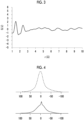
- Fig. 4 shows an example of the spectrum obtained in a case where the solid 7 Li-NMR measurement of the solid electrolyte (I) is performed at 20°C or 120°C.
- the spectrum shown on the lower side by the solid line in Fig. 4 is a spectrum obtained in a case where the solid 7 Li-NMR measurement is performed at 20°C; and the spectrum shown on the upper side by the broken line in Fig. 4 is a spectrum obtained in a case where the solid 7 Li-NMR measurement is performed at 120°C.
- the peak to be obtained is a sharper peak.
- the spectrum at 20°C and the spectrum at 120°C are compared, the spectrum at 120°C is sharper. That is, in the aspect shown in Fig. 4 , it is indicated that the mobility of Li + is high due to the presence of Li defects. It is conceived that such a solid electrolyte (I) is likely to be plastically deformed due to the above-described defect structure, and thus has excellent hopping property of Li + .
- the spectrum measured at 20°C shown by the solid line, shown on the lower side of Fig. 5 , and the spectrum measured at 120°C shown by the broken line, shown on the upper side of Fig. 5 tends to have substantially the same shape. That is, the lithium tetraborate crystal has no Li defects and the like, and as a result, it has a high elastic modulus and is hardly plastically deformed.
- the measurement is performed by a single pulse method using a 4 mm HX CP-MAS probe, 90° pulse width: 3.2 ⁇ s, observation frequency: 155.546 MHz, observation width: 1397.6 ppm, repetition time: 15 sec, integration: 1 time, and MAS rotation speed: 0 Hz.
- the solid electrolyte (I) used in the present invention in a case where a first peak appearing in a range of -100 to +100 ppm in the spectrum obtained in a case where the solid 7 Li-NMR measurement is performed at 20°C is waveform-separated, it is preferable that a second peak having a full-width at half maximum of 5 ppm or less appears in a range with a chemical shift of -3 to +3 ppm, and a proportion of an area intensity of the second peak to an area intensity of the first peak is 0.5% or more.
- the above-described proportion of the area intensity is more preferably 2% or more, still more preferably 5% or more, particularly preferably 10% or more, and most preferably 15% or more.
- the solid electrolyte (I) contains water
- the solid 7 Li-NMR spectral characteristics of the solid electrolyte (I) tend to be as described above.
- the upper limit of the above-described proportion of the area intensity is not particularly limited, but is usually 50% or less.
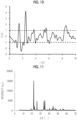
- Fig. 6 shows an example of the spectrum obtained in a case where the solid 7 Li-NMR measurement of the solid electrolyte (I) is performed at 20°C.
- a peak (corresponding to the first peak) is observed in a range of -100 to +100 ppm, and a small peak is observed in the vicinity of a chemical shift of 0 ppm, as shown by the broken line at the first peak.
- it is considered to be affected the fact that a sharp peak is observed in a case where the mobility of Li + is high.
- Fig. 7 shows a diagram in a case where the first peak is waveform-separated.
- the first peak is waveform-separated into a small peak (corresponding to the second peak) represented by the solid line, and a large peak represented by the broken line.
- the above-described second peak is a peak which appears in a range with a chemical shift of -3 to +3 ppm, and has a full-width at half maximum of 5 ppm or less.
- the proportion of the area intensity of the second peak shown by the solid line in Fig. 7 to the area intensity of the first peak (peak before the waveform separation) shown in Fig. 6 ⁇ (Area intensity of second peak/Area intensity of first peak) ⁇ 100 (%) ⁇ is within the above-described range.
- Examples of the method of waveform separation include a method using a known software, and examples of the software include Igor Pro, which is graph processing software manufactured by WaveMetrics, Inc.
- a coefficient of determination which is obtained by performing linear regression analysis according to a least-squares method in a wave number range of 600 to 850 cm -1 in a Raman spectrum of the solid electrolyte (I), is preferably 0.9400 or more and more preferably 0.9600 or more, and also preferably 0.9800 or more.
- the upper limit thereof is not particularly limited, but is usually 1.0000 or less.
- a Raman spectrum of the solid electrolyte (I) is acquired.
- Raman imaging is performed as the measuring method of the Raman spectrum.
- the Raman imaging is a microscopic spectroscopy method which combines Raman spectroscopy with a microscopic technique.
- the Raman imaging is a method of scanning a sample with excitation light to detect measurement light including Raman scattered light, and then visualizing distribution or the like of components based on the intensity of the measurement light.
- the measurement conditions for the Raman imaging are as follows: an environment of atmospheric air of 27°C, an excitation light of 532 nm, an objective lens of 100 magnifications, a point scanning according to the mapping method, a step of 1 ⁇ m, an exposure time per point of 1 second, the number of times of integration of 1, and a measurement range of a range of 70 ⁇ m ⁇ 50 ⁇ m.
- the measurement range may be narrower depending on a film thickness of the sample.
- the Raman spectrum data is subjected to a principal component analysis (PCA) processing to remove noise.
- PCA principal component analysis
- the spectrum is recombined using components having an autocorrelation coefficient of 0.6 or more.
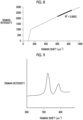
- Fig. 8 shows an example of the Raman spectrum of the solid electrolyte (I).
- the vertical axis indicates the Raman intensity
- the lateral axis indicates the Raman shift.
- a coefficient of determination (coefficient of determination R 2 ) obtained by performing linear regression analysis according to a least-squares method is calculated in a wave number range of 600 to 850 cm -1 of the Raman spectrum shown in Fig. 8 . That is, in a wave number range of 600 to 850 cm -1 in the Raman spectrum of Fig. 8 , a regression line (the thick broken line in Fig. 8 ) is determined according to the least-squares method, and the coefficient of determination R 2 of the regression line is calculated. As the coefficient of determination, a value between 0 (no linear correlation) and 1 (complete linear correlation of the measured values) is taken according to the linear correlation of the measured values.
- the above-described coefficient of determination R 2 corresponds to the square of the correlation coefficient (Pearson's product-moment correlation coefficient). More specifically, in the present specification, the coefficient of determination R 2 is calculated according to the following expression.
- x 1 and y 1 represent a wave number in the Raman spectrum and a Raman intensity corresponding to the wave number;
- x 2 represents the (arithmetic) average of the wave numbers;
- y 2 represents the (arithmetic) average of the Raman intensities.
- R 2 ⁇ x 1 - x 2 ⁇ y 1 - y 2 2 ⁇ x 1 - x 2 2 ⁇ ⁇ y 1 - y 2 2
- Fig. 9 shows a Raman spectrum of a general lithium tetraborate crystal.
- a general lithium tetraborate crystal peaks are observed in a wave number range of 716 to 726 cm -1 and a wave number range of 771 to 785 cm -1 , derived from the structure thereof.
- the coefficient of determination thereof is less than 0.9400 in a case where the coefficient of determination is calculated by performing linear regression analysis according to a least-squares method in a wave number range of 600 to 850 cm -1 .
- a value of a ratio of a maximum absorption intensity in a wave number range of 3,000 to 3,500 cm -1 to a maximum absorption intensity in a wave number range of 800 to 1,600 cm -1 is preferably 1/5 or more (0.2 or more).
- the above-described ratio is preferably 3/10 or more and more preferably 2/5 or more.
- the upper limit thereof is not particularly limited, but is preferably 1 or less.
- an O-H stretching vibration mode is observed in a wave number range of 3,000 to 3,500 cm -1
- a B-O stretching vibration mode is observed in a wave number range of 800 to 1,600 cm -1 .
- the solid electrolyte (I) a strong absorption intensity derived from the O-H stretching vibration mode is observed, and it is confirmed that a large number of OH groups and/or a large amount of water are contained.
- lithium ions tend to move easily, and as a result, the ion conductivity tends to be improved.
- the measurement is performed using objective lens: Cassegrain type (NA: 0.65) of 32 magnifications, detector: MCT-A, measurement range: 650 to 4,000 cm -1 , resolution: 4 cm -1 , and sample cell: diamond cell.
- objective lens Cassegrain type (NA: 0.65) of 32 magnifications
- detector MCT-A
- measurement range 650 to 4,000 cm -1
- resolution 4 cm -1
- sample cell diamond cell.
- the obtained infrared absorption spectrum is subjected to correction for removing signals derived from water and CO 2 in the air, and the background is further subjected to offset-correction to set the absorption intensity to 0.
- the measurement is performed in the air after vacuum drying at 40°C for 2 hours.
- the ion conductivity (27°C) of the solid electrolyte (I) is not particularly limited, and from the viewpoint of application to various applications, it is preferably 1.0 ⁇ 10 -5 S/cm or more, more preferably 1.0 ⁇ 10 -4 S/cm or more, still more preferably 1.0 ⁇ 10 -3 S/cm or more, and particularly preferably 3.0 ⁇ 10 -3 S/cm or more.
- the upper limit thereof is not particularly limited, but is usually 1.0 ⁇ 10 -2 S/cm or less.
- the solid electrolyte (I) exhibits the following characteristics or physical properties.
- a mass reduction rate in a case where the solid electrolyte (I) is heated to 800°C is preferably 20% to 40% by mass and more preferably 25% to 35% by mass. It is considered that the mass reduction by the above-described heating is due to removal of moisture contained in the solid electrolyte (I). In a case where the solid electrolyte (I) contains such moisture, the conductivity of lithium ions can be further improved.
- the heating is performed at a temperature rising rate of 20 °C/sec in a range of 25°C to 800°C.
- a known thermogravimetric differential thermal analysis (TG-DTA) device can be used for measuring the mass reduction rate.
- the above-described mass reduction rate is calculated by ⁇ (Mass at 25°C - Mass at 800°C)/Mass at 25°C ⁇ ⁇ 100.
- the solid electrolyte (I) is subjected to vacuum drying at 40°C for 2 hours in advance. In addition, the measurement of the mass reduction rate is performed in the air.
- the solid electrolyte layer constituting the secondary battery according to the embodiment of the present invention may contain other components in addition to the solid electrolyte (I).
- the solid electrolyte layer can contain a binder consisting of an organic polymer.
- the organic polymer constituting the binder may be in a particle shape or may be in a non-particle shape.
- the solid electrolyte layer may contain a solid electrolyte other than the solid electrolyte (I).
- the other solid electrolyte means a solid electrolyte in which lithium ions can be moved therein.
- the solid electrolyte is preferably an inorganic solid electrolyte.
- Examples of the other solid electrolytes include an oxide-based solid electrolyte, a halide-based solid electrolyte, and a hydride-based solid electrolyte; and an oxide-based solid electrolyte is preferable.
- a thickness of the solid electrolyte layer constituting the secondary battery according to the embodiment of the present invention is not particularly limited, and can be set to, for example, 10 to 1,000 ⁇ m, preferably 50 to 400 ⁇ m.
- the thickness thereof can be set to 0.1 to 50 ⁇ m, and in this case, it is preferably 1 to 20 ⁇ m.
- the positive electrode layer generally includes a positive electrode collector layer and a positive electrode active material layer, but may be composed of the positive electrode active material layer, not including the positive electrode collector layer.
- the positive electrode active material layer also functions as the positive electrode collector layer, it is not necessary to be composed of two layers of the positive electrode active material layer and the positive electrode collector layer, and a single layer configuration may be adopted.
- the positive electrode active material layer generally contains a solid electrolyte (preferably an inorganic solid electrolyte) together with a positive electrode active material, but may not contain the solid electrolyte.
- a solid electrolyte preferably an inorganic solid electrolyte
- the type of the solid electrolyte is not particularly limited. From the viewpoint of achieving both flexibility and safety at a high level, it is preferable to use the above-described solid electrolyte (I). In this manner, the solid electrolyte (I) also acts as a binder of solid particles contained in the positive electrode layer, and thus the positive electrode layer can be made to have higher flexibility.
- the positive electrode active material layer may contain one or two or more kinds of solid electrolytes.
- a content of the solid electrolyte in the positive electrode active material layer is not particularly limited, and is preferably 50% to 99.9% by mass, more preferably 70% to 99.5% by mass, and still more preferably 90% to 99% by mass, as the total content of the solid electrolyte and the positive electrode active material.
- the positive electrode active material used in the positive electrode layer a positive electrode active material which can be used for a typical lithium ion secondary battery can be widely used. A suitable aspect of the positive electrode active material will be described below.
- the positive electrode active material a positive electrode active material capable of reversibly intercalating and/or deintercalating lithium ions is preferable.
- the positive electrode active material is not particularly limited, and is preferably a transition metal oxide and more preferably a transition metal oxide containing a transition metal element Ma (one or more kinds of elements selected from Co, Ni, Fe, Mn, Cu, and V).
- an element Mb an element of Group 1 (Ia) of the periodic table other than lithium, an element of Group 2 (IIa), or an element such as Al, Ga, In, Ge, Sn, Pb, Sb, Bi, Si, P, or B
- an element Mb an element of Group 1 (Ia) of the periodic table other than lithium, an element of Group 2 (IIa)
- the amount of the Mb mixed is preferably 0 to 30 mol% with respect to the amount (100 mol%) of the transition metal element Ma. It is more preferable that the transition metal oxide is synthesized by mixing the above-described components such that a molar ratio Li/Ma is 0.3 to 2.2.
- transition metal oxides having a bedded salt-type structure include (MA) transition metal oxides having a bedded salt-type structure, (MB) transition metal oxides having a spinel-type structure, (MC) lithium-containing transition metal phosphoric acid compounds, (MD) lithium-containing transition metal halogenated phosphoric acid compounds, and (ME) lithium-containing transition metal silicate compounds.
- MA transition metal oxides having a bedded salt-type structure
- MB transition metal oxides having a spinel-type structure
- MC lithium-containing transition metal phosphoric acid compounds
- MD lithium-containing transition metal halogenated phosphoric acid compounds
- ME lithium-containing transition metal silicate compounds.
- transition metal oxide having a bedded salt-type structure examples include LiCoO 2 (lithium cobalt oxide [LCO]), LiNi 2 O 2 (lithium nickelate), LiNi 0.85 Co 0.10 Al 0.05 O 2 (lithium nickel cobalt aluminum oxide [NCA]), LiNi 1/3 Co 1/3 Mn 1/3 O 2 (lithium nickel manganese cobalt oxide [NMC]), and LiNi 0.5 Mn 0.5 O 2 (lithium manganese nickelate).
- LiCoO 2 lithium cobalt oxide [LCO]
- LiNi 2 O 2 lithium nickelate
- LiNi 0.85 Co 0.10 Al 0.05 O 2 lithium nickel cobalt aluminum oxide [NCA]
- LiNi 1/3 Co 1/3 Mn 1/3 O 2 lithium nickel manganese cobalt oxide [NMC]
- LiNi 0.5 Mn 0.5 O 2 lithium manganese nickelate
- transition metal oxide having a spinel-type structure examples include LiMn 2 O 4 (LMO), LiNi 0.5 Mn 1.5 O 4 ([LNMO]), LiCoMnO 4 , Li 2 FeMn 3 O 8 , Li 2 CuMn 3 O 8 , Li 2 CrMn 3 O 8 , and Li 2 NiMn 3 O 8 .
- lithium-containing transition metal phosphoric acid compound examples include olivine-type iron phosphate salts such as LiFePO 4 ([LFP]) and Li 3 Fe 2 (PO 4 ) 3 ; iron pyrophosphates such as LiFeP 2 O 7 ; cobalt phosphates such as LiCoPO 4 ; cobalt pyrophosphates such as Li 2 CoP 2 O 7 ; and monoclinic NASICON-type vanadium phosphate salts such as Li 3 V 2 (PO 4 ) 3 (lithium vanadium phosphate).
- olivine-type iron phosphate salts such as LiFePO 4 ([LFP]) and Li 3 Fe 2 (PO 4 ) 3
- iron pyrophosphates such as LiFeP 2 O 7
- cobalt phosphates such as LiCoPO 4
- cobalt pyrophosphates such as Li 2 CoP 2 O 7
- monoclinic NASICON-type vanadium phosphate salts such as Li
- lithium-containing transition metal halogenated phosphoric acid compound examples include iron fluorophosphates such as Li 2 FePO 4 F, manganese fluorophosphates such as Li 2 MnPO 4 F, and cobalt fluorophosphates such as Li 2 CoPO 4 F.
- lithium-containing transition metal silicate compound (ME) examples include Li 2 FeSiO 4 , Li 2 MnSiO 4 , and Li 2 CoSiO 4 .
- the collector layer constituting the positive electrode layer is an electron conductor.
- the positive electrode collector layer is usually in a form of a film sheet.
- Examples of a constitutional material of the positive electrode collector layer include aluminum (Al), an aluminum alloy (Al alloy), copper (Cu), stainless steel, nickel, and titanium; and aluminum, an aluminum alloy, copper (Cu), or titanium is preferable and aluminum, an aluminum alloy, or copper (Cu) is more preferable.
- Examples of the positive electrode collector layer also include a collector layer having a coating layer (thin film) of carbon, nickel, titanium, aluminum, or silver on a surface of aluminum or stainless steel.
- Al alloy examples include an Al-Cu-based alloy (approximately 500°C to 640°C), an Al-Mn-based alloy (approximately 640°C), an Al-Si-based alloy (approximately 530°C to 570°C), an Al-Mg-based alloy (approximately 570°C to 650°C), an Al-Mg-Si-based alloy (approximately 580°C to 650°C), and an Al-Zn-Mg-based alloy (approximately 480°C to 640°C). Temperatures in the parentheses all mean a melting point at normal pressure.
- a thickness of the positive electrode active material layer constituting the secondary battery according to the embodiment of the present invention is not particularly limited, and can be set to, for example, 5 to 500 ⁇ m, preferably 20 to 200 ⁇ m.
- the thickness thereof can be set to 0.1 to 50 ⁇ m, and in this case, it is preferably 1 to 20 ⁇ m.
- a thickness of the positive electrode collector layer constituting the secondary battery according to the embodiment of the present invention is not particularly limited, and can be set to, for example, 10 to 100 ⁇ m, preferably 10 to 50 ⁇ m.
- the thickness thereof can be set to 0.01 to 20 ⁇ m, and in this case, it is preferably 0.05 to 10 ⁇ m and more preferably 0.1 to 5 ⁇ m.
- the negative electrode layer generally includes a negative electrode collector layer and a negative electrode active material layer, but may be composed of the negative electrode active material layer, not including the negative electrode collector layer.
- the negative electrode active material layer also functions as the negative electrode collector layer, it is not necessary to be composed of two layers of the negative electrode active material layer and the negative electrode collector layer, and a single layer configuration may be adopted.
- the negative electrode active material layer generally contains a solid electrolyte (preferably an inorganic solid electrolyte) together with a negative electrode active material, but may not contain the solid electrolyte.
- a solid electrolyte preferably an inorganic solid electrolyte
- the type of the solid electrolyte is not particularly limited. From the viewpoint of achieving both flexibility and safety at a high level, it is preferable to use the above-described solid electrolyte (I). In this manner, the solid electrolyte (I) also acts as a binder of solid particles contained in the negative electrode layer, and thus the negative electrode layer can be made to have higher flexibility.
- the negative electrode active material layer may contain one or two or more kinds of solid electrolytes.
- a content of the solid electrolyte in the negative electrode active material layer is not particularly limited, and is preferably 50% to 99.9% by mass, more preferably 70% to 99.5% by mass, and still more preferably 90% to 99% by mass, as the total content of the solid electrolyte and the negative electrode active material.
- the negative electrode active material used in the negative electrode layer a negative electrode active material which can be used for a typical lithium ion secondary battery can be widely used. A suitable aspect of the negative electrode active material will be described below.
- a negative electrode active material capable of reversibly intercalating and deintercalating lithium ions is preferable.
- the negative electrode active material is not particularly limited, and examples thereof include a carbonaceous material, an oxide of a metal element or a metalloid element, a lithium single substance, a lithium alloy, and a negative electrode active material capable of forming an alloy with lithium.
- the carbonaceous material used as the negative electrode active material is a material substantially consisting of carbon.
- Examples thereof include petroleum pitch; carbon black such as acetylene black (AB); graphite (natural graphite and artificial graphite such as vapor-grown graphite); and carbonaceous material obtained by baking various synthetic resins such as a polyacrylonitrile (PAN)-based resin and a furfuryl alcohol resin.
- PAN polyacrylonitrile
- examples thereof also include various carbon fibers such as PAN-based carbon fiber, cellulose-based carbon fiber, pitch-based carbon fiber, vapor-grown carbon fiber, dehydrated polyvinyl alcohol (PVA)-based carbon fiber, lignin carbon fiber, vitreous carbon fiber, and activated carbon fiber; mesophase microspheres, graphite whisker, and tabular graphite.
- PAN-based carbon fiber cellulose-based carbon fiber
- pitch-based carbon fiber vapor-grown carbon fiber
- PVA dehydrated polyvinyl alcohol
- lignin carbon fiber lignin carbon fiber
- vitreous carbon fiber vitreous carbon fiber
- activated carbon fiber activated carbon fiber
- mesophase microspheres mesophase microspheres
- graphite whisker and tabular graphite.
- carbonaceous materials can be classified into non-graphitizable carbonaceous materials (also referred to as "hard carbon”) and graphitizable carbonaceous materials, based on the graphitization degree.
- the carbonaceous material has a surface spacing, density, or crystallite size described in JP1987-022066A ( JP-S62-022066A ), JP1990-006856A ( JP-H2-006856A ), and JP1991-045473A ( JP-H3-045473A ).
- the carbonaceous material is not necessarily a single material, and for example, may be a mixture of natural graphite and artificial graphite described in JP1993-090844A ( JP-H5-090844A ) or graphite having a coating layer described in JP1994-004516A ( JP-H6-004516A ).
- the carbonaceous material is preferably hard carbon or graphite, and more preferably graphite.
- the oxide of a metal element or a metalloid element, which can be used as the negative electrode active material, is not particularly limited as long as it is an oxide capable of intercalating and deintercalating lithium; and examples thereof include an oxide of a metal element (metal oxide) such as Fe 3 O 4 , a composite oxide of a metal element, a composite oxide of a metal element and a metalloid element, and an oxide of a metalloid element (a metalloid oxide).
- the composite oxide of a metal element and the composite oxide of a metal element and a metalloid element are also collectively referred to as a metal composite oxide.
- These oxides are preferably a noncrystalline oxide, and also preferably a chalcogenide which is a reaction product between a metal element and an element of Group 16 of the periodic table.
- the metalloid element refers to an element having intermediate properties between those of a metal element and a non-metalloid element, and typically, the metalloid element includes six elements including boron, silicon, germanium, arsenic, antimony, and tellurium, and further includes three elements including selenium, polonium, and astatine.
- noncrystalline means an oxide having a broad scattering band with an apex in a range of 20° to 40° in terms of the 2 ⁇ value in case of being measured by an X-ray diffraction method using a CuK ⁇ ray, and the oxide may have a crystalline diffraction line.
- the highest intensity in a crystalline diffraction line observed in a range of 40° to 70° in terms of the 2 ⁇ value is preferably 100 times or less and more preferably 5 times or less with respect to the intensity of a diffraction line at the apex in a broad scattering band observed in a range of 20° to 40° in terms of the 2 ⁇ value, and it is still more preferable that the oxide does not have a crystalline diffraction line.
- the noncrystalline oxide of a metalloid element or the above-described chalcogenide is more preferable; and a (composite) oxide consisting of one element or a combination of two or more elements selected from elements (for example, Al, Ga, Si, Sn, Ge, Pb, Sb, and Bi) of Group 13 (IIIB) to Group 15 (VB) of the periodic table or the chalcogenide is particularly preferable.
- the noncrystalline oxide and the chalcogenide are preferably Ga 2 O 3 , GeO, PbO, PbO 2 , Pb 2 O 3 , Pb 2 O 4 , Pb 3 O 4 , Sb 2 O 3 , Sb 2 O 4 , Sb 2 O 8 Bi 2 O 3 , Sb 2 O 8 Si 2 O 3 , Sb 2 O 5 , Bi 2 O 3 , Bi 2 O 4 , GeS, PbS, PbS 2 , Sb 2 S 3 , or Sb 2 S 5 .
- a negative electrode active material which can be used in combination with the noncrystalline oxide negative electrode active material mainly using Sn, Si, or Ge, a carbonaceous material capable of intercalating and deintercalating lithium ions or lithium metal, a lithium single substance, a lithium alloy, or a negative electrode active material capable of forming an alloy with lithium is preferable.
- the oxide of a metal element or a metalloid element (particularly, the metal (composite) oxide) and the above-described chalcogenide contains at least one of titanium or lithium as a constitutional component.
- metal composite oxide containing lithium examples include a composite oxide of lithium oxide and the above-described metal composite oxide or the above-described chalcogenide. More specific examples thereof include Li 2 SnO 2 .
- the negative electrode active material for example, the metal oxide
- a titanium oxide a titanium oxide
- Li 4 Ti 5 O 12 lithium titanium oxide [LTO]
- LTO lithium titanium oxide
- the lithium alloy as the negative electrode active material is not particularly limited as long as it is typically used as a negative electrode active material for an all-solid-state lithium ion secondary battery, and examples thereof include a lithium aluminum alloy.
- the negative electrode active material capable of forming an alloy with lithium is not particularly limited as long as it is typically used as a negative electrode active material for an all-solid-state lithium ion secondary battery.
- Examples of the above-described negative electrode active material include a negative electrode active material (alloy) containing a silicon element or a tin element and a metal such as Al and In; and a negative electrode active material containing a silicon element (silicon element-containing active material) capable of exhibiting high battery capacity is preferable, and a silicon element-containing active material in which a content of the silicon element is 50 mol% or more with respect to all constitutional elements is more preferable.
- a negative electrode containing the negative electrode active material for example, an Si negative electrode containing the silicon element-containing active material or an Sn negative electrode containing an active material containing a tin element
- a carbon negative electrode for example, graphite or acetylene black
- the silicon element-containing active material examples include a silicon-containing alloy (for example, LaSi 2 , VSi 2 , La-Si, Gd-Si, or Ni-Si) containing a silicon material such as Si and SiO x (0 ⁇ x ⁇ 1) and further containing titanium, vanadium, chromium, manganese, nickel, copper, or lanthanum; and a structured active material thereof (for example, LaSi 2 /Si).
- examples thereof include an active material containing a silicon element and a tin element, such as SnSiO 3 and SnSiS 3 .
- SiO x itself can be used as the negative electrode active material (the metalloid oxide) and Si is produced along with the operation of the all-solid-state lithium ion secondary battery, SiO x can be used as a negative electrode active material (or a precursor material thereof) capable of forming an alloy with lithium.
- Examples of the negative electrode active material containing a tin element include Sn, SnO, SnO 2 , SnS, SnS 2 , and the above-described active material containing a silicon element and a tin element.
- the negative electrode active material is preferably the negative electrode active material capable of forming an alloy with lithium, more preferably the above-described silicon material or the above-described silicon-containing alloy (alloy containing a silicon element), and still more preferably silicon (Si) or a silicon-containing alloy.
- titanium niobium composite oxide As the negative electrode active material, it is also preferable to use a titanium niobium composite oxide as the negative electrode active material. It is expected that the titanium niobium composite oxide has a high theoretical volume capacity density, long life, and possibility of rapid charging. Examples of the titanium niobium composite oxide include TiNb 2 O 7 ([TNO]).
- a shape of the negative electrode active material is not particularly limited, but is preferably a particle shape.
- a volume average particle size of the negative electrode active material is not particularly limited, and it is preferably 0.1 to 60 ⁇ m, more preferably 0.5 to 20 ⁇ m, and still more preferably 1.0 to 15 ⁇ m.
- the volume average particle size is measured according to the following procedure.
- the negative electrode active material is diluted in a 20 mL sample bottle to prepare a 1% by mass dispersion liquid.
- the diluted dispersion liquid sample is irradiated with 1 kHz ultrasonic waves for 10 minutes, and then immediately used for test.
- Data collection is performed 50 times with the dispersion liquid sample using a laser diffraction/scattering-type particle size distribution analyzer and a quartz cell for measurement at a temperature of 25°C, thereby obtaining the volume average particle size.
- Other detailed conditions and the like can be found in JIS Z 8828: 2013 "Particle Diameter Analysis-Dynamic Light Scattering", as necessary. Five samples are produced for each level, and the average value thereof is adopted.
- One kind of the negative electrode active material may be used alone, or two or more kinds thereof may be used in combination.
- a content of the negative electrode active material in the negative electrode active material layer is not particularly limited, and is preferably 10% to 90% by mass, more preferably 20% to 85% by mass, still more preferably 30% to 80% by mass, and particularly preferably 35% to 75% by mass.
- a surface of the negative electrode active material may be coated with an oxide such as another metal oxide and a carbon-based material. These surface coating layers can function as an interface resistance-stabilizing layer.
- the surface coating agent examples include a metal oxide containing Ti, Nb, Ta, W, Zr, Al, Si, or Li.
- examples thereof include titanium oxide spinel, tantalum-based oxides, niobium-based oxides, and lithium niobate-based compounds; and specific examples thereof include Li 4 T 15 O 12 , Li 2 Ti 2 O 5 , LiTaO 3 , LiNbO 3 , LiAlO 2 , Li 2 ZrO 3 , Li 2 WO 4 , Li 2 TiO 3 , Li 2 B 4 O 7 , Li 3 PO 4 , Li 2 MoO 4 , Li 3 BO 3 , LiBO 2 , Li 2 CO 3 , Li 2 SiO 3 , SiO 2 , TiO 2 , ZrO 2 , Al 2 O 3 , B 2 O 3 , and Li 3 AlF 6 .
- a carbon-based material such as C, SiC, and SiOC (carbon-added silicon oxide) can also be used as the surface coating material.
- the surface of the negative electrode active material may be subjected to a surface treatment with sulfur or phosphorus.
- the surface of the negative electrode active material may be subjected to a surface treatment with an actinic ray or an active gas (for example, plasma) before or after the above-described surface coating.
- an actinic ray or an active gas for example, plasma
- the negative electrode active material TiNb 2 O 7 (TNO), Li 4 Ti 5 O 12 (LTO), Fe 3 O 4 , or an active material in which these substances are coated with the interface resistance-stabilizing layer such as an oxide and a carbon-based material is preferable.
- the collector layer constituting the negative electrode layer is an electron conductor.
- the negative electrode collector layer is usually in a form of a film sheet.
- Examples of a constitutional material of the negative electrode collector layer include aluminum, an aluminum alloy, copper, a copper alloy, stainless steel, nickel, zinc, and titanium; and aluminum, an aluminum alloy, or copper is preferable.
- Examples of the negative electrode collector layer also include a collector layer having a coating layer (thin film) of carbon, nickel, zinc, titanium, aluminum, gold, or silver on a surface of aluminum, copper, a copper alloy, or stainless steel.
- a thickness of the negative electrode active material layer constituting the secondary battery according to the embodiment of the present invention is not particularly limited, and can be set to, for example, 5 to 500 ⁇ m, preferably 20 to 200 ⁇ m.
- the thickness thereof can be set to 0.1 to 50 ⁇ m, and in this case, it is preferably 1 to 20 ⁇ m.
- a thickness of the negative electrode collector layer constituting the secondary battery according to the embodiment of the present invention is not particularly limited, and can be set to, for example, 10 to 100 ⁇ m, preferably 10 to 50 ⁇ m.
- the thickness thereof can be set to 0.01 to 20 ⁇ m, and in this case, it is preferably 0.05 to 10 ⁇ m and preferably 0.1 to 5 ⁇ m.
- At least one of the positive electrode layer or the negative electrode layer includes a collector layer, and at least one collector layer is a layer having, as a constitutional material, a metal melted at 670°C under normal pressure or a layer having the metal in a coating layer.
- the "metal melted at 670°C under normal pressure” means a metal which is melted at 670°C under a pressure condition of 101.33 kPa, and means a metal having a melting point of 670°C or lower under normal pressure.
- metal melted at 670°C under normal pressure examples include Al (melting point under normal pressure: approximately 650°C to 660°C) and an Al alloy (melting point under normal pressure: approximately 480°C to 650°C) described in the positive electrode collector layer above; and Al (melting point under normal pressure: approximately 650°C to 660°C) described in the negative electrode collector layer above.
- the all-solid-state lithium ion secondary battery using the oxide-based solid electrolyte in the related art aluminum or an aluminum alloy may be used as a constitutional material of the collector layer or a material used in the coating layer.
- the all-solid-state lithium ion secondary battery using the oxide-based solid electrolyte in the related art which has a collector layer having aluminum or an aluminum alloy as a constituent material or a collector layer having the metal in the coating layer, has not been able to exist.
- the positive electrode layer and the negative electrode layer may contain a component (other components) other than the solid electrolyte and the active material in the active material layers.
- a conductive auxiliary agent can be contained.
- a conductive auxiliary agent which is known as a general conductive auxiliary agent can be used.
- the conductive auxiliary agent include graphite such as natural graphite and artificial graphite, carbon black such as acetylene black, Ketjen black, and furnace black, amorphous carbon such as needle cokes, carbon fiber such as vapor-grown carbon fiber and carbon nanotube, and a carbonaceous material such as graphene and fullerene, which are electron-conductive materials.
- a conductive polymer such as polyaniline, polypyrrole, polythiophene, polyacetylene, and a polyphenylene derivative may also be used.
- a general conductive auxiliary agent containing no carbon atom such as metal powder and metal fiber, may be used.
- the conductive auxiliary agent refers to a conductive auxiliary agent which does not cause the intercalation and deintercalation of Li at the time of charging and discharging of the battery, and does not function as an active material.
- a conductive auxiliary agent which can function as the active material in the active material layer at the time of charging and discharging of the battery is classified as the active material, not as the conductive auxiliary agent.
- the conductive auxiliary agent functions as the active material at the time of charging and discharging of the battery is not unambiguously determined, and determined by a combination with the active material.
- a content of the conductive auxiliary agent in the positive electrode active material layer is not particularly limited, and it is, for example, preferably 0% to 10% by mass and more preferably 1% to 5% by mass.
- a content of the conductive auxiliary agent in the negative electrode active material layer is not particularly limited, and it is, for example, preferably 0% to 10% by mass and more preferably 1% to 5% by mass.
- Examples of the other components also include the above-described binder and lithium salt.
- the secondary battery according to the embodiment of the present invention can be manufactured with reference to a general manufacturing method for an all-solid-state secondary battery, except that the solid electrolyte (I) is used in at least the solid electrolyte layer, at least one of the positive electrode layer or the negative electrode layer includes a collector layer, and a layer having a specific metal as a constitutional material or a layer having the metal in a coating layer is used as at least one collector layer. That is, the manufacturing method of the secondary battery according to the embodiment of the present invention can be performed by including a step of obtaining a laminate in which a positive electrode layer, a solid electrolyte layer, and a negative electrode layer are arranged in this order.
- an amount of water used in the solid electrolyte (I) may satisfy or not satisfy the amount specified in the present invention.
- the amount of water used in the solid electrolyte (I) is not regarded; but in order to set the amount of water of the solid electrolyte (I) contained in the constitutional layer such as the solid electrolyte layer to the amount specified in the present invention, in the manufacturing of the secondary battery according to the embodiment of the present invention, a step of subjecting the formed solid electrolyte layer to a drying treatment can also be included as necessary.
- the drying step of the constitutional layer such as the solid electrolyte layer may be performed at any stage after the constitutional layer such as the solid electrolyte layer is formed, as long as the solid electrolyte (I) of the constitutional layer such as the solid electrolyte layer in the secondary battery to be obtained can be set to the water amount specified in the present invention.
- the drying method is not particularly limited, and for example, the water amount of the solid electrolyte (I) in the solid electrolyte layer can be reduced to within the range specified in the present invention by using a desiccator, subjecting the solid electrolyte layer to vacuum drying, subjecting the solid electrolyte layer to freeze vacuum drying, or subjecting the solid electrolyte layer to a heating treatment.
- the secondary battery according to the embodiment of the present invention is preferably obtained by sealing the above-described laminate in which the positive electrode layer, the solid electrolyte layer, and the negative electrode layer are arranged in this order.
- the sealing it is possible to more reliably prevent the mixing of moisture into the solid electrolyte layer after the above-described drying step, and thus it is possible to further improve the cycle characteristics.
- the sealing method is not particularly limited as long as the mixing of moisture (atmosphere) can be blocked or suppressed.
- Examples thereof include a method of sealing the above-described laminate in which the positive electrode layer, the solid electrolyte layer, and the negative electrode layer are arranged in this order by closing a lid of a housing (battery cell) storing the laminate using a gasket such as an O-ring. Furthermore, cell resistance can also be improved by heating the obtained laminate (for example, at 80°C for 2 hours).
- At least one collector layer included in at least one of the positive electrode layer or the negative electrode layer is a layer having, as a constitutional material, a metal melted at 670°C under normal pressure or a layer having the metal in a coating layer.
- the solid electrolyte layer contains the solid electrolyte (I) and the high-temperature sintering treatment is not required, as the metal used as a constitutional material of the collector layer or contained in the coating layer, a metal melted at 670°C under normal pressure, which is difficult to use in the oxide-based solid electrolyte in the related art, can be used.
- the metal melted at 670°C under normal pressure is as described above.
- At least one collector layer included in at least one of the positive electrode layer or the negative electrode layer is a layer having Cu as a constitutional material or a layer having Cu in a coating layer, and the laminate of the positive electrode layer, the solid electrolyte layer, and the negative electrode layer is manufactured at 300°C or lower in an atmosphere containing oxygen gas.
- the solid electrolyte layer contains the solid electrolyte (I) and the high-temperature sintering treatment is not required, as the metal used as a constitutional material of the collector layer or contained in the coating layer, Cu oxidized under high temperature conditions with oxygen gas, which is difficult to use in the oxide-based solid electrolyte in the related art, can be used even in an atmosphere containing oxygen gas. In a case of manufacturing at 300°C or lower in the atmosphere containing oxygen gas, oxidation of Cu can be suppressed depending on conditions such as a heating time and a heating temperature.
- Examples of the atmosphere containing oxygen gas generally include air.
- a content concentration of the oxygen gas is not particularly limited, and the upper limit value thereof can be set to 100 vol% or less and the lower limit value thereof can be set to, for example, 1 vol% or more.
- the secondary battery according to the embodiment of the present invention can be manufactured by a manufacturing step at 300°C or lower in an atmosphere containing oxygen gas, and it can be manufactured in an atmosphere containing oxygen gas, preferably at 200°C or lower, more preferably 120°C or lower, and still more preferably 100°C or lower.
- the manufacturing can be performed in an atmosphere containing oxygen gas, preferably at 80°C or lower, more preferably 60°C, still more preferably 40°C, and particularly preferably under a condition in which heating is not performed (for example, room temperature of 20°C to 27°C).
- atmosphere containing oxygen gas preferably at 80°C or lower, more preferably 60°C, still more preferably 40°C, and particularly preferably under a condition in which heating is not performed (for example, room temperature of 20°C to 27°C).
- a method of forming the laminate in which the positive electrode layer, the solid electrolyte layer, and the negative electrode layer are arranged in this order is not particularly limited.
- Examples of the manufacturing method of the all-solid-state secondary battery include a method in which a composition for forming a positive electrode (positive electrode slurry) containing a positive electrode active material is applied onto a metal foil which is a positive electrode collector layer to form a positive electrode active material layer, a dispersion liquid for forming a solid electrolyte layer (solid electrolyte slurry) containing a solid electrolyte is applied onto the positive electrode active material layer to form a solid electrolyte layer, a composition for forming a negative electrode (negative electrode slurry) containing a negative electrode active material is applied onto the solid electrolyte layer to form a negative electrode active material layer, and a negative electrode collector layer (metal foil) is laminated on the negative electrode active material layer.
- the entire laminate is optionally subjected to a pressurization treatment to obtain the all-solid-state lithium ion secondary battery as shown in Fig. 1 .
- the all-solid-state lithium ion secondary battery can also be manufactured by reversing the method of forming each layer, which includes forming the negative electrode active material layer, the solid electrolyte layer, and the positive electrode active material layer on the negative electrode collector layer, laminating the positive electrode collector layer (metal foil) on the positive electrode active material layer, and optionally subjecting the entire laminate to a pressurization treatment.
- the all-solid-state lithium ion secondary battery can also be manufactured by separately producing the positive electrode active material layer, the solid electrolyte layer, and the negative electrode active material layer, laminating these layers between the positive electrode collector layer and the negative electrode collector layer to be arranged in order of the positive electrode collector layer (metal foil), the positive electrode active material layer, the solid electrolyte layer, the negative electrode active material layer, and the negative electrode collector layer (metal foil), and optionally subjecting to a pressurization treatment.
- each layer a support such as a nonwoven fabric may be disposed as necessary, and each layer can be made into a self-supporting film.
- the support in the self-supporting film is preferably removed and used.
- the all-solid-state lithium ion secondary battery can also be manufactured by pressurizing each of powders constituting each of the layers to have a predetermined shape to form pellets of each of the layers, and superimposing pellets on a collector layer of a positive electrode or a negative electrode and pressurizing the pellets.
- a powder constituting the positive electrode active material layer hereinafter, referred to as a powder of a positive electrode mixture
- a powder constituting the solid electrolyte layer hereinafter, referred to as a powder of a solid electrolyte
- a powder constituting the negative electrode active material layer hereinafter, referred to as a powder of a negative electrode mixture
- a pellet of the solid electrolyte is formed by filling a predetermined mold with the powder of the solid electrolyte and performing pressure molding; a pellet of the negative electrode mixture is formed by filling one surface of the obtained pellet of the solid electrolyte with the powder of the negative electrode mixture and performing pressure molding; a pellet of the positive electrode mixture is formed by filling the other surface of the obtained pellet of the solid electrolyte with the powder of the positive electrode mixture and performing pressure molding; and a compacted powder molded body in which the pellet of the positive electrode mixture, the pellet of the solid electrolyte, and the pellet of the negative electrode mixture are laminated in this order is obtained.
- the obtained pellet of the negative electrode mixture is superposed on the negative electrode collector layer (metal foil) such that the pellet is on the lower side
- the positive electrode collector layer (metal foil) is superposed on the pellet of the positive electrode mixture such that the pellet is on the upper side
- the entire layer is subjected to a pressurization treatment, thereby obtaining the all-solid-state lithium ion secondary battery as shown in Fig. 1 .
- a method of preparing the powder of the solid electrolyte is not particularly limited, and for example, the powder can be prepared by freeze vacuum-drying a dispersion liquid (solid electrolyte slurry) for forming a solid electrolyte layer containing a solid electrolyte.
- a dispersion liquid solid electrolyte slurry
- the method of preparing the powder of the negative electrode mixture is not particularly limited, and the powder of the negative electrode mixture can be prepared, for example, by mixing the powder of the solid electrolyte prepared in advance with a component for forming the negative electrode active material layer containing a negative electrode active material.
- the method of preparing the powder of the positive electrode mixture is not particularly limited, and the powder of the positive electrode mixture can be prepared, for example, by mixing the powder of the solid electrolyte prepared in advance with a component for forming the positive electrode active material layer containing a positive electrode active material.
- Pressurization conditions in a case of producing the pellet of the negative electrode mixture, the pellet of the solid electrolyte, and the pellet of the positive electrode mixture are not particularly limited, and for example, the pellets can be produced by pressurization to a pressure of 50 to 300 MPa for approximately 10 seconds.
- the compression bonding of the pellet of the negative electrode mixture and the negative electrode collector layer and the compression bonding of the pellet of the positive electrode mixture and the positive electrode collector layer can also be performed by pressurization of approximately 60 MPa.
- the order of forming the pellets of each layer is not particularly limited, and for example, the pellets can be formed in the order of the pellet of the negative electrode mixture, the pellet of the solid electrolyte, and the pellet of the positive electrode mixture.
- the all-solid-state lithium ion secondary battery can also be manufactured by separately producing the pellet of the negative electrode mixture, the pellet of the solid electrolyte, and the pellet of the positive electrode mixture, superimposing the obtained pellets, and laminating the obtained pellets by pressing the obtained pellets so that the pellets are interposed between the collector layers of the positive electrode and the negative electrode.
- the small-sized laminated battery can be manufactured with reference to, for example, the lamination method described in paragraphs [0033] to [0046] of JP2016-001602A .
- each layer can be produced based on the above-described manufacturing method according to the embodiment of the present invention.
- the secondary battery according to the embodiment of the present invention is not limited to the above-described methods as long as the secondary battery specified in the present invention can be obtained.
- the manufacturing of the secondary battery according to the embodiment of the present invention it is possible to form a layer in which the interface resistance between the solid particles or between the layers is suppressed by the action of the above-described oxide-based solid electrolyte (I) capable of being easily plastically deformed with pressure, even in a case where the sulfide-based solid electrolyte is not used as the solid electrolyte.
- oxide-based solid electrolyte (I) capable of being easily plastically deformed with pressure
- the solid electrolyte (I) itself is soft and plastically deformed to act as a binder, which contributes to the improvement of bonding property between the solid particles or between the layers, so that it is also possible to form a layer without using a binder such as an organic polymer.
- the secondary battery according to the embodiment of the present invention is initialized after manufacturing or before use.
- the initialization method is not particularly limited, and it is possible to initialize the secondary battery by, for example, performing initial charging and discharging in a state in which a pressing pressure is increased and then releasing the pressure until the pressure falls within the range of the pressure condition at the time of using the secondary battery.
- the secondary battery according to the embodiment of the present invention can be applied to various applications.
- the application aspect is not particularly limited, and in a case of being mounted in an electronic apparatus, examples thereof include a notebook computer, a pen-based input personal computer, a mobile personal computer, an e-book player, a mobile phone, a cordless phone handset, a pager, a handy terminal, a portable fax, a mobile copier, a portable printer, a headphone stereo, a video movie, a liquid crystal television, a handy cleaner, a portable CD, a mini disc, an electric shaver, a transceiver, an electronic notebook, a calculator, a memory card, a portable tape recorder, a radio, and a backup power supply.
- examples thereof include an automobile, an electric vehicle, a motor, a lighting instrument, a toy, a game device, a road conditioner, a watch, a strobe, a camera, and a medical device (a pacemaker, a hearing aid, a shoulder massage device, and the like).
- the secondary battery according to the embodiment of the present invention can be used for various military usages and universe usages.
- the secondary battery according to the embodiment of the present invention can also be combined with a solar battery.
- room temperature means 27°C.
- the following production of a solid electrolyte or production of a secondary battery was performed in an atmosphere in which moisture and oxygen gas were present in the atmosphere.
- LiFSI chemical formula: Li(FSO 2 ) 2 N
- LiFSI chemical formula: Li(FSO 2 ) 2 N
- the obtained powder was added to water such that a powder concentration was 42% by mass, and the mixture was subjected to ultrasonic dispersion for 30 minutes. Subsequently, the obtained dispersion liquid was transferred to a glass petri dish, and dried at 120°C for 2 hours in the air to obtain a film of solid electrolyte. Subsequently, the obtained film was peeled off to obtain a powdery solid electrolyte (I)-1.
- the powdery solid electrolyte (I)-1 obtained above was subjected to powder compaction molding at an effective pressure of 220 MPa at 27°C (room temperature) to obtain a molded body (a compacted powder body 1) of the solid electrolyte.
- a shape of the compacted powder body 1 was a columnar shape having a diameter of 10 mm and a thickness of 1 mm.
- the ion conductivity of the compacted powder body 1 was 1.5 ⁇ 10 -4 S/cm at 27°C and 4.0 ⁇ 10 -4 S/cm at 60°C.
- the above-described ion conductivity of the solid electrolyte (I)-1 was calculated by arranging two electrodes consisting of an In foil to sandwich the compacted powder body 1, measuring an alternating current impedance between both In electrodes in a measurement frequency range of 1 Hz to 1 MHz under conditions of a measurement temperature of 27°C or 60°C and an applied voltage of 50 mV, and then analyzing the arc diameter of the obtained Cole-Cole plot (Nyquist plot).
- the general lithium tetraborate crystal has a structure (diborate structure) in which a BO 4 tetrahedron and a BO 3 triangle are present at a ratio of 1: 1, and it is presumed that this structure is maintained in the solid electrolyte (I)-1.
- the coefficient of determination obtained by performing linear regression analysis according to a least-squares method in a wave number range of 600 to 850 cm -1 was 0.9974.
- the mass reduction rate of the solid electrolyte (I)-1 in a case of being heated from 25°C to 800°C as described above was 29.8%.
- the obtained dispersion liquid was transferred to a glass petri dish, and dried at 120°C for 2 hours in the air to obtain a film of solid electrolyte. Subsequently, the obtained film was peeled off to obtain a powdery solid electrolyte (I)-2.
- Various evaluations were performed on the solid electrolyte (I)-2 in the air in the same manner as in Reference Example 1. The results are summarized in the tables below.
- the obtained fine substance of the lithium-containing oxide was added to water such that a concentration of the fine substance was 42% by mass, and the mixture was subjected to ultrasonic dispersion for 60 minutes to obtain a dispersion liquid 1.
- LiFSI chemical formula: Li(FSO 2 ) 2 N
- the obtained dispersion liquid 1 and solution 2 were mixed, and stirred and mixed with a magnetic stirrer for 60 minutes. Subsequently, the obtained dispersion liquid was vacuum-dried at 40°C and 10 Pa for 15 hours to obtain a powdery solid electrolyte (I)-3. The obtained powder was allowed to stand in the air for a certain period of time, and various evaluations were performed in the air in the same manner as in Reference Example 1 using the solid electrolyte (I)-3. The results are summarized in the tables below.
- a dispersion liquid 3 was obtained in the same manner as in the preparation of the dispersion liquid 1 in Reference Example 3.
- LiFSI chemical formula: Li(FSO 2 ) 2 N
- the obtained dispersion liquid 3 and solution 4 were mixed, and stirred and mixed with a magnetic stirrer for 60 minutes. Subsequently, the obtained dispersion liquid was vacuum-dried at 40°C and 10 Pa for 15 hours to obtain a powdery solid electrolyte (I)-4. The obtained powder was allowed to stand in the air for a certain period of time, and various evaluations were performed in the air in the same manner as in Reference Example 1 using the solid electrolyte (I)-4. The results are summarized in the tables below.
- a dispersion liquid 5 was obtained in the same manner as in the preparation of the dispersion liquid 1 in Reference Example 3.
- LiFSI chemical formula: Li(FSO 2 ) 2 N
- the obtained dispersion liquid 5 and solution 6 were mixed, and stirred and mixed with a magnetic stirrer for 60 minutes. Subsequently, the obtained dispersion liquid was vacuum-dried at 40°C and 10 Pa for 15 hours to obtain a powdery solid electrolyte (I)-5.
- Various evaluations were performed in the air in the same manner as in Reference Example 1 using the obtained powdery solid electrolyte (I)-5 as soon as possible. The results are summarized in the tables below.
- a dispersion liquid 7 was obtained in the same manner as in the preparation of the dispersion liquid 1 in Reference Example 3.
- LiTFSI chemical formula: Li(F 3 CSO 2 ) 2 N
- a concentration was 87% by mass
- the obtained dispersion liquid 7 and solution 8 were mixed, and stirred and mixed with a magnetic stirrer for 60 minutes. Subsequently, the obtained dispersion liquid was vacuum-dried at 40°C and 10 Pa for 15 hours to obtain a powdery solid electrolyte (I)-6. The obtained powder was allowed to stand in the air for a certain period of time, and various evaluations were performed in the air in the same manner as in Reference Example 1 using the solid electrolyte (I)-6. The results are summarized in the tables below.
- the composition of the obtained LBO powder was Li 1.96 B 4.00 O 6.80 .
- the LBO powder was subjected to powder compaction molding at an effective pressure of 220 MPa at room temperature (27°C) to obtain a compacted powder body C1 for comparative reference. The ion conductivity of the obtained compacted powder body C1 could not be detected.
- Fig. 10 shows the reduced pair distribution function G(r) obtained from the LBO powder.
- the LBO powder of Comparative Reference Example 1 was subjected to X-ray diffraction measurement using a CuK ⁇ ray.
- the measurement conditions were set to 0.01 °/step and 3 °/min.
- Fig. 11 shows an X-ray diffraction pattern of the LBO powder of Comparative Reference Example 1.
- a plurality of peaks having a small width were observed in the LBO powder used in Comparative Reference Example 1. More specifically, the strongest peak corresponding to (1,1,2) plane was observed at a position of 21.78° in terms of the 2 ⁇ value.
- Other major diffraction peaks observed were a peak corresponding to (2,0,2) plane at a position of 25.54°, a peak corresponding to (2,1,3) plane at a position of 33.58°, and a peak corresponding to (3,1,2) plane at a position of 34.62°; and intensities of these three peaks were substantially the same. These peaks were derived from the crystalline component.
- the composition of the fine substance of the lithium-containing oxide was Li 1.94 B 4.00 O 6.80 .
- compact powder body R1 for comparative reference.
- the ion conductivity of the obtained compacted powder body R1 was 7.5 ⁇ 10 -9 S/cm at 27°C and 7.5 ⁇ 10 -8 S/cm at 60°C.
- the column of "Element analysis” indicates the molar content amount of each element as a relative value in which the content of B was set to "4.00", in the composition of the solid electrolyte (I) obtained in each of Reference Examples and the lithium-containing oxide in each of Comparative Reference Examples.
- Proportion of area intensity is a proportion of the area intensity of the second peak to the area intensity of the first peak in the above-described solid 7 Li-NMR measurement, and the evaluation results based on the following standards are described.
- the column of "Maximum absorption intensity ratio" indicates whether or not the above-described infrared absorption spectral characteristics were satisfied; and a case where [Maximum absorption intensity in wave number range of 3000 to 3500 cm -1 ]/[Maximum absorption intensity in wave number range of 800 to 1600 cm -1 ] was 0.20 or more is indicated by "A”, and a case of being less than 0.20 is indicated by "B”.
- the compacted powder body (pellet) (10 mm ⁇ , 0.9 mmt (thickness)) of the solid electrolyte (I)-3 obtained in Reference Example 3 was vacuum-dried at 27°C under a restraint of 60 MPa, and a pressure change and an ion conductivity with respect to a vacuum drying time were examined.
- the method of producing the compacted powder body and the evaluation of the ion conductivity are as described above, except that the In electrode is changed to the Ti electrode. The results are shown in Table 3.
- the pressure was 200 Pa and the free water was in a vaporized state in a drying time of 5 minutes, but the ion conductivity was a high value of 3.8 ⁇ 10 -3 S/cm, and even in a drying time of 1,080 minutes and a pressure of 15 Pa, the ion conductivity was 5.7 ⁇ 10 -4 S/cm. This result indicates that bound water other than free water was present and contributed to the ion conductivity.
- a dispersion liquid 9 in which the concentration of the fine substance of the lithium-containing oxide was 42% by mass was obtained in the same manner as in the preparation of the dispersion liquid 1 in Reference Example 3 described above.
- LiTFSI chemical formula: Li(F 3 CSO 2 ) 2 N
- a concentration was 87% by mass
- the obtained dispersion liquid 9 and solution 10 were mixed, and stirred and mixed with a magnetic stirrer for 60 minutes. Subsequently, the obtained dispersion liquid was vacuum-dried at 40°C and 10 Pa for 15 hours to obtain a powdery solid electrolyte (I)-7. The obtained powder was allowed to stand in the air for a certain period of time, and various evaluations were performed in the air in the same manner as in Reference Example 1 using the solid electrolyte (I)-7. The results are summarized in the tables below.
- a solid electrolyte (I)-8 was obtained in the same manner as in Reference Example 7, except that the content of water and LiTFSI in the obtained solid electrolyte (I) was changed to the amount shown in the table below; and various evaluations were performed in the air in the same manner as in Reference Example 1. The results are summarized in the tables below.
- Solid electrolytes (I)-9 to (I)-13 were obtained in the same manner as in Reference Example 7, except that LiTFSI was changed to LiFSI, and the content of water and LiFSI in the obtained solid electrolyte (I) was changed to the amount shown in the table below; and various evaluations were performed in the air in the same manner as in Reference Example 1. The results are summarized in the tables below. However, in Reference Example 13, the evaluation was performed in the air using the powder obtained by vacuum drying as soon as possible.
- the molar ratio of the fine substance of the lithium-containing oxide in the solid electrolyte to the lithium salt was calculated from the molar ratio of an element (for example, B) which is present only in the fine substance of the lithium-containing oxide to an element which is present only in the lithium salt.
- the molar ratio of the fine substance of the lithium-containing oxide to the water was calculated by subtracting the molar ratio of O, contained in the fine substance of the lithium-containing oxide and the lithium salt, from the molar ratio of O in the solid electrolyte to calculate the molar amount of O derived from water, and using the obtained molar amount of O derived from water and the molar amount of the fine substance of the lithium-containing oxide.
- the solid electrolyte of each of Reference Examples satisfied the composition specified in the claim 1 of the present application, had desired characteristics or physical properties, and exhibited excellent ion conductivity.
- LBO powder powdery Li 2 B 4 O 7 crystals
- 770 g of zirconia beads, and 3 mL of water were charged into a 500 mL zirconia pot, and the pot was sealed with a ring made of Teflon (registered trademark) and a lid made of zirconia.
- the mixture was subjected to a ball milling treatment using a planetary ball milling device (P-7, manufactured by FRITSCH) at 300 revolutions per minute (rpm) for 45 hours to pulverize the LBO powder, thereby obtaining a fine substance of a lithium-containing oxide.
- P-7 planetary ball milling device
- the solid electrolyte slurry 1 was vacuum-dried at 40°C and 20 Pa for 15 hours to obtain a powder. After storing the obtained powder in a desiccator (humidity: 5%) for several days and then analyzing in the air, it was confirmed that the powder had the above-described X-ray diffraction characteristics and was in an amorphous state. In addition, in a case where the ion conductivity was measured by the above-described method, the ion conductivity was 4.5 ⁇ 10 -3 S/cm.
- the value of the ratio of the content of LiFSI to the content of the lithium-containing oxide was 1 in terms of a molar ratio; and the value of the ratio of the content of water to the content of the lithium-containing oxide was 9 in terms of a molar ratio.
- a positive electrode active material LiCoO 2 volume average particle size: 12 ⁇ m
- 4.8 g of a 6% by mass aqueous dispersion liquid of carbon nanotubes (CNT) manufactured by KJ Special Paper Co., Ltd.
- CNT carbon nanotubes
- the above-described positive electrode slurry 1 was applied onto an A4-sized Al foil having a thickness of 50 ⁇ m using a desktop coating machine at an applicator gap of 100 ⁇ m and an application speed of 30 mm/s. After being left to stand at room temperature for 1 hour, the above-described solid electrolyte slurry 1 was applied onto a positive electrode slurry coating film in a multilayer manner using a desktop coating machine at an applicator gap of 200 ⁇ m and a coating rate of 90 mm/s.
- the multilayer coating film was stored in a desiccator having a relative humidity of 5% or less for 12 hours and dried, and punched with a hand punch to have a diameter of 10 mm, thereby obtaining a positive electrode-side laminate (solid electrolyte layer/positive electrode active material layer/Al collector layer).
- a thickness of the solid electrolyte layer was approximately 60 ⁇ m.
- the above-described negative electrode slurry 1 was applied onto an A4-sized Al foil having a thickness of 50 ⁇ m using a desktop coating machine at an applicator gap of 200 ⁇ m and an application speed of 30 mm/s. After being left to stand at room temperature for 1 hour, the above-described solid electrolyte slurry 1 was applied onto a negative electrode slurry coating film in a multilayer manner using a desktop coating machine at an applicator gap of 300 ⁇ m and a coating rate of 90 mm/s.
- the multilayer coating film was stored in a desiccator having a relative humidity of 5% or less for 12 hours and dried, and punched with a hand punch to have a diameter of 10 mm, thereby obtaining a negative electrode-side laminate (solid electrolyte layer/negative electrode active material layer/Al collector layer).
- a thickness of the solid electrolyte layer was approximately 60 ⁇ m.
- the negative electrode-side laminate obtained above was placed on a 10 mm-diameter SUS base of an all-solid-state battery evaluation cell (product name: KP-SolidCell) manufactured by Hohsen Corp. with the solid electrolyte layer side facing upward, and the positive electrode-side laminate obtained above was further placed thereon with the solid electrolyte layer side facing downward.
- KP-SolidCell all-solid-state battery evaluation cell
- a tube made of Teflon (registered trademark) (hereinafter, referred to as a Teflon tube) having an inner diameter of 10.2 mm was fitted from the upper side (on a side of the positive electrode-side laminate) of a cell A formed by laminating the positive electrode-side laminate/the negative electrode-side laminate in this order, a polished Ti plate having a diameter of 10 mm and a thickness of 2 mm was put in from a hole in an upper part of the Teflon tube and placed on the positive electrode laminate, and a Ti rod having a diameter of 10 mm and a height of 2 cm was put in and placed on the Ti plate.
- Teflon tube Teflon (registered trademark)
- the upper housing of the KP-SolidCell was fitted and sealed using a double O-ring, a 4-point bolt, and a butterfly nut.
- the cell A was restrained from above and below by a restraining pressure applying mechanism provided on the upper part of the KP-SolidCell at a torque of 5 Nm (corresponding to 30 MPa).
- the KP-SolidCell was temporarily opened to take out the cell A, the excess liquid component which had bleed out due to the application of the restraining pressure was wiped off, the cell A was set in the KP-SolidCell again in the same manner as described above, and the restraining pressure was applied at a torque of 5 Nm (corresponding to 30 MPa).
- the upper lid was opened, and the cell A was subjected to freeze vacuum drying for 2 hours to sufficiently remove moisture inside the cell A.
- the upper lid was closed and sealed through a double O-ring. The cell was left to stand at room temperature for 40 hours to produce a coating-type secondary battery A.
- a coating-type secondary battery B was produced in the same manner as in the production of the coating-type secondary battery A described above, except that, in the production of the coating-type secondary battery A described above, a 50 ⁇ m-thick A4-sized Ti foil was used instead of the 50 ⁇ m-thick A4-sized Al foil as the collector layer in the positive electrode, and a 50 ⁇ m-thick A4-sized Cu foil was used instead of the 50 ⁇ m-thick A4-sized Al foil as the collector layer in the negative electrode.
- the thickness of the positive electrode active material layer was 80 ⁇ m
- the thickness of the solid electrolyte layer was 120 ⁇ m
- the thickness of the negative electrode active material layer was 100 ⁇ m.
- An SUS punch (short) having a diameter of 10 mm was inserted into a hole in the lower part of an SUS tube for powder compaction molding (inner diameter: 10 mm), and the above-described solid electrolyte powder 1 was put in from a hole in the upper part of the SUS tube and leveled.
- An SUS punch (long) was inserted from the upper hole and then pressurized at 50 MPa for 10 seconds using a hydraulic press, and the pressure was released to pull out the SUS punch (long) from the SUS tube.
- the negative electrode mixture powder 1 was put into the upper hole of the SUS tube and leveled on the compacted powder layer of the solid electrolyte powder 1.
- An SUS punch (long) was inserted from the upper hole and then pressurized at 50 MPa for 10 seconds using a hydraulic press, and the pressure was released. Thereafter, the upper and lower sides were reversed from a state in which the SUS punch (long)/SUS pipe/SUS punch (short) was on the upper side and the SUS punch (short) was on the lower side, so that the SUS punch (short) was on the upper side, and then the SUS punch (short) was pulled out from the SUS pipe.
- the positive electrode mixture powder 1 was put into the upper hole of the SUS tube and leveled on the compacted powder layer of the solid electrolyte powder 1.
- An SUS punch (short) was inserted from the upper hole and then pressurized at 200 MPa for 10 seconds using a hydraulic press, and the pressure was released to pull out the SUS punch (long) from the SUS tube. Thereafter, using a punching die, a compacted powder molded body in which the compacted powder layer of the negative electrode mixture powder 1/the compacted powder layer of the solid electrolyte powder 1/the compacted powder layer of the positive electrode mixture powder 1 were laminated in this order was taken out, and the excess liquid component which had bleed out was wiped off.
- a 50 ⁇ m-thick Al foil (negative electrode-side collector layer) punched out to a diameter of 10 mm was placed on a 10 mm-diameter SUS base of an all-solid-state battery evaluation cell (product name: KP-SolidCell) manufactured by Hohsen Corp., and the above-described compacted powder molded body was placed thereon with the negative electrode side facing downward.
- KP-SolidCell all-solid-state battery evaluation cell
- a Teflon tube having an inner diameter of 10.2 mm was fitted, a 50 ⁇ m-thick Al foil (positive electrode-side collector layer) punched out to a diameter of 10 mm was placed from a hole in the upper part of the Teflon tube, a polished Ti plate having a diameter of 10 mm and a thickness of 2 mm was placed thereon, and a Ti rod having a diameter of 10 mm and a height of 2 cm was further placed thereon and placed on the Ti plate.
- the upper housing of the KP-SolidCell was fitted and sealed using a double O-ring, a 4-point bolt, and a butterfly nut.
- a cell B was restrained from above and below by a restraining pressure applying mechanism provided on the upper part of the KP-SolidCell at a torque of 9 Nm (corresponding to 60 MPa).
- the cell B means a cell in which the negative electrode-side collector layer, the compacted powder molded body, and the positive electrode-side collector layer were laminated in this order.
- the KP-SolidCell was temporarily opened to take out the cell B, the excess liquid component which had bleed out due to the application of the restraining pressure was wiped off, the cell B was set in the KP-SolidCell again in the same manner as described above, and the restraining pressure was applied at a torque of 9 Nm (corresponding to 60 MPa).
- the upper lid was opened, and the cell B was subjected to freeze vacuum drying for 2 hours to sufficiently remove moisture inside the cell A.
- the upper lid was closed and sealed through a double O-ring.
- the cell was left to stand at room temperature for 40 hours to produce a compacted powder-type secondary battery C.
- the thickness of the positive electrode active material layer was 100 ⁇ m
- the thickness of the solid electrolyte layer was 200 ⁇ m
- the thickness of the negative electrode active material layer was 100 ⁇ m.
- the coating-type secondary battery obtained as described above was applied to a restraining pressure (30 MPa), and under a temperature condition of 27°C, charging and discharging were repeatedly performed under the following conditions using 580-NOHFR (trade name) manufactured by TOYO TECHNIKA CO., LTD. as a charging and discharging device.
- the compacted powder-type secondary battery obtained as described above was repeatedly charged and discharged under the following conditions in the same manner as the coating-type secondary battery, except that the restraining pressure was changed to 60 MPa.
- the charging was performed at a constant current value I ⁇ until the desired battery voltage reached 2.8 V, and after reaching 2.8 V, the voltage was made constant (2.8 V) and the charging was performed until the current value reached 2.4 C.
- the circuit was opened and left to stand for 10 minutes, and then the battery was discharged at a constant current value I ⁇ until the battery voltage reached 1.5 V.
- the current value I ⁇ was set to 0.2 C in the first cycle of charging and discharging as initialization of the battery, and was set to 3 C in subsequent charging and discharging, and a charging and discharging cycle test was performed.
- a discharge capacity retention rate (%) was calculated according to the following expression, and evaluated based on the following evaluation standard.
- Discharge capacity retention rate (%) (Discharge capacity after 50 cycles of charging and discharging at 3 C/Discharge capacity after 10 cycles of charging and discharging at 3 C) ⁇ 100
- the bonding property between particles were excellent, and a collector layer containing a metal which is difficult to use under conditions for performing high-temperature sintering could be used.
- the manufacturing method of the secondary battery according to the embodiment of the present invention even in a case where an oxide-based solid electrolyte was used, the bonding property between particles were excellent, and it was possible to manufacture a secondary battery using a collector layer containing a metal which is difficult to use under conditions for performing high-temperature sintering in an atmosphere containing oxygen gas.
Landscapes
- Chemical & Material Sciences (AREA)
- Engineering & Computer Science (AREA)
- Electrochemistry (AREA)
- General Chemical & Material Sciences (AREA)
- Chemical Kinetics & Catalysis (AREA)
- Manufacturing & Machinery (AREA)
- Materials Engineering (AREA)
- Inorganic Chemistry (AREA)
- Physics & Mathematics (AREA)
- Condensed Matter Physics & Semiconductors (AREA)
- General Physics & Mathematics (AREA)
- Secondary Cells (AREA)
- Conductive Materials (AREA)
Applications Claiming Priority (2)
| Application Number | Priority Date | Filing Date | Title |
|---|---|---|---|
| JP2022089962 | 2022-06-01 | ||
| PCT/JP2023/020285 WO2023234349A1 (ja) | 2022-06-01 | 2023-05-31 | 全固体リチウムイオン二次電池及び全固体リチウムイオン二次電池の製造方法 |
Publications (2)
| Publication Number | Publication Date |
|---|---|
| EP4535481A1 true EP4535481A1 (de) | 2025-04-09 |
| EP4535481A4 EP4535481A4 (de) | 2025-12-24 |
Family
ID=89024904
Family Applications (1)
| Application Number | Title | Priority Date | Filing Date |
|---|---|---|---|
| EP23816106.1A Pending EP4535481A4 (de) | 2022-06-01 | 2023-05-31 | Lithium-ionen-festkörpersekundärbatterie und verfahren zur herstellung einer lithium-ionen-festkörpersekundärbatterie |
Country Status (5)
| Country | Link |
|---|---|
| US (1) | US20250096315A1 (de) |
| EP (1) | EP4535481A4 (de) |
| JP (1) | JP7756967B2 (de) |
| CN (1) | CN119174022A (de) |
| WO (1) | WO2023234349A1 (de) |
Family Cites Families (15)
| Publication number | Priority date | Publication date | Assignee | Title |
|---|---|---|---|---|
| JPH0619351B2 (ja) | 1985-07-23 | 1994-03-16 | 和光純薬工業株式会社 | ラテツクス凝集反応測定装置 |
| JPH026856A (ja) | 1988-06-27 | 1990-01-11 | Motonobu Shibata | 触媒担体およびその製造方法 |
| JPH0345473A (ja) | 1989-07-11 | 1991-02-27 | Toyoda Mach Works Ltd | 四輪操舵装置 |
| JPH0590844A (ja) | 1991-09-26 | 1993-04-09 | Toshiba Corp | 歪補償器 |
| JPH064516A (ja) | 1992-06-17 | 1994-01-14 | Toshiba Corp | 割当て決定支援方式 |
| JP5930372B2 (ja) * | 2012-01-17 | 2016-06-08 | 国立研究開発法人産業技術総合研究所 | 固体電解質材料、全固体電池および固体電解質材料の製造方法 |
| US9613933B2 (en) * | 2014-03-05 | 2017-04-04 | Intel Corporation | Package structure to enhance yield of TMI interconnections |
| JP6362371B2 (ja) * | 2014-03-18 | 2018-07-25 | 公立大学法人大阪府立大学 | 酸化物系固体電解質及びその用途 |
| JP6492959B2 (ja) | 2014-05-19 | 2019-04-03 | Tdk株式会社 | 固体電池 |
| JP6913924B2 (ja) | 2016-09-26 | 2021-08-04 | 東京都公立大学法人 | 結晶化ガラス、リチウムイオン伝導性材料、固体電解質及びリチウム電池 |
| JP2018195372A (ja) * | 2017-05-12 | 2018-12-06 | 日立化成株式会社 | リチウムイオン電池用電極組成物、その組成物を用いたリチウムイオン電池用電極及びリチウムイオン電池、並びにリチウムイオン電池用電極の製造方法 |
| JP7110902B2 (ja) | 2018-10-17 | 2022-08-02 | 株式会社村田製作所 | 積層セラミックコンデンサの検査方法及び積層セラミックコンデンサの製造方法 |
| CN115335923A (zh) * | 2020-03-23 | 2022-11-11 | 富士胶片株式会社 | 复合体、锂离子传导体、全固态锂离子二次电池、全固态锂离子二次电池用电极片、四硼酸锂 |
| EP4257549A4 (de) * | 2020-12-02 | 2025-08-20 | Oxidfestelektrolyt, bindemittel, festelektrolytschicht, aktivmaterial, elektrode und festkörpersekundärbatterie | |
| WO2022118870A2 (ja) * | 2020-12-02 | 2022-06-09 | 富士フイルム株式会社 | リチウム系固体電解質、無機固体電解質、リチウム系固体電解質の製造方法、修飾正極活物質、修飾負極活物質、全固体二次電池、全固体二次電池用電極シート、固体電解質シート、全固体二次電池用電極 |
-
2023
- 2023-05-31 WO PCT/JP2023/020285 patent/WO2023234349A1/ja not_active Ceased
- 2023-05-31 EP EP23816106.1A patent/EP4535481A4/de active Pending
- 2023-05-31 JP JP2024524908A patent/JP7756967B2/ja active Active
- 2023-05-31 CN CN202380039025.XA patent/CN119174022A/zh active Pending
-
2024
- 2024-11-28 US US18/963,548 patent/US20250096315A1/en active Pending
Also Published As
| Publication number | Publication date |
|---|---|
| EP4535481A4 (de) | 2025-12-24 |
| JPWO2023234349A1 (de) | 2023-12-07 |
| JP7756967B2 (ja) | 2025-10-21 |
| WO2023234349A1 (ja) | 2023-12-07 |
| CN119174022A (zh) | 2024-12-20 |
| US20250096315A1 (en) | 2025-03-20 |
Similar Documents
| Publication | Publication Date | Title |
|---|---|---|
| KR102884163B1 (ko) | 리튬계 고체 전해질, 무기 고체 전해질, 리튬계 고체 전해질의 제조 방법, 수식 정극 활물질, 수식 부극 활물질, 전고체 이차 전지, 전고체 이차 전지용 전극 시트, 고체 전해질 시트, 전고체 이차 전지용 전극 | |
| JP7377502B2 (ja) | 複合体、リチウムイオン伝導体、全固体リチウムイオン二次電池、全固体リチウムイオン二次電池用電極シート、四ホウ酸リチウム | |
| EP4455080A1 (de) | Phosphor-kohlenstoff-verbundmaterial, herstellungsverfahren für phosphor-kohlenstoff-verbundmaterial, negativelektrodenaktivmaterial, negativelektrode für lithiumsekundärbatterie und lithiumsekundärbatterie | |
| EP4632860A2 (de) | Elektrodenaktivmaterial für ein elektrochemisches element, herstellungsverfahren dafür, elektrodenmaterial für ein elektrochemisches element, elektrochemisches element und beweglicher körper | |
| US20230327192A1 (en) | Oxide solid electrolyte, binder, solid electrolyte layer, active material, electrode, all-solid state secondary battery | |
| WO2023234351A1 (ja) | 全固体リチウムイオン二次電池及び全固体リチウムイオン二次電池の製造方法 | |
| US20250096317A1 (en) | All-solid-state lithium ion secondary battery and manufacturing method of all-solid-state lithium ion secondary battery | |
| US20250096244A1 (en) | Electrode composition for all-solid-state secondary battery, electrode sheet for all-solid-state secondary battery, all-solid-state secondary battery, and manufacturing method of electrode sheet for all-solid-state secondary battery, and manufacturing method of all-solid-state secondary battery | |
| US20250096316A1 (en) | Wound-type all-solid-state lithium ion secondary battery and manufacturing method of wound-type all-solid-state lithium ion secondary battery | |
| US20250096318A1 (en) | Electrode composition for all-solid-state secondary battery, electrode sheet for all-solid-state secondary battery, all-solid-state secondary battery, and manufacturing method of electrode sheet for all-solid-state secondary battery, and manufacturing method of all-solid-state secondary battery | |
| EP4535485A1 (de) | Lithium-festelektrolyt, verfahren zur herstellung des lithium-festelektrolyten, modifiziertes positivelektrodenaktivmaterial, festkörper-sekundärbatterie | |
| EP4535481A1 (de) | Lithium-ionen-festkörpersekundärbatterie und verfahren zur herstellung einer lithium-ionen-festkörpersekundärbatterie | |
| EP4292984B1 (de) | Elektrodenaktivmaterial für elektrochemische elemente, elektrodenmaterial für elektrochemische elemente, elektrode für elektrochemische elemente, elektrochemisches element und mobilobjekt | |
| EP4535508A1 (de) | Verfahren zur rückgewinnung von aktivem material | |
| CN116648797A (zh) | 锂系固体电解质、无机固体电解质、锂系固体电解质的制造方法、修饰正极活性物质、修饰负极活性物质、全固态二次电池、全固态二次电池用电极片、固体电解质片、全固态二次电池用电极 |
Legal Events
| Date | Code | Title | Description |
|---|---|---|---|
| STAA | Information on the status of an ep patent application or granted ep patent |
Free format text: STATUS: THE INTERNATIONAL PUBLICATION HAS BEEN MADE |
|
| PUAI | Public reference made under article 153(3) epc to a published international application that has entered the european phase |
Free format text: ORIGINAL CODE: 0009012 |
|
| STAA | Information on the status of an ep patent application or granted ep patent |
Free format text: STATUS: REQUEST FOR EXAMINATION WAS MADE |
|
| 17P | Request for examination filed |
Effective date: 20241022 |
|
| AK | Designated contracting states |
Kind code of ref document: A1 Designated state(s): AL AT BE BG CH CY CZ DE DK EE ES FI FR GB GR HR HU IE IS IT LI LT LU LV MC ME MK MT NL NO PL PT RO RS SE SI SK SM TR |
|
| RAP1 | Party data changed (applicant data changed or rights of an application transferred) |
Owner name: INSTITUTE OF SCIENCE TOKYO |
|
| DAV | Request for validation of the european patent (deleted) | ||
| DAX | Request for extension of the european patent (deleted) | ||
| A4 | Supplementary search report drawn up and despatched |
Effective date: 20251124 |
|
| RIC1 | Information provided on ipc code assigned before grant |
Ipc: H01M 10/052 20100101AFI20251118BHEP Ipc: H01M 4/13 20100101ALI20251118BHEP Ipc: H01M 4/66 20060101ALI20251118BHEP Ipc: H01M 10/0562 20100101ALI20251118BHEP Ipc: H01M 10/0585 20100101ALI20251118BHEP Ipc: H01M 4/48 20100101ALI20251118BHEP |