EP4527439A2 - Medizinische komponenten mit mikrostrukturen zur befeuchtungsund kondensatverwaltung - Google Patents
Medizinische komponenten mit mikrostrukturen zur befeuchtungsund kondensatverwaltung Download PDFInfo
- Publication number
- EP4527439A2 EP4527439A2 EP24220998.9A EP24220998A EP4527439A2 EP 4527439 A2 EP4527439 A2 EP 4527439A2 EP 24220998 A EP24220998 A EP 24220998A EP 4527439 A2 EP4527439 A2 EP 4527439A2
- Authority
- EP
- European Patent Office
- Prior art keywords
- microstructures
- humidification chamber
- humidifier
- liquid
- conduit
- Prior art date
- Legal status (The legal status is an assumption and is not a legal conclusion. Google has not performed a legal analysis and makes no representation as to the accuracy of the status listed.)
- Pending
Links
Images


Classifications
-
- A—HUMAN NECESSITIES
- A61—MEDICAL OR VETERINARY SCIENCE; HYGIENE
- A61M—DEVICES FOR INTRODUCING MEDIA INTO, OR ONTO, THE BODY; DEVICES FOR TRANSDUCING BODY MEDIA OR FOR TAKING MEDIA FROM THE BODY; DEVICES FOR PRODUCING OR ENDING SLEEP OR STUPOR
- A61M16/00—Devices for influencing the respiratory system of patients by gas treatment, e.g. ventilators; Tracheal tubes
- A61M16/08—Bellows; Connecting tubes ; Water traps; Patient circuits
- A61M16/0808—Condensation traps
-
- A—HUMAN NECESSITIES
- A61—MEDICAL OR VETERINARY SCIENCE; HYGIENE
- A61M—DEVICES FOR INTRODUCING MEDIA INTO, OR ONTO, THE BODY; DEVICES FOR TRANSDUCING BODY MEDIA OR FOR TAKING MEDIA FROM THE BODY; DEVICES FOR PRODUCING OR ENDING SLEEP OR STUPOR
- A61M16/00—Devices for influencing the respiratory system of patients by gas treatment, e.g. ventilators; Tracheal tubes
- A61M16/021—Devices for influencing the respiratory system of patients by gas treatment, e.g. ventilators; Tracheal tubes operated by electrical means
- A61M16/022—Control means therefor
- A61M16/024—Control means therefor including calculation means, e.g. using a processor
-
- A—HUMAN NECESSITIES
- A61—MEDICAL OR VETERINARY SCIENCE; HYGIENE
- A61M—DEVICES FOR INTRODUCING MEDIA INTO, OR ONTO, THE BODY; DEVICES FOR TRANSDUCING BODY MEDIA OR FOR TAKING MEDIA FROM THE BODY; DEVICES FOR PRODUCING OR ENDING SLEEP OR STUPOR
- A61M16/00—Devices for influencing the respiratory system of patients by gas treatment, e.g. ventilators; Tracheal tubes
- A61M16/06—Respiratory or anaesthetic masks
-
- A—HUMAN NECESSITIES
- A61—MEDICAL OR VETERINARY SCIENCE; HYGIENE
- A61M—DEVICES FOR INTRODUCING MEDIA INTO, OR ONTO, THE BODY; DEVICES FOR TRANSDUCING BODY MEDIA OR FOR TAKING MEDIA FROM THE BODY; DEVICES FOR PRODUCING OR ENDING SLEEP OR STUPOR
- A61M16/00—Devices for influencing the respiratory system of patients by gas treatment, e.g. ventilators; Tracheal tubes
- A61M16/08—Bellows; Connecting tubes ; Water traps; Patient circuits
- A61M16/0875—Connecting tubes
-
- A—HUMAN NECESSITIES
- A61—MEDICAL OR VETERINARY SCIENCE; HYGIENE
- A61M—DEVICES FOR INTRODUCING MEDIA INTO, OR ONTO, THE BODY; DEVICES FOR TRANSDUCING BODY MEDIA OR FOR TAKING MEDIA FROM THE BODY; DEVICES FOR PRODUCING OR ENDING SLEEP OR STUPOR
- A61M16/00—Devices for influencing the respiratory system of patients by gas treatment, e.g. ventilators; Tracheal tubes
- A61M16/10—Preparation of respiratory gases or vapours
- A61M16/1075—Preparation of respiratory gases or vapours by influencing the temperature
- A61M16/109—Preparation of respiratory gases or vapours by influencing the temperature the humidifying liquid or the beneficial agent
-
- A—HUMAN NECESSITIES
- A61—MEDICAL OR VETERINARY SCIENCE; HYGIENE
- A61M—DEVICES FOR INTRODUCING MEDIA INTO, OR ONTO, THE BODY; DEVICES FOR TRANSDUCING BODY MEDIA OR FOR TAKING MEDIA FROM THE BODY; DEVICES FOR PRODUCING OR ENDING SLEEP OR STUPOR
- A61M16/00—Devices for influencing the respiratory system of patients by gas treatment, e.g. ventilators; Tracheal tubes
- A61M16/10—Preparation of respiratory gases or vapours
- A61M16/14—Preparation of respiratory gases or vapours by mixing different fluids, one of them being in a liquid phase
- A61M16/16—Devices to humidify the respiration air
- A61M16/162—Water-reservoir filling system, e.g. automatic
- A61M16/164—Water-reservoir filling system, e.g. automatic including a liquid inlet valve system
- A61M16/165—Water-reservoir filling system, e.g. automatic including a liquid inlet valve system with a float actuator
-
- A—HUMAN NECESSITIES
- A61—MEDICAL OR VETERINARY SCIENCE; HYGIENE
- A61M—DEVICES FOR INTRODUCING MEDIA INTO, OR ONTO, THE BODY; DEVICES FOR TRANSDUCING BODY MEDIA OR FOR TAKING MEDIA FROM THE BODY; DEVICES FOR PRODUCING OR ENDING SLEEP OR STUPOR
- A61M16/00—Devices for influencing the respiratory system of patients by gas treatment, e.g. ventilators; Tracheal tubes
- A61M16/10—Preparation of respiratory gases or vapours
- A61M16/1075—Preparation of respiratory gases or vapours by influencing the temperature
- A61M16/1095—Preparation of respiratory gases or vapours by influencing the temperature in the connecting tubes
-
- A—HUMAN NECESSITIES
- A61—MEDICAL OR VETERINARY SCIENCE; HYGIENE
- A61M—DEVICES FOR INTRODUCING MEDIA INTO, OR ONTO, THE BODY; DEVICES FOR TRANSDUCING BODY MEDIA OR FOR TAKING MEDIA FROM THE BODY; DEVICES FOR PRODUCING OR ENDING SLEEP OR STUPOR
- A61M2205/00—General characteristics of the apparatus
- A61M2205/02—General characteristics of the apparatus characterised by a particular materials
- A61M2205/0244—Micromachined materials, e.g. made from silicon wafers, microelectromechanical systems [MEMS] or comprising nanotechnology
-
- A—HUMAN NECESSITIES
- A61—MEDICAL OR VETERINARY SCIENCE; HYGIENE
- A61M—DEVICES FOR INTRODUCING MEDIA INTO, OR ONTO, THE BODY; DEVICES FOR TRANSDUCING BODY MEDIA OR FOR TAKING MEDIA FROM THE BODY; DEVICES FOR PRODUCING OR ENDING SLEEP OR STUPOR
- A61M2205/00—General characteristics of the apparatus
- A61M2205/17—General characteristics of the apparatus with redundant control systems
-
- A—HUMAN NECESSITIES
- A61—MEDICAL OR VETERINARY SCIENCE; HYGIENE
- A61M—DEVICES FOR INTRODUCING MEDIA INTO, OR ONTO, THE BODY; DEVICES FOR TRANSDUCING BODY MEDIA OR FOR TAKING MEDIA FROM THE BODY; DEVICES FOR PRODUCING OR ENDING SLEEP OR STUPOR
- A61M2205/00—General characteristics of the apparatus
- A61M2205/33—Controlling, regulating or measuring
- A61M2205/3306—Optical measuring means
-
- A—HUMAN NECESSITIES
- A61—MEDICAL OR VETERINARY SCIENCE; HYGIENE
- A61M—DEVICES FOR INTRODUCING MEDIA INTO, OR ONTO, THE BODY; DEVICES FOR TRANSDUCING BODY MEDIA OR FOR TAKING MEDIA FROM THE BODY; DEVICES FOR PRODUCING OR ENDING SLEEP OR STUPOR
- A61M2205/00—General characteristics of the apparatus
- A61M2205/33—Controlling, regulating or measuring
- A61M2205/3379—Masses, volumes, levels of fluids in reservoirs, flow rates
- A61M2205/3382—Upper level detectors
-
- A—HUMAN NECESSITIES
- A61—MEDICAL OR VETERINARY SCIENCE; HYGIENE
- A61M—DEVICES FOR INTRODUCING MEDIA INTO, OR ONTO, THE BODY; DEVICES FOR TRANSDUCING BODY MEDIA OR FOR TAKING MEDIA FROM THE BODY; DEVICES FOR PRODUCING OR ENDING SLEEP OR STUPOR
- A61M2205/00—General characteristics of the apparatus
- A61M2205/33—Controlling, regulating or measuring
- A61M2205/3379—Masses, volumes, levels of fluids in reservoirs, flow rates
- A61M2205/3386—Low level detectors
-
- A—HUMAN NECESSITIES
- A61—MEDICAL OR VETERINARY SCIENCE; HYGIENE
- A61M—DEVICES FOR INTRODUCING MEDIA INTO, OR ONTO, THE BODY; DEVICES FOR TRANSDUCING BODY MEDIA OR FOR TAKING MEDIA FROM THE BODY; DEVICES FOR PRODUCING OR ENDING SLEEP OR STUPOR
- A61M2205/00—General characteristics of the apparatus
- A61M2205/33—Controlling, regulating or measuring
- A61M2205/3379—Masses, volumes, levels of fluids in reservoirs, flow rates
- A61M2205/3389—Continuous level detection
-
- A—HUMAN NECESSITIES
- A61—MEDICAL OR VETERINARY SCIENCE; HYGIENE
- A61M—DEVICES FOR INTRODUCING MEDIA INTO, OR ONTO, THE BODY; DEVICES FOR TRANSDUCING BODY MEDIA OR FOR TAKING MEDIA FROM THE BODY; DEVICES FOR PRODUCING OR ENDING SLEEP OR STUPOR
- A61M2205/00—General characteristics of the apparatus
- A61M2205/36—General characteristics of the apparatus related to heating or cooling
- A61M2205/3653—General characteristics of the apparatus related to heating or cooling by Joule effect, i.e. electric resistance
-
- A—HUMAN NECESSITIES
- A61—MEDICAL OR VETERINARY SCIENCE; HYGIENE
- A61M—DEVICES FOR INTRODUCING MEDIA INTO, OR ONTO, THE BODY; DEVICES FOR TRANSDUCING BODY MEDIA OR FOR TAKING MEDIA FROM THE BODY; DEVICES FOR PRODUCING OR ENDING SLEEP OR STUPOR
- A61M2206/00—Characteristics of a physical parameter; associated device therefor
- A61M2206/10—Flow characteristics
- A61M2206/14—Static flow deviators in tubes disturbing laminar flow in tubes, e.g. archimedes screws
-
- A—HUMAN NECESSITIES
- A61—MEDICAL OR VETERINARY SCIENCE; HYGIENE
- A61M—DEVICES FOR INTRODUCING MEDIA INTO, OR ONTO, THE BODY; DEVICES FOR TRANSDUCING BODY MEDIA OR FOR TAKING MEDIA FROM THE BODY; DEVICES FOR PRODUCING OR ENDING SLEEP OR STUPOR
- A61M2206/00—Characteristics of a physical parameter; associated device therefor
- A61M2206/10—Flow characteristics
- A61M2206/20—Flow characteristics having means for promoting or enhancing the flow, actively or passively
Definitions
- This disclosure relates generally to components suitable for medical use and more specifically to components that suitable for providing humidified gases to and/or removing humidified gases from a patient, such as in positive airway pressure (PAP), respirator, anesthesia, ventilator, and insufflation systems.
- PAP positive airway pressure
- various components transport naturally or artificially humidified gases to and from patients.
- gases inhaled by a patient are delivered from a respiratory humidifier through an inspiratory tube to a patient interface, such as a mask.
- tubes can deliver humidified gas (commonly CO 2 ) into the abdominal cavity in insufflation circuits. This can help prevent "drying out” of the patient's internal organs, and can decrease the amount of time needed for recovery from surgery.
- the gases are preferably delivered in a condition having humidity near saturation level and at close to body temperature (usually at a temperature between 33°C and 37°C). Condensation or "rain-out” can form on the inside surfaces of components as high humidity gases cool.
- a need remains for components that allow for improved humidification and condensate management in medical circuits. Accordingly, an object of certain components and methods described herein is to ameliorate one or more of the problems of prior art systems, or at least to provide the public with a useful choice.
- a component for use in a medical circuit comprises a first region that, in use, contacts liquid; a second region that is distinct from the first region; and a microstructured surface in communication with the first region and the second region configured, in use, to wick liquid from the first region to the second region, wherein the microstructured surface comprises a substrate having an equilibrium contact angle less than about ⁇ /2 radians.
- the foregoing component has one, some, or all of the following properties, as well as properties described elsewhere in this disclosure.
- the second region, in use, can be exposed to higher velocity air and the first region, in use, can be exposed to lower velocity air.
- the second region can be configured to communicate with a heat source.
- the microstructured surface can be configured to communicate with a heat source.
- the microstructured surface can comprise generally parallel microchannels.
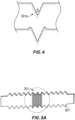
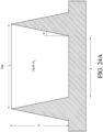
- the microstructured surface can comprise generally inverse-trapezoid-shaped structures, each including a first ridge and a second ridge having similar dimensions that project from the surface and defining a first channel therebetween.
- the height of the first and second ridge can be in the range of about 30 and about 200 ⁇ m.
- the generally inverse-trapezoid-shaped structures can comprise a second channel within the within the first channel and adjacent the first ridge and a third channel within the first channel and adjacent the second ridge, the second and third channels having similar dimensions and being recessed from the first channel.
- the depth of the second and third channel can be in the range of about 5 and about 10 ⁇ m.
- the height of the first channel can be in the range of about 2 and about 5 times taller than the depth of the second and third channels.
- the height of the first channel can be in the range of about 2 and about 3 times taller than the depth of the second and third channels.
- the height of the first channel can be in the range of about 3 and about 5 times taller than the depth of the second and third channels.
- the height of the first channel can be in the range of about 3 and about 5 times taller than the depth of the second and third channels.
- the height of the first channel can be in the range of about 3 and about 5 times taller than the depth of the second and third channels.
- the critical contact angle ⁇ for the generally inverse-trapezoid-shaped structures can satisfy the equation: ⁇ ⁇ arccos ⁇ cos ⁇ + 2 sin ⁇ ⁇ cos ⁇ + 2 where ⁇ is the ratio of the cross-sectional width of the base of the first channel to the cross-sectional height of the ridges, measured from the base of the first channel, and ⁇ is the angle between the vertical axis and a side of the first or second ridge.
- the microchannels can be generally square-shaped.
- the critical contact angle ⁇ for the microchannels can satisfy the equation: ⁇ ⁇ arccos 0.5 0.5 + X where X represents the height-to-width aspect ratio for the square shaped channels.
- the microchannels can be generally v-shaped.
- the critical contact angle ⁇ of the microchannels can satisfy the equation: ⁇ ⁇ arccos sin ⁇ 2 where ⁇ represents the angle of the v-shape.
- the microstructured surface can comprise micropillars.
- the micropillars can have substantially the same cross sectional dimensions. At least some of the micropillars can have different cross sectional dimensions from other micropillars.
- the microstructured surface can comprise inverted trapezoids bounded by microridges.
- the foregoing component can be incorporated in a mask.
- the mask can further comprise a drain in communication with the second region.
- the foregoing component can be incorporated in a conduit.
- the component can form at least a portion of an inner wall of the conduit.
- the component can be an insert in an inner lumen of the conduit.
- a wall of the conduit can be configured to communicate with a heat source.
- a component for use in a medical circuit comprises a reservoir portion configured to hold a liquid; an evaporator portion adjacent the reservoir portion configured to facilitate evaporation of the liquid; and a microstructured surface configured to transport liquid from the reservoir portion to the evaporator portion.
- the foregoing component has one, some, or all of the following properties, as well as properties described elsewhere in this disclosure.
- the evaporator portion can be heatable.
- the microstructured surface can comprise microchannels having an aspect ratio that is lower near the reservoir portion and higher near the evaporator portion the aspect ratio increases along a gradient.
- the microstructured surface can comprise first microchannels extending generally horizontally near the reservoir portion and second microchannels extending generally vertically near the evaporator portion, wherein the first microchannels are configured to transport liquid to the second microchannels.
- the foregoing component can be incorporated in a mask.
- the foregoing component can be incorporated in a humidification chamber suitable for use with a humidifier.
- the component can form at least a portion of an inner wall of the humidification chamber.
- the humidification chamber can comprise walls configured to be heated by a heater base of the humidifier.
- the humidification chamber can comprise walls configured to be heated by a heating member distinct from the humidifier.
- the humidification chamber can further comprise insulation disposed at least on or over a wall of the humidification chamber near the evaporator portion.
- the humidification chamber can further comprise at least one internal guide wall configured to guide a flow of gases within the humidification chamber.
- the at least one internal guide wall comprises a plurality of guide walls.
- the plurality of guide walls can be arranged concentrically.
- a flow channel can be defined between adjacent ones of the plurality of guide walls.
- the plurality of guide walls can define multiple flow channels, wherein at least some of the flow channels vary in size relative to one another.
- the guide wall or guide walls can be generally U-shaped and extend between an inlet port and an outlet port of the humidification chamber.
- the microstructured surface can form at least a portion of the guide wall or guide walls.
- the humidification chamber can further comprise a mixing element within the humidification chamber that facilitates mixing of gaseous and liquid phases of the water.
- the mixing element can be movable in response to a flow of gas through the humidification chamber.
- the mixing element can be a turbine comprising a plurality of blades.
- the component can comprise at least one of the plurality of blades.
- the humidification chamber can further comprise a dual valve arrangement that controls the entry of water into the humidification chamber through a water inlet, wherein at least one of the valves is not controlled by a float.
- a first valve can be controlled by a float and a second valve can be controlled by an actuator arrangement comprising a water level sensor and a valve actuator. The second valve can be normally biased to a closed position and can be moved to an open position by the valve actuator.
- the humidification chamber can comprise a planar wall and the water level sensor can be located on the planar wall.
- the inlet port and the outlet port can be located adjacent the planar wall.
- the foregoing component can be incorporated in a conduit.
- the microstructured surface can form at least a portion of an inner wall of the conduit.
- the microstuctured surface can be disposed on an insert in an inner lumen of the conduit.
- a wall of the conduit is configured to communicate with a heat source.
- a medical circuit component for use with humidified gas comprises: a wall defining a space within and wherein at least a part of the wall comprises a surface including a plurality of microchannels in and on a substrate having an outward surface with an equilibrium contact angle less than about ⁇ /2 radians, the microchannels being configured, in use, to wick liquid from a first region holding liquid water to a second region exposed to an air flow to or from a patient, and the microchannels comprising first microchannels having side portions and a bottom portion lower than the outer surface of the substrate and second microchannels having side portions higher than the outer surface of the substrate, wherein the side portions of the second microchannels are formed by ridges around or between the first microchannels.
- the foregoing medical circuit has one, some, or all of the following properties, as well as properties described elsewhere in this disclosure.
- the microstructures can be generally inverse-trapezoid-shaped structures, each including a first ridge and a second ridge having similar dimensions that project from the surface and defining a first channel therebetween.
- the height of the first ridge and the second ridge can be in the range of about 30 and about 40 ⁇ m.
- the generally inverse-trapezoid-shaped structures can comprise a second channel within the within the first channel and adjacent the first ridge and a third channel within the first channel and adjacent the second ridge, the second and third channels having similar dimensions and being recessed from the first channel.
- the depth of the second and third channel can be in the range of about 5 and about 10 ⁇ m.
- the height of the first channel can be in the range of about 2 and about 5 times taller than the depth of the second and third channels.
- the height of the first channel can be in the range of about 2 and about 3 times taller than the depth of the second and third channels.
- the height of the first channel can be in the range of about 3 and about 5 times taller than the depth of the second and third channels.
- the height of the first channel can be in the range of about 3 and about 5 times taller than the depth of the second and third channels.
- the critical contact angle ⁇ for the generally inverse-trapezoid-shaped structures can satisfy the equation: ⁇ ⁇ arccos ⁇ cos ⁇ + 2 sin ⁇ ⁇ cos ⁇ + 2 where ⁇ is the ratio of the cross-sectional width of the base of the first channel to the cross-sectional height of the ridges, measured from the base of the first channel, and ⁇ is the angle between the vertical axis and a side of the first or second ridge.
- the first microchannels can be generally square-shaped.
- the critical contact angle ⁇ for the first microchannels can satisfy the equation: ⁇ ⁇ arccos 0.5 0.5 + X where X represents the height-to-width aspect ratio for the square shaped channels.
- the first microchannels can be generally v-shaped.
- the critical contact angle ⁇ of the first microchannels can satisfy the equation: ⁇ ⁇ arccos sin ⁇ 2 where ⁇ represents the angle of the v-shape.
- a component for use in a medical circuit comprises a generally horizontal, planar microstructured surface configured to disperse a liquid placed thereon.
- the microstructured surface can be placed in a path of a flowing gas and a liquid dispenser can be configured to dispense the liquid onto the microstructured surface.
- the microstructured surface comprises surface irregularities.
- the surface irregularities comprise at least one of the group consisting of granules, ridges, grooves, channels, and particles.
- the liquid dispenser comprises at least one dropper configured to dispense the liquid one drop at a time on the microstructured surface.
- the liquid dispenser comprises a substantially flat plate positioned a distance above the microstructured surface, the plate including a plurality of holes through which the liquid is able to fall onto the microstructured surface below.
- a component for use in a medical circuit comprises a generally horizontal, planar microstructured surface configured to disperse a liquid placed thereon, wherein the microstructured surface is placed in a path of a flowing gas; and a liquid dispenser configured to dispense the liquid onto the microstructured surface.
- the foregoing component has one, some, or all of the following properties, as well as properties described elsewhere in this disclosure.
- the microstructured surface can comprise surface irregularities.
- the surface irregularities can comprise at least one of the group consisting of granules, ridges, grooves, channels, and particles.
- the liquid dispenser can comprise at least one dropper configured to dispense the liquid one drop at a time on the microstructured surface.
- the liquid dispenser can comprise a substantially flat plate positioned a distance above the microstructured surface, the plate including a plurality of holes through which the liquid is able to fall onto the microstructured surface below.
- a humidification chamber suitable for use with a humidifier comprises an exterior wall defining an interior space and at least one internal guide wall within the interior space and configured to guide a flow of gases within the humidification chamber.
- the humidification chamber can further comprises a mixing element within the humidification chamber that facilitates mixing of gaseous and liquid phases of the water.
- a humidification chamber suitable for use with a humidifier comprises an exterior wall defining an interior space; and a mixing element within the humidification chamber that facilitates mixing of gaseous and liquid phases of the water.
- the foregoing humidification chamber has one, some, or all of the following properties, as well as properties described elsewhere in this disclosure.
- the mixing element can be movable in response to a flow of gas through the humidification chamber.
- the mixing element can be a turbine comprising a plurality of blades.
- the humidification chamber can further comprise a dual valve arrangement that controls the entry of water into the humidification chamber through a water inlet, wherein at least one of the valves is not controlled by a float.
- a first valve can be controlled by a float and a second valve can be controlled by an actuator arrangement comprising a water level sensor and a valve actuator. The second valve can be normally biased to a closed position and can be moved to an open position by the valve actuator.
- the humidification chamber can comprises a planar wall and the water level sensor can be located on the planar wall.
- the inlet port and the outlet port can be located adjacent the planar wall.
- Medical circuit is a broad term and is to be given its ordinary and customary meaning to a person of ordinary skill in the art (that is, it is not to be limited to a special or customized meaning).
- a medical circuit is meant to include open circuits, such as certain CPAP systems, which can comprise a single inspiratory breathing tube between a ventilator/blower and a patient interface, as well as closed circuits.
- the outlet 113 is a Y-piece adapter.
- An expiratory tube 117 also connects to the outlet 113.
- An expiratory tube is a tube that is configured to move exhaled humidified gases away from a patient.
- the expiratory tube 117 returns exhaled humidified gases from the patient interface 115 to the ventilator/blower 105.
- the inspiratory tube 103 and/or expiratory tube 117 according to at least one configuration can comprise microstructures. These tubes (and others) are described in greater detail below.
- the humidifier 107 comprises a humidification chamber 129 containing a volume of water 130 or other suitable humidifying liquid.
- the humidification chamber 129 is removable from the humidifier 107 after use. Removability allows the humidification chamber 129 to be more readily sterilized or disposed.
- the humidification chamber 129 portion of the humidifier 107 can be a unitary construction.
- the body of the humidification chamber 129 can be formed from a non-conductive glass or plastics material.
- the humidification chamber 129 can also include conductive components.
- the humidification chamber 129 can include a highly heat-conductive base (for example, an aluminum base) contacting or associated with a heater plate 131 on the humidifier 107.
- the humidifier 107 may be a standalone humidifier, such as any of the humidifiers in the respiratory humidification range of Fisher & Paykel Healthcare Limited of Auckland, New Zealand.
- An example humidification chamber 129 is described in U.S. Patent No. 5,445,143 to Sims , which is incorporated by reference in its entirety.
- the humidifier 107 can also include electronic controls.
- the humidifier 107 includes the electronic master controller 125.
- the electronic master controller 125 is a microprocessor-based controller executing computer software commands stored in associated memory.
- the electronic master controller 125 determines when (or to what level) to energize the heater plate 131 to heat the water 130 within the humidification chamber 129.
- a heating filament (not shown) associated with the temperature probe can be used to adjust the temperature of the patient interface 115 and/or inspiratory tube 103 to raise the temperature of the inspiratory tube 103 and/or patient interface 115 above the saturation temperature, thereby reducing the opportunity for unwanted condensation.
- the patient interface 115 can comprise microstructures and is described in greater detail below.
- exhaled humidified gases are returned from the patient interface 115 to the ventilator/blower 105 via the expiratory tube 117.
- the expiratory tube 117 can have a temperature probe and/or heating filament, as described above with respect to the inspiratory tube 103, integrated with it to reduce the opportunity for condensation. Furthermore, the expiratory tube 117 need not return exhaled gases to the ventilator/blower 105.
- exhaled humidified gases can be passed directly to ambient surroundings or to other ancillary equipment, such as an air scrubber/filter (not shown). In certain embodiments, the expiratory tube is omitted altogether.
- the inspiratory tube 103, expiratory tube 117, humidification chamber 129, and/or patient interface 115 of the example medical circuit can comprise microstructures.
- a discussion of these components follows. The invention is not limited by these embodiments, however, and it is contemplated that the disclosed microstructures can be integrated into a variety of medical components that contact and/or transport humidified gases, such as humidified air.
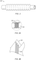
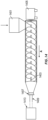
- FIG. 2 shows a perspective view of a tube 201 suitable for use in a medical circuit, according to at least one embodiment.
- the tube 201 can be corrugated, which advantageously improves the tube's flexibility.
- the tube 201 can have a relatively smooth, non-corrugated wall in certain embodiments.
- the tube 201 can be used for transporting gases to and/or from infant or neonatal patients. In certain embodiments, the tube 201 can be used for transporting gases to and/or from standard patients, such as older children and adults.
- standard patients such as older children and adults.
- the tube 201 is formed from an extrudate comprising one or more polymers.
- the polymer is selected so that the resulting tube 201 is generally flexible.
- Preferred polymers include Linear Low Density Polyethylene (LLDPE), Low Density Polyethylene (LDPE), Polypropylene (PP), Polyolefin Plastomer (POP), Ethylene Vinyl Acetate (EVA), Plasticized Polyvinylchloride (PVC), or a blend of two or more of these materials.
- the polymer(s) forms at least 98.4 (or about 98.4), 98.5 (or about 98.5), 98.6 (or about 98.6), 98.7 (or about 98.7), 98.8 (or about 98.8), 98.9 (or about 98.9), 99.0 (or about 99.0), 99.1 (or about 99.1), 99.2 (or about 99.2), 99.3 (or about 99.), 99.4 (or about 99.4), 99.5 (or about 99.5), 99.6 (or about 99.6), 99.7 (or about 99.7), 99.8 (or about 99.8), or 99.9 (or about 99.9) weight percent (wt. %) of the total extrudate.
- the extrudate comprises 99.488 (or about 99.488) wt. % or about 99.49 (or about 99.49) wt. % LLDPE.
- the tube 201 is formed from a foamed polymer as described in commonly assigned International Publication No. WO 2001/077250 A1 , which is incorporated by reference in its entirety.
- microstructures may be formed of soft metal materials, such as aluminum foil, brass, and copper.
- the materials selected can have a high surface energy.
- the substrate materials can be coated and can include an additive that increases the surface energy of the substrate material.
- the use of the metal alone without being formed into microstructures may be advantageous simply because of the high surface energy.
- microstructures may be formed of the metals, for example, by first forming the soft metal into a film or a thin film and subsequently stamping the material to form microstructures. The stamped material may then be used to form any number of suitable components in the humidification devices of the present disclosure.
- At least an interior portion of the tube 201 may formed of a metal that may or may not have been stamped to form microstructures.
- a stamped metallic film may form a surface on any number of structures (walls, towers, fins, base, etc.) within a humidification chamber.
- the tube 201 can comprise one or more conductive filaments.
- the tube 201 can comprise two or four conductive filaments, and pairs of the conductive filaments can be formed into a connecting loop at one or both ends of the tube 201.
- the one or more filaments can be disposed on the outside of the tube 201, for example, spirally wound around the outside of the tube 201, or disposed on the inner wall of the tube 201, for example, spirally wound around along the lumen wall. Filaments are discussed in greater detail below.
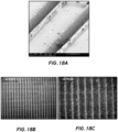
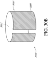
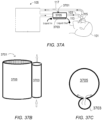
- the inner walls of the tube 201 comprise microstructures 301, as shown in FIG. 3A (not to scale). A first magnified view of a portion of the microstructures 301 is shown in FIG. 3B.
- FIG. 3A A first magnified view of a portion of the microstructures 301 is shown in FIG. 3B.
- FIG. 3B shows the microstructures 301 at a greater magnification than FIG. 3A .
- the microstructures 301 are axially disposed along the tube 201 (that is, the microstructures extend in a direction perpendicular to longitudinal length of the tube 201).
- Polymers generally have a low surface energy, resulting in poor wettability.
- Surfactants such as cationic surfactants, can be particularly desirable additive materials.
- Suitable surface modifying agents include glycerol monostearate (GMS), ethoxylated amine, alkanesulphonate sodium salt, and lauric diethanolamide and additives comprising these substances.
- MLDNA-418 supplied by Clariant (New Zealand) Ltd.
- the surface modifying agent comprises at least about 0.05 (or about 0.05), 0.1 (or about 0.1), 0.15 (or about 0.15), 0.2 (or about 0.2), 0.25 (or about 0.25), 0.3 (or about 0.3), 0.35 (or about 0.35), 0.4 (or about 0.4), 0.45 (or about 0.45), 0.5 (or about 0.5), 1.1 (or about 1.1), 1.2 (or about 1.2), 1.3 (or about 1.3), 1.4 (or about 1.4), or 1.5 (or about 1.5) wt.
- the tube extrudate comprises 0.25 wt. % (or about 0.25 wt. %) of surface modifying agent.
- the tube extrudate comprises 0.5 wt. % (or about 0.5 wt. %) of surface modifying agent.
- Suitable hydrophilizing agents can be any agent or agents generally capable of increasing the hydrophilic character of a composition.
- the surfactant or hydrophilizing agent can comprise an ethoxylized fatty alcohol, such as those described in EP 0 480 238 B1 , the entirety of which is incorporated by reference herein.
- the surfactant or hydrophilizing agent can comprise a non-ionic surface-active substance, such as the nonylphenolethoxylates, polyethylene glycol-monoesters and diesters, sorbitan esters, polyethylene glycol-monoethers and diethers and others described in EP 0 268 347 B1 , or a non-ionic perfluoralkylated surface-active substance, such as those described in WO 87/03001 , the entireties of which are incorporated by reference herein.
- the surfactant or hydrophilizing agent can contain silicon moieties.
- the surfactant or hydrophilizing agent can comprise a wetting agent, such as hydrophilic silicon oils as described in the above-mentioned WO 87/03001 and EP 0 231 420 B1 , the entirety of which is incorporated by reference herein.
- the surfactant or hydrophilizing agent can comprise polyether carbosilanes, such as those described in WO 2007/001869 , particularly at pages 13 and 14, the entirety of which is incorporated by reference herein.
- Other such suitable agents are described in US 5,750,589 , US 4,657,959 and EP 0 231 420 B1 , as referenced in WO 2007/001869 , the entireties of which are incorporated by reference herein.
- the surfactant or hydrophilizing agent can comprise ethoxylated surfactants containing a siloxane solubilizing group, such as those described in the above-mentioned US 4,657,949 and WO2007/001869 .
- ethoxylated surfactants are the SILWET ® line of surface active copolymers (e.g., SILWET ® L-77) available from Momentive Performance Materials, Inc. of Albany, New York USA and the MASIL ® SF19 available from Emerald Performance Materials, LLC of Cuyahoga Falls, Ohio USA.
- one or more hydrophilizing agents are applied to a microstructured surface after the microstructures are formed.
- the microstructured surface can be dipped in, sprayed with, or otherwise applied with a suspension of ELVAMIDE ® nylon multipolymer resin (E. I. du Pont de Nemours & Co., Wilmington, DE) in a volatile solvent, such as methanol or ethanol.
- a volatile solvent such as methanol or ethanol.
- the volatile solvent is then allowed to evaporate.
- a thin (in the range of 1 ⁇ m and 10 ⁇ m or in the range of about 1 ⁇ m and about 10 ⁇ m) layer of ELVAMIDE ® resin coats the microstructures, improving the surface hydrophilicity.
- Suitable methods include physical, chemical, and radiation methods.
- Physical methods include, for example, physical adsorption and Langmuir-Blodgett films.
- Chemical methods include oxidation by strong acids, ozone treatment, chemisorption, and flame treatment.
- Radiation methods include plasma (glow discharge), corona discharge, photo-activation (UV), laser, ion beam, electron beam, and gamma irradiation.
- a suitable surface modification method or agent it is possible to provide a tube wall having surface property contact angles of less than 50 (or about 50), 45 (or about 45), 40 (or about 40), 35 (or about 35), 30 (or about 30), 25 (or about 25), 20 (or about 20) degrees (°), as measurable by an angle measurement device such as a goniometer.
- tube walls having surface property contact angles of less than 35° (or about 35°) provide useful results.
- the contact angle is less than ⁇ /2 (or about ⁇ /2). More desirably, the contact angle is 0° or about 0°.
- the sample with 5% MLDNA-418 surface modifying agent produced the lowest measured contact angle compared to other surface modification methods tested.
- the additive material is added to the bulk polymer extrudate. It can be desirable to add the material in the polymer matrix so that the additive material replenishes the surface for the useful life of the tube.
- the material can be added as a surface treatment on the polymer, for example, by coating a surface of the polymer with the material.
- a microstructured surface can be brushed, sprayed, or otherwise coated with additive material such as HYDRON anti-fog coating (MXI, Industries, Lancaster, Pennsylvania), EXXENE anti-fog coatings such as HCAF-100 (Exxene Corporation, Corpus Christi, Texas), and MAKROLON anti-fog (Bayer Corporation) to produce a thin (e.g., 1 ⁇ m or thereabout) coating of additive material.
- additive material such as HYDRON anti-fog coating (MXI, Industries, Lancaster, Pennsylvania), EXXENE anti-fog coatings such as HCAF-100 (Exxene Corporation, Corpus Christi, Texas), and MAKROLON anti-fog (Bayer Corporation) to produce a thin (e.g., 1 ⁇ m or thereabout) coating of additive material.
- a surface coating can be desirable because of low costs and ease of manufacture.
- a thin film of hydrophilic material such as breathable polyurethanes, for example, ESTANE 58245 (Lubrizol Corporation, Wickliffe, Ohio), breathable polyesters, for example, ARNITEL VT3108 (DSM Engineering Plastics, Sittard, Netherlands), or breathable polyamides, for example PEBAX (Arkema, Colombes, France) can be cast as a surface modifying agent.
- breathable polyurethanes for example, ESTANE 58245 (Lubrizol Corporation, Wickliffe, Ohio), breathable polyesters, for example, ARNITEL VT3108 (DSM Engineering Plastics, Sittard, Netherlands), or breathable polyamides, for example PEBAX (Arkema, Colombes, France)
- PEBAX Arkema, Colombes, France
- ESTANE 58245 pellets can be dissolved in a tetrahydrofuran (THF) of dimethylformamide (DMF) solvent and cast onto microstructures machined from brass or aluminum using a micromilling process.
- Typical dimensions for the thin film are in the range of 1 to 10 ⁇ m (or about 1 to 10 ⁇ m).
- the solvent, breathable material, and microstructure material combination is selected such that the microstructure shape and quality is not substantially influenced, for example, by dissolving the microstructures with the solvent.
- a tube e.g., the inspiratory tube 103 or expiratory tube 117
- a tube generally extends in a horizontal direction, although certain portions can extend vertically, particularly near the ends of the tube, and some portions can be sloped.
- condensate tends to run down the vertical and sloped portions of the tube and pool at the lowest points of the generally horizontal tube.
- microstructures When microstructures are perpendicular to the generally horizontal tube bottom, the microstructures will move pooled condensate vertically, against gravity.
- This action increases the amount of condensate on the tube walls and, thus, the surface area of condensate exposed to the air stream. Exposing a greater surface area of condensate to the air stream increases the likelihood that the condensate will evaporate into the air stream. Therefore, the perpendicular configuration reduces the condensate pooled in the tube and improves the likelihood that the air flowing through the tube maintains a desired level of humidity near saturation.
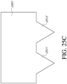
- a curable material 2609 is applied between the second impression material 2605 and a target surface 2607.
- the target surface 2607 include plastics, such as acrylonitrile butadiene styrene or polycarbonate or metals such as aluminum.
- the curable material 2609 can be applied to a plastic humidification chamber target surface 2607, and the second impression material 2605 can be overlaid on the curable material 2609.
- the surface of the target surface 2607 can be roughened, e.g., by sanding, prior to application of the second impression material 2605 to improve adhesion.
- Suitable materials for the curable material 2609 include UV curable acrylic and heat curable epoxy or heat curable acrylic.
- either or both of the primary valve system 3112 and the secondary valve system 3114 can be controlled by a float or by an alternative arrangement, such as a sensor-based actuator, for example.
- Float controlled valves are often normally open and are closed as a result of a rise in water level within the humidification chamber 3102.
- Sensors and valve actuators can be normally open or normally closed and can be moved to the other position by the actuator.
- An advantage of replacing float valves with a sensor and actuator valve is to avoid covering water surface area with a float to increase the surface area available to produce water vapor.
- a desirable orientation of the secondary push tube 3146 can be maintained throughout a range of pivotal movement of the base 3142.
- the retainer cap 3144 can be secured to the base 3142 by any suitable arrangement, such as a snap-fit arrangement, mechanical fasteners, adhesives or ultrasonic welding, for example and without limitation.
- a space is provided between the retainer cap 3144 and the secondary push tube 3146 such that the retainer cap 3144 inhibits separation of the secondary push tube 3146 from the base 3142, while allowing for relatively free movement of the secondary push tube 3146 relative to the base 3142.
- biasing arrangements could also be used, including biasing elements that are separate from the base 3142, retainer cap 3144 or other illustrated components of the valve body assembly 3134.
- the spring arms 3152 are configured to provide a biasing force tending to bias the valve body assembly 3134 toward the closed position.
- the humidifier 107 includes a mechanism for moving the valve body assembly 3134 into an open position against the biasing force of the spring arms 3152.
- the valve body assembly 3134 preferably is moved to the open position during normal operation of the humidifier 107, such as when the humidification chamber 3102 is positioned onto a base of the humidifier 107.
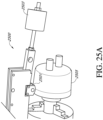
- the humidifier 107 includes an actuator arrangement 3154 including an actuator body, such as an actuator rod 3156, that selectively moves the valve body assembly 3134 to the open position.
- the actuator rod 3156 preferably is operated by a control system of the humidifier 107 (e.g., the electronic master controller 125) to move the valve body assembly 3134 into the open position during normal operation of the humidifier 107.
- the sensor 3162 can provide a suitable signal (including the absence of a signal) to the control system of the humidifier 107, which can move the actuator rod 3156 (or other actuator arrangement 3154) to permit the valve body assembly 3134 to move to the closed position. If the actual water level is at or below the desired level, the sensor 3162 can provide a suitable signal (including the absence of a signal) to the control system of the humidifier 107, which can move the actuator rod 3156 (or other actuator arrangement 3154) to move the valve body assembly 3134 to the open position.
- the control system of the humidifier 107 moves the valve body assembly 3134 to the open position only if the humidifier 107 is provided with power or turned on, if the sensor 3162 is functional and if the water level is at or below the desired level.
- Suitable optical sensors can include, for example, LED or LDR sensors, or other sensor types that can detect the presence or absence of water within the humidification chamber 3102.
- the sensor 3162 can be or include a camera with a digital image processing, which can be incorporated in the control system of the humidifier 107, configured to detect the water level or determine a presence or absence of water at a particular level.
- the water inlet 3108 incorporates the dual valve arrangement 3110 which includes the first valve seat 3132 and the second valve seat 3138.
- the illustrated valve actuating mechanism includes the push rod 3124, which is situated within the co-axial outer cylindrical secondary push tube 3146.
- the push rod 3124 and secondary push tube 3146 are capable of moving freely and independently of one another.
- the end of the push rod 3124 facing the water inlet 3108 is tapered to a blunt point, which forms the valve body 3130.
- the valve body 3130 of the push rod 3124 and the valve body element 3136 of the secondary push tube 3146 are covered by a valve seal element 3164, which can be a flexible sealing membrane.
- valve seal element 3164 is configured to fit snugly over the rim of the secondary push tube 3146, thus coupling the secondary push tube 3146 to the push rod 3124 in a floating connection.
- the valve seal element 3164 directly contacts the first valve seat 3132 and the second valve seat 3138 when the respective valve is in a closed position.
- the valve seal element 3164 can prevent water from entering the humidification chamber 3102 through the water inlet 3108 when the secondary valve system 3114 is closed regardless of the position of the primary valve system 3112.
- the valve seal element 3164 can be made of material that is supple but strong, for example, a medical grade silicone rubber material.
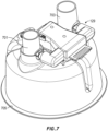
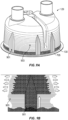
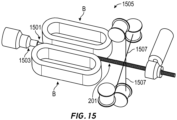
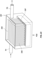
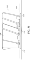
- the humidification chamber 3102 includes gas flow guiding features and/or surface area-enhancing features, such as one or more guide walls 3180 that can guide or direct a portion of the flow of gas within the humidification chamber 3102 between the inlet port 3170 and the outlet port 3172.
- the humidification chamber 3102 comprises a plurality of guide walls 3180 spaced from one another to define one or more flow channels 3182.
- the guide walls 3180 can include internal guide walls and, in some configurations, the outer side walls of the humidification chamber body 3104 can form guide walls.
- the guide walls 3180 are generally concentrically-arranged.
- the guide walls 3180 and/or flow channels 3182 can have varying heights/depths.
- adjacent flow channels 3182 have different depths in an alternating fashion; with the shallow channels 3182 having about one-half the depth of the deep channels 3182.
- the widths of the flow channels 3182 can be generally the same or different depending on the desired flow characteristics.
- the flow channels 3182 extend a substantial height of the interior space of the humidification chamber 3102 and can, but do not necessarily, contact the heat transfer base 3106 or other bottom surface of the humidification chamber 3102.
- the guide walls 3180 and flow channels 3182 are generally U-shaped when viewing the top of the humidification chamber 3102.
- the inlet port 3170 and the outlet port 3172 are located near respective ends of the U-shaped flow channels 3182.
- the guide walls 3180 and flow channels 3182 extend along a substantial portion or a substantial entirety of a flow path between the inlet port 3170 and the outlet port 3172.
- the illustrated flow channels 3182 are configured to provide for parallel flow through the channels 3182. That is, a flow of gases entering the humidification chamber 3102 is divided amongst the available flow channels 3182.
- the flow channels 3182 could be arranged in series such that a flow of gases through the humidification chamber 3102 passes through multiple or all of the available flow channels 3182 in serial fashion to increase residence time within the humidification chamber 3102.
- the guide walls 3180 can be configured to define a tortuous flow path through the humidification chamber 3102.
- the guide walls 3180 provide additional surface area for the placement of any of the microstructures described herein to increase the total surface area of water available to the flow of gas through the humidification chamber 3102.
- one or more walls of the humidification chamber 3102 e.g., internal guide walls 3180 and/or external walls
- the humidification chamber 3102 can comprise walls configured to be heated by a heating member distinct from the humidifier 107.
- the humidification chamber 3102 can further comprise insulation disposed at least on or over a wall of the humidification chamber 3102 near the evaporator portion.
- the walls 3180 can be provided primarily or entirely to increase the surface area for microstructures and provide little or no guiding of the gas flow.
- the inlet port 3170 and the outlet port 3172 can be located on opposite sides of the dual valve arrangement 3110.
- the guide walls 3180 facilitate desired flow of the gases through the humidification chamber 3102 between the inlet port 3170 and the outlet port 3172 such that the inlet port 3170 and the outlet port 3172 can be positioned relative to the overall humidification chamber 3102 as desired, such as at or near a wall of the humidification chamber body 3104.
- the inlet port 3170 and/or the outlet port 3172 can be positioned at or near, for example, a rear wall 3184 of the humidification chamber body 3104.
- the rear wall 3184 is generally planar, which can facilitate, make practical or make possible the use of the optical (or other) sensor 3162.
- guide walls 3180 can make possible or practical the use of shapes for the humidification chamber body 3104 other than generally cylindrical, which can increase the available surface area of the water within the humidification chamber 3102 and/or can increase the surface area of the heat transfer base 3106 for more efficient heating of the water within the humidification chamber 3102.
- the humidification chamber 3102 can include other structures that increase surface area available for microstructures and/or facilitate mixing of the gas and liquid phases of the water within the humidification chamber 3102.
- elimination of the secondary float provides room within the humidification chamber 3102 for a mixing element or structure 3186 that facilitates mixing of the gas and liquid phases of the water within the humidification chamber 3102.
- the mixing element 3186 is a turbine that is rotatable within and relative to the humidification chamber 3102.
- the turbine or other mixing structure 3186 could form a portion of or otherwise be integrated with a secondary float and/or could be stationary instead of movable.
- valve actuation arrangements for the dual valve arrangement 3110 can be used, including float controlled valves and sensor/actuator controlled valves, for example and without limitation.
- Stationary mixing structures 3186 could be supported on a bottom surface of the humidification chamber 3102 or could be supported or made integral with the humidification chamber body 3104, such as extending downwardly from an upper wall of the humidification chamber body 3104, for example.
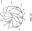
- the turbine 3186 comprises a plurality of blades 3188 secured to a base 3190.
- the blades 3188 are separate from the base 3190 and held in place by a plurality of tabs 3192, which may provide a snap-fit arrangement with the blades 3188.
- Other suitable methods or mechanisms for securing the blades 3188 to the base 3190 can also be used, including forming the blades 3188 and base 3190 together as a unitary structure.
- the blades 3188 can be arranged radially on the base 3190 or can be offset from a radial alignment, as illustrated. In some configurations, the blades 3188 can be tilted or otherwise angled relative to an axis of rotation of the turbine 3186 in a vertical direction.
- the illustrated blades 3188 are generally or substantially planar, which can be advantageous in permitting the formation of microstructures, as described herein. However, in other configurations, the blades 3188 can be curved in a width and/or length direction.
- the turbine 3186 can be rotatable in response to a flow of gas through the humidification chamber 3102.
- other types of movable mixing elements 3186 can be movable in response to a flow of gas through the humidification chamber 3102.
- the turbine 3186 is positioned within a flow path of gases moving through the humidification chamber 3102.
- guide walls 3180 or other guide structures can also be provided to facilitate the flow of gas into or out of the turbine 3186.
- the turbine 3186 can facilitate mixing of gaseous and liquid phases of water, which allows more moisture and heat to be extracted from the humidification chamber 3102 due to the more homogenous temperature mix. It is contemplated that even a low rotational speed of the turbine 3186 or other mixing element will result in advantageous mixing of the liquid and gas phases.
- the inlet port 3170 and the outlet port 3172 can be positioned to facilitate or direct a desired flow path of gases moving through the humidification chamber 3102.
- the inlet port 3170 and the outlet port 3172 can be positioned on opposing sides of the water inlet 3108 and the dual valve arrangement 3110 at or near a planar wall 3184 of the humidification chamber 3102.
- the inlet port 3170 and the outlet port 3172 can be oriented in a vertical direction or other direction, as desired.
- the inlet port 3170 and the outlet port 3172 can be generally or substantially tangential with respect to the turbine 3186.
- the inlet port 3170 and the outlet port 3172 can be generally or substantially radially oriented with respect to the turbine 3186, as illustrated in broken lines.
- the inlet port 3170 can be positioned generally along the axis of rotation of the turbine 3186, such as positioned above the turbine 3186.
- the flow of gas enters the central portion of the turbine 3186 and flows outwardly between the blades 3188 to the outlet port 3172.
- the flow of gas can be directed to a particular location (e.g., center) of the mixing element 3186 and dispersed as desired (e.g., outwardly) by the mixing element 3186.
- the turbine 3186 is supported for rotation relative to the humidification chamber 3102 in a manner to minimize resistance to rotation.
- the turbine 3186 can be configured to float on the water within the humidification chamber 3102 at least slightly above the bottom surface of the humidification chamber 3102 (e.g., the heat transfer base 3106).
- the bottom surface of the turbine 3186 can be provided with a projection 3194 (e.g., a pointed or conical projection) to reduce or minimize friction in the event that the turbine 3186 contacts a surface of the humidification chamber 3102.
- the turbine 3186 could be configured such that the projection 3194 intentionally contacts or rests upon a surface of the humidification chamber 3102.
- a desirable water level within the humidification chamber 3102 is above the base 3190 of the turbine 3186 such that liquid water is in contact with the lower portions of the blades 3188 to facilitate wicking of the water vertically on the blades 3188 via the microstructures, as described herein.
- the desirable or normal water level 3196 can be slightly above the upper surface of the base 3190, such as at or below the tabs 3192, for example and without limitation.
- the desirable or normal water level 3196 is selected to be sufficiently high to facilitate or achieve a desirable amount of wicking of the water up the blades 3188 without unduly impeding rotation of the turbine 3186.
- certain embodiments include the realization that microstructures can be incorporated into patient interfaces, including, without limitation, masks (such as tracheal mask, face masks and nasal masks), cannulas, and nasal pillows.
- masks such as tracheal mask, face masks and nasal masks
- cannulas cannulas
- nasal pillows cannulas
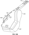
- FIG. 10A shows a front perspective view of an example of the patient interface 115.
- the patient interface 115 can be used in the field of respiratory therapy.
- the patient interface 115 has particular utility with forms of positive pressure respiratory therapy.
- the patient interface 115 can be used for administering continuous positive airway pressure (“CPAP") treatments.
- CPAP continuous positive airway pressure
- VPAP variable positive airway pressure
- BiPAP bi-level positive airway pressure
- the patient interface 115 can be used with any suitable CPAP system.
- the patient interface 115 can comprise any suitable mask configuration. For example, certain features, aspects and advantages of the present invention can find utility with nasal masks, full face masks, oronasal masks or any other positive pressure mask.
- the illustrated interface is a full face mask 1001.
- the mask 1001 generally comprises a mask assembly 1003 and a connection port assembly 1005.
- the mask assembly 1003 generally comprises a mask seal 1007 that, in use, contacts a user's face.
- FIG. 10B illustrates a configuration of the mask 1001 of FIG. 10A incorporating one or more conductive filaments 1009.
- the conductive filaments 1009 can be arranged in a generally sinuous pattern.
- a variety of configurations are possible, such as a grid-shaped configuration, a coil, or a ring.
- the one or more conductive filaments 1009 can be attached to an outer surface of the mask 1001 wall (that is, the surface of the mask 1001 configured to face the ambient air during use).
- the one or more conductive filaments 1009 can also be attached to an inner surface of the mask 1001 wall (that is, the surface of the mask 1001 configured to face the patient during use).
- the one or more conductive filaments 1009 can also be embedded or otherwise incorporated in the mask 1001 wall.
- the last configuration can be desirable because it can prevent a patient from touching the conductive filaments 1009.
- a combination of the foregoing configurations can also be incorporated in the mask 1001.
- the mask 1001 wall itself, or at least a portion of the mask 1001 wall can be conductive.
- the mask 1001 can comprise a conductive polymer or a conductive metal.
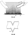
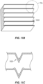
- FIG. 11A is a rear elevation view of the mask 1001 of FIG. 10 .
- FIG. 11A generally illustrates an example configuration for microstructures 1101 on the inside surface of the mask. The properties of the microstructures 1101 discussed in the preceding sections are incorporated by reference.
- the example mask 1001 has a longitudinal axis LA and a transverse axis TA.
- the mask 1001 comprises a first portion 1103 on one side of the longitudinal axis LA and a second portion 1105 on the other side of the longitude axis LA.
- the microstructures 1101 extend along the underside of the mask 1001 parallel the transverse axis TA.
- the microstructures 1101 on either side of the longitudinal axis LA form mirror image patterns.
- the microstructures 1101 are not drawn to scale and are for illustrative purposes only.
- FIG. 11B shows a first magnified view of a portion of the microstructures 1101 of FIG. 11A .
- FIG. 11C illustrates a cross section of an example one of the microstructures 1101.
- the microstructure is a microchannel.
- the microstructures can be similar to those discussed above, and the discussion of their shapes and properties is incorporated by reference here.
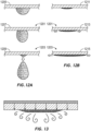
- FIG. 12A shows a schematic of water droplet formation on an interface surface that does not incorporate microstructures.
- FIG. 12B shows a schematic of water spreading on an interface surface that does incorporate microstructures.
- 1201 designates the outer surface of the interface (that is, the surface of the interface configured to face the ambient air during use)
- 1203 designates the inner surface of the interface (that is, the surface of the interface configured to face the patient during use).
- Patient interfaces experience very high humidity conditions.
- water droplets can readily form on the inner surface of a patient interface when the inner surface 1203 of the interface is smooth (or relatively smooth).
- these water droplets will run down to a lower area of the patient interface and pool together or drip onto a patient's face.
- the incorporation of microstructures on the inner surface 1203 of a patient interface can ameliorate this problem.
- the microstructures spread out the condensate along the length (or at least a portion of the length) of the microstructures, which prevents the condensate from forming droplets.
- condensate spreads out along the microstructures over a large surface area, the condensate can evaporate more readily. This spreading action also decreases the likelihood that condensate will pool in a lower area or drop on the patient's face.
- incorporation of microstructures on the inner surface 1203 allows condensate to be redirected from the patient interface onto an absorbent layer (not shown), such as a sponge or breathable membrane.
- FIG. 11D shows a rear elevation view of the mask 1001 of FIG. 10A .
- FIG. 11D schematically illustrates condensate spreading out along the microstructures 1101 on the inner surface of the mask.
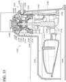
- the one or more conductive filaments 1009 ( FIG. 10B ) comprise one or more heating filaments configured to heat the mask 1001 wall.
- the heating filament can be connected to an electrical supply and thereby apply heat to the mask 1001 body. As shown in FIG. 13 , the added heat speeds evaporation of condensate spread out in or on the microstructures.
- a component for use in a medical circuit comprising: a first region that, in use, contacts liquid; a second region that is distinct from the first region; a microstructured surface in communication with the first region and the second region configured, in use, to wick liquid from the first region to the second region, wherein the microstructured surface comprises a substrate having an equilibrium contact angle less than about ⁇ /2 radians, wherein the microstructured surface comprises generally inverse-trapezoid-shaped structures, each including a first ridge and a second ridge having similar dimensions that project from the surface and defining a first channel therebetween.
- the second region, in use is exposed to higher velocity air and the first region, in use, is exposed to lower velocity air.
- the second region is configured to communicate with a heat source.
- the microstructured surface is configured to communicate with a heat source.
- the microstructured surface comprises generally parallel microchannels.
- the height of the first and second ridge is in the range of about 30 and about 200 ⁇ m.
- the generally inverse-trapezoid-shaped structures comprise a second channel within the within the first channel and adjacent the first ridge and a third channel within the first channel and adjacent the second ridge, the second and third channels having similar dimensions and being recessed from the first channel.
- the depth of the second and third channel is in the range of about 5 and about 10 ⁇ m.
- the height of the first channel is in the range of about 2 and about 5 times taller than the depth of the second and third channels.
- the height of the first channel is in the range of about 2 and about 3 times taller than the depth of the second and third channels.
- the height of the first channel is in the range of about 3 and about 5 times taller than the depth of the second and third channels.
- the component is an insert in an inner lumen of the conduit.
- a wall of the conduit is configured to communicate with a heat source.
- a humidification chamber suitable for use with a humidifier, the humidification chamber comprising: a reservoir portion configured to hold a liquid; an evaporator portion adjacent the reservoir portion configured to facilitate evaporation of the liquid; a microstructured surface configured to transport liquid from the reservoir portion to the evaporator portion; and at least one internal guide wall configured to guide a flow of gases within the humidification chamber.
- the evaporator portion is heatable.
- the microstructured surface comprises microchannels having an aspect ratio that is lower near the reservoir portion and higher near the evaporator portion the aspect ratio increases along a gradient.
- the microstructured surface comprises first microchannels extending generally horizontally near the reservoir portion and second microchannels extending generally vertically near the evaporator portion, wherein the first microchannels are configured to transport liquid to the second microchannels.
- the component forms at least a portion of an inner wall of the humidification chamber.
- the humidification chamber comprises walls configured to be heated by a heater base of the humidifier.
- the humidification chamber comprises walls configured to be heated by a heating member distinct from the humidifier.
- insulation disposed at least on or over a wall of the humidification chamber near the evaporator portion.
- the plurality of guide walls are arranged concentrically.
- a flow channel is defined between adjacent ones of the plurality of guide walls.
- the plurality of guide walls defines multiple flow channels, wherein at least some of the flow channels vary in size relative to one another.
- the guide wall or guide walls are generally U-shaped and extend between an inlet port and an outlet port of the humidification chamber.
- the microstructured surface forms at least a portion of the guide wall or guide walls.
- a mixing element within the humidification chamber that facilitates mixing of gaseous and liquid phases of the water.
- the mixing element is movable in response to a flow of gas through the humidification chamber.
- the mixing element is a turbine comprising a plurality of blades.
- the component comprises at least one of the plurality of blades.
- a dual valve arrangement that controls the entry of water into the humidification chamber through a water inlet, wherein at least one of the valves is not controlled by a float.
- a first valve is controlled by a float and a second valve is controlled by an actuator arrangement comprising a water level sensor and a valve actuator.
- the second valve is normally biased to a closed position and is moved to an open position by the valve actuator.
- the humidification chamber comprises a planar wall and the water level sensor is located on the planar wall.
- the inlet port and the outlet port are located adjacent the planar wall.
- a medical circuit component for use with humidified gas comprising: a wall defining a space within and wherein at least a part of the wall comprises a surface including a plurality of microstructures in and on a substrate having an outward surface with an equilibrium contact angle less than about ⁇ /2 radians, the microstructures being configured, in use, to wick liquid from a first region holding liquid water to a second region exposed to an air flow to or from a patient, wherein the microstructures are generally inverse-trapezoid-shaped structures, each including a first ridge and a second ridge having similar dimensions that project from the surface and defining a first channel therebetween.
- the height of the first ridge and the second ridge is in the range of about 30 and about 40 ⁇ m.
- the generally inverse-trapezoid-shaped structures comprise a second channel within the within the first channel and adjacent the first ridge and a third channel within the first channel and adjacent the second ridge, the second and third channels having similar dimensions and being recessed from the first channel.
- the height of the first channel is in the range of about 2 and about 5 times taller than the depth of the second and third channels.
- the height of the first channel is in the range of about 2 and about 3 times taller than the depth of the second and third channels.
- the height of the first channel is in the range of about 3 and about 5 times taller than the depth of the second and third channels.
- the critical contact angle ⁇ for the generally inverse-trapezoid-shaped structures satisfies the equation: ⁇ ⁇ arccos ⁇ cos ⁇ + 2 sin ⁇ ⁇ cos ⁇ + 2 where ⁇ is the ratio of the cross-sectional width of the base of the first channel to the cross-sectional height of the ridges, measured from the base of the first channel, and ⁇ is the angle between the vertical axis and a side of the first or second ridge.
- a humidification chamber suitable for use with a humidifier, comprising: an exterior wall defining an interior space; at least one internal guide wall within the interior space and configured to guide a flow of gases within the humidification chamber.
- the at least one internal guide wall comprises a plurality of guide walls.
- the plurality of guide walls are arranged concentrically.
- a flow channel is defined between adjacent ones of the plurality of guide walls.
- the plurality of guide walls defines multiple flow channels, wherein at least some of the flow channels vary in size relative to one another.
- the guide wall or guide walls are generally U-shaped and extend between an inlet port and an outlet port of the humidification chamber.
- a microstructured surface forms at least a portion of the guide wall or guide walls.
- a mixing element within the humidification chamber that facilitates mixing of gaseous and liquid phases of the water.
- the guide wall or guide walls are attached to a top wall of the humidification chamber.
- a humidification chamber suitable for use with a humidifier, comprising: an exterior wall defining an interior space; a mixing element within the humidification chamber that facilitates mixing of gaseous and liquid phases of the water.
- the mixing element is movable in response to a flow of gas through the humidification chamber.
- the mixing element is a turbine comprising a plurality of blades.
- a dual valve arrangement that controls the entry of water into the humidification chamber through a water inlet, wherein at least one of the valves is not controlled by a float.
- a first valve is controlled by a float and a second valve is controlled by an actuator arrangement comprising a water level sensor and a valve actuator.
- the second valve is normally biased to a closed position and is moved to an open position by the valve actuator.
- the humidification chamber comprises a planar wall and the water level sensor is located on the planar wall.
- the inlet port and the outlet port are located adjacent the planar wall.
- a bottom surface of the turbine comprises a projection that defines an axis of rotation.
- the turbine comprises a base and the plurality of blades are connectable to the base.
- the blades are generally or substantially planar.
- a humidification chamber suitable for use with a humidifier, comprising: an exterior wall defining an interior space; a water inlet that permits water to enter the interior space; a primary valve that controls the entry of water into the humidification chamber through the water inlet, wherein the primary valve is controlled by a float; a secondary valve that controls entry of water into the humidification chamber through the water inlet, wherein the secondary valve is not controlled by a float.
- the secondary valve is controlled by an actuator arrangement comprising a water level sensor and a valve actuator.
- the second valve is normally biased to a closed position and is moved to an open position by the valve actuator.
- the second valve comprises a valve body assembly having unitary spring arms that normally bias the valve body assembly to a closed position of the second valve.
- the humidification chamber comprises a planar wall and the water level sensor is located on the planar wall.
- the inlet port and the outlet port are located adjacent the planar wall.
- a medical circuit component for use in a medical circuit comprising: a first region that, in use, contacts liquid; a second region that is distinct from the first region; a microstructured surface in communication with the first region and the second region configured, in use, to wick liquid from the first region to the second region, wherein the microstructured surface comprises generally inverse-trapezoid-shaped structures, each including a first ridge and a second ridge having similar dimensions that project from the surface and defining a first channel therebetween.
- the microstructured surface comprises a substrate having an equilibrium contact angle less than about ⁇ /2 radians.
- the second region is a region exposed to an air flow to or from a patient.
- the second region, in use is exposed to higher velocity air and the first region, in use, is exposed to lower velocity air.
- the second region and/or the microstructured surface is configured to communicate with a heat source.
- the microstructured surface comprises generally parallel microchannels.
- the height of the first and second ridge is in the range of about 30 and about 200 ⁇ m, or in the range of about 30 and about 40 ⁇ m.
- the generally inverse-trapezoid-shaped structures comprise a second channel within the first channel and adjacent the first ridge and a third channel within the first channel and adjacent the second ridge, the second and third channels having similar dimensions and being recessed from the first channel.
- the depth of the second and third channel is in the range of about 5 and about 10 ⁇ m.
- the height of the first channel is in the range of about 2 and about 5 times taller than the depth of the second and third channels, in the range of about 2 and about 3 times taller than the depth of the second and third channels, or in the range of about 3 and about 5 times taller than the depth of the second and third channels.
- the critical contact angle ⁇ for the generally inverse-trapezoid-shaped structures satisfies the equation: ⁇ ⁇ arccos ⁇ cos ⁇ + 2 sin ⁇ ⁇ cos ⁇ + 2 where ⁇ is the ratio of the cross-sectional width of the base of the first channel to the cross-sectional height of the ridges, measured from the base of the first channel, and ⁇ is the angle between the vertical axis and a side of the first or second ridge.
- the microstructure comprises a microchannel.
- a mask comprising the component.
- a conduit comprising the component.
- the component forms at least a portion of an inner wall of the conduit, or is an insert in an inner lumen of the conduit,, wherein a wall of the conduit configured to communicate with a heat source.
- a humidification chamber suitable for use with a humidifier, comprising: an exterior wall defining an interior space; a mixing element within the humidification chamber that facilitates mixing of gaseous and liquid phases of the water and further comprises microstructures.
- the mixing element is integral.
- the mixing element is supported by a chamber body of the humidification chamber, and/or the mixing element extends downwardly from an upper wall of a chamber body of the humidification chamber.
- the plurality of blades have microstructures.
- a bottom surface of the turbine comprises a projection that defines an axis of rotation, and/or the turbine comprises a base and the plurality of blades are connectable to the base.
- At least one internal guide wall configured to guide a flow of gases within the humidification chamber.
- the guide walls facilitate flow into and out of the mixing element.
- the microstructures wick and spread the water onto a surface of the mixing element, so as to allow more moisture and heat to be extracted from the humidification chamber.
- a humidification chamber suitable for use with a humidifier for medical use, comprising: an exterior wall defining an interior space; a water inlet that permits water to enter the interior space; a primary valve that controls the entry of water into the humidification chamber through the water inlet, wherein the primary valve is controlled by a float; a secondary valve that controls entry of water into the humidification chamber through the water inlet, wherein the secondary valve is not controlled by a float.
- the secondary valve is controlled by an actuator arrangement comprising a water level sensor and a valve actuator.
- the water level sensor is an optical sensor.
- the secondary valve is normally biased to a closed position and is moved to an open position by the valve actuator; and/or wherein the secondary valve is moved to an open position when a water level falls below a desirable level.
- the secondary valve comprises a valve body assembly having unitary spring arms that normally bias the valve body assembly to a closed position of the second valve.
- the humidification chamber comprises a planar wall and the water level sensor is located on the planar wall.
- the inlet port and the outlet port are located adjacent the planar wall.
- the actuator arrangement selectively moves the secondary valve between an open and closed position based on a control system controlling an actuator rod.
- the flexible seal element maintains a barrier between the interior space of the humidification chamber and the actuator rod.
- the gas flow guiding features are internal guide walls or outer side walls of the chamber.
- the humidification chamber of any one of the preceding Claims comprising microstructures.
- the microstructures wick liquid from a first region to a second region; and/or wherein the float further comprises microstructures.
- the gas flow guiding features further comprise microstructures.
- the secondary valve operates in conjunction with the primary valve as a redundant or failsafe arrangement.
Landscapes
- Health & Medical Sciences (AREA)
- Emergency Medicine (AREA)
- Pulmonology (AREA)
- Engineering & Computer Science (AREA)
- Anesthesiology (AREA)
- Biomedical Technology (AREA)
- Heart & Thoracic Surgery (AREA)
- Hematology (AREA)
- Life Sciences & Earth Sciences (AREA)
- Animal Behavior & Ethology (AREA)
- General Health & Medical Sciences (AREA)
- Public Health (AREA)
- Veterinary Medicine (AREA)
- Air Humidification (AREA)
- Infusion, Injection, And Reservoir Apparatuses (AREA)
Applications Claiming Priority (8)
| Application Number | Priority Date | Filing Date | Title |
|---|---|---|---|
| US201361785895P | 2013-03-14 | 2013-03-14 | |
| PCT/NZ2013/000113 WO2014003579A1 (en) | 2012-06-25 | 2013-06-25 | Medical components with microstructures for humidification and condensate management |
| US201361920423P | 2013-12-23 | 2013-12-23 | |
| EP14764056.9A EP2968830B1 (de) | 2013-03-14 | 2014-03-14 | Befeuchterkammer mit mikrostrukturierter oberfläche |
| EP21169700.8A EP3909633B1 (de) | 2013-03-14 | 2014-03-14 | Befeuchtungskammer mit einem mischelement mit mikrostrukturen |
| EP19159202.1A EP3546004B8 (de) | 2013-03-14 | 2014-03-14 | Medizinische komponenten mit mikrostrukturen zur befeuchtungs- und kondensatverwaltung |
| EP23165191.0A EP4223346B1 (de) | 2013-03-14 | 2014-03-14 | Befeuchtungskammer |
| PCT/NZ2014/000036 WO2014142677A1 (en) | 2013-03-14 | 2014-03-14 | Medical components with microstructures for humidification and condensate management |
Related Parent Applications (4)
| Application Number | Title | Priority Date | Filing Date |
|---|---|---|---|
| EP21169700.8A Division EP3909633B1 (de) | 2013-03-14 | 2014-03-14 | Befeuchtungskammer mit einem mischelement mit mikrostrukturen |
| EP19159202.1A Division EP3546004B8 (de) | 2013-03-14 | 2014-03-14 | Medizinische komponenten mit mikrostrukturen zur befeuchtungs- und kondensatverwaltung |
| EP23165191.0A Division EP4223346B1 (de) | 2013-03-14 | 2014-03-14 | Befeuchtungskammer |
| EP14764056.9A Division EP2968830B1 (de) | 2013-03-14 | 2014-03-14 | Befeuchterkammer mit mikrostrukturierter oberfläche |
Publications (2)
| Publication Number | Publication Date |
|---|---|
| EP4527439A2 true EP4527439A2 (de) | 2025-03-26 |
| EP4527439A3 EP4527439A3 (de) | 2025-05-21 |
Family
ID=51537163
Family Applications (5)
| Application Number | Title | Priority Date | Filing Date |
|---|---|---|---|
| EP23165191.0A Active EP4223346B1 (de) | 2013-03-14 | 2014-03-14 | Befeuchtungskammer |
| EP21169700.8A Active EP3909633B1 (de) | 2013-03-14 | 2014-03-14 | Befeuchtungskammer mit einem mischelement mit mikrostrukturen |
| EP24220998.9A Pending EP4527439A3 (de) | 2013-03-14 | 2014-03-14 | Medizinische komponenten mit mikrostrukturen zur befeuchtungsund kondensatverwaltung |
| EP14764056.9A Active EP2968830B1 (de) | 2013-03-14 | 2014-03-14 | Befeuchterkammer mit mikrostrukturierter oberfläche |
| EP19159202.1A Active EP3546004B8 (de) | 2013-03-14 | 2014-03-14 | Medizinische komponenten mit mikrostrukturen zur befeuchtungs- und kondensatverwaltung |
Family Applications Before (2)
| Application Number | Title | Priority Date | Filing Date |
|---|---|---|---|
| EP23165191.0A Active EP4223346B1 (de) | 2013-03-14 | 2014-03-14 | Befeuchtungskammer |
| EP21169700.8A Active EP3909633B1 (de) | 2013-03-14 | 2014-03-14 | Befeuchtungskammer mit einem mischelement mit mikrostrukturen |
Family Applications After (2)
| Application Number | Title | Priority Date | Filing Date |
|---|---|---|---|
| EP14764056.9A Active EP2968830B1 (de) | 2013-03-14 | 2014-03-14 | Befeuchterkammer mit mikrostrukturierter oberfläche |
| EP19159202.1A Active EP3546004B8 (de) | 2013-03-14 | 2014-03-14 | Medizinische komponenten mit mikrostrukturen zur befeuchtungs- und kondensatverwaltung |
Country Status (7)
| Country | Link |
|---|---|
| US (3) | US10384030B2 (de) |
| EP (5) | EP4223346B1 (de) |
| JP (4) | JP6490602B2 (de) |
| CN (4) | CN108325043B (de) |
| DE (1) | DE112014001254T5 (de) |
| GB (1) | GB2527226B (de) |
| WO (1) | WO2014142677A1 (de) |
Families Citing this family (29)
| Publication number | Priority date | Publication date | Assignee | Title |
|---|---|---|---|---|
| WO2008095245A1 (en) * | 2007-02-09 | 2008-08-14 | Resmed Ltd | Humidification arrangement for a respiratory apparatus |
| CN104540540B (zh) | 2012-06-25 | 2017-07-14 | 费雪派克医疗保健有限公司 | 具有用于加湿和冷凝物管理的微结构的医疗部件 |
| EP4223346B1 (de) * | 2013-03-14 | 2025-01-01 | Fisher & Paykel Healthcare Limited | Befeuchtungskammer |
| US12390614B2 (en) | 2013-05-17 | 2025-08-19 | Sahamed Technologies, Llc | Humidification of ventilator gases |
| US9561341B2 (en) * | 2013-05-17 | 2017-02-07 | Katarina Short | Humidification of ventilator gases |
| US11278689B2 (en) | 2014-11-17 | 2022-03-22 | Fisher & Paykel Healthcare Limited | Humidification of respiratory gases |
| EP3220993B1 (de) | 2014-12-03 | 2020-07-22 | Fisher & Paykel Healthcare Limited | Atemgastherapie |
| WO2017064973A1 (ja) * | 2015-10-16 | 2017-04-20 | 株式会社メトラン | 呼吸補助装置 |
| US11207487B2 (en) * | 2016-01-21 | 2021-12-28 | Fisher & Paykel Healthcare Limited | System for humidification of medical gases |
| JP6718265B2 (ja) * | 2016-03-22 | 2020-07-08 | テルモ株式会社 | 医療用チューブの製造方法 |
| US12053586B2 (en) | 2016-07-21 | 2024-08-06 | Fisher & Paykel Healthcare Limited | Medical tubes for breathing circuit |
| WO2018031883A1 (en) * | 2016-08-12 | 2018-02-15 | Cognition Medical Corp | Permeable structural interface for the construction of thin-walled balloon catheters |
| WO2018081272A1 (en) | 2016-10-26 | 2018-05-03 | Teleflex Medical Incorporated | System and method for on-demand near-patient humidification |
| US10631968B2 (en) | 2017-03-06 | 2020-04-28 | Edwards Lifesciences Corporation | Humidity-management packaging systems and methods |
| AU2018259245B2 (en) | 2017-04-27 | 2024-01-04 | Fisher & Paykel Healthcare Limited | A humidification device and system |
| EP4173664A3 (de) * | 2017-07-10 | 2023-05-31 | Medline Industries, LP | Feuchtigkeitsentfernungs- und kondensations- und feuchtigkeitsverwaltungsvorrichtung für einen atemkreislauf |
| US10791761B2 (en) | 2017-08-17 | 2020-10-06 | Rai Strategic Holdings, Inc. | Microtextured liquid transport element for aerosol delivery device |
| EP4458398A3 (de) * | 2018-04-18 | 2025-01-01 | Fisher & Paykel Healthcare Limited | Leitungen und andere komponenten mit dochteigenschaften und zugehörige verfahren |
| CN108744198B (zh) * | 2018-06-25 | 2021-05-11 | 佳木斯大学 | 一种可自动调节的吸氧装置 |
| US20210190410A1 (en) * | 2018-08-10 | 2021-06-24 | 3M Innovative Properties Company | Condensation management apparatus with gutter assembly |
| WO2020189526A1 (ja) | 2019-03-15 | 2020-09-24 | デンカ株式会社 | 窒化物セラミック基板の製造方法及び窒化物セラミック基材 |
| US11707594B2 (en) * | 2019-09-11 | 2023-07-25 | GE Precision Healthcare LLC | Systems and method for an optical anesthetic agent level sensor |
| CN112717250A (zh) * | 2021-01-15 | 2021-04-30 | 滨州医学院烟台附属医院 | 一种防倒流式呼吸科用氧气加湿装置 |
| CN113397605A (zh) * | 2021-06-02 | 2021-09-17 | 烟台毓璜顶医院 | 一种上、下呼吸道双用的气体冷凝液收集装置 |
| WO2022251898A1 (en) * | 2021-06-04 | 2022-12-08 | Quangang Yang | A device for respiratory support |
| CN115282412B (zh) * | 2022-01-14 | 2023-08-25 | 温州医科大学 | 经鼻腔进入血循环的给药装置及其应用方法 |
| US20230338697A1 (en) * | 2022-04-22 | 2023-10-26 | Juan Sebastian Cardenas | Automatic CPAP Humidifier Water Chamber Replenishing and Sanitizing System |
| US20250381351A1 (en) * | 2023-02-28 | 2025-12-18 | Aeraflow, Llc | Collapsible asthma spacer |
| CN223095945U (zh) * | 2023-05-12 | 2025-07-15 | 费雪派克医疗保健有限公司 | 加湿室和加湿系统 |
Citations (11)
| Publication number | Priority date | Publication date | Assignee | Title |
|---|---|---|---|---|
| US4657959A (en) | 1985-11-15 | 1987-04-14 | Minnesota Mining And Manufacturing Company | Hydrophilic silicones |
| US4657949A (en) | 1985-12-05 | 1987-04-14 | The Dow Chemical Company | Gamma radiation resistant carbonate polymer compositions with sorbates |
| EP0231420B1 (de) | 1986-02-06 | 1991-09-04 | Dentsply Gmbh | Zahnabdruckmaterial |
| EP0268347B1 (de) | 1986-11-19 | 1992-07-22 | Kerr Manufacturing Company (a Delaware corporation) | Zweikomponenten-Abformmassen für zahnärztliche Zwecke |
| EP0480238B1 (de) | 1990-10-06 | 1994-07-20 | Bayer Ag | Hydrophilierte Abformmassen |
| US5445143A (en) | 1992-09-23 | 1995-08-29 | Fisher & Paykel Limited | Humidifier with dual float valves |
| US5750589A (en) | 1994-09-16 | 1998-05-12 | Thera Patent Gmbh & Co. Kg Gesellschaft Fur | Hydrophilated dental impression compounds |
| US6078730A (en) | 1995-11-13 | 2000-06-20 | Fisher & Paykel Limited | Heat respiratory conduit |
| WO2001077250A1 (fr) | 2000-04-10 | 2001-10-18 | Kureha Kagaku Kogyo Kabushiki Kaisha | Composition et materiau optique absorbant le proche infrarouge |
| WO2007001869A2 (en) | 2005-06-22 | 2007-01-04 | 3M Innovative Properties Company | Hydrophilized curable silicone impression materials with improved storage behavior |
| WO2011077250A1 (en) | 2009-12-22 | 2011-06-30 | Fisher & Paykel Healthcare Corporation Limited | Components for medical circuits |
Family Cites Families (110)
| Publication number | Priority date | Publication date | Assignee | Title |
|---|---|---|---|---|
| US1813959A (en) * | 1928-11-17 | 1931-07-14 | Romanoff Alexis Lawrence | Gas conditioning apparatus |
| US3110748A (en) | 1961-06-26 | 1963-11-12 | Hankscraft Co | Humidifier |
| SE302778B (de) * | 1963-07-04 | 1968-08-05 | C Munters | |
| US3283478A (en) | 1964-06-24 | 1966-11-08 | Kaz Mfg Co Inc | Humidifier |
| SE311371B (de) * | 1966-01-26 | 1969-06-09 | Munters C | |
| FR2197565B1 (de) * | 1972-08-30 | 1975-03-07 | Rhone Poulenc Ind | |
| US3906604A (en) | 1974-02-01 | 1975-09-23 | Hitachi Cable | Method of forming heat transmissive wall surface |
| US4028444A (en) * | 1974-03-25 | 1977-06-07 | Chemetron Corporation | Humidifier and automatic control system therefor |
| US4110419A (en) | 1975-04-18 | 1978-08-29 | Respiratory Care, Inc. | High-volume disposable and semi-disposable cartridge humidifier with self-contained cartridge sterilizing means, and related method |
| US4014382A (en) * | 1975-05-21 | 1977-03-29 | Basil E. Demeur | Temperature and/or relative humidity control system |
| US4367182A (en) * | 1981-07-14 | 1983-01-04 | American Hospital Supply Corporation | Container with incorporated aerator |
| US4489777A (en) * | 1982-01-21 | 1984-12-25 | Del Bagno Anthony C | Heat pipe having multiple integral wick structures |
| AU1360183A (en) | 1982-04-28 | 1983-11-03 | Fisher & Paykel Limited | Humidifying method and apparatus |
| US4618462A (en) * | 1983-10-24 | 1986-10-21 | Fisher Robert S | Humidifier with controlled heat input |
| CA1245117A (en) * | 1985-08-15 | 1988-11-22 | Nigel Verity | Method and appararus for producing a stream of heated vapor particularly useful for therapeutic purposes |
| JPS6365452U (de) | 1986-10-17 | 1988-04-30 | ||
| US4773448A (en) | 1987-02-26 | 1988-09-27 | Francis Norman L | Freeze-resistant plastic pipe and method for its manufacture |
| US4921642A (en) * | 1987-12-03 | 1990-05-01 | Puritan-Bennett Corporation | Humidifier module for use in a gas humidification assembly |
| NZ226784A (en) * | 1988-09-29 | 1992-10-28 | Fisher & Paykel | Gas humidifier with microporous wall |
| US5052476A (en) * | 1990-02-13 | 1991-10-01 | 501 Mitsubishi Shindoh Co., Ltd. | Heat transfer tubes and method for manufacturing |
| JP2730824B2 (ja) * | 1991-07-09 | 1998-03-25 | 三菱伸銅株式会社 | 内面溝付伝熱管およびその製造方法 |
| JP2907408B2 (ja) | 1991-11-26 | 1999-06-21 | 松下電工株式会社 | 噴霧発生装置の吹き出し部材の表面処理方法 |
| JPH06453U (ja) | 1992-06-11 | 1994-01-11 | 株式会社日本気化器製作所 | 呼吸ガス用加湿器 |
| US5996976A (en) * | 1993-07-13 | 1999-12-07 | Lynntech, Inc. | Gas humidification system using water permeable membranes |
| AU1486195A (en) | 1994-03-15 | 1995-09-21 | Fisher & Paykel Limited | A humidifier conduit |
| US5607627A (en) | 1995-10-31 | 1997-03-04 | Berkeley; James E. | Spin disk humidifier |
| US5778212A (en) | 1996-06-03 | 1998-07-07 | Silicon Graphics, Inc. | Interprocedural analysis user interface |
| US6167948B1 (en) | 1996-11-18 | 2001-01-02 | Novel Concepts, Inc. | Thin, planar heat spreader |
| BR9605709A (pt) * | 1996-11-26 | 1998-08-11 | Petroleo Brasileiro Sa | Sistema para drenagem de tanques de armazenamento de líquidos |
| US5955006A (en) * | 1997-10-10 | 1999-09-21 | Charnecky; Ronald S. | Hydronic heater mounted humidifier |
| US6398197B1 (en) * | 1999-05-10 | 2002-06-04 | Fisher & Paykel Limited | Water chamber |
| SE9902627D0 (sv) * | 1999-07-08 | 1999-07-08 | Siemens Elema Ab | Medical nebulizer |
| JP2001120933A (ja) * | 1999-10-28 | 2001-05-08 | Kankyo Co Ltd | 空気清浄方法及び装置並びに加湿方法及び装置 |
| EP1586345A1 (de) | 1999-12-10 | 2005-10-19 | Vapotherm, Inc. | Vorrichtung und Verfahren zur Atemwegstherapie |
| BR0102116B1 (pt) | 2000-05-10 | 2010-09-21 | componente para um membro de circuito de respiração. | |
| US7559324B2 (en) | 2000-06-21 | 2009-07-14 | Fisher & Paykel Healthcare Limited | Conduit with heated wick |
| US6895960B2 (en) * | 2001-01-18 | 2005-05-24 | 3M Innovative Properties Company | Modular respirators and a method of conversion thereof |
| US6531206B2 (en) | 2001-02-07 | 2003-03-11 | 3M Innovative Properties Company | Microstructured surface film assembly for liquid acquisition and transport |
| US7204252B2 (en) * | 2001-12-21 | 2007-04-17 | Eidon, Llc | Surface energy assisted fluid transport system |
| DE10207194C1 (de) | 2002-02-21 | 2003-06-12 | Binder Gottlieb Gmbh & Co | Oberfläche |
| JP4195392B2 (ja) | 2002-02-26 | 2008-12-10 | ミクロス・マニュファクチュアリング・インコーポレーテッド | 毛管蒸発器 |
| US6803090B2 (en) * | 2002-05-13 | 2004-10-12 | 3M Innovative Properties Company | Fluid transport assemblies with flame retardant properties |
| ATE357944T1 (de) | 2002-05-29 | 2007-04-15 | Jean-Michel Anthony | Vorrichtung zum anwärmen und befeuchten eines beatmungsgerät |
| US7108659B2 (en) * | 2002-08-01 | 2006-09-19 | Healthetech, Inc. | Respiratory analyzer for exercise use |
| AU2003244171B2 (en) | 2002-09-09 | 2007-11-15 | Fisher & Paykel Healthcare Limited | Limb for Breathing Circuit |
| DE10251134A1 (de) * | 2002-10-31 | 2004-05-19 | GRÜNDLER GmbH | Beatmungsvorrichtung und Verfahren |
| AU2003903139A0 (en) | 2003-06-20 | 2003-07-03 | Resmed Limited | Breathable gas apparatus with humidifier |
| CA2912125C (en) * | 2003-06-20 | 2019-07-23 | Resmed Limited | Breathable gas apparatus with humidifier |
| AU2004266551B2 (en) * | 2003-08-20 | 2009-07-23 | Fisher & Paykel Healthcare Limited | Water chamber for humidifier |
| US7840951B1 (en) | 2003-08-22 | 2010-11-23 | Oracle America, Inc. | Reducing the overhead involved in executing native code in a virtual machine through binary reoptimization |
| AU2004203870B2 (en) | 2003-09-17 | 2011-03-03 | Fisher & Paykel Healthcare Limited | Breathable Respiratory Mask |
| JP2005111048A (ja) * | 2003-10-09 | 2005-04-28 | Matsushita Ecology Systems Co Ltd | 空調枕及び水微細化装置とエアサプリメント装置 |
| CN2671550Y (zh) | 2003-11-21 | 2005-01-19 | 张仁本 | 多功能穴位理疗装置 |
| US7997268B1 (en) * | 2003-12-17 | 2011-08-16 | Intellivet Anesthesia Equipment, Llc | Veterinary anesthesia monitor system |
| CN2675155Y (zh) * | 2004-02-11 | 2005-02-02 | 燕民 | 药氧喷雾湿化瓶 |
| JP4622372B2 (ja) | 2004-03-31 | 2011-02-02 | パナソニック株式会社 | 加湿装置 |
| DE102004040930B3 (de) * | 2004-08-24 | 2005-09-29 | Dräger Medical AG & Co. KGaA | Anästhesiemitteltank eines Anästhesiemitteldosierers |
| WO2006024253A1 (de) * | 2004-09-03 | 2006-03-09 | Weinmann Geräte für Medizin GmbH & Co. KG | Kunststoffe für medizintechnische geräte |
| DE102005000690B3 (de) * | 2005-01-04 | 2006-05-11 | Dräger Medical AG & Co. KG | Beatmungsanfeuchter |
| KR100698462B1 (ko) | 2005-01-06 | 2007-03-23 | (주)셀시아테크놀러지스한국 | 하이드로필릭 윅을 사용한 판형 열전달 장치, 이의 제조 방법 및 이를 포함하는 칩 셋 |
| DE102005000922A1 (de) | 2005-01-07 | 2006-07-20 | Seleon Gmbh | Luftbrille, Nasenstück, Y-Stück sowie Verfahren |
| DE102005005349B3 (de) | 2005-02-05 | 2006-06-01 | Dräger Medical AG & Co. KG | Elektrisch beheizter Anästhesiemitteldosierer |
| JP5008207B2 (ja) | 2005-05-16 | 2012-08-22 | ベイポーア・インコーポレイテッド | 改良型毛管力気化器 |
| GB0512083D0 (en) * | 2005-06-15 | 2005-07-20 | Intersurgical Ltd | Improvements relating to humidification chambers |
| WO2007012140A1 (en) | 2005-07-29 | 2007-02-01 | Resmed Limited | Method and apparatus for managing moisture buildup in pressurised breathing systems |
| DE102006034028B4 (de) * | 2005-08-01 | 2025-07-10 | Löwenstein Medical Technology S.A. | Vorrichtung zur Beatmung |
| WO2007019558A2 (en) | 2005-08-09 | 2007-02-15 | The Regents Of The University Of California | Nanostructured micro heat pipes |
| JP2009504278A (ja) * | 2005-08-15 | 2009-02-05 | レスメド・リミテッド | Cpap装置用加湿器槽 |
| US20070062594A1 (en) * | 2005-09-16 | 2007-03-22 | Extrand Charles W | Microfluidic device with anisotropic wetting surfaces |
| DE102005054344B3 (de) * | 2005-11-15 | 2007-06-28 | Dräger Medical AG & Co. KG | Flüssigkeitsverdampfer |
| CN101055151A (zh) | 2006-04-14 | 2007-10-17 | 富准精密工业(深圳)有限公司 | 热管 |
| CN100529641C (zh) | 2006-05-19 | 2009-08-19 | 富准精密工业(深圳)有限公司 | 复合式热管及其制造方法 |
| GB0615871D0 (en) * | 2006-08-10 | 2006-09-20 | Intersurgical Ag | Improvements relating to humidification chambers |
| GB0615872D0 (en) * | 2006-08-10 | 2006-09-27 | Intersurgical Ag | Improvements relating to humidification chambers |
| US9427908B2 (en) | 2006-10-25 | 2016-08-30 | Agency For Science, Technology And Research | Modification of surface wetting properties of a substrate |
| WO2008056993A2 (en) * | 2006-11-06 | 2008-05-15 | Fisher & Paykel Healthcare Limited | Integrated humidifier chamber & lid |
| CN110141752B (zh) | 2006-11-08 | 2022-03-04 | 瑞思迈私人有限公司 | 在呼吸装置中使用的导管 |
| JP5214873B2 (ja) | 2006-11-13 | 2013-06-19 | 帝人ファーマ株式会社 | 鼻マスク |
| US8312875B2 (en) | 2007-01-11 | 2012-11-20 | Resmed Limited | Fastenable conduit for breathable gas delivery |
| WO2008095245A1 (en) | 2007-02-09 | 2008-08-14 | Resmed Ltd | Humidification arrangement for a respiratory apparatus |
| US8615747B2 (en) | 2007-04-18 | 2013-12-24 | Apple Inc. | Method and apparatus for dynamic code optimization |
| EP2156494A2 (de) | 2007-05-23 | 2010-02-24 | Entegris, Inc. | Artikel mit benetzbaren strukturierten oberflächen |
| US8550075B2 (en) * | 2007-06-28 | 2013-10-08 | Resmed Limited | Removable and/or replaceable humidifier |
| DE102007037458B4 (de) * | 2007-08-08 | 2010-01-14 | Dräger Medical AG & Co. KG | Beatmungsanfeuchter |
| WO2009022004A2 (en) | 2007-08-14 | 2009-02-19 | Plastiflex Belgium | A respiratory system |
| EP2119466A1 (de) * | 2008-05-12 | 2009-11-18 | Deas S.R.L. | Befeuchter mit Sicherheitselementen |
| CN101427662B (zh) * | 2008-11-27 | 2011-05-18 | 广东盈科电子有限公司 | 一种多功能水族箱 |
| US9067035B2 (en) | 2009-03-03 | 2015-06-30 | Oridion Medical (1987) Ltd. | Drying substances, preparation and use thereof |
| EP2233167B1 (de) * | 2009-03-27 | 2016-07-20 | General Electric Company | Anordnung zur Verbesserung der Präzision der Druckmessung und Strömungssensor |
| EP2236167B1 (de) * | 2009-03-30 | 2011-10-12 | Dräger Medical GmbH | Befeuchtungsvorrichtung für Atemgase |
| US20100242961A1 (en) * | 2009-03-31 | 2010-09-30 | Nellcor Puritan Bennett Llc | Systems and methods for preventing water damage in a breathing assistance system |
| US8623219B2 (en) * | 2009-07-03 | 2014-01-07 | Next Generation Filtration Systems, Lp | Fluid purification level control apparatuses and methods |
| EA022663B1 (ru) * | 2009-10-09 | 2016-02-29 | Филип Моррис Продактс С.А. | Аэрозольный генератор, содержащий многокомпонентный фитиль |
| US8347909B2 (en) * | 2009-11-11 | 2013-01-08 | Carefusion 2200, Inc. | Float valve system for a respiratory humidification system |
| CA3195692A1 (en) * | 2009-12-23 | 2011-06-30 | Fisher & Paykel Healthcare Limited | An interface and a method of supplying breathing gas |
| EP2340867B1 (de) * | 2009-12-30 | 2013-05-15 | Deas S.R.L. | Befeuchtungskammer mit Sicherheitssensor zur Erkennung eines zu hohen Füllstandes von Flüssigkeiten |
| US8632670B2 (en) | 2010-04-13 | 2014-01-21 | Purdue Research Foundation | Controlled flow of a thin liquid film by electrowetting |
| PL2613836T3 (pl) | 2010-09-10 | 2023-11-06 | Fisher & Paykel Healthcare Limited | Element składowy do transportu gazów |
| WO2012080923A1 (en) * | 2010-12-17 | 2012-06-21 | Koninklijke Philips Electronics N.V. | A humidifier system for humidifying gas delivered to a patient |
| JP2012197971A (ja) * | 2011-03-22 | 2012-10-18 | Kuraray Co Ltd | 加湿エレメントおよびその製造方法 |
| CN103442760B (zh) * | 2011-04-05 | 2016-10-26 | 瑞思迈有限公司 | 呼吸设备 |
| CN202069984U (zh) * | 2011-04-25 | 2011-12-14 | 陈淑芳 | 带有水位报警装置的呼吸机加湿器 |
| US9289572B2 (en) | 2011-09-30 | 2016-03-22 | Carefusion 207, Inc. | Humidifying gas for respiratory therapy |
| US10168046B2 (en) * | 2011-09-30 | 2019-01-01 | Carefusion 207, Inc. | Non-metallic humidification component |
| US9272113B2 (en) * | 2012-03-30 | 2016-03-01 | Carefusion 207, Inc. | Transporting liquid in a respiratory component |
| CN102778266B (zh) * | 2012-07-02 | 2013-12-11 | 太原理工大学 | 一种水位冗余测量装置 |
| CN202775833U (zh) * | 2012-07-18 | 2013-03-13 | 申玉洪 | 餐馆用节水温锅 |
| EP4223346B1 (de) * | 2013-03-14 | 2025-01-01 | Fisher & Paykel Healthcare Limited | Befeuchtungskammer |
| US9632761B2 (en) | 2014-01-13 | 2017-04-25 | Red Hat, Inc. | Distribute workload of an application to a graphics processing unit |
| US9952843B2 (en) | 2014-05-15 | 2018-04-24 | Nvidia Corporation | Partial program specialization at runtime |
-
2014
- 2014-03-14 EP EP23165191.0A patent/EP4223346B1/de active Active
- 2014-03-14 EP EP21169700.8A patent/EP3909633B1/de active Active
- 2014-03-14 CN CN201810044800.1A patent/CN108325043B/zh active Active
- 2014-03-14 EP EP24220998.9A patent/EP4527439A3/de active Pending
- 2014-03-14 WO PCT/NZ2014/000036 patent/WO2014142677A1/en not_active Ceased
- 2014-03-14 CN CN201810044781.2A patent/CN108310574B/zh active Active
- 2014-03-14 EP EP14764056.9A patent/EP2968830B1/de active Active
- 2014-03-14 US US14/775,007 patent/US10384030B2/en active Active
- 2014-03-14 JP JP2015562955A patent/JP6490602B2/ja active Active
- 2014-03-14 GB GB1516690.3A patent/GB2527226B/en active Active
- 2014-03-14 DE DE112014001254.8T patent/DE112014001254T5/de active Pending
- 2014-03-14 EP EP19159202.1A patent/EP3546004B8/de active Active
- 2014-03-14 CN CN201810045404.0A patent/CN108310575B/zh active Active
- 2014-03-14 CN CN201480027709.9A patent/CN105228680B/zh active Active
-
2018
- 2018-10-11 JP JP2018192895A patent/JP6787967B2/ja active Active
-
2019
- 2019-07-02 US US16/460,181 patent/US11801358B2/en active Active
-
2020
- 2020-10-28 JP JP2020180665A patent/JP7564683B2/ja active Active
-
2023
- 2023-06-22 JP JP2023102720A patent/JP2023120376A/ja active Pending
- 2023-09-15 US US18/468,528 patent/US20240075236A1/en active Pending
Patent Citations (12)
| Publication number | Priority date | Publication date | Assignee | Title |
|---|---|---|---|---|
| US4657959A (en) | 1985-11-15 | 1987-04-14 | Minnesota Mining And Manufacturing Company | Hydrophilic silicones |
| WO1987003001A1 (en) | 1985-11-15 | 1987-05-21 | Minnesota Mining And Manufacturing Company | Hydrophilic silicones |
| US4657949A (en) | 1985-12-05 | 1987-04-14 | The Dow Chemical Company | Gamma radiation resistant carbonate polymer compositions with sorbates |
| EP0231420B1 (de) | 1986-02-06 | 1991-09-04 | Dentsply Gmbh | Zahnabdruckmaterial |
| EP0268347B1 (de) | 1986-11-19 | 1992-07-22 | Kerr Manufacturing Company (a Delaware corporation) | Zweikomponenten-Abformmassen für zahnärztliche Zwecke |
| EP0480238B1 (de) | 1990-10-06 | 1994-07-20 | Bayer Ag | Hydrophilierte Abformmassen |
| US5445143A (en) | 1992-09-23 | 1995-08-29 | Fisher & Paykel Limited | Humidifier with dual float valves |
| US5750589A (en) | 1994-09-16 | 1998-05-12 | Thera Patent Gmbh & Co. Kg Gesellschaft Fur | Hydrophilated dental impression compounds |
| US6078730A (en) | 1995-11-13 | 2000-06-20 | Fisher & Paykel Limited | Heat respiratory conduit |
| WO2001077250A1 (fr) | 2000-04-10 | 2001-10-18 | Kureha Kagaku Kogyo Kabushiki Kaisha | Composition et materiau optique absorbant le proche infrarouge |
| WO2007001869A2 (en) | 2005-06-22 | 2007-01-04 | 3M Innovative Properties Company | Hydrophilized curable silicone impression materials with improved storage behavior |
| WO2011077250A1 (en) | 2009-12-22 | 2011-06-30 | Fisher & Paykel Healthcare Corporation Limited | Components for medical circuits |
Non-Patent Citations (1)
| Title |
|---|
| no. 123-94-4 |
Also Published As
Similar Documents
| Publication | Publication Date | Title |
|---|---|---|
| US20240075236A1 (en) | Medical components with microstructures for humidification and condensate management | |
| US20240173514A1 (en) | Medical components with microstructures for humidification and condensate management |
Legal Events
| Date | Code | Title | Description |
|---|---|---|---|
| PUAI | Public reference made under article 153(3) epc to a published international application that has entered the european phase |
Free format text: ORIGINAL CODE: 0009012 |
|
| STAA | Information on the status of an ep patent application or granted ep patent |
Free format text: STATUS: THE APPLICATION HAS BEEN PUBLISHED |
|
| AC | Divisional application: reference to earlier application |
Ref document number: 2968830 Country of ref document: EP Kind code of ref document: P Ref document number: 3546004 Country of ref document: EP Kind code of ref document: P Ref document number: 3909633 Country of ref document: EP Kind code of ref document: P Ref document number: 4223346 Country of ref document: EP Kind code of ref document: P |
|
| AK | Designated contracting states |
Kind code of ref document: A2 Designated state(s): AL AT BE BG CH CY CZ DE DK EE ES FI FR GB GR HR HU IE IS IT LI LT LU LV MC MK MT NL NO PL PT RO RS SE SI SK SM TR |
|
| PUAL | Search report despatched |
Free format text: ORIGINAL CODE: 0009013 |
|
| AK | Designated contracting states |
Kind code of ref document: A3 Designated state(s): AL AT BE BG CH CY CZ DE DK EE ES FI FR GB GR HR HU IE IS IT LI LT LU LV MC MK MT NL NO PL PT RO RS SE SI SK SM TR |
|
| RIC1 | Information provided on ipc code assigned before grant |
Ipc: A61M 16/08 20060101ALI20250417BHEP Ipc: A61M 16/16 20060101AFI20250417BHEP |
|
| STAA | Information on the status of an ep patent application or granted ep patent |
Free format text: STATUS: REQUEST FOR EXAMINATION WAS MADE |