EP4523844A1 - Werkzeugwechselvorrichtung für werkzeugmaschine, werkzeugmaschine und werkzeugwechselverfahren für werkzeugmaschine - Google Patents
Werkzeugwechselvorrichtung für werkzeugmaschine, werkzeugmaschine und werkzeugwechselverfahren für werkzeugmaschine Download PDFInfo
- Publication number
- EP4523844A1 EP4523844A1 EP22941505.4A EP22941505A EP4523844A1 EP 4523844 A1 EP4523844 A1 EP 4523844A1 EP 22941505 A EP22941505 A EP 22941505A EP 4523844 A1 EP4523844 A1 EP 4523844A1
- Authority
- EP
- European Patent Office
- Prior art keywords
- manipulator
- machine tool
- driving mechanism
- tool
- mounting arm
- Prior art date
- Legal status (The legal status is an assumption and is not a legal conclusion. Google has not performed a legal analysis and makes no representation as to the accuracy of the status listed.)
- Pending
Links
Images

Classifications
-
- B—PERFORMING OPERATIONS; TRANSPORTING
- B23—MACHINE TOOLS; METAL-WORKING NOT OTHERWISE PROVIDED FOR
- B23Q—DETAILS, COMPONENTS, OR ACCESSORIES FOR MACHINE TOOLS, e.g. ARRANGEMENTS FOR COPYING OR CONTROLLING; MACHINE TOOLS IN GENERAL CHARACTERISED BY THE CONSTRUCTION OF PARTICULAR DETAILS OR COMPONENTS; COMBINATIONS OR ASSOCIATIONS OF METAL-WORKING MACHINES, NOT DIRECTED TO A PARTICULAR RESULT
- B23Q3/00—Devices holding, supporting, or positioning work or tools, of a kind normally removable from the machine
- B23Q3/155—Arrangements for automatic insertion or removal of tools, e.g. combined with manual handling
- B23Q3/1552—Arrangements for automatic insertion or removal of tools, e.g. combined with manual handling parts of devices for automatically inserting or removing tools
- B23Q3/1554—Transfer mechanisms, e.g. tool gripping arms; Drive mechanisms therefore
-
- B—PERFORMING OPERATIONS; TRANSPORTING
- B23—MACHINE TOOLS; METAL-WORKING NOT OTHERWISE PROVIDED FOR
- B23Q—DETAILS, COMPONENTS, OR ACCESSORIES FOR MACHINE TOOLS, e.g. ARRANGEMENTS FOR COPYING OR CONTROLLING; MACHINE TOOLS IN GENERAL CHARACTERISED BY THE CONSTRUCTION OF PARTICULAR DETAILS OR COMPONENTS; COMBINATIONS OR ASSOCIATIONS OF METAL-WORKING MACHINES, NOT DIRECTED TO A PARTICULAR RESULT
- B23Q7/00—Arrangements for handling work specially combined with or arranged in, or specially adapted for use in connection with, machine tools, e.g. for conveying, loading, positioning, discharging, sorting
- B23Q7/04—Arrangements for handling work specially combined with or arranged in, or specially adapted for use in connection with, machine tools, e.g. for conveying, loading, positioning, discharging, sorting by means of grippers
-
- B—PERFORMING OPERATIONS; TRANSPORTING
- B23—MACHINE TOOLS; METAL-WORKING NOT OTHERWISE PROVIDED FOR
- B23Q—DETAILS, COMPONENTS, OR ACCESSORIES FOR MACHINE TOOLS, e.g. ARRANGEMENTS FOR COPYING OR CONTROLLING; MACHINE TOOLS IN GENERAL CHARACTERISED BY THE CONSTRUCTION OF PARTICULAR DETAILS OR COMPONENTS; COMBINATIONS OR ASSOCIATIONS OF METAL-WORKING MACHINES, NOT DIRECTED TO A PARTICULAR RESULT
- B23Q3/00—Devices holding, supporting, or positioning work or tools, of a kind normally removable from the machine
- B23Q3/155—Arrangements for automatic insertion or removal of tools, e.g. combined with manual handling
- B23Q3/1552—Arrangements for automatic insertion or removal of tools, e.g. combined with manual handling parts of devices for automatically inserting or removing tools
- B23Q3/1554—Transfer mechanisms, e.g. tool gripping arms; Drive mechanisms therefore
- B23Q2003/155404—Transfer mechanisms, e.g. tool gripping arms; Drive mechanisms therefore the transfer mechanism comprising a single gripper
- B23Q2003/155411—Transfer mechanisms, e.g. tool gripping arms; Drive mechanisms therefore the transfer mechanism comprising a single gripper pivotable
-
- B—PERFORMING OPERATIONS; TRANSPORTING
- B23—MACHINE TOOLS; METAL-WORKING NOT OTHERWISE PROVIDED FOR
- B23Q—DETAILS, COMPONENTS, OR ACCESSORIES FOR MACHINE TOOLS, e.g. ARRANGEMENTS FOR COPYING OR CONTROLLING; MACHINE TOOLS IN GENERAL CHARACTERISED BY THE CONSTRUCTION OF PARTICULAR DETAILS OR COMPONENTS; COMBINATIONS OR ASSOCIATIONS OF METAL-WORKING MACHINES, NOT DIRECTED TO A PARTICULAR RESULT
- B23Q3/00—Devices holding, supporting, or positioning work or tools, of a kind normally removable from the machine
- B23Q3/155—Arrangements for automatic insertion or removal of tools, e.g. combined with manual handling
- B23Q3/1552—Arrangements for automatic insertion or removal of tools, e.g. combined with manual handling parts of devices for automatically inserting or removing tools
- B23Q3/1554—Transfer mechanisms, e.g. tool gripping arms; Drive mechanisms therefore
- B23Q2003/155414—Transfer mechanisms, e.g. tool gripping arms; Drive mechanisms therefore the transfer mechanism comprising two or more grippers
- B23Q2003/155418—Transfer mechanisms, e.g. tool gripping arms; Drive mechanisms therefore the transfer mechanism comprising two or more grippers the grippers moving together
-
- B—PERFORMING OPERATIONS; TRANSPORTING
- B23—MACHINE TOOLS; METAL-WORKING NOT OTHERWISE PROVIDED FOR
- B23Q—DETAILS, COMPONENTS, OR ACCESSORIES FOR MACHINE TOOLS, e.g. ARRANGEMENTS FOR COPYING OR CONTROLLING; MACHINE TOOLS IN GENERAL CHARACTERISED BY THE CONSTRUCTION OF PARTICULAR DETAILS OR COMPONENTS; COMBINATIONS OR ASSOCIATIONS OF METAL-WORKING MACHINES, NOT DIRECTED TO A PARTICULAR RESULT
- B23Q3/00—Devices holding, supporting, or positioning work or tools, of a kind normally removable from the machine
- B23Q3/155—Arrangements for automatic insertion or removal of tools, e.g. combined with manual handling
- B23Q3/1552—Arrangements for automatic insertion or removal of tools, e.g. combined with manual handling parts of devices for automatically inserting or removing tools
- B23Q3/1554—Transfer mechanisms, e.g. tool gripping arms; Drive mechanisms therefore
- B23Q2003/155414—Transfer mechanisms, e.g. tool gripping arms; Drive mechanisms therefore the transfer mechanism comprising two or more grippers
- B23Q2003/155425—Transfer mechanisms, e.g. tool gripping arms; Drive mechanisms therefore the transfer mechanism comprising two or more grippers pivotable
- B23Q2003/155428—Transfer mechanisms, e.g. tool gripping arms; Drive mechanisms therefore the transfer mechanism comprising two or more grippers pivotable about a common axis
-
- B—PERFORMING OPERATIONS; TRANSPORTING
- B23—MACHINE TOOLS; METAL-WORKING NOT OTHERWISE PROVIDED FOR
- B23Q—DETAILS, COMPONENTS, OR ACCESSORIES FOR MACHINE TOOLS, e.g. ARRANGEMENTS FOR COPYING OR CONTROLLING; MACHINE TOOLS IN GENERAL CHARACTERISED BY THE CONSTRUCTION OF PARTICULAR DETAILS OR COMPONENTS; COMBINATIONS OR ASSOCIATIONS OF METAL-WORKING MACHINES, NOT DIRECTED TO A PARTICULAR RESULT
- B23Q3/00—Devices holding, supporting, or positioning work or tools, of a kind normally removable from the machine
- B23Q3/155—Arrangements for automatic insertion or removal of tools, e.g. combined with manual handling
- B23Q3/1552—Arrangements for automatic insertion or removal of tools, e.g. combined with manual handling parts of devices for automatically inserting or removing tools
- B23Q3/1554—Transfer mechanisms, e.g. tool gripping arms; Drive mechanisms therefore
- B23Q2003/155414—Transfer mechanisms, e.g. tool gripping arms; Drive mechanisms therefore the transfer mechanism comprising two or more grippers
- B23Q2003/155425—Transfer mechanisms, e.g. tool gripping arms; Drive mechanisms therefore the transfer mechanism comprising two or more grippers pivotable
- B23Q2003/155435—Transfer mechanisms, e.g. tool gripping arms; Drive mechanisms therefore the transfer mechanism comprising two or more grippers pivotable and linearly movable
- B23Q2003/155439—Transfer mechanisms, e.g. tool gripping arms; Drive mechanisms therefore the transfer mechanism comprising two or more grippers pivotable and linearly movable along the pivoting axis
Definitions
- the present invention relates to the technical field of machine tools, particularly a machine tool changer, a machine tool, and a machine tool changing method.
- machine tool change is conducted at fixed tool changing points on both sides of a machine tool. That is, when a machine tool spindle completes the current sequence of machining and undergoes a mechanical tool change, the machine tool spindle needs to move to a fixed tool changing area. There, the manipulator will perform the tool changing operation on the machine tool spindle and the tool magazine. After the tool change, the machine tool spindle moves back to a machining area to machine a workpiece. For machine tools with short travel, the time required for the machine tool spindle to move to the tool changing point and perform the tool change is relatively short, and has less impact on machining efficiency.
- the present invention solves the above problem by proposing a machine tool changer.
- a machine tool changer including: a manipulator; a manipulator mounting arm; a manipulator mounting base; a manipulator rotation driving mechanism; a manipulator swinging driving mechanism; and a manipulator horizontal moving driving mechanism, wherein the manipulator is mounted on the manipulator mounting arm, which is mounted with the manipulator rotation driving mechanism for driving the manipulator to rotate around a horizontal axis, the manipulator mounting arm is mounted on the manipulator mounting base, which is mounted with a manipulator swinging driving mechanism for driving the manipulator mounting arm to swing around the horizontal axis, and the manipulator mounting base is mounted with the manipulator horizontal moving driving mechanism for driving the manipulator mounting base to move horizontally to make the manipulator approach or move away from a machine tool spindle.
- the manipulator horizontal moving driving mechanism includes a guide rail slider, a rack, a gear, and a first driving motor.
- the guide rail slider is mounted on the manipulator mounting base and connected to a guide rail which is arranged on a machine tool bed, and the first driving motor is mounted on the manipulator mounting base and connected to the gear, which meshes with the rack arranged on the machine tool bed.
- the manipulator mounting base includes a guide rail slider mounting portion, a first driving motor mounting portion, and a manipulator mounting arm installation portion.
- the guide rail slider is mounted on the guide rail slider mounting portion
- the first driving motor is mounted on the first driving motor mounting portion
- an upper portion of one end of the guide rail slider mounting portion is the manipulator mounting arm installation portion
- the manipulator mounting arm is hinged on the manipulator mounting arm installation portion.
- manipulator mounting arm is hinged on the manipulator mounting base
- manipulator swinging driving mechanism is a linear driving device with one end hinged to the manipulator mounting arm or the manipulator mounting base and another end fixedly connected to the manipulator mounting base or the manipulator mounting arm.
- the manipulator includes a main tool changing claw, a main clamping claw, and a main clamping claw driving mechanism
- the main tool changing claw has a tool holder slot
- the main clamping claw driving mechanism is arranged at a bayonet end of the tool holder slot on the main tool changing claw
- the main clamping claw is fixed on the main clamping claw driving mechanism, which can drive the main clamping claw to move toward the tool holder slot to clamp or release a tool holder in the tool holder slot.
- manipulator rotation driving mechanism is a second driving motor.
- manipulator mounting base is also mounted with a travel switch.
- a machine tool including: a machine tool bed; a machine tool spindle; a tool magazine; and the machine tool changer according to the present invention, wherein the machine tool spindle is mounted on the machine tool bed, one end of the machine tool bed is provided with the tool magazine, the machine tool changer is mounted on the machine tool bed, and the manipulator horizontal moving driving mechanism can drive the machine tool changer to move horizontally on the machine tool bed to make the manipulator approach or move away from the machine tool spindle.
- the guide rail connected to the guide rail slider of the manipulator horizontal moving driving mechanism is identical to the guide rail used for horizontal movement of the machine tool spindle.
- a machine tool changing method of the machine tool according to the present invention including:
- the machine tool changer according to the present invention has the following advantages.
- the machine tool changer according to the present invention is provided with the manipulator horizontal moving driving mechanism and is arranged on the guide rail which is coaxial with a machine tool slide.
- the manipulator horizontal moving driving mechanism can drive the manipulator to move horizontally along the machine tool bed, and thus, quick tool changes can be implemented and tool change speed can be improved. Consequently, the machining efficiency of the machine tool is enhanced.
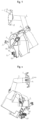
- manipulator 10. main tool changing claw; 11. main clamping claw; 12. main clamping claw driving mechanism; 13. tool holder slot; 2. manipulator mounting arm; 21. mounting arm hinge portion; 22. first mounting arm connecting portion; 23. second mounting arm connecting portion; 24. third mounting arm connecting portion; 25. fourth mounting arm connecting portion; 26. manipulator rotation driving mechanism mounting portion; 27. second driving motor installation cavity; 3. manipulator mounting base; 30. guide rail slider mounting portion; 31. first driving motor mounting portion; 32. manipulator mounting arm installation portion; 4. manipulator rotation driving mechanism; 40. second driving motor; 5. manipulator swinging driving mechanism; 6. manipulator horizontal moving driving mechanism; 60. guide rail slider; 61. rack; 62. gear; 63. first driving motor; 7. travel switch; 80. guide rail; 81. machine tool bed; 82. machine tool spindle; 83. tool magazine; 84. truss; 85. machine tool slide; 9. machine tool changer
- a machine tool changer includes: a manipulator 1; a manipulator mounting arm 2; a manipulator mounting base 3; a manipulator rotation driving mechanism 4; a manipulator swinging driving mechanism 5; and a manipulator horizontal moving driving mechanism 6, wherein the manipulator 1 is mounted on the manipulator mounting arm 2, which is mounted with the manipulator rotation driving mechanism 4 for driving the manipulator 1 to rotate around a horizontal axis, the manipulator mounting arm 2 is mounted on the manipulator mounting base 3, which is mounted with a manipulator swinging driving mechanism 5 for driving the manipulator mounting arm 2 to swing around the horizontal axis, and the manipulator mounting base 3 is mounted with the manipulator horizontal moving driving mechanism 6 for driving the manipulator mounting base 3 to move horizontally to make the manipulator 1 approach or move away from a machine tool spindle.
- the manipulator mounting base 3 includes a guide rail slider mounting portion 30, a first driving motor mounting portion 31, and a manipulator mounting arm installation portion 32.
- the guide rail slider mounting portion 30 is a metal plate structure
- the first driving motor mounting portion 31 is arranged on one side of the guide rail slider mounting portion 30 at a certain angle.
- the guide rail slider mounting portion 30 and the first driving motor mounting portion 31 are arranged perpendicularly.
- An upper portion of one end of the guide rail slider mounting portion 30 extends outward to form the manipulator mounting arm installation portion 32.
- the guide rail slider mounting portion 30, the first driving motor mounting portion 31, and the manipulator mounting arm installation portion 32 are an integrally cast structure.
- the manipulator mounting base 3 is also provided with structures such as reinforcement ribs and weight-reducing holes to improve strength and reduce weight.
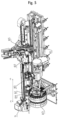
- the manipulator horizontal moving driving mechanism 6 is mounted on the manipulator mounting base 3. As shown in Figs. 1 and 2 , the manipulator horizontal moving driving mechanism 6 includes a guide rail slider 60, a rack 61, a gear 62, and a first driving motor 63.
- the guide rail slider 60 is mounted on the manipulator mounting base 3 and connected to a guide rail 80 which is arranged on a machine tool bed 81, and the first driving motor 63 is mounted on the manipulator mounting base 3 and connected to the gear 62, which meshes with the rack 61 arranged on the machine tool bed 81.
- the first driving motor is a servo motor.
- the guide rail slider 60 is mounted on a bottom surface of the guide rail slider mounting portion 30.
- there is a plurality of guide rail sliders 60 which are connected to the guide rail 80 arranged on the machine tool bed 81.
- the guide rail on which the guide rail sliders 60 are mounted is identical to the guide rail for horizontal movement of the machine tool spindle, that is, the machine tool changer and a machine tool slide (the machine tool spindle is mounted on the guide rail on the machine tool bed through the machine tool slide) share the same horizontal guide rail.
- the first driving motor 63 is mounted on the first driving motor mounting portion 31. The first driving motor 63 is connected to the gear 62 through a reducer.
- the first driving motor 63, the reducer, and the gear 62 are located in a space below the guide rail slider 60.
- the gear 62 meshes with the rack 61 arranged on the machine tool bed 81, and the rack is arranged parallel to the guide rail on the machine tool bed.
- the first driving motor 63 drives the gear 62 to rotate through the reducer, and the gear meshes with the rack, thereby driving the manipulator mounting base to move horizontally back and forth on the guide rail of the machine tool bed.
- An upper portion of one end of the manipulator mounting base is the manipulator mounting arm installation portion 32.
- the manipulator mounting arm 2 is hinged on the manipulator mounting arm installation portion 32, and the manipulator is mounted on the manipulator mounting arm.
- the horizontal movement of the manipulator mounting base can make the manipulator approach or move away from the machine tool spindle.
- the manipulator mounting arm 2 includes a mounting arm hinge portion 21, a first mounting arm link portion 22, a second mounting arm link portion 23, a third mounting arm link portion 24, a fourth mounting arm link portion 25, and a manipulator rotation driving mechanism mounting portion 26.
- the manipulator mounting arm installation portion 32 is mounted with a fixed shaft 33.
- the mounting arm hinge portion 21 is mounted on the fixed shaft 33 through a bearing.
- the mounting arm hinge portion 21 is provided with the first mounting arm link portion 22.
- Another end of the first mounting arm link portion 22 is provided with the second mounting arm link portion 23.
- the first mounting arm link portion 22 and the second mounting arm link portion 23 are arranged at a certain angle, and the axis of the fixed shaft 33 is perpendicular to the plane formed by the first mounting arm link portion 22 and the second mounting arm link portion 23. Another end of the second mounting arm link portion 23 is provided with the third mounting arm link portion 24. The third mounting arm link portion 24 is arranged parallel to the axial direction of the fixed shaft 33. Another end of the third mounting arm link portion 24 is provided with the fourth mounting arm link portion 25. The fourth mounting arm link portion 25 is parallel to the plane formed by the first mounting arm link portion 22 and the second mounting arm link portion 23. Another end of the fourth mounting arm link portion 25 is the manipulator rotation driving mechanism mounting portion 26.
- the manipulator mounting arm 2 can be assembled from a plurality of link structures or integrally machined.
- the mounting arm link portions are shell structures with internal cavities to facilitate the arrangement of various electrical or hydraulic pipelines, etc. Meanwhile, the structure of the manipulator mounting arm eliminates the motion interference between the tool magazine and the machine tool spindle during the operation of the machine tool changer.
- the manipulator mounting arm 2 is mounted on the fixed shaft 33 on the manipulator mounting base 3 through a bearing.
- the manipulator swinging driving mechanism 5 is a linear driving device.
- One end of the linear driving device is hinged to the manipulator mounting arm 2 or the manipulator mounting base 3, and another end is fixedly connected to the manipulator mounting base 3 or the manipulator mounting arm 2.
- the linear driving device is a hydraulic cylinder.
- One end of a piston rod of the hydraulic cylinder is hinged to the manipulator mounting base 3.
- one end of the piston rod of the hydraulic cylinder is hinged to an upper edge of the manipulator mounting arm installation portion.
- One end of the body of the hydraulic cylinder is fixedly connected to the manipulator mounting arm through a hydraulic cylinder fixing frame. The movement of the piston rod of the hydraulic cylinder can drive the manipulator mounting arm to swing around the fixed shaft (axis B-B in Fig. 4 ).
- a free end of the fourth mounting arm link portion 25 is the manipulator rotation driving mechanism mounting portion 26.
- a second driving motor installation cavity 27 is provided in the manipulator rotation driving mechanism mounting portion 26.
- the second driving motor is mounted in the second driving motor installation cavity.
- the second driving motor is connected to the manipulator through a reducer to drive the manipulator to rotate around a central axis (axis A-A in Fig. 3 ).
- the reducer is an RV reducer
- the second driving motor is a servo motor.
- the manipulator 1 includes a main tool changing claw 10, a main clamping claw 11, and a main clamping claw driving mechanism 12, the main tool changing claw 10 has a tool holder slot 13, the main clamping claw driving mechanism 12 is arranged at a bayonet end of the tool holder slot 13 on the main tool changing claw 10, and the main clamping claw 11 is fixed on the main clamping claw driving mechanism 12, which can drive the main clamping claw 11 to move toward the tool holder slot 13 to clamp or release a tool holder in the tool holder slot 13.
- the main tool changing claw is provided with a hydraulic cavity close to the bayonet end of the tool holder slot. The hydraulic cavity is connected to a hydraulic pump station through a pipeline.
- the main clamping claw is a metal plate structure and is arranged in the hydraulic cavity through a travel limit pin.
- a high-pressure fluid from the hydraulic pump station can drive the main clamping claw to move within the hydraulic cavity to clamp or release the tool holder placed in the tool holder slot 13.
- a travel switch 7 is also mounted on the manipulator mounting base 3 to facilitate control and position detection of the machine tool changer. Specifically, by arranging the travel switch, the current position of the manipulator can be obtained in real-time, and the manipulator can be controlled to carry out acceleration and deceleration or uniform speed movement so that the manipulator accurately moves to the current position of the machine tool spindle to implement the tool changing of the machine tool spindle.
- the manipulator which changes tools shares a single guide rail with a machine tool slide 85, and thus, the manipulator which changes tools can move horizontally along the machine tool bed quickly and conveniently to perform tool changes for the machine tool spindle.
- the machine tool changer according to the present invention eliminates the need for the machine tool spindle (machine tool slide) to move horizontally on the machine tool bed to a tool changing area or a machining area during a tool change. Consequently, the machine tool spindle can change tools at any horizontal position within the machining area of the machine tool.
- the machine tool spindle can immediately machine a workpiece without requiring any idle travel of the machine tool spindle (machine tool slide), significantly reducing tool change time and improving machining efficiency. Meanwhile, the machine tool spindle no longer requires the machine tool slide to move back and forth during tool changes, thereby reducing wear on the guide rail and slide, and extending the service life of the machine tool. Additionally, the machine tool changer is relatively lightweight, facilitating control and high-speed operation and further enhancing tool change efficiency.
- the machine tool includes: the machine tool bed 81; a machine tool spindle 82; a tool magazine 83; and the machine tool changer according to the present invention, wherein the machine tool spindle 82 is mounted on the machine tool bed 81, one end of the machine tool bed 81 is provided with the tool magazine 83, the machine tool changer is mounted on the machine tool bed 81, the manipulator horizontal moving driving mechanism 6 can drive the machine tool changer to move horizontally on the machine tool bed 81 to make the manipulator 1 approach or move away from the machine tool spindle 82.
- the machine tool spindle assembly is provided on a guide rail arranged horizontally along the machine tool bed and can move horizontally along the guide rail to machine workpieces.
- One end of the machine tool bed is mounted with the tool magazine.
- the tool magazine is a disc-type tool magazine.
- a truss 84 is arranged between the machine tool bed and the tool magazine.
- An extended guide rail docking with the horizontal guide rail on the machine tool bed is provided on the truss.
- the machine tool changer can move horizontally along the horizontal guide rail on the machine tool bed or the extended guide rail. That is, the guide rail slider of the machine tool changer is mounted on the guide rails.
- the truss 84 is provided to reduce the length of the machine tool bed, thereby saving material for the machine tool bed and reducing manufacturing costs.
- the guide rail 80 connected to the guide rail slider 60 of the manipulator horizontal moving driving mechanism 6 is identical to the guide rail used for horizontal movement of the machine tool spindle 82, further simplifying the structure and facilitating installation and adjustment.
- a machine tool changing method of the machine tool according to the present invention including:
Landscapes
- Engineering & Computer Science (AREA)
- Mechanical Engineering (AREA)
- Automatic Tool Replacement In Machine Tools (AREA)
Applications Claiming Priority (2)
| Application Number | Priority Date | Filing Date | Title |
|---|---|---|---|
| CN202210523704.1A CN114871818B (zh) | 2022-05-13 | 2022-05-13 | 一种机床换刀装置、机床以及机床换刀方法 |
| PCT/CN2022/136823 WO2023216570A1 (zh) | 2022-05-13 | 2022-12-06 | 一种机床换刀装置、机床以及机床换刀方法 |
Publications (2)
| Publication Number | Publication Date |
|---|---|
| EP4523844A1 true EP4523844A1 (de) | 2025-03-19 |
| EP4523844A4 EP4523844A4 (de) | 2025-12-31 |
Family
ID=82675211
Family Applications (1)
| Application Number | Title | Priority Date | Filing Date |
|---|---|---|---|
| EP22941505.4A Pending EP4523844A4 (de) | 2022-05-13 | 2022-12-06 | Werkzeugwechselvorrichtung für werkzeugmaschine, werkzeugmaschine und werkzeugwechselverfahren für werkzeugmaschine |
Country Status (6)
| Country | Link |
|---|---|
| US (1) | US20250332673A1 (de) |
| EP (1) | EP4523844A4 (de) |
| JP (1) | JP7805091B2 (de) |
| KR (1) | KR20240166506A (de) |
| CN (1) | CN114871818B (de) |
| WO (1) | WO2023216570A1 (de) |
Families Citing this family (4)
| Publication number | Priority date | Publication date | Assignee | Title |
|---|---|---|---|---|
| CN114871818B (zh) * | 2022-05-13 | 2024-12-13 | 科德数控股份有限公司 | 一种机床换刀装置、机床以及机床换刀方法 |
| CN120170524B (zh) * | 2025-05-19 | 2025-07-22 | 昆山北钜机械有限公司 | 数控刀库机床生产用换刀钻孔装置 |
| CN120362397B (zh) * | 2025-05-28 | 2025-11-14 | 江苏屹伟不锈钢管业有限公司 | 一种高强耐热镁合金管件锻造装置 |
| CN121054293B (zh) * | 2025-11-04 | 2026-02-03 | 聚变新能(安徽)有限公司 | 装卸工装 |
Family Cites Families (28)
| Publication number | Priority date | Publication date | Assignee | Title |
|---|---|---|---|---|
| JPS63180439A (ja) * | 1987-01-21 | 1988-07-25 | Ikegai Corp | タ−ニングセンタの工具交換装置 |
| JPH0818215B2 (ja) * | 1990-01-18 | 1996-02-28 | 豊和工業株式会社 | 工具交換装置の交換アーム |
| JPH03264235A (ja) * | 1990-03-12 | 1991-11-25 | Matsuura Kikai Seisakusho:Kk | 自動工具交換装置の工具把持アーム |
| JPH09285930A (ja) * | 1996-04-19 | 1997-11-04 | Denso Corp | 工具交換装置 |
| DE19854276C2 (de) * | 1998-11-25 | 2002-09-26 | Hans Joachim Laempe | Werkzeugmaschinen-Anordnung mit einer Vorrichtung für einen automatischen Werkzeugwechsel |
| CN101011801A (zh) * | 2007-02-06 | 2007-08-08 | 南通纵横国际股份有限公司 | 新型机械手换刀机构 |
| WO2009008204A1 (ja) * | 2007-07-10 | 2009-01-15 | Pascal Engineering Corporation | 工具交換装置 |
| CN201109038Y (zh) * | 2007-09-13 | 2008-09-03 | 北京精雕科技有限公司 | 一种摆臂式直排刀库 |
| JP2010194698A (ja) * | 2009-02-27 | 2010-09-09 | Denso Wave Inc | 生産システム |
| DE102009031202A1 (de) * | 2009-06-29 | 2010-12-30 | Grob-Werke Gmbh & Co. Kg | Werkzeugmaschine mit einer Werkzeugwechselvorrichtung |
| CN201799896U (zh) * | 2010-08-31 | 2011-04-20 | 南京航空航天大学 | 一种采用电动推杆的快速换刀机械手 |
| CN101947738A (zh) * | 2010-08-31 | 2011-01-19 | 南京航空航天大学 | 一种采用电动推杆的快速换刀机械手 |
| DE102011006811A1 (de) * | 2011-04-05 | 2012-10-11 | Deckel Maho Pfronten Gmbh | Werkzeug-Handhabungseinrichtung für Werkzeugmaschinen |
| CN102601657B (zh) * | 2011-12-26 | 2014-04-16 | 上海三一精机有限公司 | 一种刀库的换刀机械手结构 |
| CN102554269B (zh) * | 2012-01-19 | 2013-11-20 | 沈阳第一机床厂 | 一种机床车磨中心 |
| JP5964165B2 (ja) * | 2012-07-26 | 2016-08-03 | 株式会社メクトロン | 工作機械の自動工具交換装置 |
| CN103203645A (zh) * | 2013-03-18 | 2013-07-17 | 上海三一精机有限公司 | 一种卧式镗铣加工中心摆臂导轨链式刀库结构 |
| CN103862314A (zh) * | 2014-03-11 | 2014-06-18 | 上海三一精机有限公司 | 一种可扩展的换刀结构及加工中心 |
| JP6423209B2 (ja) * | 2014-09-08 | 2018-11-14 | Dmg森精機株式会社 | 工作機械 |
| EP3208035A4 (de) * | 2014-10-18 | 2018-07-11 | Horkos Corporation | Horizontales maschinenwerkzeug |
| CN209394358U (zh) * | 2018-11-15 | 2019-09-17 | 陕西科技大学 | 一种具备立卧转换功能的换刀装置 |
| CN109176106A (zh) * | 2018-11-15 | 2019-01-11 | 陕西科技大学 | 一种具备立卧转换功能的换刀装置及其换刀方法 |
| CN109605100A (zh) * | 2018-12-21 | 2019-04-12 | 广州鑫利数控科技有限公司 | 一种数控机床自动换刀装置及方法 |
| JP2020192656A (ja) * | 2019-05-30 | 2020-12-03 | 株式会社Aqua・J | ワーク搬送装置 |
| CN110524295A (zh) * | 2019-10-08 | 2019-12-03 | 常州市德速机械有限公司 | 滑轨式链式刀库 |
| CN213672788U (zh) * | 2020-09-25 | 2021-07-13 | 广东创能精密机械有限公司 | 一种车铣复合加工机床 |
| CN217596551U (zh) * | 2022-05-13 | 2022-10-18 | 科德数控股份有限公司 | 一种机床换刀装置和机床 |
| CN114871818B (zh) * | 2022-05-13 | 2024-12-13 | 科德数控股份有限公司 | 一种机床换刀装置、机床以及机床换刀方法 |
-
2022
- 2022-05-13 CN CN202210523704.1A patent/CN114871818B/zh active Active
- 2022-12-06 EP EP22941505.4A patent/EP4523844A4/de active Pending
- 2022-12-06 JP JP2024556562A patent/JP7805091B2/ja active Active
- 2022-12-06 WO PCT/CN2022/136823 patent/WO2023216570A1/zh not_active Ceased
- 2022-12-06 US US18/865,658 patent/US20250332673A1/en active Pending
- 2022-12-06 KR KR1020247032581A patent/KR20240166506A/ko active Pending
Also Published As
| Publication number | Publication date |
|---|---|
| CN114871818A (zh) | 2022-08-09 |
| JP2025511603A (ja) | 2025-04-16 |
| JP7805091B2 (ja) | 2026-01-23 |
| US20250332673A1 (en) | 2025-10-30 |
| WO2023216570A1 (zh) | 2023-11-16 |
| EP4523844A4 (de) | 2025-12-31 |
| CN114871818B (zh) | 2024-12-13 |
| KR20240166506A (ko) | 2024-11-26 |
Similar Documents
| Publication | Publication Date | Title |
|---|---|---|
| EP4523844A1 (de) | Werkzeugwechselvorrichtung für werkzeugmaschine, werkzeugmaschine und werkzeugwechselverfahren für werkzeugmaschine | |
| CN217596551U (zh) | 一种机床换刀装置和机床 | |
| CN221110662U (zh) | 一种阀座零件的加工装置 | |
| RU2844934C2 (ru) | Станок с устройством для смены инструмента | |
| CN218081616U (zh) | 一种数控机床用自动装夹装置 | |
| CN219562672U (zh) | 一种夹取复杂铝件的打磨夹爪装置 | |
| CN118081407A (zh) | 一种智能制造的数控机床夹紧装置 | |
| CN215786530U (zh) | 一种自动化锻造用可调式导轨夹飞边机 | |
| CN113953860B (zh) | 带有智能夹持机构的数控加工中心 | |
| CN213225163U (zh) | 一种滚珠齿面螺栓定位夹具 | |
| CN212634960U (zh) | 一种主轴箱移动的钻攻中心 | |
| CN212419739U (zh) | 智能自动化多驱动机床 | |
| CN211029157U (zh) | 一种自动翻转装置 | |
| CN114683423A (zh) | 一种划片机显微镜结构 | |
| CN108655469B (zh) | 以铣代车专用加工设备 | |
| CN218693746U (zh) | 一种压铸机用自动化取件机构 | |
| CN214816935U (zh) | 一种车床机械手 | |
| CN222470735U (zh) | 一种机床 | |
| CN219274684U (zh) | 一种合金刀头加工用双工位机械手 | |
| CN219310237U (zh) | 切槽夹持固定装置及其切槽机 | |
| CN223673741U (zh) | 一种用于转子绕线上料机的三轴机械手 | |
| CN219254739U (zh) | 一种主轴中轴套整形设备 | |
| CN221985095U (zh) | 一种机器人用机械臂 | |
| CN218612875U (zh) | 一种轴类零件加工定位平台 | |
| CN222958010U (zh) | 一种机床加工用移动结构 |
Legal Events
| Date | Code | Title | Description |
|---|---|---|---|
| STAA | Information on the status of an ep patent application or granted ep patent |
Free format text: STATUS: THE INTERNATIONAL PUBLICATION HAS BEEN MADE |
|
| PUAI | Public reference made under article 153(3) epc to a published international application that has entered the european phase |
Free format text: ORIGINAL CODE: 0009012 |
|
| STAA | Information on the status of an ep patent application or granted ep patent |
Free format text: STATUS: REQUEST FOR EXAMINATION WAS MADE |
|
| 17P | Request for examination filed |
Effective date: 20241213 |
|
| AK | Designated contracting states |
Kind code of ref document: A1 Designated state(s): AL AT BE BG CH CY CZ DE DK EE ES FI FR GB GR HR HU IE IS IT LI LT LU LV MC ME MK MT NL NO PL PT RO RS SE SI SK SM TR |
|
| DAV | Request for validation of the european patent (deleted) | ||
| DAX | Request for extension of the european patent (deleted) | ||
| RIC1 | Information provided on ipc code assigned before grant |
Ipc: B23Q 3/155 20060101AFI20250718BHEP |
|
| A4 | Supplementary search report drawn up and despatched |
Effective date: 20251128 |
|
| RIC1 | Information provided on ipc code assigned before grant |
Ipc: B23Q 3/155 20060101AFI20251124BHEP |